

Page 1
INSTALLATION GUIDE
NI 9925 Outdoor IP54 Enclosure
Wireless/Ethernet Enclosure for NI cDAQ-9181/9191 Chassis
This guide describes how to install and use the National Instruments 9925 outdoor IP54
enclosure with the NI cDAQ-9181/9191 chassis. The NI 9925 provides a minimum ingress
protection (IP) of IP54 against dust and water for outdoor or industrial environments when
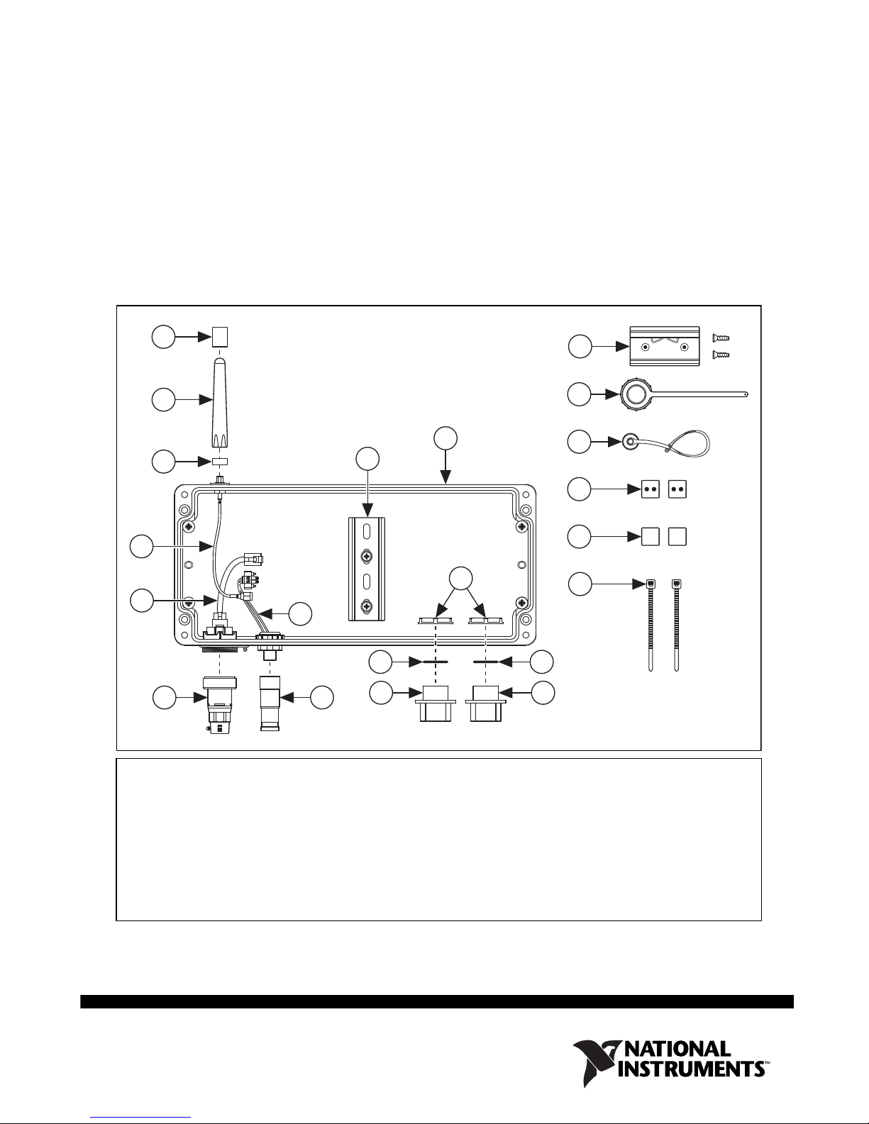
installed according to these instructions with the connectors provided. Figure 1 shows the
components in the NI 9925 kit.
13
12
1
2
5
3
9
1011
4
6
7
8
14
15
16
17
18
19
7
8
1 Antenna IP Sleeve
2 2.4 GHz Antenna
3 Antenna IP Boot
4 DIN Rail
5 NI 9925 Enclosure
6 I/O Cable Clamp Nuts
7 I/O Cable Clamp Gaskets
8 I/O Cable Clamps
9 Internal Power Cable
10 M12 Field Termination Power Connector Kit
Figure 1. NI 9925 Outdoor IP54 Enclosure Kit Components
11 Ethernet Connector Kit
12 Internal RJ45 Ethernet Cable
13 Internal Antenna Cable
14 DIN Rail Mounting Clip and
FLH #6-32 × 5/16” Screws
15 Ethernet End Cap
16 M12 Power End Cap
17 Grommets, Split
18 Grommets, Blank
19 Zip Ties For Cable Management
Page 2

For more information about IP ratings, refer to the Understanding IP Ratings section. For
NI cDAQ-9181/9191 chassis specifications, refer to the NI cDAQ-918x/919x User Manual,
available from
ni.com/manuals.
Figure 2 shows the NI 9925 dimensions.
4x Ø6.5 mm
360.0 mm
(14.17 in.)
61.8 mm
(2.43 in.)
340.0 mm
(13.39 in.)
Mounting Holes
(0.26 in.)
109.0 mm
(4.29 in.)
Mounting
Holes
21.0 mm
(0.83 in.)
Figure 2. NI 9925 Dimensions and Mounting Hole Locations
Setting Up and Installing the NI 9925
81.5 mm
(3.21 in.)
160.0 mm
(6.30 in.)
91.0 mm
(3.58 in.)
You need a number 2 Phillips screwdriver and a 0.125 in. flathead screwdriver to install the
NI 9925. Complete the following steps to set up and install the NI 9925.
1. Remove the NI 9925 from the package and inspect it and the kit contents. Contact NI if the
enclosure appears damaged. Do not install a damaged enclosure or use kit contents that
appear damaged.
2. Use a number 2 Phillips screwdriver to loosen the captive screws and remove the enclosure
cover.
3. (Optional) Mount the NI 9925. Refer to Figure 2 for the NI 9925 mounting hole
dimensions.
4. If you are using an NI cDAQ-9191, remove the antenna from the chassis.
NI 9925 Installation Guide 2 ni.com
Page 3
5. Fasten the DIN rail clip to the cDAQ chassis using two FLH #6-32 × 5/16” screws
(included in the kit) with a number 2 Phillips screwdriver, as shown in Figure 3.
Figure 3. Attaching DIN Rail Clip to NI cDAQ-9181/9191 Chassis
6. Insert your C Series I/O module into the NI cDAQ-9181/9191 chassis.
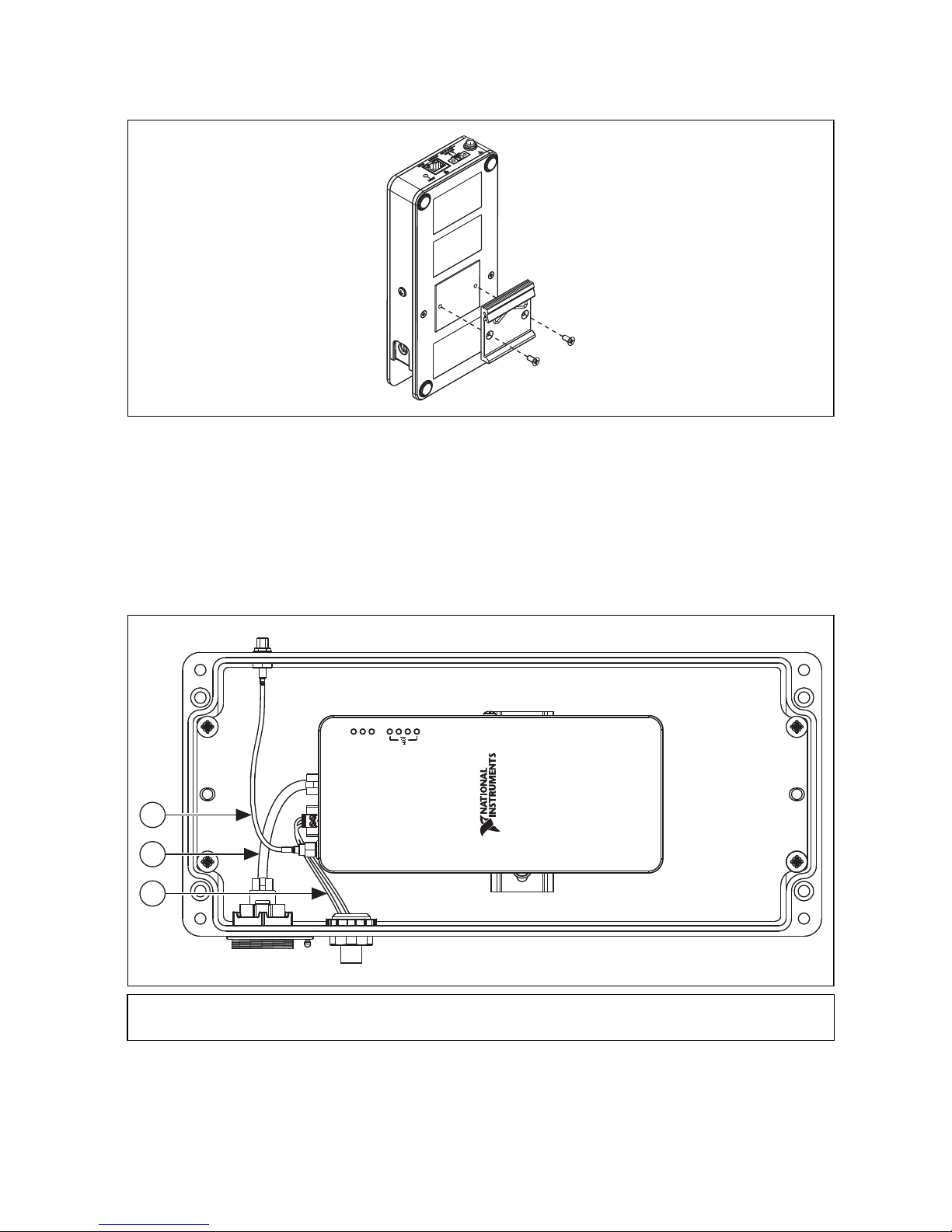
7. Connect the internal power cable from the NI 9925 to the cDAQ chassis as shown in
Figure 4.
8. Connect the internal RJ45 Ethernet cable to the NI 9925 and the cDAQ chassis, as shown
in Figure 4.
ACTIVE
STATU S
POWER
1
2
3
1 Internal Antenna Cable
2 Internal RJ45 Ethernet Cable
© National Instruments Corporation 3 NI 9925 Installation Guide
3 Internal Power Cable
Figure 4. Connecting Internal Cables
Page 4

9. Clip the cDAQ chassis onto the DIN rail in the NI 9925 as shown in Figure 5.
1
2
3
ABC
3
4
2
1
1 DIN Rail Clip 2 DIN Rail Spring 3 DIN Rail
Figure 5. DIN Rail Clip Parts Locator Diagram
10. If you are using an NI cDAQ-9191, connect the internal antenna cable from the NI 9925 to
the cDAQ chassis as shown in Figure 4.
11. On the outside of the enclosure, place the antenna IP boot onto the external antenna
connector with the smaller diameter hole out, as shown in Figure 6A.
1 Antenna IP Boot
2 External Antenna Connector
3 Antenna
4 Antenna IP Sleeve
Figure 6. Antenna Assembly Installation
Note For Ethernet-only use, attaching the antenna on the NI 9925 is optional; it does
not affect IP rating. However, attaching the antenna does offer protection to the
antenna connector on the enclosure.
12. Screw the antenna onto the external antenna connector until it bottoms out as shown in
Figure 6B.
13. Slide the antenna IP sleeve down the antenna and over the antenna IP boot until the antenna
IP sleeve touches the enclosure as shown in Figure 6C.
14. Connect an external IP rated RJ45 Ethernet cable to the external Ethernet connector on the
NI 9925 as shown in Figure 7. Refer to the IP Rated Cables section for information about
ordering and making custom IP rated RJ45 Ethernet cables.
NI 9925 Installation Guide 4 ni.com
Page 5

7
1 External RJ45 Ethernet Cable
2 External M12 Power Cable
3 I/O Cables
4 I/O Cable Clamps and Grommets
6
5
21
4
6
5
4
3 3
5 I/O Cable Clamp Gaskets
6 I/O Cable Clamp Nut
7 Ground Wire
Figure 7. Connecting External Cables/Components
15. Connect an external IP rated M12 power cable to the external M12 power connector on the
NI 9925 as shown in Figure 7. Refer to the IP Rated Cables section for information about
ordering and making custom IP rated M12 power cables.
Note When either the external M12 power connector or external Ethernet connector
on the NI 9925 is not in use, cover that connector with the compatible end cap.
16. Connect the I/O cable(s) from the C Series module and route through one or both of the
I/O openings. Refer to the IP Rated Cables section for information about making and
connecting IP rated I/O cables.
17. Connect a ground wire to the chassis ground screw on the cDAQ chassis as described in the
NI cDAQ-918x/919x User Manual. Route the ground wire through one of the I/O openings,
© National Instruments Corporation 5 NI 9925 Installation Guide
Page 6

as described in the Building IP Rated I/O Cables section. Terminate the ground wire to the
1
2
3
4
+
–
nearest earth ground or grounded structure.
Caution For I/O openings on the NI 9925 that are not in use, use the blank grommets
in the cable clamps to seal the openings and maintain an IP54 rating.
18. Reattach the enclosure cover by tightening the captive screws with a number 2 Phillips
screwdriver.
IP Rated Cables
This section contains information about using the field termination connectors that are shipped
in the NI 9925 outdoor IP enclosure kit to make your own cable lengths. You can order IP rated
cables and accessories from NI.
Building an IP Rated M12 Power Field Termination Cable
One M12 power female field termination connector kit is included in the NI 9925 kit for creating
a custom M12 power cable. To build an M12 field termination cable, complete the following
steps.
Caution Only use the connectors provided with the NI 9925 to build your cables.
Note Be sure to route the wires through the plastic and rubber sealing grommets and
the backshell before connecting to the screw terminals on the M12 field termination
connector.
1. Build the M12 power female field termination connector by connecting the positive lead of
the primary power supply to Pin 4. The pin number is marked on the inside of the field
termination connector, next to the respective terminal, as shown in Figure 8.
Figure 8. M12 Power Female Field Termination Connector Pinout
2. Connect the negative lead to Pin 3, as shown in Figure 8.
Note When the external M12 power connector on the NI 9925 is not in use, cover
the connector with the M12 power end cap.
NI 9925 Installation Guide 6 ni.com
Page 7

Building an IP Rated RJ45 Ethernet Cable
The Ethernet field termination connector kit is included in the NI 9925 kit for creating a custom
IP rated RJ45 Ethernet cable. Refer to the SCPFE Wiring/Assembly Instructions document
included in the field termination connector kit for instructions about how to build an IP rated
Ethernet cable.
Caution Only use the connectors provided with the NI 9925 to build your cables.
Note When the external Ethernet connector on the NI 9925 is not in use, cover the
connector with the Ethernet end cap.
Building IP Rated I/O Cables
The two-piece clamp system, consisting of a cable clamp and a grommet, allows prefabricated
cables to route I/O out of the NI 9925. When the proper grommet is selected, the clamp system
meets a minimum IP rating of IP54. Grommets with two holes route two cables at once. Blank
grommets are also provided, allowing for custom cable configuration. For more information
about IP ratings, refer to the Understanding IP Ratings section.
Caution Only use the connectors provided with the NI 9925 to build your cables.
Note To ensure that the NI cDAQ-9181/9191 chassis meets specified requirements,
use one of the clamps to route ground outside of the NI 9925 outdoor IP enclosure.
Caution For I/O openings on the NI 9925 that are not in use, use the blank grommets
in the cable clamps to seal the openings and maintain an IP54 rating.
To use the clamp system, complete the following steps:
1. Choose the appropriately sized grommet for the cable diameter width. Blank grommets are
provided for use with custom cable sizes and to seal unused I/O openings.
2. Place the grommet around the cable(s) leaving enough length to go through the enclosure
hole and into the C Series I/O module, as shown in Figure 7.
3. Open the cable clamp. You may need to pry it open with a 0.125 in. flathead screwdriver.
4. Press the grommet containing the cable into the open cable clamp.
5. Press the two halves of the cable clamp together until they lock together.
6. Place the gasket over the clamp thread, thread the cable(s) through the enclosure hole, and
insert the clamp into the enclosure hole.
7. Secure the clamp system with the provided nut.
© National Instruments Corporation 7 NI 9925 Installation Guide
Page 8

Ordering NI IP Rated Cables
Table 1 lists the optional cable accessories for use with the NI 9925. Go to ni.com for more
information about these accessories.
Table 1. Optional Cable Accessories
NI Part Number Description
196648-05 IP rated, 5 meter M12 power cable, pigtail
196650-05 IP rated, 5 meter Ethernet cable
196647-01 Cable clamp replacements: two solid grommets and four assorted two-hole split
grommets
Understanding IP Ratings
Proper use and installation of an NI cDAQ-9181/9191 chassis in an NI 9925 outdoor IP54
enclosure provides a minimum IP rating of IP54 from outdoor and industrial environments. An
IP rating of IP54 protects against entry by dust particles and splashing water from all directions.
The two-digit ingress protection (IP) rating is defined by the IEC 60529 standard and specifies
the degree to which the enclosures protects against entry of dust (represented by the first digit)
and splashing water (represented by the second digit), as shown in Table 2.
Table 2. IP Ratings
1st
No.
0 No protection 0 No protection
1 Protects against objects greater than
2 Protects against objects greater than
3 Protects against objects greater than
4 Protects against objects greater than
5 Dust-protected (no harmful deposit) 5 Protects against low pressure water jets
6 Dust-tight 6 Protects against high pressure water jets
Protection Against Solid Objects
50 mm
12.5 mm
2.5 mm
1mm
2nd
No.
1 Protects against vertically dripping water
2 Protects against direct sprays up to
15° from vertical
3 Protects against direct sprays up to
60° from vertical
4 Protects against direct sprays from all
angles
7 Immersible in water up to 1 m
8 Immersible in water beyond 1 m
Protection Against Water
NI 9925 Installation Guide 8 ni.com
Page 9

Environmental Management
⬉ᄤֵᙃѻક∵ᶧࠊㅵ⧚ࡲ⊩ ˄Ё
RoHS
˅
Ёᅶ᠋
National Instruments
ヺড়Ё⬉ᄤֵᙃѻકЁ䰤ࠊՓ⫼ᶤѯ᳝ᆇ⠽䋼ᣛҸ
(RoHS)
DŽ݇Ѣ
National Instruments
Ё
RoHS
ড়㾘ᗻֵᙃˈ䇋ⱏᔩ
ni.com/
environment/rohs_china
DŽ
(For information about China RoHS compliance,
go to
ni.com/environment/rohs_china
.)
NI is committed to designing and manufacturing products in an environmentally responsible
manner. NI recognizes that eliminating certain hazardous substances from our products is
beneficial to the environment and to NI customers.
For additional environmental information, refer to the NI and the Environment Web page at
ni.com/environment. This page contains the environmental regulations and directives with
which NI complies, as well as other environmental information not included in this document.
Waste Electrical and Electronic Equipment (WEEE)
EU Customers At the end of the product life cycle, all products must be sent to
a WEEE recycling center. For more information about WEEE recycling centers,
National Instruments WEEE initiatives, and compliance with WEEE Directive
2002/96/EC on Waste and Electronic Equipment, visit
.
weee
ni.com/environment/
© National Instruments Corporation 9 NI 9925 Installation Guide
Page 10

LabVIEW, National Instruments, NI, ni.com, the National Instruments corporate logo, and the Eagle logo are trademarks of National Instruments
Corporation. Refer to the Trademark Information at ni.com/trademarks for other National Instruments trademarks. Other product and
company names mentioned herein are trademarks or trade names of their respective companies. For patents covering National Instruments
products/technology, refer to the appropriate location: Help»Patents in your software, the patents.txt file on your media, or the National
Instruments Patents Notice at ni.com/patents. Refer to the Export Compliance Information at ni.com/legal/export-compliance
for the National Instruments global trade compliance policy and how to obtain relevant HTS codes, ECCNs, and other import/export data.
© 2011 National Instruments Corporation. All rights reserved.
372467A-01 Jul11
 Loading...