

Page 1
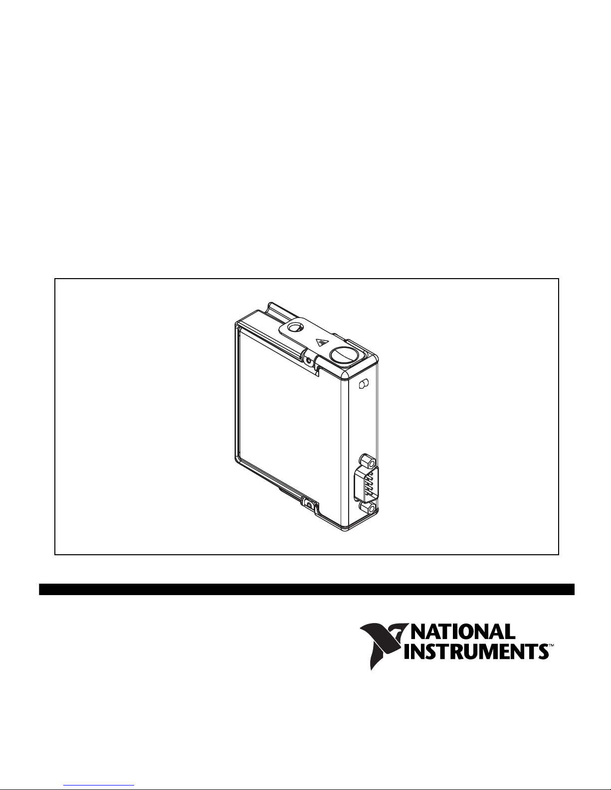
OPERATING INSTRUCTIONS
NI 9882
1-Port DeviceNet Module
Page 2

These operating instructions describe how to use the National
Instruments (NI) 9882 module. For information about installing,
configuring, and programming your system, refer to your system
documentation. The NI 9882 module requires the latest
NI-DeviceNet software to be installed. The latest version of the
NI-DeviceNet software is available at
Note The safety guidelines and specifications in this
ni.com/downloads.
document are specific to the NI 9882. The other
components in your system may not meet the same safety
ratings and specifications. Refer to the documentation for
each component in your system to determine the safety
ratings and specifications for the entire system.
Safety Guidelines
Operate the NI 9882 only as described in these operating
instructions.
Hot Surface This icon denotes that the component may be
hot. Touching this component may result in bodily injury.
NI 9882 Operating Instructions 2 ni.com
Page 3
Safety Guidelines for Hazardous Locations
The NI 9882 is suitable for use in Class I, Division 2, Groups A, B,
C, D, T4 hazardous locations; Class I, Zone 2, AEx nA II T4 and
Ex nA II T4 hazardous locations; and nonhazardous locations only.
Follow these guidelines if you are installing the NI 9882 in a
potentially explosive environment. Not following these guidelines
may result in serious injury or death.
Caution Do not disconnect I/O-side wires or connectors
unless power has been switched off or the area is known
to be nonhazardous.
Caution Do not remove modules unless power has been
switched off or the area is known to be nonhazardous.
Caution Substitution of components may impair
suitability for Class I, Division 2.
Caution For Zone 2 applications, install the
CompactRIO system in an enclosure rated to at least
IP 54 as defined by IEC 60529 and EN 60529.
© National Instruments Corp. 3 NI 9882 Operating Instructions
Page 4
Caution For Zone 2 applications, install a protection
device between the CAN signals and the NI 9882 CAN
pins. The device must prevent the CAN Port-to-COM
voltage from exceeding 55 V if there is a transient
overvoltage condition.
Special Conditions for Safe Use in Europe
This equipment has been evaluated as Ex nA II T4 equipment
under DEMKO Certificate No. 07 ATEX 0626664X. Each module
is marked II 3G and is suitable for use in Zone 2 hazardous
locations.
Wiring the NI 9882
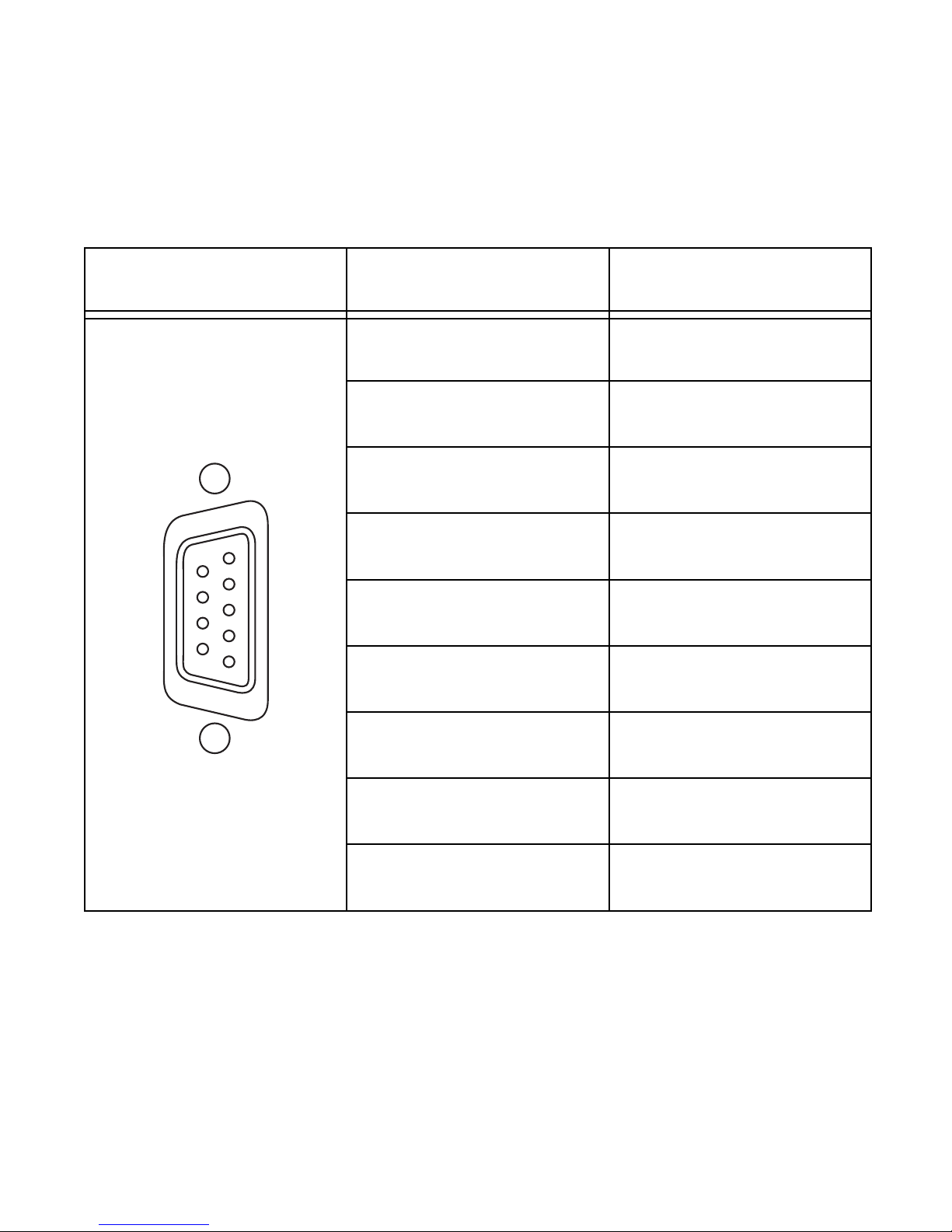
The NI 9882 has one 9-pin male D-Sub connector that provides
connections to a CAN bus. The NI 9882 has pins for CAN_H and
CAN_L, to which you connect the CAN bus signals. Connect these
signals using twisted-pair cable.
The port has two common pins (COM) that are internally
connected to the module’s isolated reference and serve as the
reference ground for CAN_H and CAN_L. You can connect the
CAN bus reference ground (sometimes referred to as CAN_V–) to
NI 9882 Operating Instructions 4 ni.com
Page 5
one or both COM pins. The port also has an optional shield pin,
SHLD, that you can connect to a shielded CAN cable. Connecting
SHLD may improve signal integrity and EMC performance in a
noisy environment.
Caution You must use a UL listed ITE power supply
marked LPS with the NI 9882.
The NI 9882 requires an external power supply in the range of
+9 to +30 V to operate. Supply power to the NI 9882 V
Note Power on V
is required for DeviceNET
SUP
SUP
pin.
operation.
The NI 9882 pinout is listed in Table 1.
The NI 9882 features software-selectable bus termination for
High-Speed CAN transceivers. On the NI 9882, you can enable
120
termination resistors between CAN_H and CAN_L through
an API call. Table 3 lists recommended termination resistor values.
© National Instruments Corp. 5 NI 9882 Operating Instructions
Page 6
6
7
8
9
1
2
3
4
5
Table 1. Pin Assignments for the NI 9882
Connector Pin Signal
1 No Connection (NC)
2 CAN_L
3 COM
4 NC
5 SHLD
6 COM
7 CAN_H
8 NC
9 V
NI 9882 Operating Instructions 6 ni.com
SUP
Page 7

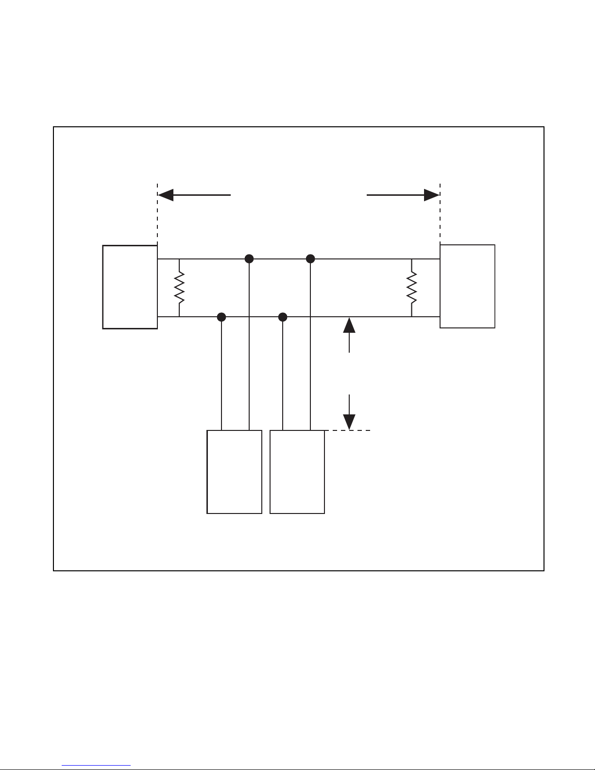
CAN Bus Topology and Termination
A CAN bus consists of two or more CAN nodes cabled together.
The CAN_H and CAN_L pins of each node are connected to the
main CAN bus cable through a short connection known as a “stub.”
The pair of signal wires, CAN_H and CAN_L, constitutes a
transmission line. If the transmission line is not terminated,
each signal change on the bus causes reflections that may cause
communication errors. Because the CAN bus is bidirectional, both
ends of the cable must be terminated. However, this requirement
does not mean that every node on the bus should have a termination
resistor; only the two nodes at the far end of the cable should have
termination resistors.
Figure 1 shows a simplified diagram of a CAN bus with multiple
CAN nodes and proper termination resistor (R
© National Instruments Corp. 7 NI 9882 Operating Instructions
) locations.
t
Page 8
CAN
Node
CAN
Node
CAN
Node
R
t
R
t
CAN
Node
CAN_H
CAN_L
CAN_H
CAN_L
CAN_H
CAN_L
CAN_H
CAN_L
Bus Cable Length
Stub
Length
NI 9882 Operating Instructions 8 ni.com
Figure 1. CAN Bus Topology and Termination Resistor Locations
Page 9

Connecting a CAN Bus to the NI 9882
CAN0
NI 9882
CAN Device
R
t
CAN
Cable
(With
Optional
Shield)
(SHLD)
CAN_H
CAN_L
V
sup
COM
R
t
(SHLD)
CAN_H
CAN_L
V
sup
COM
You can connect the NI 9882 port to any location on a CAN bus.
Figure 2 shows one example of connecting the NI 9882 directly to
one CAN node.
Figure 2. Connecting the NI 9882 to a CAN Device
Cabling Requirements for the NI 9882
This section deals with cabling specifications, termination
resistors, cable lengths, and the number of CAN nodes that can
exist in a system.
© National Instruments Corp. 9 NI 9882 Operating Instructions
Page 10
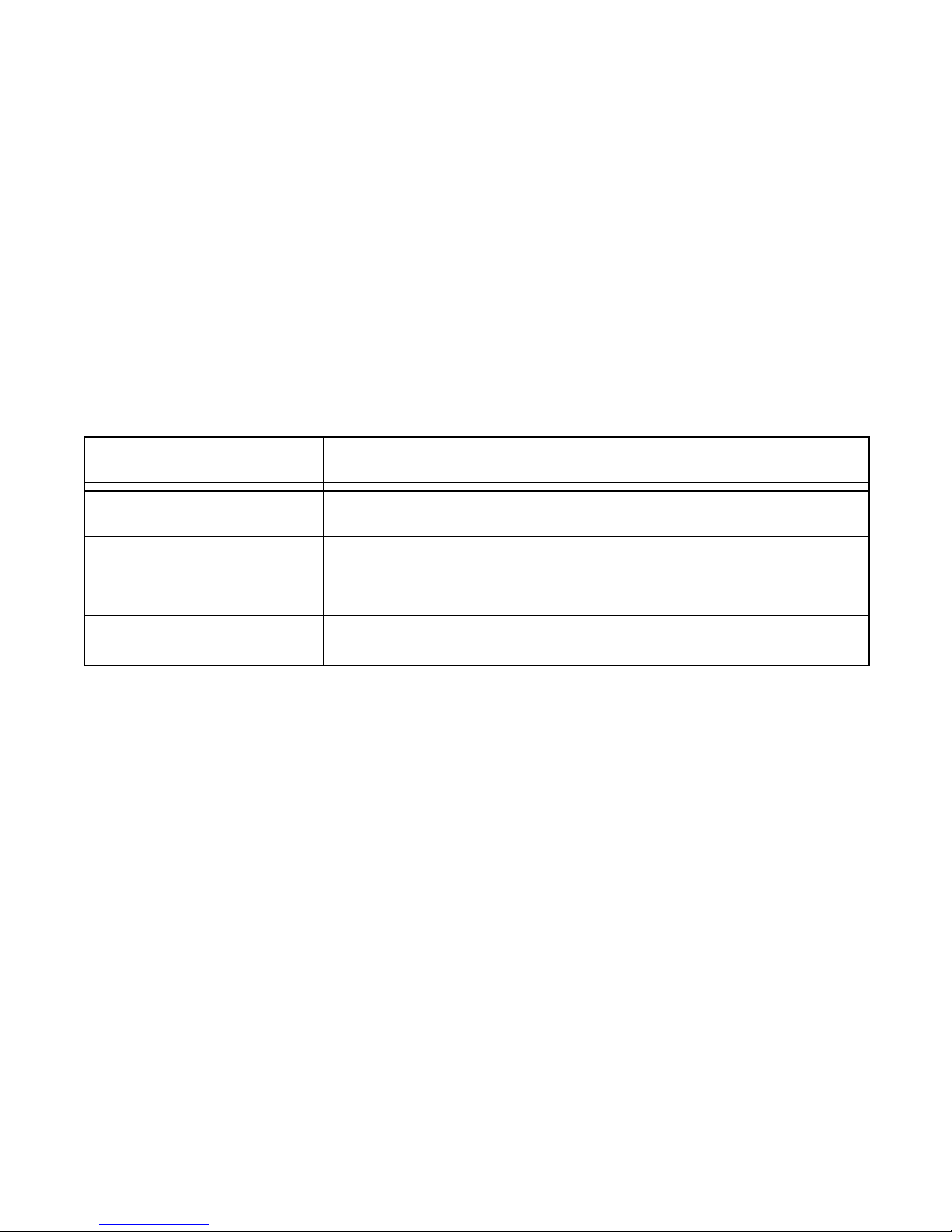
Cable Specifications
Cables should meet the physical medium requirements specified
in ISO 11898, shown in Table 2. Belden cable (3084A) meets all
these requirements and should be suitable for most applications.
Table 2. ISO 11898 Specifications for Characteristics of a CAN_H and
CAN_L Pair of Wires
Characteristic Valu e
Impedance 95 minimum, 120 nominal, 140 maximum
Length-related
resistance
Specific line delay 5 ns/m nominal
70 m/m nominal
Termination Resistors
The termination resistors (Rt) should match the nominal
impedance of the CAN cable and therefore comply with the values
in Table 3. The onboard, software-selectable termination has a
nominal value of 120
termination, use the values listed in Table 3.
. If you are not using the onboard
NI 9882 Operating Instructions 10 ni.com
Page 11
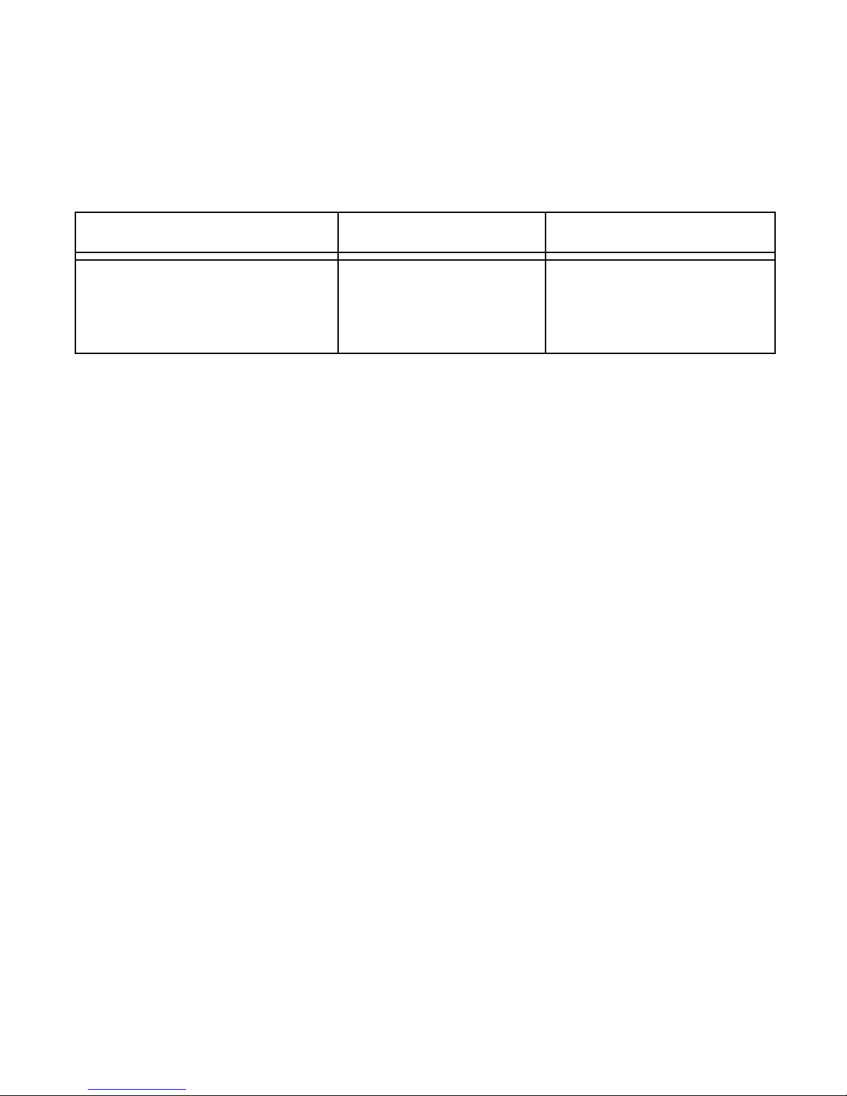
Table 3. Termination Resistor Specification
Characteristic Va lu e Condition
Termination resistor, R
t
100 min,
120 nominal,
130 max
Minimum power
dissipation: 220 mW
Cable Lengths
The cabling characteristics and desired bit transmission rates affect
the allowable cable length. You can find detailed cable length
recommendations in the ISO 11898, CiA DS 102, and DeviceNet
specifications.
ISO 11898 specifies 40 m total cable length with a maximum
stub length of 0.3 m for a bit rate of 1 Mb/s. The ISO 11898
specification says that significantly longer cable lengths may be
allowed at lower bit rates, but you should analyze each node for
signal integrity problems.
© National Instruments Corp. 11 NI 9882 Operating Instructions
Page 12

Number of CAN Nodes
The maximum number of nodes depends on the electrical
characteristics of the nodes on the network. If all nodes meet the
ISO 11898 requirements, you can connect at least 30 nodes to
the bus. You can connect higher numbers of nodes if the nodes’
electrical characteristics do not degrade signal quality below
ISO 11898 signal level specifications.
The NI 9882 electrical characteristics allow at least 110 CAN ports
on a network.
NI 9882 Hardware Overview
The NI 9882 has one full-featured DeviceNet port that is isolated
from the other modules in the system. The port has a Bosch DCAN
CAN controller that is CAN 2.0B-compatible and fully
supports both 11-bit and 29-bit identifiers. The port also has a
NXP PCA82C251T High-Speed CAN transceiver that is fully
compatible with the ISO 11898 standard and supports baud rates
up to 1 Mbps.
NI 9882 Operating Instructions 12 ni.com
Page 13

V
sup
COM
Ext Pwr
+
Supply
_
Required
DeviceNet
Controller
Rx
Tx
Rx
Tx
DeviceNet
Transceiver
CAN_H
CAN_L
Figure 3. NI 9882 Hardware Overview
Sleep Mode (CompactRIO Only)
You can enable sleep mode for the CompactRIO system in
software. In sleep mode, the system consumes less power and may
dissipate less heat. When a system is in sleep mode, you cannot
communicate with the modules. Refer to the Specifications section
for more information about power consumption and thermal
dissipation.
© National Instruments Corp. 13 NI 9882 Operating Instructions
Page 14

Specifications
The following specifications are typical for the range – 40 to 70 °C
unless otherwise noted.
High-Speed CAN Characteristics
Transceiver........................................NXP PCA82C251T
Max baud rate ...................................1 Mbps
CAN_H, CAN_L bus lines
voltage...............................................–27 to +40 VDC
Supply voltage range (V
SUP
)
CAN ........................................... +9 to +30 VDC
MTBF ...............................................Contact NI for Bellcore
MTBF or MIL-HDBK-217F
specifications.
Power Requirements
Power consumption from chassis
Active mode ...............................1 W max
Sleep mode .................................2.55 mW max
NI 9882 Operating Instructions 14 ni.com
Page 15

Thermal dissipation (at 70 °C)
Active mode ...............................1.25 W max
Sleep mode .................................250 mW max
Physical Characteristics
To clean the module, wipe it with a dry towel.
Weight...............................................Approx. 144 g (5.0 oz)
Safety
Maximum Voltage
1
Connect only voltages that are within these limits.
Port-to-COM.....................................–27 to +40 VDC max,
Measurement Category I
Measurement Category I is for measurements performed on
circuits not directly connected to the electrical distribution system
referred to as MAINS voltage. MAINS is a hazardous live electrical
supply system that powers equipment. This category is for
measurements of voltages from specially protected secondary
1
The maximum voltage that can be applied or output between any port or V
terminal and a COM terminal without creating a safety hazard.
SUP
© National Instruments Corp. 15 NI 9882 Operating Instructions
Page 16

circuits. Such voltage measurements include signal levels, special
equipment, limited-energy parts of equipment, circuits powered by
regulated low-voltage sources, and electronics.
Caution Do not connect to signals or use for
measurements within Measurement Categories II, III,
or IV.
Isolation Voltages
Port-to-earth ground
Withstand.................................... 1000 V
, verified by a 5 s
rms
dielectric withstand test
Continuous ................................. 60 VDC,
Measurement Category I
Safety Standards
This product meets the requirements of the following standards
of safety for electrical equipment for measurement, control, and
laboratory use:
• IEC 61010-1, EN 61010-1
• UL 61010-1, CSA 61010-1
NI 9882 Operating Instructions 16 ni.com
Page 17

Note For UL and other safety certifications, refer to the
product label or the Online Product Certification section.
Hazardous Locations
U.S. (UL) .......................................... Class I, Division 2,
Groups A, B, C, D, T4;
Class I, Zone 2,
AEx nA II T4
Canada (C-UL) .................................Class I, Division 2,
Groups A, B, C, D, T4;
Class I, Zone 2,
Ex nA II T4
Europe (DEMKO).............................Ex nA II T4
Environmental
Refer to the installation instructions for the chassis you are using
for more information about meeting these specifications.
Operating temperature ......................– 40 to 70 °C
Storage temperature.......................... – 40 to 85 °C
Ingress protection.............................. IP 40
© National Instruments Corp. 17 NI 9882 Operating Instructions
Page 18

Operating humidity...........................10 to 90% RH,
noncondensing
Storage humidity...............................5 to 95% RH,
noncondensing
Pollution Degree (IEC 60664)..........2
Maximum altitude............................. 2,000 m
Indoor use only.
Shock and Vibration
To meet these specifications, you must panel mount the
CompactRIO system.
Operating vibration,
random (IEC 60068-2-64) ................5 g
, 10 to 500 Hz
rms
Operating shock
(IEC 60068-2-27)..............................30 g, 11 ms half sine,
50 g, 3 ms half sine,
18 shocks at 6 orientations
Operating vibration,
sinusoidal (IEC 60068-2-6) .............. 5 g, 10 to 500 Hz
NI 9882 Operating Instructions 18 ni.com
Page 19

Electromagnetic Compatibility
This product meets the requirements of the following EMC
standards for electrical equipment for measurement, control, and
laboratory use:
• EN 61326 (IEC 61326): Class A emissions; Basic immunity
• EN 55011 (CISPR 11): Group 1, Class A emissions
• AS/NZS CISPR 11: Group 1, Class A emissions
• FCC 47 CFR Part 15B: Class A emissions
• ICES-001: Class A emissions
Note For the standards applied to assess the EMC of this
product, refer to the Online Product Certification section.
Note For EMC compliance, operate this product
according to the documentation.
© National Instruments Corp. 19 NI 9882 Operating Instructions
Page 20

CE Compliance
This product meets the essential requirements of applicable
European Directives as follows:
• 2006/95/EC; Low-Voltage Directive (safety)
• 2004/108/EC; Electromagnetic Compatibility Directive
(EMC)
Online Product Certification
Refer to the product Declaration of Conformity (DoC) for
additional regulatory compliance information. To obtain product
certifications and the DoC for this product, visit
certification
, search by model number or product line, and
ni.com/
click the appropriate link in the Certification column.
Environmental Management
NI is committed to designing and manufacturing products in
an environmentally responsible manner. NI recognizes that
eliminating certain hazardous substances from our products is
beneficial to the environment and to NI customers.
NI 9882 Operating Instructions 20 ni.com
Page 21

For additional environmental information, refer to the NI and the
RoHS
˅
Ёᅶ᠋
National Instruments
ヺড়Ё⬉ᄤֵᙃ
ѻકЁ䰤ࠊՓ⫼ᶤѯ᳝ᆇ⠽䋼ᣛҸ
(RoHS)
DŽ݇Ѣ
National Instruments
Ё
RoHS
ড়㾘ᗻֵᙃˈ䇋ⱏᔩ
ni.com/environment/rohs_china
DŽ
(For information
about China RoHS compliance, go to
ni.com/
environment/rohs_china
.)
Environment Web page at
ni.com/environment. This page
contains the environmental regulations and directives with which
NI complies, as well as other environmental information not
included in this document.
Waste Electrical and Electronic Equipment (WEEE)
EU Customers At the end of the product life cycle, all
products must be sent to a WEEE recycling center.
For more information about WEEE recycling centers,
National Instruments WEEE initiatives, and
compliance with WEEE Directive 2002/96/EC on
Waste and Electronic Equipment, visit
environment/weee
.
ni.com/
© National Instruments Corp. 21 NI 9882 Operating Instructions
Page 22

Where to Go for Support
The National Instruments Web site is your complete resource
for technical support. At
ni.com/support you have access to
everything from troubleshooting and application development
self-help resources to email and phone assistance from
NI Application Engineers.
National Instruments corporate headquarters is located at
11500 North Mopac Expressway, Austin, Texas, 78759-3504.
National Instruments also has offices located around the world
to help address your support needs. For telephone support in the
United States, create your service request at
ni.com/support
and follow the calling instructions or dial 512 795 8248. For
telephone support outside the United States, contact your local
branch office:
Australia 1800 300 800, Austria 43 662 457990-0,
Belgium 32 (0) 2 757 0020, Brazil 55 11 3262 3599,
Canada 800 433 3488, China 86 21 5050 9800,
Czech Republic 420 224 235 774, Denmark 45 45 76 26 00,
Finland 358 (0) 9 725 72511, France 01 57 66 24 24,
Germany 49 89 7413130, India 91 80 41190000,
Israel 972 3 6393737, Italy 39 02 41309277, Japan 0120-527196,
NI 9882 Operating Instructions 22 ni.com
Page 23

Korea 82 02 3451 3400, Lebanon 961 (0) 1 33 28 28,
Malaysia 1800 887710, Mexico 01 800 010 0793,
Netherlands 31 (0) 348 433 466, New Zealand 0800 553 322,
Norway 47 (0) 66 90 76 60, Poland 48 22 328 90 10,
Portugal 351 210 311 210, Russia 7 495 783 6851,
Singapore 1800 226 5886, Slovenia 386 3 425 42 00,
South Africa 27 0 11 805 8197, Spain 34 91 640 0085,
Sweden 46 (0) 8 587 895 00, Switzerland 41 56 2005151,
Taiwan 886 02 2377 2222, Thailand 662 278 6777,
Turkey 90 212 279 3031, United Kingdom 44 (0) 1635 523545
© National Instruments Corp. 23 NI 9882 Operating Instructions
Page 24

LabVIEW, National Instruments, NI, ni.com, the National Instruments corporate logo, and the Eagle logo are
trademarks of National Instruments Corporation. Refer to the Trademark Information at
for other National Instruments trademarks. Other product and company names mentioned herein are trademarks or
trade names of their respective companies. For patents covering National Instruments products/technology, refer to
the appropriate location: Help»Patents in your software, the
Instruments Patent Notice at
© 2010 National Instruments Corp. All rights reserved.
ni.com/patents.
373253A-01 Nov10
ni.com/trademarks
patents.txt file on your media, or the National
 Loading...