


Motion Control
NI 951x User Manual
NI 951x User Manual
July 2009
372153B-01

Support
Worldwide Technical Support and Product Information
ni.com
National Instruments Corporate Headquarters
11500 North Mopac Expressway Austin, Texas 78759-3504 USA Tel: 512 683 0100
Worldwide Offices
Australia 1800 300 800, Austria 43 662 457990-0, Belgium 32 (0) 2 757 0020, Brazil 55 11 3262 3599,
Canada 800 433 3488, China 86 21 5050 9800, Czech Republic 420 224 235 774, Denmark 45 45 76 26 00,
Finland 358 (0) 9 725 72511, France 01 57 66 24 24, Germany 49 89 7413130, India 91 80 41190000,
Israel 972 3 6393737, Italy 39 02 41309277, Japan 0120-527196, Korea 82 02 3451 3400,
Lebanon 961 (0) 1 33 28 28, Malaysia 1800 887710, Mexico 01 800 010 0793, Netherlands 31 (0) 348 433 466,
New Zealand 0800 553 322, Norway 47 (0) 66 90 76 60, Poland 48 22 328 90 10, Portugal 351 210 311 210,
Russia 7 495 783 6851, Singapore 1800 226 5886, Slovenia 386 3 425 42 00, South Africa 27 0 11 805 8197,
Spain 34 91 640 0085, Sweden 46 (0) 8 587 895 00, Switzerland 41 56 2005151, Taiwan 886 02 2377 2222,
Thailand 662 278 6777, Turkey 90 212 279 3031, United Kingdom 44 (0) 1635 523545
For further support information, refer to the Technical Support and Professional Services appendix. To comment
on National Instruments documentation, refer to the National Instruments Web site at
the info code
feedback.
ni.com/info and enter
© 2009 National Instruments Corporation. All rights reserved.

Important Information
Warranty
The NI 9512, NI 9514, and NI 9516 C Series modules are warranted against defects in materials and workmanship for a period of one year
from the date of shipment, as evidenced by receipts or other documentation. National Instruments will, at its option, repair or replace equipment
that proves to be defective during the warranty period. This warranty includes parts and labor.
The media on which you receive National Instruments software are warranted not to fail to execute programming instructions, due to defects in
materials and workmanship, for a period of 90 days from date of shipment, as evidenced by receipts or other documentation. National Instruments
will, at its option, repair or replace software media that do not execute programming instructions if National Instruments receives notice of such defects
during the warranty period. National Instruments does not warrant that the operation of the software shall be uninterrupted or error free.
A Return Material Authorization (RMA) number must be obtained from the factory and clearly marked on the outside of the package before any
equipment will be accepted for warranty work. National Instruments will pay the shipping costs of returning to the owner parts which are covered by
warranty.
National Instruments believes that the information in this document is accurate. The document has been carefully reviewed for technical accuracy. In
the event that technical or typographical errors exist, National Instruments reserves the right to make changes to subsequent editions of this document
without prior notice to holders of this edition. The reader should consult National Instruments if errors are suspected. In no event shall National
Instruments be liable for any damages arising out of or related to this document or the information contained in it.
XCEPT AS SPECIFIED HEREIN, NATIONAL INSTRUMENTS MAKES NO WARRANTIES, EXPRESS OR IMPLIED, AND SPECIFICALLY DISCLAIMS ANY WARRANTY OF
E
MERCHANTABILITY OR FITNESS FOR A PARTICULAR PURPOSE. CUSTOMER’S RIGHT TO RECOVER DAMAGES CAUSED BY FAULT OR NEGLIGENCE ON THE PART OF NATIONAL
NSTRUMENTS SHALL BE LIMITED TO THE AMOUNT THERETOFORE PAID BY THE CUSTOMER. NATIONAL INSTRUMENTS WILL NOT BE LIABLE FOR DAMAGES RESULTING
I
FROM LOSS OF DATA, PROFITS, USE OF PRODUCTS, OR INCIDENTAL OR CONSEQUENTIAL DAMAGES, EVEN IF ADVISED OF THE POSSIBILITY THEREOF. This limitation of
the liability of National Instruments will apply regardless of the form of action, whether in contract or tort, including negligence. Any action against
National Instruments must be brought within one year after the cause of action accrues. National Instruments shall not be liable for any delay in
performance due to causes beyond its reasonable control. The warranty provided herein does not cover damages, defects, malfunctions, or service
failures caused by owner’s failure to follow the National Instruments installation, operation, or maintenance instructions; owner’s modification of the
product; owner’s abuse, misuse, or negligent acts; and power failure or surges, fire, flood, accident, actions of third parties, or other events outside
reasonable control.
Copyright
Under the copyright laws, this publication may not be reproduced or transmitted in any form, electronic or mechanical, including photocopying,
recording, storing in an information retrieval system, or translating, in whole or in part, without the prior written consent of National
Instruments Corporation.
National Instruments respects the intellectual property of others, and we ask our users to do the same. NI software is protected by copyright and other
intellectual property laws. Where NI software may be used to reproduce software or other materials belonging to others, you may use NI software only
to reproduce materials that you may reproduce in accordance with the terms of any applicable license or other legal restriction.
Trademarks
National Instruments, NI, ni.com, and LabVIEW are trademarks of National Instruments Corporation. Refer to the Terms of Use section
ni.com/legal for more information about National Instruments trademarks.
on
Product and company names mentioned herein are trademarks or trade names of their respective companies.
Members of the National Instruments Alliance Partner Program are business entities independent from National Instruments and have no agency,
partnership, or joint-venture relationship with National Instruments.
Patents
For patents covering National Instruments products/technology, refer to the appropriate location: Help»Patents in your software,
the patents.txt file on your media, or the National Instruments Patent Notice at ni.com/patents.
WARNING REGARDING USE OF NATIONAL INSTRUMENTS PRODUCTS
(1) NATIONAL INSTRUMENTS PRODUCTS ARE NOT DESIGNED WITH COMPONENTS AND TESTING FOR A LEVEL OF
RELIABILITY SUITABLE FOR USE IN OR IN CONNECTION WITH SURGICAL IMPLANTS OR AS CRITICAL COMPONENTS IN
ANY LIFE SUPPORT SYSTEMS WHOSE FAILURE TO PERFORM CAN REASONABLY BE EXPECTED TO CAUSE SIGNIFICANT
INJURY TO A HUMAN.
(2) IN ANY APPLICATION, INCLUDING THE ABOVE, RELIABILITY OF OPERATION OF THE SOFTWARE PRODUCTS CAN BE
IMPAIRED BY ADVERSE FACTORS, INCLUDING BUT NOT LIMITED TO FLUCTUATIONS IN ELECTRICAL POWER SUPPLY,
COMPUTER HARDWARE MALFUNCTIONS, COMPUTER OPERATING SYSTEM SOFTWARE FITNESS, FITNESS OF COMPILERS
AND DEVELOPMENT SOFTWARE USED TO DEVELOP AN APPLICATION, INSTALLATION ERRORS, SOFTWARE AND HARDWARE
COMPATIBILITY PROBLEMS, MALFUNCTIONS OR FAILURES OF ELECTRONIC MONITORING OR CONTROL DEVICES,
TRANSIENT FAILURES OF ELECTRONIC SYSTEMS (HARDWARE AND/OR SOFTWARE), UNANTICIPATED USES OR MISUSES, OR
ERRORS ON THE PART OF THE USER OR APPLICATIONS DESIGNER (ADVERSE FACTORS SUCH AS THESE ARE HEREAFTER
COLLECTIVELY TERMED “SYSTEM FAILURES”). ANY APPLICATION WHERE A SYSTEM FAILURE WOULD CREATE A RISK OF
HARM TO PROPERTY OR PERSONS (INCLUDING THE RISK OF BODILY INJURY AND DEATH) SHOULD NOT BE RELIANT SOLELY
UPON ONE FORM OF ELECTRONIC SYSTEM DUE TO THE RISK OF SYSTEM FAILURE. TO AVOID DAMAGE, INJURY, OR DEATH,
THE USER OR APPLICATION DESIGNER MUST TAKE REASONABLY PRUDENT STEPS TO PROTECT AGAINST SYSTEM FAILURES,
INCLUDING BUT NOT LIMITED TO BACK-UP OR SHUT DOWN MECHANISMS. BECAUSE EACH END-USER SYSTEM IS
CUSTOMIZED AND DIFFERS FROM NATIONAL INSTRUMENTS' TESTING PLATFORMS AND BECAUSE A USER OR APPLICATION
DESIGNER MAY USE NATIONAL INSTRUMENTS PRODUCTS IN COMBINATION WITH OTHER PRODUCTS IN A MANNER NOT
EVALUATED OR CONTEMPLATED BY NATIONAL INSTRUMENTS, THE USER OR APPLICATION DESIGNER IS ULTIMATELY
RESPONSIBLE FOR VERIFYING AND VALIDATING THE SUITABILITY OF NATIONAL INSTRUMENTS PRODUCTS WHENEVER
NATIONAL INSTRUMENTS PRODUCTS ARE INCORPORATED IN A SYSTEM OR APPLICATION, INCLUDING, WITHOUT
LIMITATION, THE APPROPRIATE DESIGN, PROCESS AND SAFETY LEVEL OF SUCH SYSTEM OR APPLICATION.

Compliance
Electromagnetic Compatibility Information
This hardware has been tested and found to comply with the applicable regulatory requirements and limits for electromagnetic
compatibility (EMC) as indicated in the hardware’s Declaration of Conformity (DoC)
designed to provide reasonable protection against harmful interference when the hardware is operated in the intended
electromagnetic environment. In special cases, for example when either highly sensitive or noisy hardware is being used in close
proximity, additional mitigation measures may have to be employed to minimize the potential for electromagnetic interference.
While this hardware is compliant with the applicable regulatory EMC requirements, there is no guarantee that interference will
not occur in a particular installation. To minimize the potential for the hardware to cause interference to radio and television
reception or to experience unacceptable performance degradation, install and use this hardware in strict accordance with the
instructions in the hardware documentation and the DoC
If this hardware does cause interference with licensed radio communications services or other nearby electronics, which can be
determined by turning the hardware off and on, you are encouraged to try to correct the interference by one or more of the
following measures:
• Reorient the antenna of the receiver (the device suffering interference).
• Relocate the transmitter (the device generating interference) with respect to the receiver.
• Plug the transmitter into a different outlet so that the transmitter and the receiver are on different branch circuits.
Some hardware may require the use of a metal, shielded enclosure (windowless version) to meet the EMC requirements for
special EMC environments such as, for marine use or in heavy industrial areas. Refer to the hardware’s user documentation and
the DoC
When the hardware is connected to a test object or to test leads, the system may become more sensitive to disturbances or may
cause interference in the local electromagnetic environment.
Operation of this hardware in a residential area is likely to cause harmful interference. Users are required to correct the
interference at their own expense or cease operation of the hardware.
Changes or modifications not expressly approved by National Instruments could void the user’s right to operate the hardware
under the local regulatory rules.
1
for product installation requirements.
1
.
1
. These requirements and limits are
1
The Declaration of Conformity (DoC) contains important EMC compliance information and instructions for the user or
installer. To obtain the DoC for this product, visit
and click the appropriate link in the Certification column.
ni.com/certification, search by model number or product line,

Contents
About This Manual
Conventions ...................................................................................................................ix
Related Documentation..................................................................................................x
Chapter 1
Introduction and Installation
About the NI 951x Drive Interface Modules .................................................................1-1
Features............................................................................................................1-1
Hardware .........................................................................................................1-1
What You Need to Get Started ......................................................................................1-2
Using the NI 951x Modules in Scan Interface Mode ...................................... 1-2
Using the NI 951x Modules in LabVIEW FPGA Interface Mode..................1-3
Safety Information .........................................................................................................1-3
Special Conditions for Marine Applications ...................................................1-3
Optional Equipment.......................................................................................................1-4
Chapter 2
Hardware Overview
NI 951x Connections .....................................................................................................2-2
NI 9512 Connections.......................................................................................2-2
NI 9514 Connections.......................................................................................2-4
NI 9516 Connections.......................................................................................2-6
User Connectors.............................................................................................................2-8
NI 9512 Connectors.........................................................................................2-9
NI 9514 Connectors.........................................................................................2-11
NI 9516 Connectors.........................................................................................2-13
LED Indicators...............................................................................................................2-15
Axis Status.......................................................................................................2-15
Encoder Active ................................................................................................2-15
Limit Active.....................................................................................................2-16
Axis Fault ........................................................................................................2-16
© National Instruments Corporation v NI 951x User Manual

Contents
Chapter 3
Signal Connections
Power Connections........................................................................................................ 3-4
Command Signals.......................................................................................................... 3-4
Stepper Command Signals .............................................................................. 3-4
Servo Command Signals................................................................................. 3-7
Additional Drive Signals................................................................................. 3-7
Motion I/O Signals ........................................................................................................ 3-9
Limit and Home Inputs ................................................................................... 3-9
Encoder Inputs ................................................................................................ 3-11
Position Capture Input and Position Compare Output .................................... 3-14
Digital I/O Signals......................................................................................................... 3-15
Digital Inputs................................................................................................... 3-15
Digital Outputs................................................................................................ 3-17
Step (CW)± and Direction (CCW)±................................................. 3-4
Drive Command Output ................................................................... 3-7
Drive Command COM ..................................................................... 3-7
Drive Enable .................................................................................... 3-7
Limit and Home Input Circuit .......................................................... 3-9
Encoder Phase A/Phase B................................................................. 3-12
Encoder Index................................................................................... 3-12
Encoder Input Circuit ....................................................................... 3-13
Chapter 4
Accessory and Cable Connections
Connection to P7000 Series Stepper Drives.................................................................. 4-1
NI 951x Connection Accessories .................................................................................. 4-5
37-Pin Terminal Block Pin Assignments........................................................ 4-5
Signal Connection Recommendations........................................................................... 4-7
General Connection Recommendations.......................................................... 4-7
Limit and Digital Input Connection Recommendations ................................. 4-8
Encoder Connection Recommendations ......................................................... 4-8
Connecting Optional Signals......................................................................................... 4-9
Connecting a Brake Signal.............................................................................. 4-9
NI 951x User Manual vi ni.com

Appendix A
Specifications
Appendix B
Position Command Connections
Appendix C
Technical Support and Professional Services
Glossary
Index
Contents
© National Instruments Corporation vii NI 951x User Manual

About This Manual
This manual describes the electrical and mechanical aspects of the National
Instruments 951x C Series drive interface modules and contains
information concerning installation and operation.
Conventions
This manual uses the following conventions:
<> Angle brackets that contain numbers separated by an ellipsis represent a
range of values associated with a bit or signal name—for example,
AO <3..0>.
» The » symbol leads you through nested menu items and dialog box options
to a final action. The sequence File»Page Setup»Options directs you to
pull down the File menu, select the Page Setup item, and select Options
from the last dialog box.
This icon denotes a tip, which alerts you to advisory information.
This icon denotes a note, which alerts you to important information.
This icon denotes a caution, which advises you of precautions to take to
avoid injury, data loss, or a system crash. When this symbol is marked on a
product, refer to the Safety Information section for information about
precautions to take.
This icon denotes that the component may be hot. Touching this component may
result in bodily injury.
bold Bold text denotes items that you must select or click in the software, such
as menu items and dialog box options. Bold text also denotes parameter
names.
italic Italic text denotes variables, emphasis, a cross-reference, or an introduction
to a key concept. Italic text also denotes text that is a placeholder for a word
or value that you must supply.
monospace Text in this font denotes text or characters that you should enter from the
keyboard, sections of code, programming examples, and syntax examples.
This font is also used for the proper names of disk drives, paths, directories,
programs, subprograms, subroutines, device names, functions, operations,
variables, filenames, and extensions.
© National Instruments Corporation ix NI 951x User Manual

About This Manual
Related Documentation
The following documents contain information you might find helpful as
you read this manual:
• Operating Instructions for the controller and modules (shipped with
the hardware and available from
• NI-Motion Help—Contains information about motion programming
concepts and the NI-Motion architecture. Access the NI-Motion Help
by going to Start»All Programs»NI-Motion»Documentation.
• LabVIEW NI SoftMotion Module Help—Use this help file to learn
about using NI SoftMotion in LabVIEW including information about
function blocks and using NI SoftMotion with the LabVIEW Project.
To access this help file from LabVIEW, select Help»Search the
LabVIEW Help, then expand the LabVIEW NI SoftMotion Module
book on the Contents tab.
• LabVIEW Help—Contains LabVIEW, LabVIEW Real-Time Module,
and LabVIEW FPGA Module programming concepts, instructions,
and reference information. Access the LabVIEW Help by selecting
Help»Search the LabVIEW Help from within LabVIEW.
ni.com/manuals)
NI 951x User Manual x ni.com

Introduction and Installation
This chapter includes information about the features of the National
Instruments 9512, 9514, and 9516 drive interface modules.
Note The remainder of this document will refer to these modules collectively as NI 951x
modules.
About the NI 951x Drive Interface Modules
The NI 951x drive interface modules are a family of C Series motion
modules. These modules enable advanced motion with configuration and
programming using NI LabVIEW.
Features
1
Note Refer to Appendix B, Position Command Connections, for information about using
the NI 9512 module with position command servo drives.
Hardware
The NI 951x modules provide servo or stepper drive interface signals for a
single axis, a full set of motion I/O including inputs for a home switch and limit
switches, incremental encoder inputs for position feedback, and 0 to 30 V
digital input and digital output lines. Refer to Chapter 3, Signal Connections,
for more information about the signals available on each module.
• The NI 9512 is a single-axis stepper or position command drive
interface module with incremental encoder feedback.
• The NI 9514 is a single-axis servo drive interface module with
incremental encoder feedback.
• The NI 9516 is a single-axis servo drive interface module with dual
incremental encoder feedback.
The NI 951x drive interface modules include a processor to run the spline
interpolation engine and patented NI step generation algorithm or
PID control loop/PIVff control loop. Working together they produce
smoother motion resulting in precise motion control.
© National Instruments Corporation 1-1 NI 951x User Manual

Chapter 1 Introduction and Installation
What You Need to Get Started
Using the NI 951x Modules in Scan Interface Mode
Scan Interface mode enables you to use C Series modules directly from the
LabVIEW Real-Time Module. Refer to the CompactRIO Reference and
Procedures (Scan Interface) section of the LabVIEW Help for more
information about using C Series modules in Scan Interface mode.
To set up and use the NI 951x drive interface modules in Scan Interface
mode, you must have the following items:
❑ The following software packages and documentation:
– NI SoftMotion. This software package contains the following
NI software products:
• NI SoftMotion software
• NI-Motion driver software
– LabVIEW Development System
– LabVIEW Real-Time Module
– NI-RIO driver software
Tip Refer to the software documentation for installation instructions.
❑ The following hardware and documentation:
– NI 9512, NI 9514, or NI 9516 drive interface module
– External power supply
Note Refer to the Power Requirements section of Appendix A, Specifications, for power
supply requirements.
– CompactRIO controller and chassis that support the RIO Scan
Interface
or
NI 951x User Manual 1-2 ni.com
– NI 9144 distributed chassis

Chapter 1 Introduction and Installation
Using the NI 951x Modules in LabVIEW FPGA Interface Mode
LabVIEW FPGA Interface mode enables you to use C Series modules from
LabVIEW FPGA VIs. Refer to the CompactRIO Reference and Procedures
(FPGA Interface) section of the LabVIEW Help for more information about
using C Series modules in LabVIEW FPGA Interface mode.
To set up and use the NI 951x drive interface modules in LabVIEW FPGA
Interface mode, you must have the following items:
❑ The following software packages and documentation:
– (optional) NI SoftMotion. This software package contains the
following NI software products:
• NI SoftMotion software
• NI-Motion driver software
– LabVIEW Development System
– LabVIEW Real-Time Module
– LabVIEW FPGA Module
–NI-RIO driver software
Tip Refer to the software documentation for installation instructions.
❑ The following hardware and documentation:
– NI 9512, NI 9514, or NI 9516 drive interface module
– External power supply
Note Refer to the Power Requirements section of Appendix A, Specifications, for power
supply requirements.
– CompactRIO controller and chassis
Safety Information
Special Conditions for Marine Applications
Some modules are Lloyd’s Register (LR) Type Approved for marine
applications. To verify Lloyd’s Register certification, visit
certification
Register mark on the module.
© National Instruments Corporation 1-3 NI 951x User Manual
ni.com/
and search for the LR certificate, or look for the Lloyd’s
Chapter 1 Introduction and Installation
Caution To meet radio frequency emission requirements for marine applications, use
shielded cables and install the system in a metal enclosure. Suppression ferrites must be
installed on power supply inputs near power entries to modules and controllers. Power
supply and module cables must be separated on opposite sides of the enclosure and must
enter and exit through opposing enclosure walls.
Optional Equipment
National Instruments offers several options for connecting NI 951x drive
interface modules to external stepper drives or servo amplifiers including
the following:
• NI 9512-to-P7000 Stepper Drives Connectivity Bundle—Connects
the NI 9512 to the P70530 or P70360 stepper drives available from NI.
(NI part number 780552-01)
• NI 951x Cable and Terminal Block Bundle—Connects the NI 951x
module with the 37-pin spring terminal blocks. (NI part number
780553-01)
• DSUB and MDR Solder Cup Connectors—Simplifies custom cable
creation.
NI part number for DSUB connector: 780549-01
NI part number for MDR connector: 780551-01
• DSUB to Pigtails Cable and MDR to Pigtails Cable—Simplifies
custom cable creation.
NI part number for DSUB cable: 193412-04
NI part number for MDR cable: 193413-04
Caution Do not use the recommended module power supplies to power a drive. Check
your drive documentation for drive power supply requirements.
• +24 V DC power supply
Note Refer to the National Instruments Web site at ni.com for available power supplies.
Refer to Chapter 4, Accessory and Cable Connections, for cable and
terminal block pin assignments. For additional information about these and
other available products refer to the National Instruments Web site at
ni.com, or call your National Instruments sales representative.
NI 951x User Manual 1-4 ni.com
Hardware Overview
This chapter presents an overview of the National Instruments 951x drive
interface module hardware, including connections and connector pin
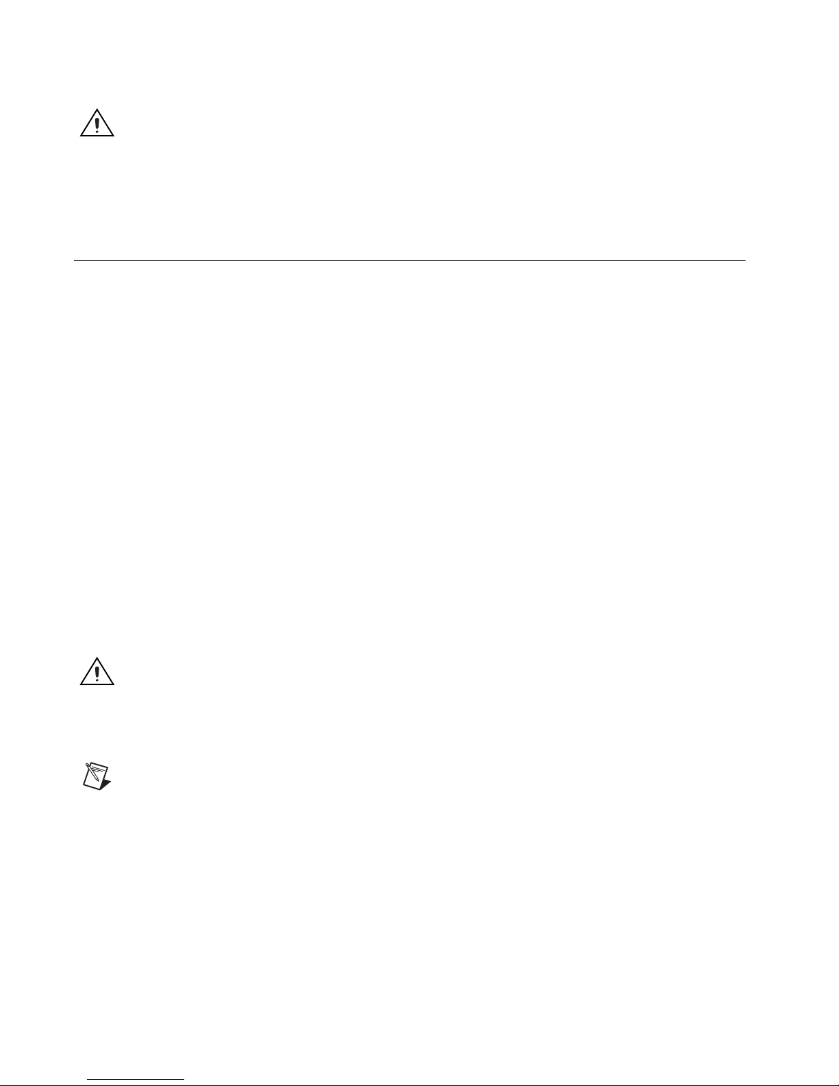
assignments. The following figure shows the NI 951x module.
2
© National Instruments Corporation 2-1 NI 951x User Manual
Figure 2-1. NI 951x Module

Chapter 2 Hardware Overview
NI 951x Connections
This section contains connection information for each drive interface
module, including connection diagrams for a complete system setup.
NI 9512 Connections
Complete the following steps to connect the NI 9512 stepper drive interface
module to drives and other I/O:
1. Install the module in the chassis as specified in the chassis
documentation.
Note Refer to the NI SoftMotion Module book of the LabVIEW Help for information about
chassis, slot, or software restrictions.
2. Connect the module to a drive and other I/O using the
NI 9512-to-P7000 Stepper Drives Connectivity Bundle, the NI 951x
Cable and Terminal Block Bundle, or a custom cable for direct
connectivity.
3. Connect the NI 9512 module to an external power supply.
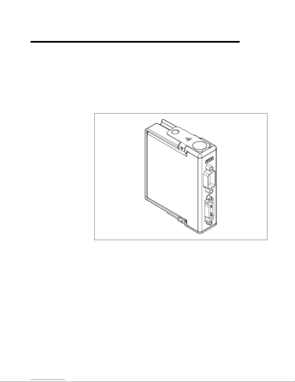
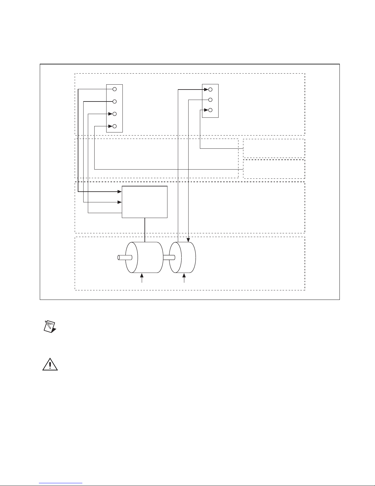
Figure 2-2 shows a simplified connection diagram.
Note Refer to Appendix B, Position Command Connections, for position command signal
information and information about connecting the NI 9512 module to drives that support
position command mode.
Caution Do not connect anything to pins marked Reserved.
NI 951x User Manual 2-2 ni.com
Chapter 2 Hardware Overview
DSUB Connector
Step±/CW
Direction±/CCW
Drive Fault
Drive Enable
NI Connection
Accessory/
Custom Cable
Step±/CW
Direction±/CCW
Drive Fault
Drive Enable
MDR Connector
Encoder 0 Phase A, B, Index
+5 V OUT
Forward, Reverse Limit, Home
V
sup
NI 9512
Limit and Home
Sensors
Power Supply
Drive
Encoder (optional)Stepper Motor
Figure 2-2. NI 9512 Connection Diagram
Note
supply to the V
The NI 9512 requires an external power supply. You can connect the external power
input provided on the DSUB or MDR connector. Do not connect more
sup
than one external power supply to the module.
Motor
© National Instruments Corporation 2-3 NI 951x User Manual
Chapter 2 Hardware Overview
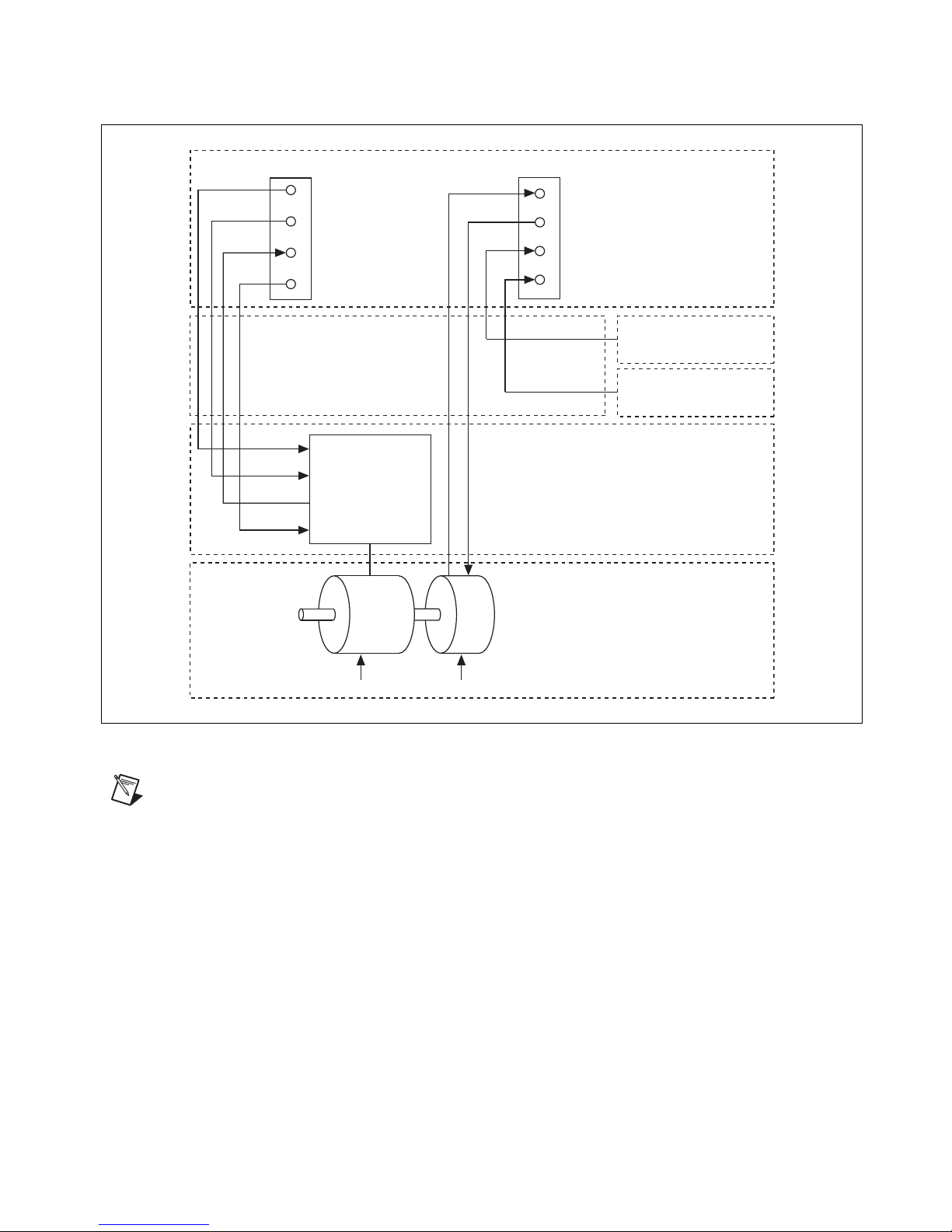
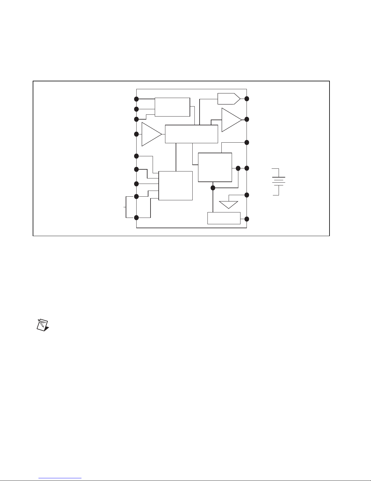
Phase A± (0)
Phase B± (0)
Index± (0)
Position
Capture
Home
Figure 2-3 shows the NI 9512 block diagram. Refer to Chapter 3, Signal
Connections, for more information about the individual signals and
connecting devices to the module.
Receiver
Circuitry
Buffer
Buffer
Buffer
Buffer
Microprocessor
Step ±
Direction ±
Position
Compare
Drive
Enable
Forward
Reverse
Digital
Input
(0-3)
NI 9514 Connections
Complete the following steps to connect the NI 9514 drive interface
module to drives and other I/O:
1. Install the module in the chassis as specified in the chassis
Note Refer to the NI SoftMotion Module book of the LabVIEW Help for information about
chassis, slot, or software restrictions.
Input
Circuitry
+5V Reg
documentation.
Output
Circuitry
V
sup
COM
+5 V OUT
Figure 2-3. NI 9512 Block Diagram
Digital
Output
(0-1)
2. Connect the module to a 37-pin terminal block using the NI 951x to
3. Connect the NI 9514 module to an external power supply.
NI 951x User Manual 2-4 ni.com
37-pin cable, or use a custom cable for direct connectivity.
Chapter 2 Hardware Overview
Figure 2-4 shows a simplified connection diagram.
DSUB Connector
Drive Command
Drive Enable
Drive Fault
V
sup
NI Connection
Accessory/
Custom Cable
Drive Command
Drive Enable
Drive Fault
MDR Connector
Encoder 0 Phase A, B, Index
+5 V OUT
Forward, Reverse Limit, Home
NI 9514
Limit and Home
Sensors
Power Supply
Drive
Motor
EncoderServo Motor
Figure 2-4. NI 9514 Connection Diagram
Note
supply to the V
The NI 9514 requires an external power supply. You can connect the external power
input provided on the DSUB or MDR connector. Do not connect more
sup
than one external power supply to the module.
Caution Do not connect anything to pins marked Reserved.
© National Instruments Corporation 2-5 NI 951x User Manual
Chapter 2 Hardware Overview
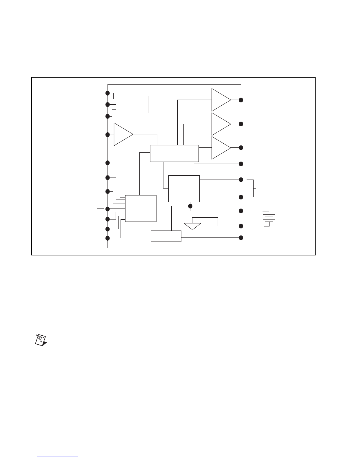
Phase A± (0)
DAC
Phase B± (0)
Index± (0)
Home
Position
Capture
Position
Compare
Receiver
Circuitry
Microprocessor
(PID Loop)
+5V Reg
+5 V OUT
V
sup
COM
Output
Circuitry
Input
Circuitry
Drive
Command
Drive
Enable
Forward
Reverse
Buffer
Buffer
Digital Input (0-1)
Figure 2-5 shows the NI 9514 block diagram. Refer to Chapter 3, Signal
Connections, for more information about the individual signals and
connecting devices to the module.
NI 9516 Connections
Note Refer to the NI SoftMotion Module book of the LabVIEW Help for information about
chassis, slot, or software restrictions.
Figure 2-5. NI 9514 Block Diagram
Complete the following steps to connect the NI 9516 drive interface
module to drives and other I/O:
1. Install the module in the chassis as specified in the chassis
documentation.
2. Connect the module to a 37-pin terminal block using the NI 951x to
37-pin cable, or use a custom cable for direct connectivity.
NI 951x User Manual 2-6 ni.com
Chapter 2 Hardware Overview
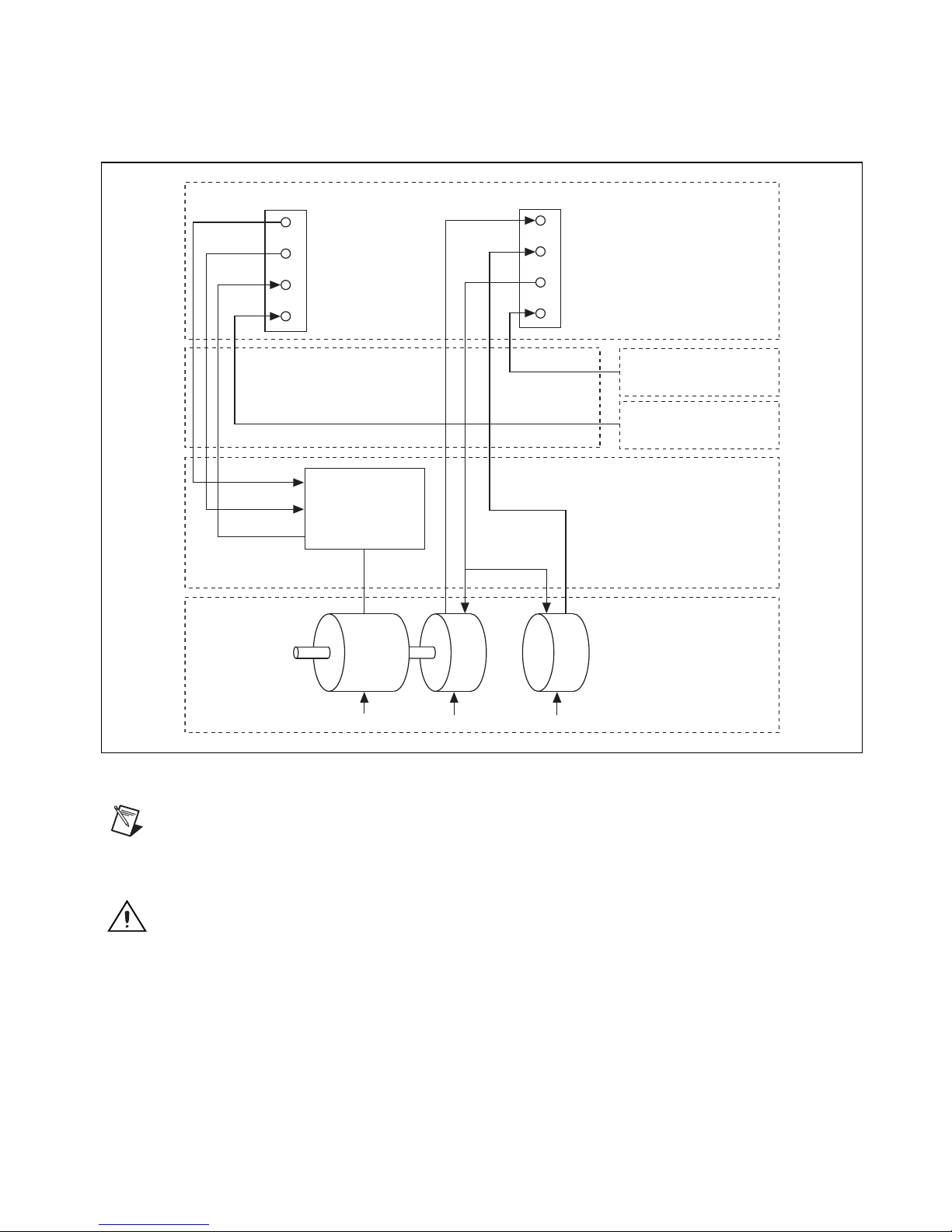
Encoder 0Servo Motor
Drive Command
Drive Enable
Drive Fault
Drive Command
Drive Enable
Drive Fault
V
sup
DSUB Connector
Forward, Reverse Limit, Home
MDR Connector
NI 9516
Drive
Motor
Encoder 0 Phase A, B, Index
Limit and Home
Sensors
Power Supply
Encoder 1 Phase A, B
NI Connection
Accessory/
Custom Cable
Encoder 1
+5 V OUT
Figure 2-6 shows a simplified connection diagram.
Note
The NI 9516 requires an external power supply. You can connect the external power
supply to the V
input provided on the DSUB or MDR connector. Do not connect more
sup
than one external power supply to the module.
Caution Do not connect anything to pins marked Reserved.
Figure 2-6. NI 9516 Connection Diagram
© National Instruments Corporation 2-7 NI 951x User Manual
Chapter 2 Hardware Overview
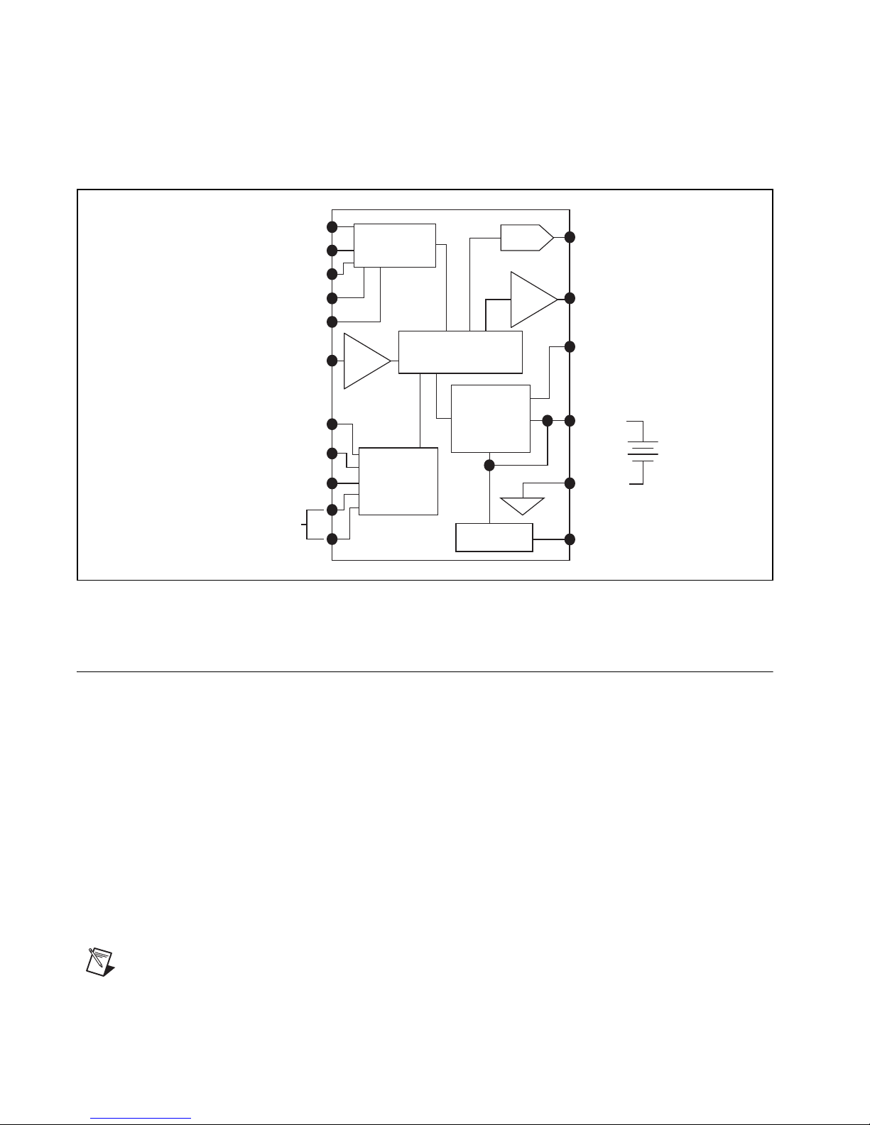
Figure 2-7 shows the NI 9516 block diagram. Refer to Chapter 3, Signal
Connections, for more information about the individual signals and
connecting devices to the module.
Phase A± (0)
Phase B± (0)
Index± (0)
Phase A± (1)
Phase B± (1)
Position
Capture
Home
Forward
Reverse
Digital Input (0-1)
Receiver
Buffer
DAC
Circuitry
Buffer
Microprocessor
(PID Loop)
Output
Circuitry
Input
Circuitry
+5V Reg
Figure 2-7. NI 9516 Block Diagram
Drive
Command
Position
Compare
Drive
Enable
V
sup
COM
+5 V OUT
User Connectors
The NI 951x has two connectors, a 15-pin DSUB drive interface connector
and a 20-pin MDR feedback connector. The 15-pin DSUB includes
command signals for interfacing with stepper drives or servo amplifiers,
0 to 30 V general-purpose digital input and digital output lines, and an input
for power connection.
The 20-pin MDR connector includes incremental encoder feedback inputs,
a +5 V output for encoder power, home, limit, and position compare inputs,
an output for position compare, an additional input for power connection,
and an additional 0 to 30 V general-purpose digital input line. Refer to
Chapter 3, Signal Connections, for details about the signals in each
connector.
Note The remainder of this document does not distinguish between drives and amplifiers.
All references to drives also apply to amplifiers.
NI 951x User Manual 2-8 ni.com
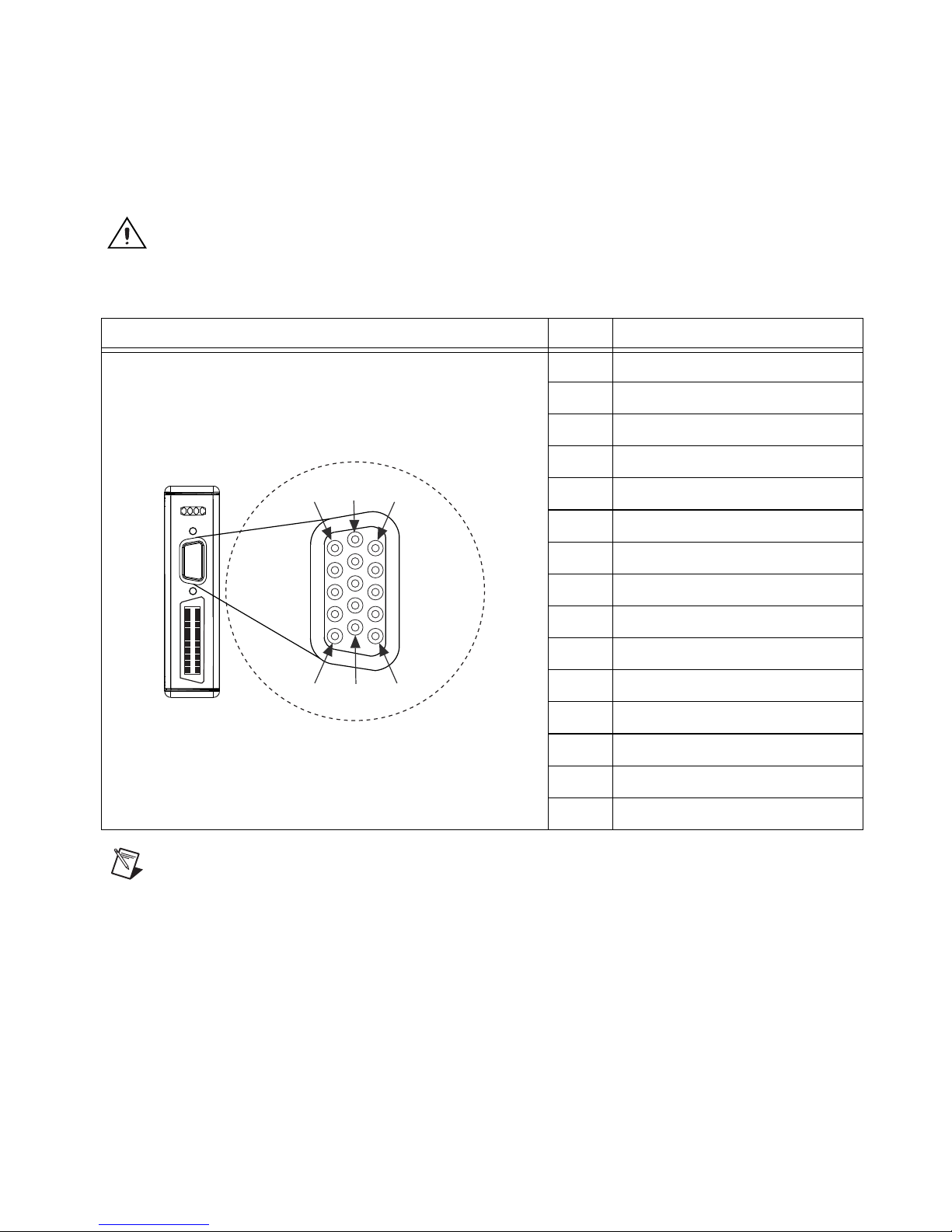
NI 9512 Connectors
Caution Do not connect anything to pins marked Reserved.
Table 2-1. NI 9512 DSUB Control Connector Pin Assignments
Connector Pin Signal
15
Chapter 2 Hardware Overview
Refer to Chapter 4, Accessory and Cable Connections, for cabling options
and connection accessory pin assignments.
1 Reserved
2 Drive Enable
3 Digital Input 3
4 Digital Input 2
10
5
5 Digital Output 1
6 Reserved
7 COM
8 Digital Input 1
9 Direction (CCW)–
10 Step (CW)–
11 Digital Output 0
11
6
1
12 V
sup
13 Direction (CCW)+
14 COM
15 Step (CW)+
Note Refer to Appendix B, Position Command Connections, for position command signal
information and information about connecting the NI 9512 module to position command
drives.
© National Instruments Corporation 2-9 NI 951x User Manual
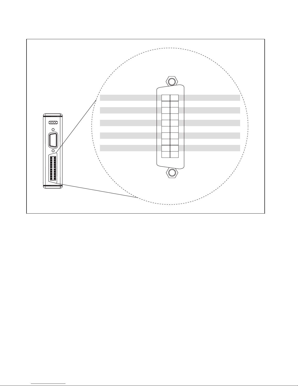
Chapter 2 Hardware Overview
Reverse Limit
Reserved
V
sup
Reserved
COM
Encoder 0 Phase A+
Encoder 0 Phase A–
Encoder 0 Phase B+
Position Capture
Encoder 0 Phase B–
11
12
13
14
15
16
17
18
19
20
1
2
3
4
5
6
7
8
9
10
Forward Limit
Home
COM
Digital Input 0
COM
Encoder 0 Index+
Encoder 0 Index–
COM
+5 V OUT
Position Compare
Figure 2-8. NI 9512 MDR Connector Pin Assignments
NI 951x User Manual 2-10 ni.com
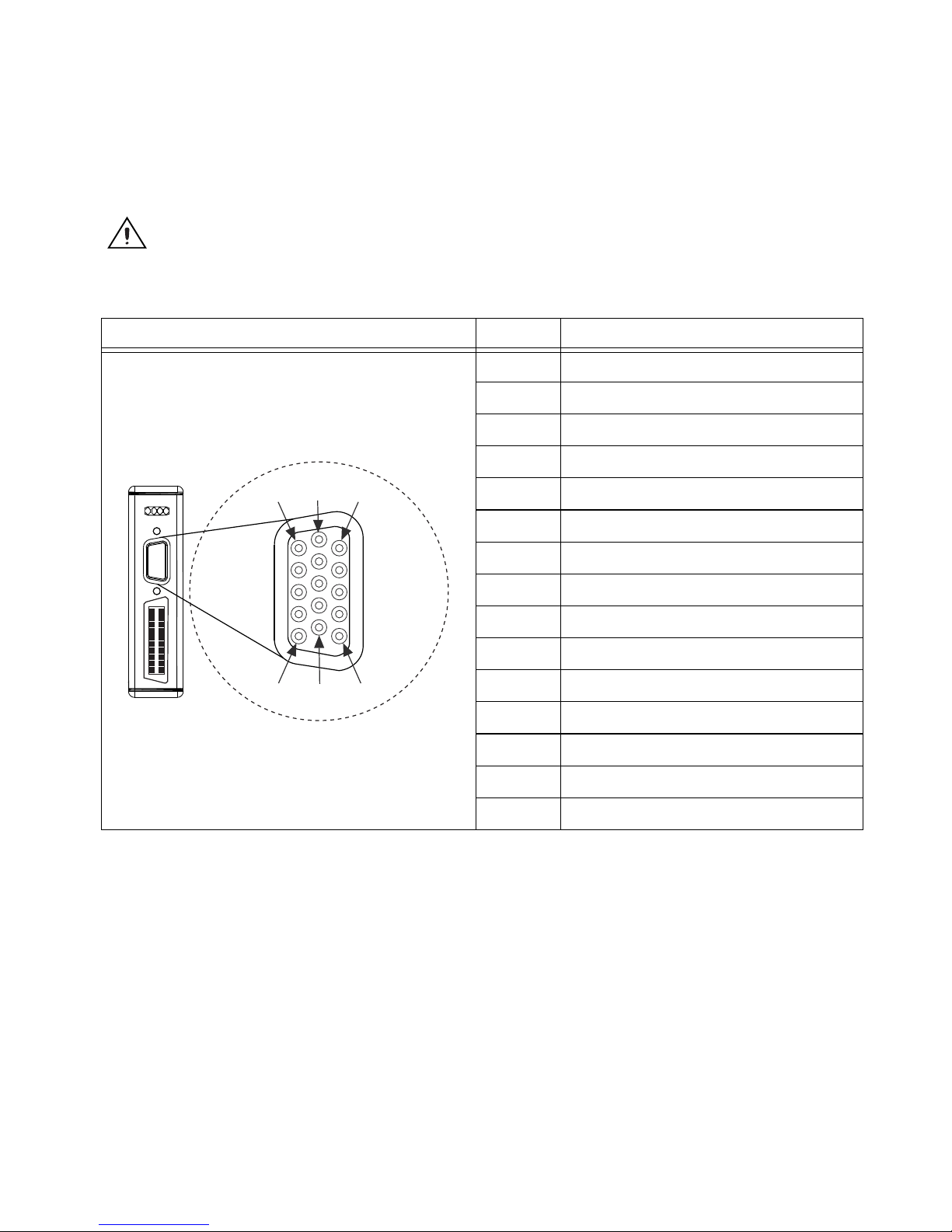
NI 9514 Connectors
1
6
11
5
10
15
Caution Do not connect anything to pins marked Reserved.
Table 2-2. NI 9514 DSUB Control Connector Pin Assignments
Connector Pin Signal
Chapter 2 Hardware Overview
Refer to Chapter 4, Accessory and Cable Connections, for cabling options
and connection accessory pin assignments.
1 Drive Command COM
2 Drive Enable
3 Reserved
4 Reserved
5 Reserved
6 Drive Command
7 COM
8 Digital Input 1
9 Reserved
10 Reserved
11 Reserved
12 V
sup
13 Reserved
14 COM
15 Reserved
© National Instruments Corporation 2-11 NI 951x User Manual
 Loading...