

Page 1
OPERATING INSTRUCTIONS AND SPECIFICATIONS
NI 9476E
32-Channel, 24 V Sourcing Digital Output Module
Page 2

This document describes how to use the National Instruments 9476E
and includes dimensions, connector assignments, and specifications for
the NI 9476E. Visit ni.com/info and enter rdsoftwareversion
to determine which software you need for the modules you are using.
For information about installing, configuring, and programming the
system, refer to the system documentation. Visit
enter
cseriesdoc for information about C Series documentation.
Caution National Instruments makes no electromagnetic
compatibility (EMC) or CE marking compliance claims
for the NI 9476E. The end-product supplier is responsible
for conformity to any and all compliance requirements.
Caution The NI 9476E must be installed inside a suitable
enclosure prior to use. Hazardous voltages may be present.
Caution Do not operate the NI 9476E in a manner not
specified in these operating instructions. Product misuse
can result in a hazard. You can compromise the safety
ni.com/info and
protection built into the product if the product is damaged
in any way. If the product is damaged, return it to National
Instruments for repair.
2 | ni.com | NI 9476E Operating Instructions and Specifications
Page 3
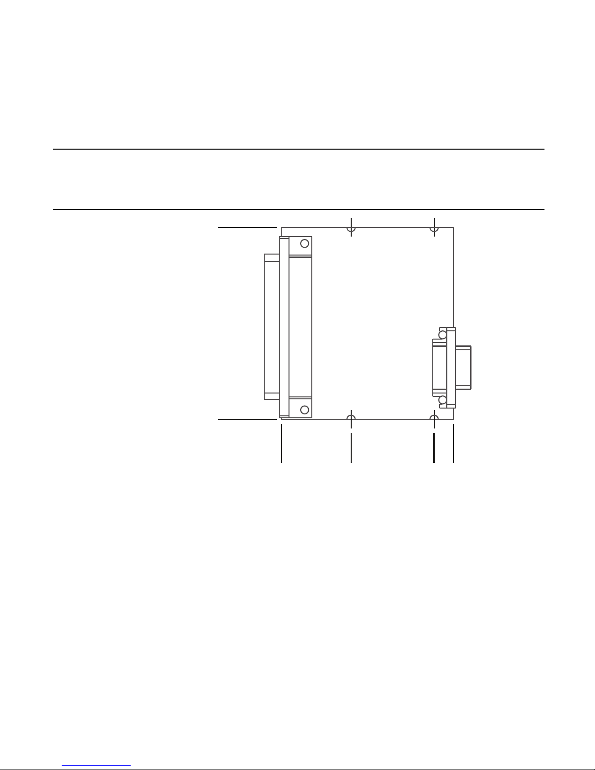
NI 9476E Dimensions
73.4 (2.89)
0.0 (0.00)
58.4 (2.30)
0.0 (0.00)
The following figure shows the dimensions of the NI 9476E.
Figure 1. NI 9476E Dimensions in Millimeters (Inches)
NI 9476E Operating Instructions and Specifications | © National Instruments | 3
Page 4

Connecting the NI 9476E
DO16
DO17
DO18
DO19
DO20
DO21
DO22
DO23
Vsup
Vsup
DO24
DO25
DO26
DO27
DO28
DO29
DO30
DO31
DO0
DO1
DO2
DO3
DO4
DO5
DO6
DO7
Vsup
Vsup
DO8
DO9
DO10
DO11
DO12
DO13
DO14
DO15
COM
1
2
3
4
5
6
7
8
9
10
11
12
13
14
15
16
17
18
19
20
21
22
23
24
25
26
27
28
29
30
31
32
33
34
35
36
37
The NI 9476E has a 37-pin DSUB connector that provides
connections for 32 digital output channels.
Figure 2. NI 9476E Pin Assignments
4 | ni.com | NI 9476E Operating Instructions and Specifications
Page 5
Each channel has a DO pin to which you can connect a digital input
device. The 32 digital output channels are internally referenced
to COM.
You must connect an external power supply to the NI 9476. The
power supply provides the current for the output channels. Connect
the positive lead of the power supply to the supply pin, V
sup
, and
the negative lead of the power supply to the common pin, COM.
Refer to the Specifications section for information about the power
supply voltage range.
Note The V
pins are internally connected. You can
sup
connect only one external voltage supply to the device.
Caution Do not remove or insert modules if the external
power supply connected to the V
and COM pins is
sup
powered on.
The NI 9476 has current sourcing outputs, meaning the DO pin is
driven to V
when the channel is turned on.
sup
NI 9476E Operating Instructions and Specifications | © National Instruments | 5
Page 6

You can directly connect the NI 9476 to a variety of industrial
NI 9476
+
_
COM
V
sup
Device
DO
External
Power
Supply
devices such as solenoids, motors, actuators, relays, and lamps.
Make sure the devices you connect to the NI 9476 are compatible
with the output specifications of the module. Refer to the
Specifications section for more information about the output
specifications.
Connect the device to DO and COM, and connect the external
power supply to V
Figure 3. Connecting a Device to the NI 9476
Caution To ensure a grounded connection, use shielded
I/O cables and tie the shield to the chassis ground.
and COM, as shown in Figure 3.
sup
6 | ni.com | NI 9476E Operating Instructions and Specifications
Page 7

Increasing Current Drive
Each channel has a continuous output current of 250 mA. If you
want to increase the output current to a device, you can connect
any number of channels together in parallel. For example, if you
want to drive 1 A of current, connect DO <0..3> in parallel as
shown in Figure 4. You must turn all parallel channels on and off
simultaneously so that the current on any single channel cannot
exceed the 250 mA rating.
Figure 4. Increasing the Current to a Device Connected to the NI 9476
V
sup
DO0
DO1
DO2
DO3
COM
NI 9476
NI 9476E Operating Instructions and Specifications | © National Instruments | 7
250 mA
250 mA
250 mA
250 mA
1 A
Device
External
+
_
Power
Supply
Page 8

Protecting the Module from Flyback Voltages
External
Power
Supply
NI 9476
+
_
COM
V
sup
Inductive
Device
DO
Flyback
Diode
If the module is switching an inductive or energy-storing device
such as a solenoid, motor, or relay, and the device does not have
flyback protection, install an external flyback diode as shown in
Figure 5.
Figure 5. Connecting a Flyback Diode to the NI 9476
8 | ni.com | NI 9476E Operating Instructions and Specifications
Page 9

I/O Protection
The NI 9476 is protected against overcurrent, inrush, and
short-circuit conditions in accordance with IEC 1131-2.
Understanding Protected Devices
Each channel on the NI 9476 has circuitry that protects it from
voltage and current surges resulting from short circuits.
Caution The NI 9476 can be damaged under overvoltage
and reverse bias voltage conditions. Check the voltage
specifications for all devices that you connect to the
NI 9476.
Excessive current through a DO pin causes the channel to go into
an overcurrent state. In an overcurrent state, the channel cycles off
and on until the short circuit is removed or the current returns to an
acceptably low level. Refer the Specifications section for typical
trip currents.
Each channel has a status line that indicates in software whether
the channel is in an overcurrent state. Refer to the software help for
information about reading output status.
NI 9476E Operating Instructions and Specifications | © National Instruments | 9
Page 10

Sleep Mode
This module supports a low-power sleep mode. Support for sleep
mode at the system level depends on the chassis that the module is
plugged into. Refer to the chassis manual for information about
support for sleep mode. If the chassis supports sleep mode, refer to
the software help for information about enabling sleep mode. Visit
ni.com/info and enter cseriesdoc for information about
C Series documentation.
Typically, when a system is in sleep mode, you cannot
communicate with the modules. In sleep mode, the system
consumes minimal power and may dissipate less heat than it does
in normal mode. Refer to the Specifications section for more
information about power consumption and thermal dissipation.
10 | ni.com | NI 9476E Operating Instructions and Specifications
Page 11

Specifications
The following specifications are typical for the range -40 to 70 °C
unless otherwise noted. All voltages are relative to COM unless
otherwise noted.
Output Characteristics
Number of channels .......................... 32 digital output channels
Output type ....................................... Sourcing
Output voltage (V
)........................... V
0
- (I0R0)
sup
Power-on output state ....................... Channels off
External power supply
voltage range (V
Continuous output current (I
)........................... 6 to 36 VDC
sup
) per channel
0
With 6 to 30 VDC
supply voltage ............................ 250 mA max
With 30 to 36 VDC
supply voltage ............................ 200 mA max
Output impedance (R
) ..................... 0.3 Ω max
0
NI 9476E Operating Instructions and Specifications | © National Instruments | 11
Page 12

Continuous overvoltage
protection (V
) ................................ up to 40 V max
sup
Reversed-voltage protection ............. None
Current limiting ................................ None
Short-circuit protection..................... Indefinitely protected when a
channel is shorted to COM or
to a voltage up to V
sup
Trip current for one channel
With all other channels
at rated current............................ 3 A typ
With all other channels off ......... 5 A typ
V
current consumption .................. 28 mA max
sup
Maximum update rate....................... 40 μs max
Propagation delay ............................. 500 μs max
12 | ni.com | NI 9476E Operating Instructions and Specifications
Page 13

MTBF ............................................... 1,091,425 hours at 25 °C;
Bellcore Issue 2, Method 1,
Case 3, Limited Part Stress
Method
Note Contact NI for Bellcore MTBF specifications
at other temperatures or for MIL-HDBK-217F
specifications.
Power Requirements
Power consumption from chassis
Active mode ............................... 250 mW max
Sleep mode ................................. 25 μW max
Thermal dissipation (at 70 °C)
Active mode ............................... 1.5 W max
Sleep mode ................................. 30 mW max
Physical Characteristics
If you need to clean the module, wipe it with a dry towel.
Weight............................................... 46 g (1.6 oz)
NI 9476E Operating Instructions and Specifications | © National Instruments | 13
Page 14

Safety
Maximum Voltage
1
Connect only voltages that are within the following limits.
V
-to-COM..................................... 36 VDC,
sup
Measurement Category 1
Measurement Category I is for measurements performed on
circuits not directly connected to the electrical distribution system
referred to as MAINS voltage. MAINS is a hazardous live electrical
supply system that powers equipment. This category is for
measurements of voltages from specially protected secondary
circuits. Such voltage measurements include signal levels, special
equipment, limited-energy parts of equipment, circuits powered by
regulated low-voltage sources, and electronics.
Caution Do not connect the NI 9476 to signals or use
for measurements within Measurement Categories II, III,
or IV.
1
The maximum voltage that can be applied or output between V
creating a safety hazard.
14 | ni.com | NI 9476E Operating Instructions and Specifications
sup
and COM without
Page 15

Caution Measurement Categories CAT I and CAT O
(Other) are equivalent. These test and measurement
circuits are not intended for direct connection to the
MAINS building installations of Measurement Categories
CAT II, CAT III, or CAT IV.
Isolation Voltages
Channel-to-channel........................... None
Channel-to-earth ground
Continuous ................................. 60 VDC,
Measurement Category I up
to 5,000 m altitude
Withstand
up to 2,000 m altitude ..........1,000 V
, verified by a 5 s
rms
dielectric withstand test
up to 5,000 m altitude ..........500 V
, verified by a 5 s
rms
dielectric withstand test
NI 9476E Operating Instructions and Specifications | © National Instruments | 15
Page 16

Safety Standards
This product is designed to meet the requirements of the following
standards of safety for electrical equipment for measurement,
control, and laboratory use:
• IEC 61010-1, EN 61010-1
• UL 61010-1, CSA 61010-1
Note For UL and other safety certifications, refer to the
product label or visit
ni.com/certification, search by
module number or product line, and click the appropriate
link in the Certification column.
Online Product Certification
Refer to the product Declaration of Conformity (DoC) for
additional regulatory compliance information. To obtain product
certifications and the DoC for this product, visit ni.com/
certification
click the appropriate link in the Certification column.
, search by module number or product line, and
16 | ni.com | NI 9476E Operating Instructions and Specifications
Page 17

Shock and Vibration
To meet these specifications, you must panel mount the system.
Operating vibration
Random (IEC 60068-2-64)......... 5 g
, 10 to 500 Hz
rms
Sinusoidal (IEC 60068-2-6) ....... 5 g, 10 to 500 Hz
Operating shock
(IEC 60068-2-27).............................. 30 g, 11 ms half sine,
50 g, 3 ms half sine,
18 shocks at 6 orientations
Environmental
Refer to the manual for the chassis you are using for more
information about meeting these specifications.
Operating temperature
(IEC 60068-2-1, IEC 60068-2-2) .....-40 to 85 °C
Note Measure the local ambient temperature by placing
thermocouples on both sides of the PCB, 0.2 in. (5 mm)
from the board surface. Avoid placing thermocouples next
NI 9476E Operating Instructions and Specifications | © National Instruments | 17
Page 18

to hot components such as the FPGA, processor, or near
board edges, which can cause inaccurate temperature
measurements.
Storage temperature
(IEC 60068-2-1, IEC 60068-2-2) .....-40 to 85 °C
Ingress protection.............................. IP 40
Operating humidity
(IEC 60068-2-56).............................. 10 to 90% RH,
noncondensing
Storage humidity
(IEC 60068-2-56).............................. 5 to 95% RH,
noncondensing
Pollution Degree ............................... 2
Maximum altitude............................. 5,000 m
Indoor use only.
Environmental Management
NI is committed to designing and manufacturing products in
an environmentally responsible manner. NI recognizes that
eliminating certain hazardous substances from our products is
beneficial to the environment and to NI customers.
18 | ni.com | NI 9476E Operating Instructions and Specifications
Page 19

For additional environmental information, refer to the Minimize
RoHS
˅
Ёᅶ᠋
National Instruments
ヺড়Ё⬉ᄤֵᙃ
ѻકЁ䰤ࠊՓ⫼ᶤѯ᳝ᆇ⠽䋼ᣛҸ
(RoHS)
DŽ݇Ѣ
National Instruments
Ё
RoHS
ড়㾘ᗻֵᙃˈ䇋ⱏᔩ
ni.com/environment/rohs_china
DŽ
(For information
about China RoHS compliance, go to
ni.com/
environment/rohs_china
.)
Our Environmental Impact web page at
ni.com/environment.
This page contains the environmental regulations and directives
with which NI complies, as well as other environmental
information not included in this document.
Waste Electrical and Electronic Equipment (WEEE)
EU Customers At the end of the product life cycle,
all products must be sent to a WEEE recycling center.
For more information about WEEE recycling centers,
National Instruments WEEE initiatives, and compliance
with WEEE Directive 2002/96/EC on Waste and
Electronic Equipment, visit
weee
.
ni.com/environment/
NI 9476E Operating Instructions and Specifications | © National Instruments | 19
Page 20

Worldwide Support and Services
The National Instruments website is your complete resource for
technical support. At
ni.com/support you have access to
everything from troubleshooting and application development
self-help resources to email and phone assistance from
NI Application Engineers.
Visit
ni.com/services for NI Factory Installation Services,
repairs, extended warranty, and other services.
Visit
ni.com/register to register your National Instruments
product. Product registration facilitates technical support and
ensures that you receive important information updates from NI.
A Declaration of Conformity (DoC) is our claim of compliance
with the Council of the European Communities using the
manufacturer’s declaration of conformity. This system affords the
user protection for electromagnetic compatibility (EMC) and
product safety. You can obtain the DoC for your product by visiting
ni.com/certification. If your product supports calibration,
you can obtain the calibration certificate for your product
at ni.com/calibration.
20 | ni.com | NI 9476E Operating Instructions and Specifications
Page 21

National Instruments corporate headquarters is located at
11500 North Mopac Expressway, Austin, Texas, 78759-3504.
National Instruments also has offices located around the world. For
telephone support in the United States, create your service request
at
ni.com/support or dial 1 866 ASK MYNI (275 6964). For
telephone support outside the United States, visit the Worldwide
Offices section of ni.com/niglobal to access the branch office
websites, which provide up-to-date contact information, support
phone numbers, email addresses, and current events.
Refer to the NI Trademarks and Logo Guidelines at ni.com/trademarks for more information on National
Instruments trademarks. Other product and company names mentioned herein are trademarks or trade names of
their respective companies. For patents covering National Instruments products/technology, refer to the appropriate
location: Help»Patents in your software, the
Notice at
third-party legal notices in the readme file for your NI product. Refer to the Export Compliance Information at
ni.com/legal/export-compliance for the National Instruments global trade compliance policy and
how to obtain relevant HTS codes, ECCNs, and other import/export data. NI MAKES NO EXPRESS OR IMPLIED
WARRANTIES AS TO THE ACCURACY OF THE INFORMATION CONTAINED HEREIN AND SHALL NOT BE LIABLE FOR
ANY ERRORS. U.S. Government Customers: The data contained in this manual was developed at private expense
and is subject to the applicable limited rights and restricted data rights as set forth in FAR 52.227-14,
DFAR 252.227-7014, and DFAR 252.227-7015.
© 2015 National Instruments. All rights reserved.
374958A-01 Feb15
ni.com/patents. You can find information about end-user license agreements (EULAs) and
patents.txt file on your media, or the National Instruments Patent
 Loading...