

Page 1

GETTING STARTED GUIDE
ni.com/manuals
DeutschFrançais
NI 9437
8-Channel, 250 V Sinking Digital Input Module
Page 2
This document explains how to connect the National
Instruments 9437.
Before You Begin Complete the hardware and software
installation procedures in your chassis documentation.
Note The guidelines in this document are specific to the
NI 9437. The other components in the system might not
meet the same safety ratings. Refer to the documentation
for each component in the system to determine the safety
and EMC ratings for the entire system.
Safety Guidelines
Operate the NI 9437 only as described in these operating
instructions.
Hot Surface This icon denotes that the component may
be hot. Touching this component may result in bodily
injury.
Caution Do not operate the NI 9437 in a manner not
specified in this manual. Product misuse can result in a
hazard. You can compromise the safety protection built
2 | ni.com | NI 9437 Getting Started Guide
Page 3

into the product if the product is damaged in any way. If
the product is damaged, return it to National Instruments
for repair.
Safety Guidelines for Hazardous Voltages
If hazardous voltages are connected to the module, take the
following precautions. A hazardous voltage is a voltage greater
than 42.4 Vpk or 60 VDC to earth ground.
Caution Ensure that hazardous voltage wiring is
performed only by qualified personnel adhering to local
electrical standards.
Caution Do not mix hazardous voltage circuits and
human-accessible circuits on the same module.
Caution Make sure that devices and circuits connected
to the module are properly insulated from human contact.
NI 9437 Getting Started Guide | © National Instruments | 3
Page 4
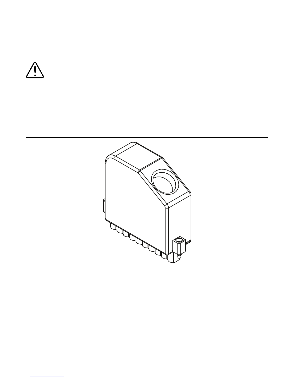
Caution When module terminals are hazardous voltage
LIVE (>42.4 V
/60 VDC), you must ensure that devices
pk
and circuits connected to the module are properly
insulated from human contact. You must use the NI 9932
connector backshell kit to ensure that the terminals are
not accessible.
Figure 1. NI 9932 Connector Backshell
4 | ni.com | NI 9437 Getting Started Guide
Page 5
Safety Voltages
Connect only voltages that are within the following limits.
Channel-to-COM, V
-to-COM ..... 300 VDC max
SUP
Isolation
Channel-to-channel .................... None
Channel-to-V
Channel-to-earth ground, V
......................... None
SUP
SUP
-to-earth ground,
COM-to-earth ground
Continuous ........................... 300 V
, Measurement
rms
Category II
Withstand ............................. 3,000 V, verified by a 5 s
dielectric withstand test
Measurement Category II is for measurements performed on
circuits directly connected to the electrical distribution system.
This category refers to local-level electrical distribution, such as
that provided by a standard wall outlet, for example, 115 V for U.S.
or 230 V for Europe.
Caution Do not connect the NI 9437 to signals or use for
measurements within Measurement Categories III or IV.
NI 9437 Getting Started Guide | © National Instruments | 5
Page 6

Electromagnetic Compatibility Guidelines
This product was tested and complies with the regulatory
requirements and limits for electromagnetic compatibility (EMC)
as stated in the product specifications. These requirements and
limits are designed to provide reasonable protection against
harmful interference when the product is operated in its intended
operational electromagnetic environment.
This product is intended for use in industrial locations. There is no
guarantee that harmful interference will not occur in a particular
installation, when the product is connected to a test object, or if the
product is used in residential areas. To minimize the potential for
the product to cause interference to radio and television reception
or to experience unacceptable performance degradation, install and
use this product in strict accordance with the instructions in the
product documentation.
Furthermore, any changes or modifications to the product not
expressly approved by National Instruments could void your
authority to operate it under your local regulatory rules.
Caution To ensure the specified EMC performance,
operate this product only with shielded cables and
accessories. Do not use unshielded cables or accessories
unless they are installed in a shielded enclosure with
6 | ni.com | NI 9437 Getting Started Guide
Page 7

properly designed and shielded input/output ports and
connected to the product using a shielded cable. If
unshielded cables or accessories are not properly installed
and shielded, the EMC specifications for the product are
no longer guaranteed.
Caution To ensure the specified EMC performance,
cable shields must be connected to the ground lug of the
carrier using a wire of minimum practical length.
Special Guidelines for Marine Applications
Some products are Lloyd’s Register (LR) Type Approved for
marine (shipboard) applications. To verify Lloyd’s Register
certification for a product, visit
ni.com/certification and
search for the LR certificate, or look for the Lloyd’s Register mark
on the product label.
Caution In order to meet the EMC requirements for
marine applications, install the product in a shielded
enclosure with shielded and/or filtered power and
input/output ports. In addition, take precautions when
designing, selecting, and installing measurement probes
and cables to ensure that the desired EMC performance is
attained.
NI 9437 Getting Started Guide | © National Instruments | 7
Page 8

Preparing the Environment
Ensure that you are using the NI 9437 in an environment that meets
the following specifications:
Operating temperature
(IEC 60068-2-1, IEC 60068-2-2) .....-40 °C to 70 °C
Operating humidity
(IEC 60068-2-56).............................. 10% to 90% RH,
noncondensing
Pollution Degree ............................... 2
Maximum altitude............................. 5,000 m
Indoor use only.
Note Refer to the NI 9437 Datasheet on ni.com/
manuals
8 | ni.com | NI 9437 Getting Started Guide
for complete specifications.
Page 9

Connecting the NI 9437
DI0
DI1
DI2
DI3
DI4
DI5
DI6
DI7
V
SUP
COM
0
1
2
3
4
5
6
7
8
9
0 3
47
The NI 9437 provides connections for 8 digital input channels.
Figure 2. NI 9437 Pinout
NI 9437 Getting Started Guide | © National Instruments | 9
Page 10

Connecting Sourcing-Output Devices
NI 9437
2/3
≥
+
–
External
Power
Supply
COM
VSUP
DI
Sourcing-Output
Device
You can connect sourcing-output devices to the NI 9437. You must
connect a supply voltage to the V
pin on the NI 9437. Input
SUP
channels on the NI 9437 read ON or OFF depending on the
threshold set by the V
2/3 of the supply voltage on the V
Figure 3. Connecting a Sourcing-Output Device
pin. The V
SUP
SUP
SUP
threshold is approximately
pin.
10 | ni.com | NI 9437 Getting Started Guide
Page 11

Connecting a Split-Rail Power Supply
NI 9437
2/3
≥
+
–
Bias
Resistors
Floating Power Supply
COM
VSUP
DI
Sourcing-Output
Device
You can connect a split-rail power supply to the NI 9437. A
split-rail power supply consists of a floating power supply that is
weakly centered around earth ground using bias resistors.
Figure 4. Connecting a Split-Rail Power Supply
Ground-Fault Protection
When using a floating or split-rail power supply, the NI 9437 can
tolerate a single ground fault from V
COM-to-earth ground, or DI-to-earth ground. The NI 9437 can
tolerate a single ground fault from V
COM-to-earth ground because of the isolation of the module. The NI
9437 can tolerate a single ground fault from DI-to-earth ground
NI 9437 Getting Started Guide | © National Instruments | 11
-to-earth ground,
SUP
-to-earth ground or
SUP
Page 12

because the threshold reference is 2/3 the supply voltage on the V
SUP
pin. With any one pin—V
, COM, or a single DI—shorted to earth
SUP
ground, the NI 9437 operates normally and returns valid data.
You can also use a power supply with the NI 9437 that requires a
connection to earth ground for normal operation. When using this
type of power supply, there is always a connection between COM
and earth ground and you will not have protection against ground
faults from V
-to-earth ground or from DI-to-earth ground.
SUP
LED Indicators
The NI 9437 has eight LEDs to display the ON/OFF state of the
eight channels. When an LED is lit, the corresponding channel is
ON and data is being read from the NI 9437. When an LED is dark,
the corresponding channel is OFF.
Note If V
is not connected, the LED does not
SUP
indicate the state of the channel.
12 | ni.com | NI 9437 Getting Started Guide
Page 13

Connection Considerations
Keep in mind the following requirements when connecting to the
NI 9437.
• The supply voltage to V
must be within the range of
SUP
24 VDC to 250 VDC.
• Output devices that you connect to the NI 9437 must be able to
source enough current to overcome the NI 9437 input load
(burden). The NI 9437 burden is dynamic and varies
depending on the input voltage. Refer to the NI 9437
Datasheet on
ni.com/manuals for more information about
dynamic burden current on the NI 9437.
• Output devices that you connect to the NI 9437 do not need to
sink current. The NI 9437 input load current pulls the input
voltage to a low value when the output device is open, high
impedance, or not connected.
• The NI 9437 is immune to capacitively coupled transients
when using the correct debounce time based on the supply
voltage and the amount of capacitance in your system. Refer to
the NI 9437 Datasheet on
information about debounce times.
• Connecting more than one wire to a single terminal on the
NI 9437 requires 2-wire ferrules to create a secure connection.
NI 9437 Getting Started Guide | © National Instruments | 13
ni.com/manuals for more
Page 14

Where to Go Next
Located at ni.com/manuals Installs with the software
CompactRIO NI CompactDAQ
RELATED INFORMATION
C Series Documentation
& Resources
ni.com/info cseriesdoc
NI 9437 Datasheet
NI-RIO Help
LabVIEW FPGA Help
NI 9437 Datasheet
NI-DAQmx Help
LabVIEW Help
Services
ni.com/services
14 | ni.com | NI 9437 Getting Started Guide
Page 15

Worldwide Support and Services
The National Instruments website is your complete resource for
technical support. At
ni.com/support you have access to
everything from troubleshooting and application development
self-help resources to email and phone assistance from
NI Application Engineers.
Visit
ni.com/services for NI Factory Installation Services,
repairs, extended warranty, and other services.
Visit
ni.com/register to register your National Instruments
product. Product registration facilitates technical support and
ensures that you receive important information updates from NI.
National Instruments corporate headquarters is located at
11500 North Mopac Expressway, Austin, Texas, 78759-3504.
National Instruments also has offices located around the world. For
telephone support in the United States, create your service request
at ni.com/support or dial 1 866 ASK MYNI (275 6964). For
telephone support outside the United States, visit the Worldwide
Offices section of
ni.com/niglobal to access the branch office
websites, which provide up-to-date contact information, support
phone numbers, email addresses, and current events.
NI 9437 Getting Started Guide | © National Instruments | 15
Page 16

Refer to the NI Trademarks and Logo Guidelines at ni.com/trademarks for more information on National
Instruments trademarks. Other product and company names mentioned herein are trademarks or trade names of
their respective companies. For patents covering National Instruments products/technology, refer to the appropriate
location: Help»Patents in your software, the
Notice at
third-party legal notices in the readme file for your NI product. Refer to the Export Compliance Information at
ni.com/patents. You can find information about end-user license agreements (EULAs) and
patents.txt file on your media, or the National Instruments Patent
ni.com/legal/export-compliance for the National Instruments global trade compliance policy and
how to obtain relevant HTS codes, ECCNs, and other import/export data. NI MAKES NO EXPRESS OR IMPLIED
WARRANTIES AS TO THE ACCURACY OF THE INFORMATION CONTAINED HEREIN AND SHALL NOT BE LIABLE FOR
ANY ERRORS. U.S. Government Customers: The data contained in this manual was developed at private expense
and is subject to the applicable limited rights and restricted data rights as set forth in FAR 52.227-14,
DFAR 252.227-7014, and DFAR 252.227-7015.
© 2014 National Instruments. All rights reserved.
376437A-01 Aug14
 Loading...