

Page 1
OPERATING INSTRUCTIONS
NI 9219
4-Channel, 24-Bit, Universal Analog Input Module
Page 2
These operating instructions describe how to use the National
Instruments 9219. For information about installing, configuring,
and programming the system, refer to the system documentation.
Vis it
ni.com/info and enter the info code rdsoftwareversion
to determine which software you need for the modules you are
using.
Note The safety guidelines and specifications in this
document are specific to the NI 9219. The other
components in the system might not meet the same safety
ratings and specifications. Refer to the documentation for
each component in the system to determine the safety
ratings and specifications for the entire system.
Safety Guidelines
Operate the NI 9219 only as described in these operating
instructions.
Hot Surface This icon denotes that the component may be
hot. Touching this component may result in bodily injury.
NI 9219 Operating Instructions 2 ni.com
Page 3
Safety Guidelines for Hazardous Voltages
If hazardous voltages are connected to the module, take the
following precautions. A hazardous voltage is a voltage greater
than 42.4 V
© National Instruments Corp. 3 NI 9219 Operating Instructions
or 60 VDC to earth ground.
pk
Caution Ensure that hazardous voltage wiring is
performed only by qualified personnel adhering to
local electrical standards.
Caution Do not mix hazardous voltage circuits and
human-accessible circuits on the same module.
Caution Make sure that devices and circuits connected to
the module are properly insulated from human contact.
Caution When module terminals are hazardous voltage
LIVE (>42.4 V
/60 VDC), you must ensure that devices
pk
and circuits connected to the module are properly insulated
from human contact. You must use the NI 9972 connector
backshell kit to ensure that the terminals are not accessible.
Page 4
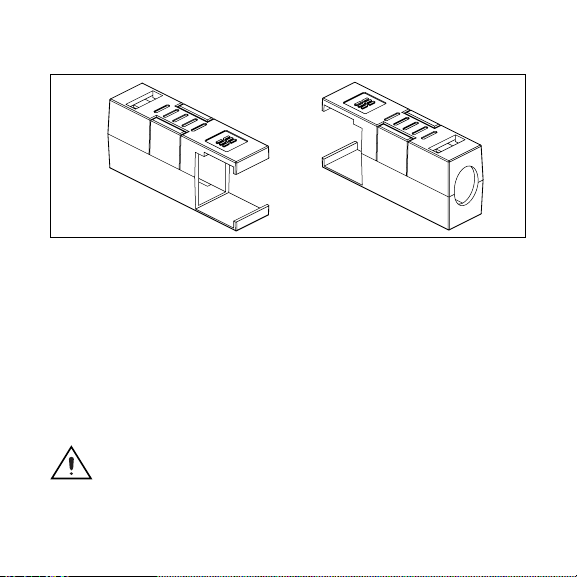
Figure 1 shows the NI 9972 connector backshell.
Figure 1. NI 9972 Connector Backshell
Safety Guidelines for Hazardous Locations
The NI 9219 is suitable for use in Class I, Division 2, Groups A, B,
C, D, T4 hazardous locations; Class I, Zone 2, AEx nC IIC T4
hazardous locations; and nonhazardous locations only. Follow
these guidelines if you are installing the NI 9219 in a potentially
explosive environment. Not following these guidelines may result
in serious injury or death.
Caution Do not disconnect I/O-side wires or connectors
unless power has been switched off or the area is known
to be nonhazardous.
NI 9219 Operating Instructions 4 ni.com
Page 5

Caution Do not remove modules unless power has been
switched off or the area is known to be nonhazardous.
Caution Substitution of components may impair
suitability for Class I, Division 2.
Caution For Zone 2 applications, install the system
in an enclosure rated to at least IP 54 as defined by
IEC 60529 and EN 60529.
Special Conditions for Marine Applications
Some modules are Lloyd’s Register (LR) Type Approved for
marine applications. To verify Lloyd’s Register certification, visit
ni.com/certification and search for the LR certificate, or
look for the Lloyd’s Register mark on the module.
Caution To meet radio frequency emission requirements
for marine applications, use shielded cables and install
the system in a metal enclosure. Suppression ferrites
must be installed on power supply inputs near power
entries to modules and controllers. Power supply and
module cables must be separated on opposite sides of
the enclosure and must enter/exit through opposing
enclosure walls.
© National Instruments Corp. 5 NI 9219 Operating Instructions
Page 6

Wiring the NI 9219
The NI 9219 has four 6-terminal connectors that provide
connections for four analog input channels. Connect the positive
signal of the signal source to the positive input signal terminal (HI)
and the negative signal of the signal source to the negative input
signal terminal (LO). Use the excitation terminals if your sensor
requires a separate excitation connection. Refer to Table 1 for the
signal names and Table 2 for the terminal assignments for each
mode. Refer to the NI 9219 Circuitry section for information about
connections in each mode.
NI 9219 Operating Instructions 6 ni.com
Page 7
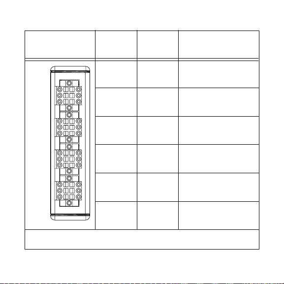
Table 1. Signal Names
Module Terminal
1 T+ TEDS Data
Signal
Name
Signal Description
Ch 0
Ch 1
Ch 2
Ch 3
1
2
3
1
2
3
1
2
3
1
2
3
4
5
6
4
5
6
4
5
6
4
5
6
2 T– TEDS COM
3 EX+/HI*Positive excitation or
input signal
4 HI Positive input signal
5 EX–/LO*Negative excitation or
input signal
6 LO Negative input signal
*
Depending on the mode, terminals 3 and 5 are either the excitation signals or the
input signals.
© National Instruments Corp. 7 NI 9219 Operating Instructions
Page 8

Table 2. Terminal Assignments
Terminal
Mode
1 2 3 4 5 6
Voltage T+ T– — HI LO —
Current T+ T– HI — LO —
4-Wire Resistance T+ T– EX+ HI EX– LO
2-Wire Resistance T+ T– HI — LO —
Thermocouple T+ T– — HI LO —
4-Wire RTD T+ T– EX+ HI EX– LO
3-Wire RTD T+ T– EX+ — EX– LO
Quarter-Bridge T+ T– HI — LO —
Half-Bridge T+ T– EX+ HI EX– —
Full-Bridge T+ T– EX+ HI EX– LO
Digital In T+ T– — HI LO —
Open Contact T+ T– HI — LO —
NI 9219 Operating Instructions 8 ni.com
Page 9
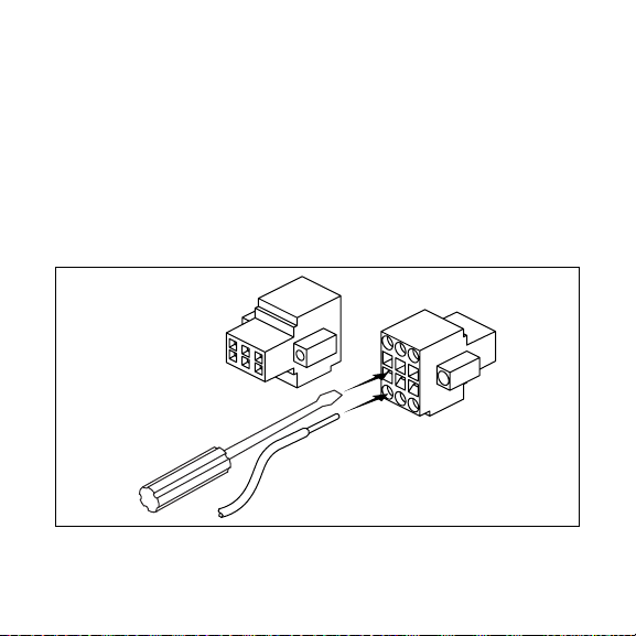
Connecting Wires to the NI 9219 Connectors
Use a flathead screwdriver with a blade smaller than 2.3 × 1.0 mm
(0.09 × 0.04 in.) to connect wires to the detachable spring-terminal
connectors. Insert the screwdriver into a spring clamp activation
slot and press a wire into the corresponding connector terminal,
then remove the screwdriver to clamp the wire into the terminal.
Refer to the Specifications section for more information about
spring-terminal wiring. Refer to Figure 2 for an illustration of
connecting wires to the NI 9219.
Figure 2. Connecting Wires to the NI 9219 Connectors
© National Instruments Corp. 9 NI 9219 Operating Instructions
Page 10

Wiring TEDS Channels
The NI 9219 supports only Class II
TEDS lines to
TEDS Data (T+) and TEDS COM (T–) and ensure
that neither T+ nor T– is tied in common to any of the signal inputs
(terminals 3 through 6) on the NI 9219. Visit ni.com/info and
enter the info code
rdteds for information about TEDS sensors.
TEDS sensors. Connect the two
Grounding and Shielding Considerations
You can connect ground-referenced or floating signal sources to
the NI 9219. If you make a floating connection between the signal
source and the NI 9219, make sure the voltages on the positive and
negative connections are within the channel-to-earth working
voltage range to ensure proper operation of the NI 9219. Refer to
the Specifications section for more information about operating
voltages and overvoltage protection.
Note For best signal quality, National Instruments
recommends using shielded cables and twisted pair
wiring whenever possible.
Figures 3 and 4 illustrate connecting grounded and floating signal
sources to the NI 9219 in Voltage mode.
NI 9219 Operating Instructions 10 ni.com
Page 11

Signal Source
+
V
SIG
–
V
Ground
SIG
Reference
Shielding
Twisted-Pair
Wiring
Figure 3. Connecting a Grounded Signal Source to the NI 9219
LO
HI
NI 9219
Signal Source
+
V
SIG
–
Shielding
Twisted-Pair
Wiring
LO
HI
NI 9219
Figure 4. Connecting a Floating Signal Source to the NI 9219
© National Instruments Corp. 11 NI 9219 Operating Instructions
Page 12

NI 9219 Timing Options
The NI 9219 supports four different timing options that are
optimized for different types of applications by using different
ADC conversion times. High Speed is optimized for high speed at
the expense of noise rejection, Best 60 Hz Rejection is optimized
for rejection of 60 Hz noise, Best 50 Hz Rejection is optimized for
rejection of 50 Hz noise, and High Resolution is optimized for
maximum overall noise rejection and provides good rejection of
50 Hz and 60 Hz noise. Refer to the Specifications section for more
information.
NI 9219 Circuitry
The NI 9219 is channel-to-channel isolated. Four 24-bit
analog-to-digital converters (ADCs) simultaneously sample all
four analog input channels. An excitation circuit is enabled for
all input modes that require excitation. The ADC and excitation
circuits are reconfigured in each mode to accommodate each type
of sensor. Refer to Figure 5 for an illustration of the input circuitry
for one channel of the NI 9219.
NI 9219 Operating Instructions 12 ni.com
Page 13

CHx
+
1
TEDS
–
2
3
6
FilterMUX
NI 9219
Isolated
ADC
Figure 5. Input Circuitry for One Channel
Voltage and Current Modes
In Voltage and Current modes, connect the signal source to the
NI 9219 across the HI and LO terminals. The current is computed
from the voltage that the ADC measures across an internal shunt
resistor. Refer to Figure 6 for an illustration of the connections.
HI
+
V
–
LO
Voltage/Digital In modes
ADC
NI 9219
HI
LO
R
SH
Current mode
I
ADC
NI 9219
Figure 6. Connections in Voltage, Current, and Digital In Modes
© National Instruments Corp. 13 NI 9219 Operating Instructions
Page 14

4-Wire Resistance and 4-Wire RTD Modes
4-Wire Resistance and 4-Wire RTD modes source a current, which
varies based on the resistance of the load, between the EX+ and
EX– terminals. The measured resistance is computed from the
resulting voltage reading. These modes are not affected by lead
wire resistance because a negligible amount of current flows across
the HI and LO terminals due to the high input impedance of the
ADC. Refer to Figure 7 for an illustration of the connections.
Wire
EX+
HI
RTD/
Resistor
Wire
Wire
Wire
LO
EX–
I
Figure 7. Connections in 4-Wire Resistance and 4-Wire RTD Modes
I
ADC
NI 9219
3-Wire RTD Mode
3-Wire RTD mode sources a current, which varies based on the
resistance of the load, between the EX+ and EX– terminals. This
mode compensates for lead wire resistance in hardware if all the
NI 9219 Operating Instructions 14 ni.com
Page 15

lead wires have the same resistance. A gain of 2x is applied to the
voltage across the negative lead wire and the ADC uses this voltage
as the negative reference to cancel the resistance error across the
positive lead wire. Refer to Figure 8 for an illustration of the
connections.
I
ADC
NI 9219
RTD
Wire
Wire
Wire
EX+
LO
EX–
I
x2
I
Figure 8. Connections in 3-Wire RTD Mode
2-Wire Resistance and Quarter-Bridge Modes
In 2-Wire Resistance and Quarter-Bridge modes, connect the
two ends of the resistor or gauge to the NI 9219 across the HI and
LO terminals. These modes source a current, which varies based on
the resistance of the load, between the HI and LO terminals. The
resulting resistance is computed from the voltage measurement.
2-Wire Resistance and Quarter-Bridge modes do not compensate
© National Instruments Corp. 15 NI 9219 Operating Instructions
Page 16

for lead wire resistance. Refer to Figure 9 for an illustration of the
connections.
Wire
HI
R
Wire
LO
ADC
I
I
NI 9219
Figure 9. Connections in 2-Wire Resistance and Quarter-Bridge Modes
Half-Bridge and Full-Bridge Modes
Half-Bridge and Full-Bridge modes use the internal voltage
excitation to set the input range of the ADC and return voltage
readings that are proportional to the excitation level. The internal
excitation voltage is nominally 2.5 V but it varies based on the
resistance of the sensor. Refer to the Specifications section for
more information about excitation levels.
In Half-Bridge mode, the HI input is referenced to EX–.
In Full-Bridge mode, the ADC reads the HI and LO inputs
differentially. Refer to Figure 10 for an illustration of the
connections.
NI 9219 Operating Instructions 16 ni.com
Page 17

Wire
EX+
R
1
R
2
R
4
R
3
Wire
HI
ADC
LO
1
EX–
NI 9219
1 The dotted line represents the portion of the circuit that is connected
only in Full-Bridge mode.
Figure 10. Connections in Half-Bridge and Full-Bridge Modes
Thermocouple Mode
In Thermocouple mode, connect the positive end of the
thermocouple to HI and the negative end of the thermocouple to
LO. This mode uses the ±125 mV range of the ADC to return a
voltage reading. Use shielded cables and twisted pair wiring and
ground the shielded cables. Each channel has a built-in thermistor
for cold-junction compensation (CJC) calculations. For improved
CJC sensor accuracy, operate the NI 9219 in a stable temperature
© National Instruments Corp. 17 NI 9219 Operating Instructions
Page 18

environment and avoid placing heat sources near the module
or its connectors. Refer to the Specifications section for more
information about accuracy. The NI 9219 does not support open
thermocouple detection. Refer to Figure 11 for an illustration of
the connections.
HI
+
TC
–
LO
Figure 11. Connections in Thermocouple Mode
ADC
NI 9219
Digital In Mode
Digital In mode has a 60 V unipolar threshold that you can set in
software. Refer to the software documentation for information
about setting this threshold. Digital In mode is supported only in
CompactRIO systems. Refer to Figure 6 for an illustration of the
connections.
Open Contact Mode
Open Contact mode sources a current between the HI and LO
terminals and determines if the two terminals are open or closed
based on the measured current through the terminals. When the
NI 9219 Operating Instructions 18 ni.com
Page 19

circuit is open, make sure no more than ±60 V is sourced across the
switch. Open Contact mode is supported only in CompactRIO
systems. Refer to Figure 12 for an illustration of the connections.
HI
LO
ADC
Figure 12. Connections in Open Contact Mode
I
NI 9219
Sleep Mode
This module supports a low-power sleep mode. Support for sleep
mode at the system level depends on the chassis that the module is
plugged into. Refer to the chassis documentation for information
about support for sleep mode. You can enable sleep mode in
software. Refer to the driver software documentation for more
information.
Typically, when a system is in sleep mode, you cannot
communicate with the modules. In sleep mode, the system
consumes minimal power and may dissipate less heat than it does
in normal mode. Refer to the Specifications section for more
information about power consumption and thermal dissipation.
© National Instruments Corp. 19 NI 9219 Operating Instructions
Page 20

Binary Data
NI 9219 modules in the system return calibrated binary data when
used in a CompactRIO chassis. For these modules, you can convert
the data to engineering units in software. Refer to the software
documentation for information about converting data. When used
in a CompactDAQ chassis, NI 9219 modules automatically return
the data in terms of engineering units. Refer to the software
documentation for more information.
Excitation Protection
The NI 9219 excitation circuit is protected from overcurrent and
overvoltage fault conditions. The circuit is automatically disabled
in the event of a fault condition. Whenever possible, channels
automatically recover after the fault is removed. Refer to the
software documentation for information on how an excitation fault
is displayed and handled.
Specifications
The following specifications are typical for the range –40 to 70 °C
unless otherwise noted.
NI 9219 Operating Instructions 20 ni.com
Page 21

Input Characteristics
Number of channels .......................... 4 analog input channels
ADC resolution................................. 24 bits
Type of ADC..................................... Delta-sigma (with analog
prefiltering)
Sampling mode ................................. Simultaneous
Type of TEDS supported ..................IEEE 1451.4 TEDS Class II
(Interface)
Mode input ranges
Mode Nominal Range(s) Actual Range(s)
Voltage ±60 V, ±15 V, ±4 V,
±1 V, ±125 mV
Current ±25 mA ±25 mA
4-Wire and 2-Wire Resistance 10 kΩ, 1 kΩ 10.5 kΩ, 1.05 kΩ
Thermocouple ±125 mV ±125 mV
4-Wire and 3-Wire RTD Pt 1000, Pt 100 5.05 kΩ, 505 Ω
Quarter-Bridge 350 Ω, 120 Ω 390 Ω, 150 Ω
Half-Bridge ±500 mV/V ±500 mV/V
© National Instruments Corp. 21 NI 9219 Operating Instructions
±60 V, ±15 V, ±4 V,
±1 V, ±125 mV
Page 22

Mode Nominal Range(s) Actual Range(s)
Full-Bridge ±62.5 mV/V,
±7.8 mV/V
Digital In — 0– 60 V
Open Contact — 1.05 kΩ
±62.5 mV/V,
±7.8125 mV/V
Conversion time, no channels in TC mode
High speed.................................. 10 ms for all channels
Best 60 Hz rejection ................... 110 ms for all channels
Best 50 Hz rejection ................... 130 ms for all channels
High resolution........................... 500 ms for all channels
Conversion time, one or more channels in TC mode
High speed.................................. 20 ms for all channels
Best 60 Hz rejection ................... 120 ms for all channels
Best 50 Hz rejection ................... 140 ms for all channels
High resolution........................... 510 ms for all channels
Overvoltage protection
Terminals 1 and 2 ....................... ±30 V
Terminals 3 through 6,
across any combination .............. ±60 V
NI 9219 Operating Instructions 22 ni.com
Page 23

Input impedance
Voltage and Digital In modes
(
±60 V, ±15 V, ±4 V) ..................... 1 MΩ
Current mode.............................. < 40 Ω
All other modes .......................... >1 GΩ
Accuracy
Gain Error
(% of
Reading)
Typ (25 °C, ±5 °C),
Mode, Range
Voltage, ±60 V ±0.3, ±0.4 ±20, ±50
Voltage, ±15 V ±0.3, ±0.4 ±60, ±180
Voltage, ±4 V ±0.3, ±0.4 ±240, ±720
Voltage, ±1 V ±0.1, ±0.18 ±15, ±45
Voltage/Thermocouple, ±125 mV ±0.1, ±0.18 ±120, ±360
Current, ±25 mA ±0.1, ±0.6 ±30, ±100
4-Wire and 2-Wire* Resistance, 10 kΩ ±0.1, ±0.5 ±120, ±320
4-Wire and 2-Wire* Resistance, 1 kΩ ±0.1, ±0.5 ±1200, ±3200
© National Instruments Corp. 23 NI 9219 Operating Instructions
Max (–40 to 70 °C)
Offset Error
(ppm of
Range)
Page 24

Gain Error
(% of
Reading)
Offset Error
(ppm of
Range)
Typ (25 °C, ±5 °C),
Mode, Range
Max (–40 to 70 °C)
4-Wire and 3-Wire RTD, Pt 1000 ±0.1, ±0.5 ±240, ±640
4-Wire and 3-Wire RTD, Pt 100 ±0.1, ±0.5 ±2400, ±6400
Quarter-Bridge, 350 Ω ±0.1, ±0.5 ±2400, ±6400
Quarter-Bridge, 120 Ω ±0.1, ±0.5 ±2400, ±6400
Half-Bridge, ±500 mV/V ±0.03, ±0.07 ±300, ±450
Full-Bridge, ±62.5 mV/V ±0.03, ±0.08 ±300, ±1000
Full-Bridge, ±7.8 mV/V ±0.03, ±0.08 ±2200, ±8000
*
2-Wire Resistance mode accuracy depends on the lead wire resistance. This table
assumes 0 Ω of lead wire resistance.
Cold-junction compensation
sensor accuracy ................................. ±1°C typ
NI 9219 Operating Instructions 24 ni.com
Page 25

Stability
Gain Drift
(ppm of
Mode, Range
Reading/°C)
Voltage, ±60 V ±20 ±0.2
Voltage, ±15 V ±20 ±0.8
Voltage, ±4 V ±20 ±3.2
Voltage, ±1 V ±10 ±0.2
Voltage/Thermocouple, ±125 mV ±10 ±1.6
Current, ±25 mA ±15 ±0.4
4-Wire and 2-Wire Resistance, 10 kΩ ±15 ±3
4-Wire and 2-Wire Resistance, 1 kΩ ±15 ±30
4-Wire and 3-Wire RTD, Pt 1000 ±15 ±6
4-Wire and 3-Wire RTD, Pt 100 ±15 ±60
Quarter-Bridge, 350 Ω ±15 ±120
Quarter-Bridge, 120 Ω ±15 ±240
Half-Bridge, ±500 mV/V ±3 ±20
© National Instruments Corp. 25 NI 9219 Operating Instructions
Offset Drift
(ppm of
Range/°C)
Page 26

Mode, Range
Gain Drift
(ppm of
Reading/°C)
Offset Drift
(ppm of
Range/°C)
Full-Bridge, ±62.5 mV/V ±3 ±20
Full-Bridge, ±7.8 mV/V ±3 ±20
Input noise in ppm of Range
rms
Conversion Time
Mode, Range
High
speed
Best
60 Hz
rejection
Best
50 Hz
rejection
High
reso-
lution
Voltage, ±60 V 7.6 1.3 1.3 0.5
Voltage, ±15 V 10.8 1.9 1.9 0.7
Voltage, ±4 V 10.8 2.7 2.7 1.3
Voltage, ±1 V 7.6 1.3 1.3 0.5
Voltage/Thermocouple,
10.8 1.9 1.9 1.0
±125 mV
Current, ±25 mA 10.8 1.9 1.9 1.0
NI 9219 Operating Instructions 26 ni.com
Page 27

Conversion Time
Mode, Range
4-Wire and 2-Wire Resistance,
Best
High
speed
60 Hz
rejection
4.1 1.3 0.8 0.3
Best
50 Hz
rejection
High
reso-
lution
10 kΩ
4-Wire and 2-Wire Resistance,
7.1 1.8 1.2 0.7
1 kΩ
4-Wire and 3-Wire RTD,
7.6 1.7 1.1 0.4
Pt 1000
4-Wire and 3-Wire RTD, Pt 100 10.8 1.9 1.9 0.9
Quarter-Bridge, 350 Ω 5.4 1.0 1.0 0.7
Quarter-Bridge, 120 Ω 5.4 1.0 1.0 0.7
Half-Bridge, ±500 mV/V 3.8 0.5 0.5 0.2
Full-Bridge, ±62.5 mV/V 5.4 1.0 1.0 0.8
Full-Bridge, ±7.8 mV/V 30 4.7 4.7 2.3
© National Instruments Corp. 27 NI 9219 Operating Instructions
Page 28

Input bias current .............................. <1 nA
INL.................................................... ±15 ppm
CMRR (f
= 60 Hz) .......................... >100 dB
in
NMRR
Best 60 Hz rejection ................... 90 dB at 60 Hz
Best 50 Hz rejection ................... 80 dB at 50 Hz
High resolution ........................... 65 dB at 50 Hz and 60 Hz
Excitation level for Half-Bridge and Full-Bridge modes
Mode Load Resistance (Ω) Excitation (V)
Half-Bridge 700 2.5
Half-Bridge 240 2.0
Full-Bridge 350 2.7
Full-Bridge 120 2.2
NI 9219 Operating Instructions 28 ni.com
Page 29

Excitation level for Resistance, RTD, and Quarter-Bridge modes
Load Resistance (Ω) Excitation (mV)
120 50
350 150
1 k 430
10 k 2200
MTBF ............................................... 384,716 hours at 25 °C;
Bellcore Issue 6, Method 1,
Case 3, Limited Part Stress
Method
Note Contact NI for Bellcore MTBF specifications
at other temperatures or for MIL-HDBK-217F
specifications.
Power Requirements
Power consumption from chassis
Active mode ...............................750 mW max
Sleep mode ................................. 25 μW max
© National Instruments Corp. 29 NI 9219 Operating Instructions
Page 30

Thermal dissipation (at 70 °C)
Active mode ...............................625 mW max
Sleep mode ................................. 25 μW max
Physical Characteristics
If you need to clean the module, wipe it with a dry towel.
Spring-terminal wiring...................... 18 to 28 AWG copper
conductor wire with 7 mm
(0.28 in.) of insulation
stripped from the end
Weight ............................................... 156 g (5.5 oz)
Safety
Safety Voltages
Connect only voltages that are within these limits.
Isolation
Channel-to-channel
Continuous ........................... 250 VAC,
Withstand ............................. 1390 VAC, verified by a 5 s
NI 9219 Operating Instructions 30 ni.com
Measurement Category II
dielectric withstand test
Page 31

Channel-to-earth ground
Continuous ........................... 250 VAC,
Measurement Category II
Withstand ............................. 2300 VAC, verified by a 5 s
dielectric withstand test
Measurement Category II is for measurements performed on
circuits directly connected to the electrical distribution system.
This category refers to local-level electrical distribution, such as
that provided by a standard wall outlet, for example, 115 V for U.S.
or 230 V for Europe. Do not connect the NI 9219 to signals or
use for measurements within Measurement Categories III or IV.
Safety Standards
This product is designed to meet the requirements of the following
standards of safety for electrical equipment for measurement,
control, and laboratory use:
• IEC 61010-1, EN 61010-1
• UL 61010-1, CSA 61010-1
Note For UL and other safety certifications, refer to the
product label or visit
© National Instruments Corp. 31 NI 9219 Operating Instructions
ni.com/certification, search
Page 32

by module number or product line, and click the
appropriate link in the Certification column.
Hazardous Locations
U.S. (UL) .......................................... Class I, Division 2,
Groups A, B, C, D, T4;
Class I, Zone 2,
AEx nC IIC T4
Environmental
National Instruments C Series modules are intended for indoor use
only but may be used outdoors if installed in a suitable enclosure.
Refer to the installation instructions for the chassis you are using
for more information about meeting these specifications.
Operating temperature
(IEC60068-2-1, IEC 60068-2-2) ......–40 to 70 °C
Storage temperature
(IEC60068-2-1, IEC 60068-2-2) ......–40 to 85 °C
Ingress protection.............................. IP 40
Operating humidity
(IEC 60068-2-56) ................................. 10 to 90% RH, noncondensing
Storage humidity
(IEC 60068-2-56).............................. 5 to 95% RH, noncondensing
NI 9219 Operating Instructions 32 ni.com
Page 33

Maximum altitude............................. 2,000 m
Pollution Degree (IEC 60664).......... 2
Shock and Vibration
To meet these specifications, you must panel mount the system.
Operating vibration
Random (IEC 60068-2-34)......... 5 g
, 10 to 500 Hz
rms
Sinusoidal (IEC 60068-2-6) ....... 5 g, 10 to 500 Hz
Operating shock
(IEC 60068-2-27).............................. 30 g, 11 ms half sine,
50 g, 3 ms half sine,
18 shocks at 6 orientations
Electromagnetic Compatibility
This product is designed to meet the requirements of the following
standards of EMC for electrical equipment for measurement,
control, and laboratory use:
• EN 61326 EMC requirements; Industrial Immunity
• EN 55011 Emissions; Group 1, Class A
• CE, C-Tick, ICES, and FCC Part 15 Emissions; Class A
© National Instruments Corp. 33 NI 9219 Operating Instructions
Page 34

Note For EMC compliance, operate this device with
shielded cabling.
CE Compliance
This product meets the essential requirements of applicable
European directives, as amended for CE markings, as follows:
• 73/23/EEC; Low-Voltage Directive (safety)
• 89/336/EEC; Electromagnetic Compatibility Directive (EMC)
Note Refer to the Declaration of Conformity (DoC) for
this product for any additional regulatory compliance
information. To obtain the DoC for this product, visit
ni.com/certification, search by module number or
product line, and click the appropriate link in the
Certification column.
Waste Electrical and Electronic Equipment (WEEE)
EU Customers At the end of their life cycle, all products
must be sent to a WEEE recycling center. For more
information about WEEE recycling centers and National
Instruments WEEE initiatives, visit
environment/weee.htm
NI 9219 Operating Instructions 34 ni.com
.
ni.com/
Page 35

Calibration
You can obtain the calibration certificate and information about
calibration services for the NI 9219 at
ni.com/calibration.
Calibration interval ........................... 1 year
Where to Go for Support
The National Instruments Web site is your complete resource for
technical support. At
ni.com/support you have access to
everything from troubleshooting and application development
self-help resources to email and phone assistance from
NI Application Engineers.
National Instruments corporate headquarters is located at
11500 North Mopac Expressway, Austin, Texas, 78759-3504.
National Instruments also has offices located around the world to
help address your support needs. For telephone support in the
United States, create your service request at
ni.com/support
and follow the calling instructions or dial 512 795 8248. For
telephone support outside the United States, contact your local
branch office:
Australia 1800 300 800, Austria 43 662 457990-0,
Belgium 32 (0) 2 757 0020, Brazil 55 11 3262 3599,
© National Instruments Corp. 35 NI 9219 Operating Instructions
Page 36

Canada 800 433 3488, China 86 21 5050 9800,
Czech Republic 420 224 235 774, Denmark 45 45 76 26 00,
Finland 385 (0) 9 725 72511, France 01 57 66 24 24,
Germany 49 89 7413130, India 91 80 41190000,
Israel 972 3 6393737, Italy 39 02 413091, Japan 81 3 5472 2970,
Korea 82 02 3451 3400, Lebanon 961 (0) 1 33 28 28,
Malaysia 1800 887710, Mexico 01 800 010 0793,
Netherlands 31 (0) 348 433 466, New Zealand 0800 553 322,
Norway 47 (0) 66 90 76 60, Poland 48 22 3390150,
Portugal 351 210 311 210, Russia 7 495 783 6851,
Singapore 1800 226 5886, Slovenia 386 3 425 42 00,
South Africa 27 0 11 805 8197, Spain 34 91 640 0085,
Sweden 46 (0) 8 587 895 00, Switzerland 41 56 2005151,
Taiwan 886 02 2377 2222, Thailand 662 278 6777,
Turkey 90 212 279 3031, United Kingdom 44 (0) 1635 523545
National Instruments, NI, ni.com, and LabVIEW are trademarks of National Instruments Corporation. Refer to the
Terms of Use section on
product and company names mentioned herein are trademarks or trade names of their respective companies.
For patents covering National Instruments products, refer to the appropriate location: Help»Patents in your software,
patents.txt file on your CD, or ni.com/patents.
the
© 2007 National Instruments Corp. All rights reserved.
374473D-01 Jun07
ni.com/legal for more information about National Instruments trademarks. Other
 Loading...