

Page 1
NI 6711/6713/6731/6733
C
ALIBRATIONPROCEDURE
Introduction
This document contains step-by-step instructions for calibrating
National Instruments 6711/6713/6731/6733 for PCI/PXI/CompactPCI
analog output (AO) devices. Use this calibration procedure in conjunction
with the
for calibrating NI 6711/6713/6731/6733 devices.
ni671xCal.dll
file, which contains specific functions required
Refer to
Note
ni671xCal.dll
ni.com/support/calibrat/mancal.htm
file.
What Is Calibration?
Calibration consists of verifying the measurement accuracy of a device
and adjusting for any measurement error. Verification is measuring the
performance of the device and comparing these measurements to the
factory specifications. During calibration, you supply and read voltage
levels using external standards, then you adjust the module calibration
constants. The new calibration constants are stored in the EEPROM.
The calibration constants are loaded from memory as needed to adjust
for the error in the measurements taken by the device.
Why Should You Calibrate?
The accuracy of electronic components drifts with time and temperature,
which can affect measurement accuracy as the device ages. Calibration
restores these components to their specified accuracy and ensures that the
device still meets NI standards.
for a copy of the
CVI™, LabVIEW™, National Instruments™, NI™, ni.com™, and NI-DAQ™ are trademarks of National Instruments
Corporation. Product and company names mentioned herein are trademarks or trade names of their respective
companies. For patents covering National Instruments products, refer to the appropriate location: Help»Patents in your
software, the patents.txt file on your CD, or ni.com/patents.
ni.com
© 2002 National Instruments Corp. All rights reserved.
May 2002
370555A-01
Page 2

How Often Should You Calibrate?
The measurement requirements of your application determine how often
the NI 6711/6713/6731/6733 must be calibrated to maintain accuracy.
NI recommends that you perform a complete calibration at least once every
year. You can shorten this interval to 90 days or six months based on the
demands of your application.
Calibration Options: External Versus Internal
The NI 6711/6713/6731/6733 has two calibration options: an internal,
or self-calibration, and an external calibration.
Internal Calibration
Internal calibration is a much simpler calibration method that does not rely
on external standards. In this method, the device calibration constants are
adjusted with respect to a high-precision voltage source on the
NI 6711/6713/6731/6733. This type of calibration is used after the device
has been calibrated with respect to an external standard. However, external
variables such as temperature can still affect measurements. The new
calibration constants are defined with respect to the calibration constants
created during an external calibration, ensuring that the measurements can
be traced back to the external standards. In essence, internal calibration is
similar to the auto-zero function found on a digital multimeter (DMM).
External Calibration
External calibration requires using a high-precision DMM. During external
calibration, the DMM supplies and reads voltages from the device.
Adjustments are made to the device calibration constants to ensure that the
reported voltages fall within the device specifications. The new calibration
constants are then stored in the device EEPROM. After the onboard
calibration constants have been adjusted, the high-precision voltage source
on the device is adjusted. An external calibration provides a set of
calibration constants that you can use to compensate for the error in the
measurements taken by the NI 6711/6713/6731/6733.
NI 6711/6713/6731/6733 Calibration Procedure 2 ni.com
Page 3

Equipment and Other Test Requirements
This section describes the equipment, test conditions, documentation,
and software you need to calibrate the NI 6711/6713/6731/6733.
Test Equipment
To calibrate the NI 6711/6713/6731/6733, you need a high-precision
DMM that is at least 10 ppm (0.001%) accurate. NI recommends that you
use the Agilent 3458A DMM for calibration.
If you do not have an Agilent 3458A DMM, use the accuracy specifications
to select a substitute calibration standard.
If you do not have custom connection hardware, you may need a connector
block such as the NI CB-68 and a cable such as the SH6868-D1. These
components give you easy access to the individual pins on the 68-pin
I/O connector.
Test Conditions
Follow these guidelines to optimize connections and test conditions during
calibration:
• Keep connections to the NI 6711/6713/6731/6733 short. Long cables
and wires act as antennae, picking up extra noise, which can affect
measurements.
• Use shielded copper wire for all cable connections to the device.
• Use twisted-pair wire to eliminate noise and thermal offsets.
• Maintain a temperature between 18 and 28 °C. To operate the module
at a specific temperature outside this range, calibrate the device at that
temperature.
• Keep relative humidity below 80%.
• Allow a warm-up time of at least 15 minutes to ensure that the
measurement circuitry is at a stable operating temperature.
Software
Because the NI 6711/6713/6731/6733 is a PC-based measurement device,
you must have the proper device driver installed in the calibration system
before attempting calibration. For this calibration procedure, you need
NI-DAQ version 6.9.2 or earlier installed on the calibration computer.
NI-DAQ, which configures and controls the NI 6711/6713/6731/6733,
is available at
© National Instruments Corporation 3 NI 6711/6713/6731/6733 Calibration Procedure
ni.com/downloads
.
Page 4

NI-DAQ supports a number of programming languages, including
LabVIEW, LabWindows/CVI, Microsoft Visual C++, Microsoft Visual
Basic and Borland C++. When you install the driver, you only need to
install support for the programming language that you intend to use.
You also need copies of the
ni671xCal.h
The DLL provides calibration functionality that does not reside in
NI-DAQ, including the ability to protect the calibration constants, update
the calibration date, and write to the factory calibration area. You can
access the functions in this DLL through any 32-bit compiler. The factory
calibration area and the calibration date should only be modified by a
metrology laboratory or another facility that maintains traceable standards.
files.
ni671xCal.dll,ni671xCal.lib
,and
Configuring the NI 6711/6713/6731/6733
The NI 6711/6713/6731/6733 must be configured in NI-DAQ, which
automatically detects the device. The following steps briefly explain how
to configure the device in NI-DAQ. Refer to the NI 671X/673X User
Manual for detailed installation instructions. You can install this manual
when you install NI-DAQ.
1. Power down the computer.
2. Install the NI 6711/6713/6731/6733 in an available slot.
3. Power on the computer.
4. Launch Measurement & Automation Explorer (MAX).
5. Configure the NI 6711/6713/6731/6733 device number.
6. Click Test Resources to ensure that the NI 6711/6713/6731/6733 is
properly working.
The NI 6711/6713/6731/6733 is now configured.
Note
After a device is configured in MAX, the device is assigned a device number, which
is used in each of the function calls to identify which DAQ device to calibrate.
Writing the Calibration Procedure
The calibration procedure in the Calibrating the NI 6711/6713/6731/6733
section provides step-by-step instructions on calling the appropriate
calibration functions. These calibration functions are C function calls from
NI-DAQ that are also valid for Microsoft Visual Basic and Microsoft
Visual C++ programs. Although LabVIEW VIs are not discussed in this
procedure, you can program in LabVIEW using the VIs that have similar
names to the NI-DAQ function calls in this procedure. Refer to the
NI 6711/6713/6731/6733 Calibration Procedure 4 ni.com
Page 5

Documentation
Flowcharts section for illustrations of the code used at each step of the
calibration procedure.
Often you must follow a number of compiler-specific steps to create an
application that uses NI-DAQ. Refer to the NI-DAQ User Manual for PC
Compatibles at
each of the supported compilers.
Many of the functions listed in the calibration procedure use variables that
are defined in the
include the
variable definitions, you can examine the function call listings in the
NI-DAQ documentation and the
values are required.
For information about NI-DAQ, refer to the following documentation:
• NI-DAQ Function Reference Help
(Start»Programs»National Instruments»NI-DAQ»NI-DAQ Help)
• NI-DAQ User Manual for PC Compatibles at
These two documents provide detailed information about using NI-DAQ.
The function reference help includes information on the functions in
NI-DAQ. The user manual provides instructions on installing and
configuring DAQ devices and detailed information on creating
applications that use NI-DAQ. These documents are the primary references
for writing the calibration utility. For further information on the device you
are calibrating, you may also want to install the device documentation.
ni.com/manuals
nidaqcns.h
nidaqcns.h
file in the code. If you do not want to use these
for details about the required steps for
file. To use these variables, you must
nidaqcns.h
file to determine what input
ni.com/manuals
Calibrating the NI 6711/6713/6731/6733
To calibrate the NI 6711/6713/6731/6733, complete the following steps:
1. Verify the performance of the NI 6711/6713/6731/6733. This step,
which is described in the Verifying the Performance of the
NI 6711/6713/6731/6733 section, confirms whether the device is in
specification prior to adjustment.
2. Adjust the NI 6711/6713/6731/6733 calibration constants with respect
to a known voltage source. This step is described in the Adjusting the
NI 6711/6713/6731/6733 section.
3. Re-verify the performance to ensure that the NI 6711/6713/6731/6733
is operating within its specifications after adjustment.
© National Instruments Corporation 5 NI 6711/6713/6731/6733 Calibration Procedure
Page 6

Verifying the Performance of the NI 6711/6713/6731/6733
Verification determines how well the device is meeting its specifications.
The verification procedure is divided into the major functions of the device.
Throughout the verification process, refer to the tables in the Specifications
section to see if the device needs adjustment.
Verifying Analog Output
This procedure verifies the AO performance of the
NI 6711/6713/6731/6733. NI recommends testing all channels of the
device. However, to save time, you can test only the channels used in your
application. Make sure that you have read the Equipment and Other Test
Requirements section before starting this procedure.
1. Disconnect all cables to the device. Make sure the device is not
connected to any circuits other than those specified by the calibration
procedure.
2. To internally calibrate the device, call the
function with the following parameters set as indicated:
• calOP set to
• setOfCalConst set to
• calRefVolts set to
ND_SELF_CALIBRATE
ND_USER_EEPROM_AREA
0
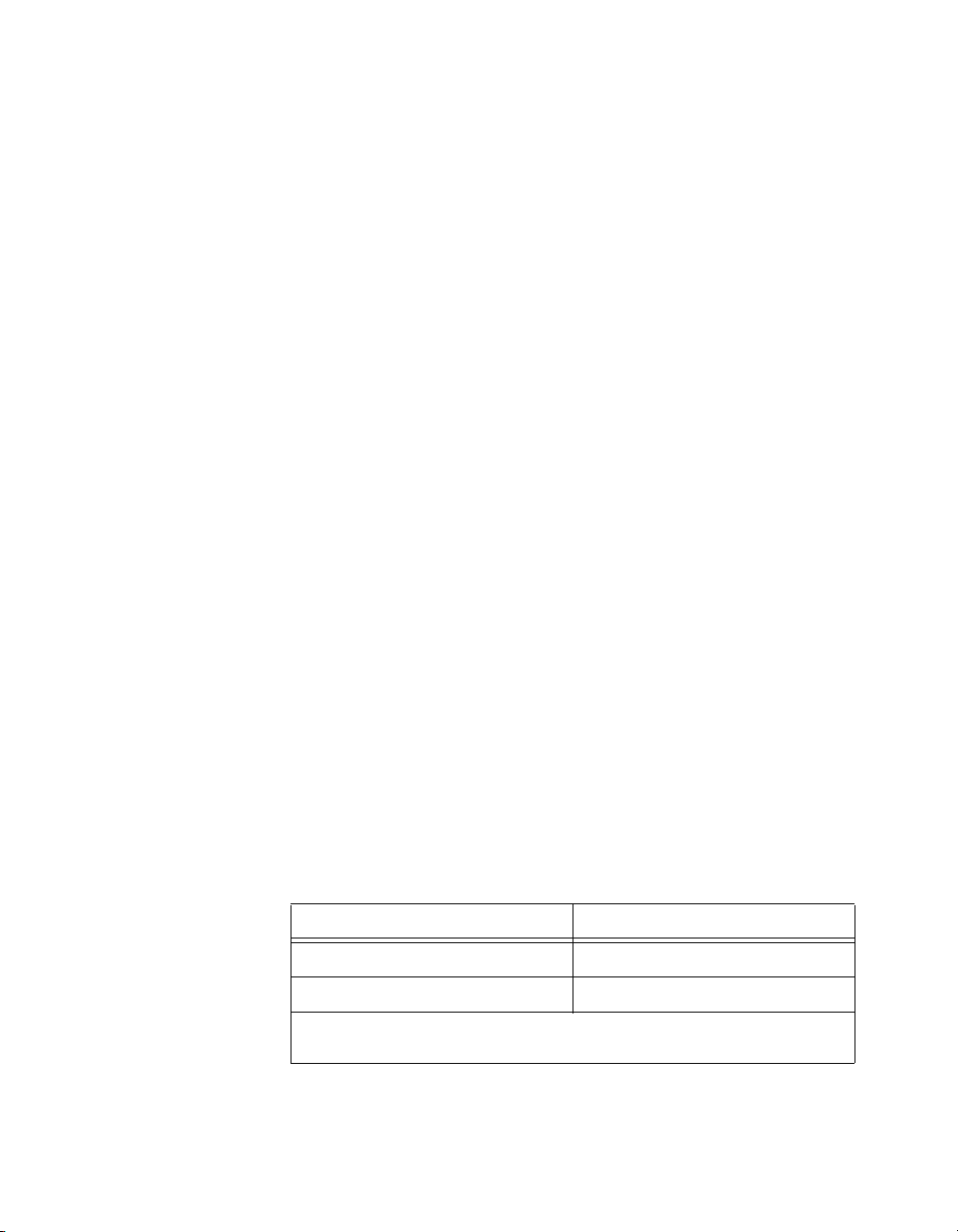
3. Connect the DMM to DAC0OUT as shown in Table 1.
Calibrate_E_Series
Table 1. Connecting the DMM to DAC0OUT
Output Channel DMMPositiveInput DMM Negative Input
DAC0OUT DAC0OUT (pin 22) AOGND (pin 56)
DAC1OUT DAC1OUT (pin 21) AOGND (pin 55)
DAC2OUT DAC2OUT (pin 57) AOGND (pin 23)
DAC3OUT DAC3OUT (pin 25) AOGND (pin 58)
DAC4OUT DAC4OUT (pin 60) AOGND (pin 26)
DAC5OUT DAC5OUT (pin 28) AOGND (pin 61)
DAC6OUT DAC6OUT (pin 30) AOGND (pin 63)
DAC7OUT DAC7OUT (pin 65) AOGND (pin 63)
Note: Pin numbers are given for 68-pin I/O connectors only. If you are using a 50-pin
I/O connector, refer to the device user manual for signal connection locations.
4. Refer to the table from the Specifications section that corresponds
to the device you are verifying. This specification table shows all
acceptable settings for the device.
NI 6711/6713/6731/6733 Calibration Procedure 6 ni.com
Page 7

5. Call
AO_Configure
to configure the device for the appropriate device
number, channel, and output polarity (the NI 6711/6713/6731/6733
devices support only bipolar output range). Use channel 0 as the
channel to verify. Read the remaining settings from the specification
table for the device.
6. Call
AO_VWrite
to update the AO channel with the appropriate
voltage. The voltage value is in the specification table.
7. Compare the resulting value shown by the DMM to the upper and
lower limits on the specification table. If the value falls between these
limits, the device has passed the test.
8. Repeat steps 3 through 5 until you have tested all values.
9. Disconnect the DMM from DAC0OUT, and reconnect it to the next
channel, making the connections from Table 1.
10. Repeat steps 3 through 9 until you have verified all channels.
11. Disconnect the DMM from the device.
You have now verified the AO channels of the device.
Verifying the Performance of the Counter
This procedure verifies the performance of the counter. The
NI 6711/6713/6731/6733 devices have only one timebase to verify, so you
only need to verify counter 0. Because you cannot adjust this timebase, you
can only verify the performance of counter 0. Make sure that you have read
the Equipment and Other Test Requirements section, and then follow this
procedure:
1. Connect the counter positive input to GPCTR0_OUT (pin 2) and the
counter negative input to DGND (pin 35).
Note
Pin numbers are given for 68-pin I/O connectors only. If you are using a 50-pin
I/O connector, refer to the device documentation for signal connection locations.
2. Call
GPCTR_Control
with action set to
ND_RESET
to place the
counter in a default state.
3. Call
GPCTR_Set_Application
ND_PULSE_TRAIN_GNR
to configure the counter for pulse-train
with application set to
generation.
4. Call
GPCTR_Change_Parameter
with paramID set to
ND_COUNT_1
and paramValue set to2to configure the counter to output a pulse
with an off time of 100 ns.
5. Call
GPCTR_Change_Parameter
with paramID set to
ND_COUNT_2
and paramValue set to2to configure the counter to output a pulse
with an on time of 100 ns.
© National Instruments Corporation 7 NI 6711/6713/6731/6733 Calibration Procedure
Page 8
6. Call
Select_Signal
ND_GPCTR0_OUTPUT
pin on the device I/O connector.
7. Call
GPCTR_Control
generation of the square wave. The device begins to generate a 5 MHz
square wave when
GPCTR_Control
8. Compare the value read by the counter to the test limits shown in the
appropriate table in the Specifications section. If the value falls
between these limits, the device has passed this test.
9. Disconnect the counter from the device.
You have now verified the device counter.
Adjusting the NI 6711/6713/6731/6733
This procedure adjusts the AO calibration constants. At the end of each
calibration procedure, these new constants are stored in the factory area
of the device EEPROM. An end-user cannot modify these values, which
provides a level of security that ensures users do not accidentally access or
modify any calibration constants adjusted by the metrology laboratory.
This step in the calibration process calls functions in NI-DAQ and in
the
ni671x.dll
ni671x.dll
1. Disconnect all cables to the device. Make sure the device is not
connected to any circuits other than those specified by the calibration
procedure.
2. To internally calibrate the device, call the
function with the following parameters set as indicated:
• calOP set to
• setOfCalConst set to
• calRefVolts set to
3. Connect the calibrator to the device according to Table 2.
. For further information on the functions in the
, refer to the comments in the
ND_SELF_CALIBRATE
with signal and source set to
to route the counter signal to the GPCTR0_OUT
with action set to
ND_PROGRAM
to start the
completes execution.
ni671x.h
Calibrate_E_Series
ND_USER_EEPROM_AREA
0
file.
Table 2. Connecting the Calibrator to the Device
6711/6713/6731/6733 Pins Calibrator
EXTREF (pin 20) Output High
AOGND (pin 54) Output Low
Pin numbers are given for 68-pin connectors only. If you are using a 50-pin connector,
refer to the device documentation for signal connection locations.
NI 6711/6713/6731/6733 Calibration Procedure 8 ni.com
Page 9

4. To find out the date of the last calibration, call
is included in the
device was last calibrated.
5. Set the calibrator to output a voltage of 5.0 V.
6. Call
Note
If the voltage supplied by the source does not maintain a steady 5.0 V, you receive
an error.
Calibrate_E_Series
indicated:
• calOP set to
• setOfCalConst set to
• calRefVolts set to
ni671x.dll
ND_EXTERNAL_CALIBRATE
5.0
. CalDate stores the date when the
with the following parameters set as
ND_USER_EEPROM_AREA
Get_Cal_Date
,which
Specifications
Using the Tables
7. Call
8. Disconnect the calibrator from the device.
The device is now adjusted with respect to the external source. After
the device is adjusted, you can verify the AO operation by repeating the
Verifying Analog Output section.
The following tables are accuracy specifications to use when verifying and
adjusting the NI 6711/6713/6731/6733. The tables show the specifications
for 1-year and 24-hour calibration intervals.
The following definitions describe how to use the specification tables in
this section.
Copy_Const
factory-protected portion of the EEPROM. This function also updates
the calibration date.
to copy the new calibration constants to the
Range
Range refers to the maximum allowable voltage range of an input or output
signal. For example, if a device is configured in bipolar mode with a range
of 20 V, the device can sense signals between +10 and –10 V.
Polarity
Polarity refers to the positive and negative voltages of the input signal that
can be read. Bipolar means the device can read both positive and negative
voltages. Unipolar means that the device can read only positive voltages.
© National Instruments Corporation 9 NI 6711/6713/6731/6733 Calibration Procedure
Page 10

Tes t Poi nt
The Test Point is the voltage value that is input or output for verification
purposes. This value is broken down into Location and Value. Location
refers to where the test value fits within the test range. Pos FS refers to
positive full-scale, and Neg FS refers to negative full-scale. Value refers to
the voltage to be verified, and Zero refers to the outputting of zero volts.
24-Hour Ranges
The 24-Hour Range column contains the upper limits and lower limits for
the test point value. If the device has been calibrated in the last 24 hours,
the test point value should fall between the upper and lower limit values.
These limit values are expressed in volts.
1-Year Ranges
The 1-Year Range column contains the upper limits and lower limits for the
test point value. If the device has been calibrated in the last year, the test
point value should fall between the upper and lower limit values. These
limits are expressed in volts.
Counters
Because you cannot adjust the resolution of the counter/timers, these values
do not have a 1-year or 24-hour calibration period. However, the test point
and upper and lower limits are provided for verification purposes.
Table 3. Analog Output for the NI 6711/6713
Te st P o i nt 24-Hour Ranges 1-Year Ranges
Lower
Range (V) Polarity
0 Bipolar Zero 0.0 –0.0059300 0.0059300 –0.0059300 0.0059300
20 Bipolar Pos FS 9.9900000 9.9822988 9.9977012 9.9818792 9.9981208
20 Bipolar Neg FS –9.9900000 –9.9977012 –9.9822988 –9.9981208 –9.9818792
Range (V) Polarity
0 Bipolar Zero 0.0 –0.0010270 0.0010270 –0.0010270 0.0010270
20 Bipolar Pos FS 9.9900000 9.9885335 9.9914665 9.9883636 9.9916364
20 Bipolar Neg FS –9.9900000 –9.9914665 –9.9885335 –9.9916364 –9.9883636
NI 6711/6713/6731/6733 Calibration Procedure 10 ni.com
Location Va lu e ( V)
Table 4. Analog Output for the NI 6731/6733
Te st P o i nt 24-Hour Ranges 1-Year Ranges
Location Va lu e ( V)
Limit (V)
Lower
Limit (V)
Upper
Limit (V)
Upper
Limit (V)
Lower
Limit (V)
Lower
Limit (V)
Upper
Limit (V)
Upper
Limit (V)
Page 11

Flowcharts
These flowcharts show the appropriate NI-DAQ function calls for
verifying and adjusting the NI 6711/6713/6731/6733. Refer to the
Calibrating the NI 6711/6713/6731/6733 section, the NI-DAQ Function
Reference Help (Start»Programs»National Instruments»NI-DAQ»
NI-DAQ Help), and the NI-DAQ User Manual for PC Compatibles at
ni.com/manuals
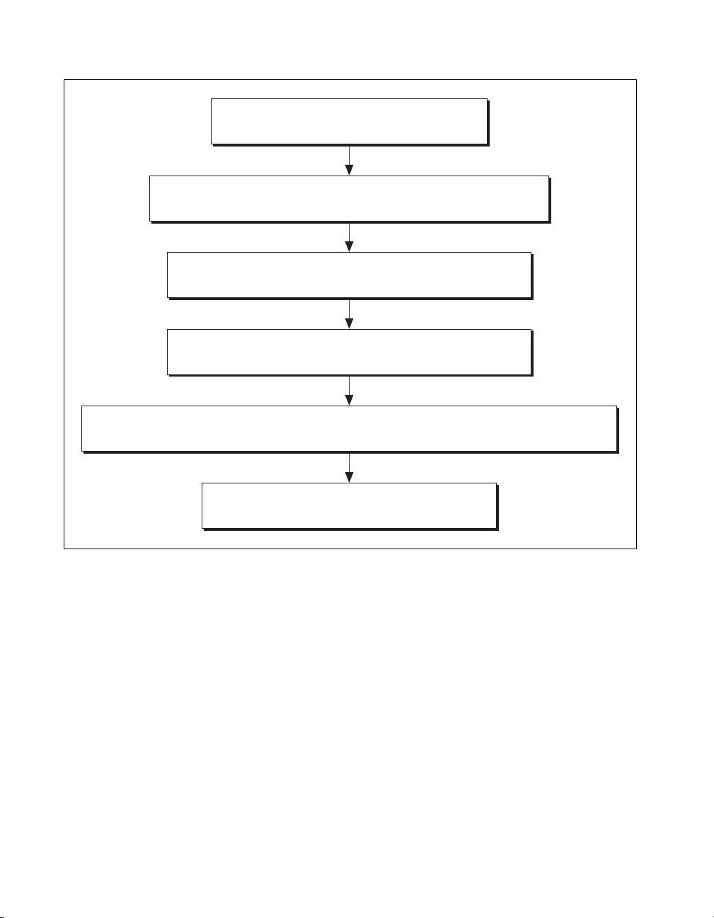
Verifying Analog Output
AO_Configure (deviceNumber,channel,outputPolarity,0,10,0)
Table 5. Counter
Set Point (MHz) Upper Limit (MHz) Lower Limit (MHz)
5 4.9995 5.0005
for additional information on the software structure.
From the specification table for the product,
determine the channel and voltage to verify.
AO_VWrite (deviceNumber,channel,voltage)
Repeat with next channel.
Figure 1. Verifying Analog Output
© National Instruments Corporation 11 NI 6711/6713/6731/6733 Calibration Procedure
Page 12
Verifying the Counter
GPCTR_Control (deviceNumber,0,ND_RESET)
GPCTR_Set_Application (deviceNumber,0,ND_PULSE_TRAIN_GNR)
GPCTR_Change_Parameter (deviceNumber,0,ND_COUNT_1,2)
GPCTR_Change_Parameter (deviceNumber,0,ND_COUNT_2,2)
Select_Signal (deviceNumber,ND_GPCTR0_OUTPUT,ND_GPCTR0_OUTPUT,ND_LOW_TO_HIGH)
GPCTR_Control (deviceNumber,0,ND_PROGRAM)
Figure 2. Verifying the Counter
NI 6711/6713/6731/6733 Calibration Procedure 12 ni.com
Page 13

Adjusting the NI 6711/6713/6731/6733
Calibrate_E_Series (deviceNumber,ND_SELF_CALIBRATE,ND_USER_EEPROM_AREA,0)
Get_Cal_Date (deviceNumber,*CalDate)
Calibrate_E_Series (deviceNumber,ND_EXTERNAL_CALIBRATE,ND_USER_AREA,5.0)
Copy_Const (deviceNumber)
Figure 3. Adjusting the NI 6711/6713/6731/6733
© National Instruments Corporation 13 NI 6711/6713/6731/6733 Calibration Procedure
 Loading...