

Page 1
USER GUIDE
NI 653x Cable Adapter
The NI 653x cable adapter interfaces with National Instruments high-speed
digital I/O (DIO) devices. The cable adapter provides an easy way to
connect the Very High Density Connector Interface (VHDCI) connectors,
labeled as Digital Data & Control, on the newer NI 6535/6536/6537
devices to the 68-pin DAQ connectors found on older NI 6533/6534
accessories and fixturing. The 653x cable adapter is also compatible with
the NI 654x and NI 655x digital pattern generator/analyzer devices.
For best signal integrity, NI recommends using the NI 6535/6536/6537
devices with newer accessories such as the NI CB-2162 and NI SMB-2163.
This guide explains how to set up and use the NI 653x cable adapter.
Contents
What You Need to Get Started ............................................................... 2
Related Documentation........................................................................... 2
Parts Locator Diagram ............................................................................ 3
Installing Cables......................................................................................4
Removing the NI 653x Cable Adapter from its Enclosure ..................... 5
Connecting Signals ................................................................................. 6
Custom Wiring Example ................................................................. 11
Specifications .......................................................................................... 13
Digital I/O ........................................................................................ 13
Traces............................................................................................... 13
Power ...............................................................................................13
Physical............................................................................................ 13
Where to Go for Support......................................................................... 14
Page 2

What You Need to Get Started
To set up and use the NI 653x cable adapter, you need the following items:
❑ NI SHC68-C68-D2 or NI C68-C68-D4 cable assembly
(for NI 6535/6536/6537/654x/655x devices)
❑ Compatible NI high-speed digital I/O device
(NI 6535/6536/6537/654x/655x)
❑ (Optional) 22- to 26-gauge wire
❑ (Optional) The documentation included with the NI high-speed DIO
device and the driver software included with your device
❑ (Optional) NI 6533 or NI 6534 supported terminal block
Related Documentation
National Instruments high-speed DIO devices ship with several documents
designed to familiarize you with different aspects of the device. The titles
and location of the documents vary based on the driver that supports the
NI device, but you should have the following types of documentation:
• Getting Started Guide—This printed document should be the first
thing you read. Its purpose is to guide you through setting up the
high-speed DIO device and configuring it to generate or acquire your
first samples.
• Help—This online document provides more in-depth information
about the hardware capabilities of the high-speed DIO device, theory
of operation discussion, and information on programming flow and
software reference.
• Specifications—This printed document provides specifications for the
NI hardware.
Vis it
ni.com/manuals for the most current documentation.
You also may have documentation for any application development
environment (ADE) you are using.
NI 653x Cable Adapter User Guide 2 ni.com
Page 3

Parts Locator Diagram
Refer to Figure 1 to locate connectors and components on the NI 653x
cable adapter.
1
2
8
7
6
1 Enclosure Base
2 Jacksockets (M2.5 Screw, #2-56 Socket)
3 68-Pin DAQ Connector
4 Enclosure Top Cover
3
4
5
653X CABLE ADAPTER
NATIONAL
INSTRUMENTS
Remove screws on this side of
enclosure to access terminals.
5 M2.5 x 6 mm Philips Flathead Countersunk Screws
6 Terminal Connectors
7 VHDCI Connector
8 #2-56 Custom Screw
Figure 1. NI 653x Cable Adapter Parts Locator Diagram
© National Instruments Corporation 3 NI 653x Cable Adapter User Guide
Page 4

Installing Cables
An SHC68-C68-D2 or C68-C68-D4 cable connects the NI 653x cable
adapter to the NI high-speed DIO device. Figure 2 shows how to install the
cable.
1
DIGITAL DATA & CONTROL
653x
NI PCIe-
3
2
enclosure to access terminals.
Remove screws on this side of
653X CABLE ADAPTER
INSTRUMENTS
NATIONAL
4
1 PC Chassis with NI High-Speed DIO Device
2 Cable Assembly
3 Cable Jackscrews
4 NI 653x Cable Adapter
Figure 2. Connecting a SHC68-C68-D2 or C68-C68-D4 Cable
to the NI 653x Cable Adapter
Caution
Before connecting the cable, disconnect power from the NI device and any other
connected hardware to prevent damage to the hardware and personal injury. NI is not liable
for damage resulting from improper connections.
Refer to Figure 2 as you complete the following steps to install the cable
adapter:
1. Insert the cable into the cable adapter.
2. Tighten the cable jackscrews.
Caution Before attaching any cables or accessories, install the NI high-speed DIO device.
Refer to the Getting Started Guide that shipped with your device for instructions on
installing the device.
NI 653x Cable Adapter User Guide 4 ni.com
Page 5
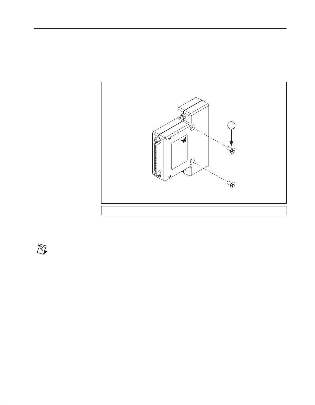
Removing the NI 653x Cable Adapter from its Enclosure
You will need to remove the NI 653x cable adapter from its enclosure to
connect signals. To remove the cable adapter from its enclosure, complete
the following steps:
1. Remove the screws from the cable adapter enclosure top cover,
as shown in Figure 3.
1
653X CABLE ADAPTER
NATIONAL
INSTRUMENTS
Remove screws on this side of
enclosure to access terminals.
1 M2.5 x 6 mm Philips Flathead Countersunk Screws
Figure 3. Remove Screws from the Enclosure
2. Remove the enclosure top cover.
Note Be sure to remove the screws from side with the NI logo label, as shown in Figure 3.
© National Instruments Corporation 5 NI 653x Cable Adapter User Guide
Page 6

Connecting Signals
The NI 653x cable adapter provides connectivity to up to 32 of the
single-ended DIO channels of an NI high-speed DIO device. Each DIO,
PFI, and clock channel of the NI high-speed DIO device connects to a
corresponding pin on the NI 653x cable adapter. The 32 DIO channels are
directly connected between the two bulk connectors. PFI <0..5> from the
NI 6535/6536/6537 VHDCI connector are connected to a 6-position screw
terminal. PFI <0..7> from the NI 6533/6534 68-pin DAQ connector are
connected to an 8-position screw terminal.
PFI channels must be manually connected through screw terminals for
flexibility and to ensure correct signal routing. You can make connections
between the PFI channels using 22- to 26-gauge wire.
The NI 6533/6534 devices have specific applications for PFI channels and
thus require custom wiring to be compatible. An example of how to make
these connections is provided in the Custom Wiring Example section.
Figure 4 shows the screw terminal locations on the NI 653x cable adapter.
C1
W1
GND +5V
J3
J2
6535/6/7 PFI
J1 J4
5
4
3
2
1
0
6533/4
PFI
7
6
5
4
3
2
1
0
Figure 4. NI 653x Signal Connections
NI 653x Cable Adapter User Guide 6 ni.com
Page 7

Note Refer to the help file for your device for information about the number of available
DIO channels on your device. DIO <20..31> or PFI_0 may not be applicable to your
device.
Figures 5 and 6 show pinouts for the VHDCI connector and 68-pin DAQ
connector, respectively.
DIO 31
GND
DIO 29
GND
DIO 27
GND
DIO 25
RESERVED
DIO 23
GND
DIO 21
GND
DIO 19
GND
DIO 17
GND
DIO 15
GND
DIO 13
GND
DIO 11
GND
DIO 9
GND
DIO 7
PFI 1
DIO 5
GND
DIO 3
PFI 3
DIO 1
GND
DDC CLK OUT/PFI_4
GND
1
2
3
4
5
6
7
8
9
10
11
12
13
14
15
16
17
18
19
20
21
22
23
24
25
26
27
28
29
30
31
32
33
34
35
DIO 30
36
GND
37
DIO 28
38
GND
39
DIO 26
40
GND
41
DIO 24
42
GND
43
DIO 22
44
GND
45
DIO 20
46
GND
47
DIO18
48
GND
49
DIO 16
50
GND
51
DIO 14
52
RESERVED/PFI_0
53
DIO 12
54
GND
55
DIO 10
56
GND
57
DIO 8
58
GND
59
DIO 6
60
RESERVED
61
DIO 4
62
GND
63
DIO 2
64
PFI 2
65
DIO 0
66
GND
67
STROBE/PFI_5
68
GND
Figure 5. VHDCI Connector Pinout (NI SHC68-C68-D2 or NI C68-C68-D4 Cable)
© National Instruments Corporation 7 NI 653x Cable Adapter User Guide
Page 8

+5 V
PFI 2
PFI 6
PFI 0
PFI 4
PFI 5
PFI 1
PFI 7
PFI 3
P0.0
GND
P0.3
P0.4
GND
P0.7
P1.0
P1.1
GND
R GND
GND
P1.6
P1.7
P2.0
GND
P2.3
P2.4
GND
P2.7
P3.0
GND
P3.3
P3.4
GND
P3.7
10
11
12
13
14
15
16
17
18
19
20
21
22
23
24
25
26
27
28
29
30
31
32
33
34
1
35
R GND
2
36
GND
3
37
GND
4
38
D PULL
5
39
GND
6
40
C PULL
7
41
GND
8
42
GND
9
43
R GND
44
P0.1
45
P0.2
46
GND
47
P0.5
48
P0.6
49
GND
50
GND
51
P1.2
52
P1.3
53
P1.4
54
P1.5
55
GND
56
R GND
57
P2.1
58
P2.2
59
GND
60
P2.5
61
P2.6
62
GND
63
P3.1
64
P3.2
65
GND
66
P3.5
67
P3.6
68
GND
Figure 6. 68-pin DAQ Connector (NI 6533/6534 Fixture or Accessory)
NI 653x Cable Adapter User Guide 8 ni.com
Page 9

Table 1 describes the VHDCI signals shown in Figure 5. Table 2 describes
the DAQ connector signals shown in Figure 6.
Table 1. VHDCI Connector Pinout Descriptions (NI 6535/6536/6537/654x/655x)
Pin Signal Description Connection
DIO <0..31> Bidirectional digital data channels 0 through 31. P0 <0..7>, P1 <0..7>,
P2 <0..7>, or P3 <0..7>
on a 68-pin DAQ
connector
PFI <0..5> Programmable functional interface (PFI) channels 0
through 5.
6-position screw
terminal (J4)
GND Ground reference for signals. —
RESERVED These channels are reserved for system use.
—
Do not connect signals to these channels.
Note Refer to your device documentation for supported channels.
Table 2. DAQmx Connector Pinout Descriptions (NI 6533/6534)
Pin Signal Description Connection
P0 <0..7> Bidirectional digital data port 0 channels 0 through 7. VHDCI DIO <0..7>
P1 <0..7> Bidirectional digital data port 1 channels 0 through 7. VHDCI DIO <8..15>
P2 <0..7> Bidirectional digital data port 2 channels 0 through 7. VHDCI DIO <16..23>
P3 <0..7> Bidirectional digital data port 3 channels 0 through 7. VHDCI DIO <24..31>
PFI <0..7> Programmable functional interface (PFI) channels 0
through 7.
8-position screw
terminal (J3)
+ 5 V DC power Unpopulated W1
C PULL,
Power on state control NC
DPULL
Note The NI 6535/6536/6537/654x/655x does not provide +5 V. If your fixtures require
this, access to the +5 V signal on the DAQ connector is provided through the unpopulated
W1 through-hole solder pad.
© National Instruments Corporation 9 NI 653x Cable Adapter User Guide
Page 10

Caution Connections that exceed any of the maximum ratings for the NI 653x cable
adapter or the NI high-speed DIO device can damage the device and the computer.
Maximum input ratings are provided in the Specifications section and in the specifications
document that shipped with the NI high-speed DIO device. NI is not liable for any damage
resulting from such signal connections.
Table 3 shows the relationship between PFI channels and the termination
sockets.
Table 3. PFI Screw Terminals
Connector Channel Socket
VHDCI
PFI <0..5> J4
(NI 6535/6536/6537/654x/655x)
68-Pin DAQ Connector
PFI <0..7> J3
(NI 6533/6534)
Note Refer to the help file for your device for information about the number of available
DIO channels on your device. DIO <20..31> or PFI_0 may not be applicable to your
device.
NI 653x Cable Adapter User Guide 10 ni.com
Page 11

Custom Wiring Example
You can use different wiring schemes to connect the PFI channels in
multiple configurations. This section describes a burst handshaking
example using an NI 653x cable adapter to provide compatibility between
an NI 6533/6534 and an NI 6535/6536/6537 where the fixture is
configured to work with the NI 6533/6534. Without changing the fixture
setup, the adapter and software can be changed to maintain functionality.
The NI 653x cable adapter can be configured using 22- to 26-gauge wire as
shown in Figure 7.
C1
W1
GND +5V
ACK/Ready for Transfer
CLK OUT
REQ/Pause
J3
J2
6535/6/7 PFI
J1 J4
5
4
3
2
1
0
6533/4
PFI
7
6
5
4
3
2
1
0
Figure 7. Example Connectivity
This custom wiring results in the signal assignments shown in the following
table.
Table 4. Example Connections
VHDCI
NI 6535/6536/6537
68-Pin DAQ
NI 6533/6534
PFI_0 PFI_2 (REQ/Pause)
PFI_1 PFI_6 (ACK/Ready for Transfer)
PFI_4 PFI_4 (CLK OUT)
© National Instruments Corporation 11 NI 653x Cable Adapter User Guide
Page 12

A burst handshaking example using the NI 6533/6534 can be coded in
LabVIEW as shown in Figure 8.
Figure 8. NI 6533/6534 Burst Handshaking Application
Figure 9 shows the changes made to this LabVIEW VI to accommodate the
NI 653x cable adapter connections and provide compatibility with the
previous application using an NI 6535/6536/6537 instead of an
NI 6533/6534.
Figure 9. NI 653x Burst Handshaking Application with NI 653x Cable Adapter and
NI 6535/6536/6537 (Changes Circled)
NI 653x Cable Adapter User Guide 12 ni.com
Page 13

Specifications
Digital I/O
Traces
Power
Physical
VHDCI DIO channels............................ 32, single-ended
VHDCI control channels........................ 6, single-ended
DAQ DIO channels................................ 32, single-ended
DAQ control channels............................ 8, single-ended
Type ....................................................... Matched length to 100 mils
AC impedance........................................ 50 Ω
Maximum voltage rating........................5.5 V
Dimensions............................................. 62.7 × 69.3 × 16.7 mm
(2.47 × 2.73 × 0.66 in.)
I/O connectors ........................................ 68-pin VHDCI connector,
6 position screw terminal,
8 position screw terminal,
68-pin DAQ connector
Recommended wire gage ....................... 22-26 AWG
Recommended torque
for screw terminals................................. 0.3 N-m (2.7 lb-in)
Recommended torque
for cover screws ..................................... 0.23 N-m (2.0 lb-in)
Weight.................................................... 60 g (2.1 oz)
Caution When connected to other test objects, this product may cause radio interference.
In a residential environment, the user may be required to take adequate measures to reduce
the radio interference.
© National Instruments Corporation 13 NI 653x Cable Adapter User Guide
Page 14

Where to Go for Support
The National Instruments Web site is your complete resource for technical
support. At
troubleshooting and application development self-help resources to email
and phone assistance from NI Application Engineers.
National Instruments corporate headquarters is located at
11500 North Mopac Expressway, Austin, Texas, 78759-3504.
National Instruments also has offices located around the world to help
address your support needs. For telephone support in the United States,
create your service request at
instructions or dial 512 795 8248. For telephone support outside the United
States, contact your local branch office:
Australia 1800 300 800, Austria 43 0 662 45 79 90 0,
Belgium32027570020, Brazil551132623599,
Canada 800 433 3488, China 86 21 6555 7838,
Czech Republic 420 224 235 774, Denmark 45 45 76 26 00,
Finland3850972572511, France330148142424,
Germany 49 0 89 741 31 30, India 91 80 41190000,
Israel 972 0 3 6393737, Italy 39 02 413091, Japan 81 3 5472 2970,
Korea820234513400, Lebanon96101332828,
Malaysia 1800 887710, Mexico 01 800 010 0793,
Netherlands 31 0 348 433 466, New Zealand 0800 553 322,
Norway 47 0 66 90 76 60, Poland 48 22 3390150,
Portugal 351 210 311 210, Russia 7 095 783 68 51,
Singapore 1800 226 5886, Slovenia 386 3 425 4200,
South Africa 27 0 11 805 8197, Spain 34 91 640 0085,
Sweden460858789500, Switzerland41562005151,
Taiwan 886 02 2377 2222, Thailand 662 278 6777,
United Kingdom 44 0 1635 523545
ni.com/support you have access to everything from
ni.com/support and follow the calling
NI 653x Cable Adapter User Guide 14 ni.com
Page 15

National Instruments, NI, ni.com, and LabVIEW are trademarks of National Instruments Corporation.
Refer to the Terms of Use section on ni.com/legal for more information about National
Instruments trademarks. Other product and company names mentioned herein are trademarks or trad e
names of their respective companies. For patents covering National Instruments products, refer to the
appropriate location: Help»Patents in your software, the patents.txt file on your CD, or
ni.com/patents.
© 2006 National Instruments Corporation. All rights reserved.
374435A-01 Aug06
 Loading...