

Page 1

GETTING STARTED GUIDE
NI High-Speed Digitizers
This document contains English and Japanese language instructions.
This document explains how to install, configure, and test NI high-speed digitizers and accessories,
and how to begin programming them using the NI-SCOPE instrument driver software. This document
applies to the following digitizers and accessories: NI 5102, NI 5105, NI 5112, NI 5114, NI 5122,
NI 5124, NI 5132, NI 5133, NI 5142, NI 5152, NI 5153, NI 5154, NI 5620, NI 5621, NI 5622, NI 5900,
NI 5911, and NI 5922.
For more information on features and programming, refer to the NI High-Speed Digitizers Help.
For device specifications, refer to the specifications document included with your device. Both
documents are available at Start»All Programs»National Instruments»NI-SCOPE»
Documentation.
Contents
For the most current versions of documentation, visit
NI-SCOPE, visit
Conventions ......................................................................................................................................... 2
1. Verifying System Requirements ...................................................................................................... 3
2. Unpacking ........................................................................................................................................ 3
3. Verifying the Kit Contents............................................................................................................... 3
Other Required Items................................................................................................................... 4
4. Installing the Software ..................................................................................................................... 4
5. Installing the Hardware.................................................................................................................... 5
PXI Modules ................................................................................................................................ 5
PXI Express Modules .................................................................................................................. 6
PCI Devices ................................................................................................................................. 7
USB Devices................................................................................................................................ 8
Mounting the USB-513x.............................................................................................................. 10
Windows Device Recognition ..................................................................................................... 11
6. Configuring and Testing in MAX.................................................................................................... 12
7. Programming the Device ................................................................................................................. 14
Acquiring Data Interactively ....................................................................................................... 14
Acquiring Data Programmatically ............................................................................................... 14
NI-SCOPE Examples................................................................................................................... 14
8. Making Your First Measurement..................................................................................................... 14
ni.com/idnet.
USB Cable Strain Relief ...................................................................................................... 9
Desktop Use......................................................................................................................... 10
DIN Rail Mounting .............................................................................................................. 10
Panel Mounting.................................................................................................................... 11
NI Example Finder...............................................................................................................14
ni.com/manuals. For the latest version of
March 2009
371133M
Page 2

Appendix A: Front Panels for SMC-Based Devices and USB Devices .............................................. 15
Appendix B: Front Panels for Traditional NI-DAQ (Legacy) Devices............................................... 22
Appendix C: Accessory Front Panels .................................................................................................. 28
Appendix D: Troubleshooting ............................................................................................................. 29
Appendix E: Where to Go for Support ................................................................................................ 31
Conventions
NI 5105 Front Panels ................................................................................................................... 15
NI 5114 Front Panels ................................................................................................................... 16
NI 5122/5124/5142/5922 Front Panels........................................................................................ 17
NI 5132/5133 Front Panels.......................................................................................................... 19
NI 5152/5153/5154 Front Panels................................................................................................. 20
NI 5622 Front Panels ................................................................................................................... 21
NI 5102 Front Panels ................................................................................................................... 22
NI 5112 Front Panels ................................................................................................................... 25
NI 5620/5621 Front Panels.......................................................................................................... 26
NI 5911 Front Panel............................................................................................................
......... 27
NI 5900 Front Panel..................................................................................................................... 28
Front Panel ACCESS LED on PXI/PXI Express Module is Off when PXI/PXI Express
Chassis is On ............................................................................................................................ 29
Back Panel LED on USB Module is Off when Device is Plugged In ......................................... 29
Device Does Not Appear in MAX............................................................................................... 29
Device Failed the Self-Test.......................................................................................................... 30
Thermal Shutdown Error ............................................................................................................. 30
Performance Issues Using MXI Connections.............................................................................. 30
Setting Up SMC-Based Devices for Synchronization ................................................................. 30
NI 5112 Programming Practices.................................................................................................. 31
The following conventions are used in this manual:
» The » symbol leads you through nested menu items and dialog box options to a final action.
The sequence File» Page Setup»Options directs you to pull down the File menu, select the
Page Setup item, and select Options from the last dialog box.
This icon denotes a tip, which alerts you to advisory information.
This icon denotes a note, which alerts you to important information.
This icon denotes a caution, which advises you of precautions to take to avoid injury, data loss,
or a system crash.
bold Bold text denotes items that you must select or click in the software, such as menu items and
dialog box options.
italic Italic text denotes emphasis or a cross-reference.
monospace Text in this font denotes text or characters that you should enter from the keyboard, sections
of code, programming examples, and syntax examples. This font is also used for disk drives,
paths, directories, filenames, and extensions.
monospace Bold text in this font denotes the messages and responses that the computer automatically
bold prints to the screen. This font also emphasizes lines of code that are different from the other
examples.
NI High-Speed Digitizers Getting Started Guide 2 ni.com
Page 3

monospace
italic
Platform Text in this font denotes a specific platform and indicates that the text following it applies only
PXIe PXI Express
Italic text in this font denotes text that is a placeholder for a word or value that you must
supply.
to that platform.
1. Verifying System Requirements
Your system must meet certain requirements to use NI high-speed digitizers with NI-SCOPE. For more
information on minimum system, recommended system, and supported application development
environments (ADEs), refer to the NI-SCOPE Readme, which is available on the NI-SCOPE CD.
Note After you install NI-SCOPE, you can access the NI-SCOPE Readme at Start»All Programs»
National Instruments»NI-SCOPE»Documentation.
2. Unpacking
NI high-speed digitizers are shipped in an antistatic bag to protect them from electrostatic discharge
(ESD). Prior to removing the digitizer from the bag, touch the antistatic bag to a metal part of the chassis
to remove any built up static charge.
Caution When handling the digitizer, make sure that you are grounded with a grounding strap or you
are touching a grounded metal object. Handle the digitizer carefully to avoid touching any exposed
pins or electronic circuitry.
Remove the digitizer from the package, remove the packing foam and rubber screw covers (PXI/PXIe
devices only), and inspect the digitizer for loose components or signs of damage. Notify NI if the
digitizer appears damaged in any way. Do not install a damaged digitizer into your computer or chassis.
Store the digitizer in the antistatic bag when not in use.
3. Verifying the Kit Contents
The following items are included in the NI high-speed digitizer kit:
❑ The NI high-speed digitizer or accessory you ordered
❑ NI-SCOPE instrument driver DVD-size case, which contains the NI-SCOPE driver software CD
❑ Other included items:
The specifications document for the device
– Read Me First: Safety and Electromagnetic Compatibility
– NI High-Speed Digitizers Getting Started Guide (this document)
– Maintain Forced-Air Cooling Note to Users (SMC-based devices only)
– NI Spectral Measurements Toolkit CD (SMC-based devices with memory options higher than
8 MB only)
– USB cable (USB devices only)
– NI LabVIEW SignalExpress CD (USB devices only)
Note SMC-based devices are based on the National Instruments Synchronization and Memory Core
architecture. These include the NI 5105, NI 5114, NI 5122, NI 5124, NI 5142, NI 5152, NI 5153,
NI 5154, NI 5622, and NI 5922. For more information, refer to the NI High-Speed Digitizers Help.
© National Instruments Corporation 3 NI High-Speed Digitizers Getting Started Guide
Page 4

Other Required Items
In addition to the items contained in the kit, you need the following items:
❑ 1/8 in. flat-head screwdriver
❑ One of the following configurations:
– (PXI Devices) A PXI chassis, a PXI/SCXI combination chassis, or a PXI/CompactPCI chassis
with a controller and the chassis documentation
–
(PXI Express Devices) A PXI Express chassis with a controller and the chassis documentation
– (USB Devices) A desktop or laptop computer and its documentation
–
(PCI Devices) A desktop computer and its documentation
Note If your application uses NI-TClk synchronization for PCI Devices, you must use a RTSI cable
to connect the PCI Device
Programming»Reference»NI-TClk Synchronization Help.
4. Installing the Software
Caution Make sure you install the software before you install the hardware.
To install the software, complete the following steps:
1. (Optional) If you are using an application development environment (ADE) such as LabVIEW or
if you are using a third-party tool, install it now. You must install the ADE before installing the
NI-SCOPE instrument driver.
2. Install NI-SCOPE by inserting the NI-SCOPE CD into the CD drive. Click Install Software in the
displayed window.
Note If the installation window does not appear automatically, navigate to the CD drive and
double-click setup.exe.
S. For more information, refer to NI High-Speed Digitizers Help»
3. Follow the instructions in the installation prompts.
(Windows Vista) You may see access and security messages during installation. Accept the prompts
to complete the installation.
4. When the installer completes, a dialog box prompts you to Restart, Shut Down, or Restart Later.
Select Restart.
5. If you are using a system running the LabVIEW Real-Time Module, download NI-SCOPE to the
target using Measurement &Automation Explorer (MAX). For more information, refer to the
MAX Remote Systems Help by selecting Help»Help Topics»Remote Systems in MAX.
NI High-Speed Digitizers Getting Started Guide 4 ni.com
Page 5

5. Installing the Hardware
This section describes how to install hardware for PXI/PXIe, PCI, and USB platforms.
Note You must install the software before you install the hardware.
To prevent damage to the device caused by ESD or contamination, handle the device using the edges or
the metal bracket. For more information, refer to the Read Me First: Safety and Electromagnetic
Compatibility document.
Caution Unless you are using a USB device, you must power off and unplug your PC or chassis
before installing the hardware.
PXI Modules
NI PXI modules are sensitive instruments that should be handled carefully. Do not expose the module
to temperatures or humidity beyond the rated maximums. Keep the module free of dust by cleaning with
compressed air only. Do not clean the device with any solvents or liquids.
You can install PXI modules in any PXI slot marked with a peripheral slot compatibility glyph (a circle
containing the slot number).
To install a PXI module, complete the following steps:
1. Power off and unplug the PXI chassis before installing a PXI module.
2. If the PXI chassis has multiple fan speed settings, make sure that the fans are set to high.
3. Position the PXI chassis so that inlet and outlet vents are not obstructed. For more information,
refer to the chassis documentation.
4. Make sure that the ejector handle is in the unlatched (downward) position.
5. Holding the module by the ejector handle, slide it into an empty slot as shown in Figure 1.
Make sure that the base engages with the guides in the chassis.
6. Slide the module completely into the chassis and latch it by pulling up on the ejector handle.
7. Tighten the captive screws at the top and bottom of the module front panel. Performance may suffer
if both screws are not tightened properly.
8. Verify that the PXI chassis fans are operable and free of dust and other contaminants that may
restrict airflow.
9. Before operating the module, cover all empty PXI slots using PXI filler panels or slot blockers,
which you can purchase at
10. Plug in and power on the PXI chassis.
ni.com.
© National Instruments Corporation 5 NI High-Speed Digitizers Getting Started Guide
Page 6

1
1 PXI Chassis
2 Ejector Handle in Downward Position
PXI Express Modules
Follow the installation instructions in the PXI Modules section and install the module in a PXI Express
slot of the chassis. Refer to the chassis documentation for information about the markings that denote
PXI Express slots.
4
3
2
NI PXI-1042
Figure 1. PXI Module Installation
1
NI PXIe-1062Q
4
3
5
2
3 Screws
4 NI PXI Module
1 PXI Express Chassis
2 Ejector Handle
3 Screws
4 NI PXI Express Module
5 Chassis Slot Markings
Figure 2. PXI Express Module Installation
NI High-Speed Digitizers Getting Started Guide 6 ni.com
Page 7

PCI Devices
To install a PCI device, complete the following steps:
1. Power off and unplug the PC.
2. Remove the PC cover.
3. Insert the device into an open PCI slot as shown in Figure 3.
1 NI PCI Device 2PCI Slot 3PC
3
1
2
Figure 3. PCI Installation
Tip To maximize airflow and extend the life of the PCI device, leave any adjacent PCI slots empty.
(NI PCI-5911) When you install the NI PCI-5911, verify that the BNC connector is centered in the
metal frame of the chassis, as shown in Figure 4. Signal degradation can occur if the outer shell of
the BNC connector touches the computer chassis. To minimize noise, do not allow the shell of the
BNC connector to touch or lie near the metal on the PC.
Figure 4. NI PCI-5911 Installation
Multiple NI 5911 devices in the same computer can raise operating temperatures beyond
specification and produce imprecise data. NI strongly recommends leaving an empty PCI slot
between multiple NI 5911 devices or adding a fan.
© National Instruments Corporation 7 NI High-Speed Digitizers Getting Started Guide
Page 8

4. Secure the device to the PCI chassis with a screw.
Caution It is important to completely screw the device front panel into the PCI slot, both for
mechanical stability and to create a solid ground connection. Improperly secured devices may affect
the accuracy of the device.
5. Replace the PC cover.
6. Plug in and power on the PC.
7.
Note For SMC-based devices, spread-spectrum clocking varies the clock signal to spread the timing
clock signal over a small frequency range. Disabling spread-spectrum clocking may affect the
accuracy of device specifications.
USB Devices
To install a USB device, connect the USB cable to the PC and the digitizer, as shown in Figure 5.
(SMC-Based Devices) Some computer manufacturers use a securing lever made of plastic to secure
PCI devices; such a lever is unacceptable and must be removed. Use the screw provided in the kit
to screw down the digitizer. Otherwise, you must use a different computer chassis.
(SMC-Based Devices) Verify that spread-spectrum clocking is enabled in the PC BIOS.
For information about how to verify this setting, refer to the PC user documentation.
1
2
3
1 Laptop Computer 2 NI USB High-Speed Digitizer 3USB Cable
Figure 5. USB Installation
NI High-Speed Digitizers Getting Started Guide 8 ni.com
Page 9

USB Cable Strain Relief
The two strain relief options for your USB cable are as follows:
• Groove Method—Press the USB cable into one of the two grooves on the underside of the USB
device. Choose the USB cable groove that matches your USB cable size, as shown in Figure 6.
• Zip Tie Method—Thread a zip tie through the zip tie bar on the underside of the USB device and
tighten around the USB cable, as shown in Figure 6.
5
5
4
6
3
1
1 Groove Method
2 Zip Tie Method
3 USB Cable Strain Relief Groove (Large)
4 USB Cable Strain Relief Groove (Small)
Figure 6. USB Cable Strain Relief Options
7
or
2
5 USB Cable
6Zip Tie
7Zip Tie Bar
© National Instruments Corporation 9 NI High-Speed Digitizers Getting Started Guide
Page 10

Mounting the USB-513x
You can use the USB-513x on a desktop or mount it to a standard DIN rail or a panel.
Desktop Use
The USB-513x has plastic guides on the underside that allow it to be stacked on top of other USB-513x
devices.
For secure desktop use, you can adhere the supplied rubber non-skid feet to the underside of the device,
as shown in Figure 7.
Note Do not apply the rubber feet if you are panel mounting the USB-513x or stacking it on top of
another USB-513x device.
3
2
1
2
1 NI USB High-Speed Digitizer 2 Plastic Guides 3 Rubber Feet
Figure 7. Applying Rubber Feet to the USB-513x
DIN Rail Mounting
The DIN rail mounting kit (part number 779689-01, not included in your USB-513x kit) is an accessory
you can use to mount the USB-513x family of products to a standard DIN rail.
Note Apply strain relief, as described in the USB Cable Strain Relief section, before mounting the
USB-513x to a DIN rail.
NI High-Speed Digitizers Getting Started Guide 10 ni.com
Page 11

Panel Mounting
To mount the USB-513x to a board or panel, complete the following steps while referring to Figure 8.
Figure 8. Mounting the USB-513x on a Panel
Note Do not apply the rubber feet to the USB-513x when panel mounting the device.
Note Apply strain relief, as described in the USB Cable Strain Relief section, before panel mounting
the USB-513x.
1. Download and print the panel mounting template PDF attached in the KnowledgeBase document,
USB-4065/5132/5133/6509 Panel Mounting Template. Go to
rd3233 to locate the KnowledgeBase document.
code
ni.com/info and enter the info
2. Using the template, mark the bottom point and top point on the panel. The points will be 162 mm
(6.375 in.) apart.
3. Remove the USB cable from the connector on the USB-513x.
4. Screw a #8 or M4 screw into the bottom point on the panel.
5. Set the USB-513x on the screw by fitting it into the bottom screw notch on the underside of the
USB-513x.
6. Screw a #8 or M4 screw through the USB-513x top screw hole into the panel.
Windows Device Recognition
Windows recognizes any newly installed device the first time the computer reboots after hardware is
installed. On some Windows systems, the Found New Hardware wizard opens with a dialog box for
every NI device installed. Install the software automatically (Recommended) is selected by default.
Click Next or Yes to install the software for each device.
© National Instruments Corporation 11 NI High-Speed Digitizers Getting Started Guide
Page 12

Note (USB devices) When you first install an NI USB-5132/5133, Windows will recognize a new
device. Click Next on any dialog boxes that appear to complete the installation.
After Windows recognizes newly installed device, a dialog box prompts you to select from the following
options, which may vary depending on the devices and software installed on your system:
• Begin a Measurement with This Device Using NI LabVIEW SignalExpress opens LabVIEW
SignalExpress.
• Use This Device Interactively launches the NI-SCOPE Soft Front Panel (SFP).
• Begin an Application with This Device launches LabVIEW.
• Configure and Test This Device opens MAX to your device so you can configure settings.
• Take No Action leaves your device in the system but does not launch an application.
6. Configuring and Testing in MAX
1. Launch MAX by double-clicking the Measurement & Automation icon on the desktop.
Note When you configure your device in MAX, remember that all SMC-based devices and USB
devices are configured under NI-DAQmx, and are referred to in MAX as NI-DAQmx Devices.
Legacy devices are configured in MAX under Traditional NI-DAQ (Legacy) Devices. However,
after you configure these devices in MAX, you use NI-SCOPE to program them.
Figure 9 shows the MAX Configuration Tree, which lists both NI-DAQmx Devices and Traditional
NI-DAQ (Legacy) Devices.
Figure 9. MAX Configuration Tree
2. Expand Devices and Interfaces to see the list of installed devices. If you are using a digitizer with
the LabVIEW Real-Time Module, expand Remote Systems. Find your target IP address or name,
expand it, and then expand Devices and Interfaces.
3. If your device is not listed, press <F5> to refresh. If the device is still not listed, repeat the steps in
section 5. Installing the Hardware. For more information about using MAX, refer to the help files
available within MAX.
NI High-Speed Digitizers Getting Started Guide 12 ni.com
Page 13

Note Windows Vista does not support some Traditional NI-DAQ (Legacy) devices. Refer to the
NI-SCOPE Readme to determine which operating system is compatible with your digitizer.
4. Record the device number or device name assigned by MAX. You need this number when you
program your device.
(Traditional NI-DAQ (Legacy) Devices) Select the device to see its properties in the configuration
•
view. The device number appears in the Value column. By default, the resource name for the
DAQ::
n
device is
, where n is the device number MAX assigned to your device. NI-SCOPE
devices that are configurable under Traditional NI-DAQ are not supported by the LabVIEW
Real-Time Module.
• (NI-DAQmx Devices) The assigned device name is appended to the device in its configuration
tree label. For example, after you install the digitizer, the device configuration tree label may
appear as
NI PXIe-5122: "
dev1
", where
dev1
is the device name. When you develop
your application, the resource name is the device name assigned by MAX. Only the
NI-SCOPE devices that appear under NI-DAQmx Devices are supported by the
LabVIEW Real-Time Module.
Note To avoid modifying existing applications that use a Traditional NI-DAQ (Legacy) device
number, change the assigned NI-DAQmx device name by right-clicking on the device, selecting
Rename, and entering the Traditional NI-DAQ (Legacy) device number used in your application.
For more information about device naming conventions, refer to the
niScope_init function or the
niScope Initialize VI at NI High-Speed Digitizers Help»Programming»Reference.
5. Perform a self-test on the device to verify installation.
•
(Traditional NI-DAQ (Legacy) Devices) Right-click the device, select Properties, and click
Test Resources.
• (NI-DAQmx) Right-click the device and select Self-Test.
A dialog box indicates whether the device has passed the test.
Note If the device does not pass the self-test, repeat the instructions in section 5. Installing the
Hardware. If the device still does not pass, visit NI Technical Support at
ni.com/support.
6. Run the test panels on the device to verify the signal.
a. Connect a signal to the digitizer and select the appropriate device parameters for this signal
such as range, input limits, sample rate, and sample mode.
b. Access the test panel.
•
(Traditional NI-DAQ (Legacy) Devices) Click Run Test Panels in the Properties window.
•
(NI-DAQmx) Right-click the device and select Test Panels.
Note For both types of devices, you can enable triggering by clicking the Advanced button on the
test panel.
All NI digitizers have self-calibration capabilities. You can access this feature for all NI digitizers
programmatically with NI-SCOPE and your ADE, or you can use the NI-SCOPE Soft Front Panel
(SFP). However, only NI-DAQmx devices can be self-calibrated using MAX.
7. Exit MAX when you have finished configuring and testing the digitizer.
© National Instruments Corporation 13 NI High-Speed Digitizers Getting Started Guide
Page 14

7. Programming the Device
You can acquire data interactively using the NI-SCOPE SFP or programmatically using the NI-SCOPE
instrument driver in your application. You can also run the NI-SCOPE examples to demonstrate the
functionality of the digitizer.
Acquiring Data Interactively
Launch the NI-SCOPE SFP from Start»All Programs»National Instruments»NI-SCOPE»SCOPE
Soft Front Panel. The NI-SCOPE SFP provides context-sensitive help for its controls.
Acquiring Data Programmatically
You can use NI-SCOPE to begin programming the digitizer in your ADE. Refer to the Programming
section of the NI High-Speed Digitizers Help at Start»All Programs»National Instruments»
NI-SCOPE»Documentation.
NI-SCOPE Examples
Programming examples for using NI-SCOPE with LabVIEW, LabWindows™/CVI™, and C are included
on the NI-SCOPE CD. For a complete list of examples and their installed locations, refer to the
NI-SCOPE Readme at Start»All Programs»National Instruments»NI-SCOPE»Documentation.
NI Example Finder
LabVIEW 7.1 or later and CVI 7.1 or later users can use the NI Example Finder to search or browse
examples. NI-SCOPE examples are classified by keyword, so you can search for a particular device or
measurement function.
To browse for NI-SCOPE examples available in LabVIEW or LabWindows/CVI, launch the
application, select Help»Find Examples, then navigate to Hardware Input and Output»Modular
Instruments»NI-SCOPE (High-Speed Digitizers).
8. Making Your First Measurement
To begin making measurements with an NI high-speed digitizer, complete the following steps:
1. Launch your ADE.
2. Navigate to Start»All Programs»National Instruments»NI-SCOPE»Examples and open one of
the examples. If you are not sure which example to run, begin with the Getting Started example.
3. Enter the correct string into the resource name control or parameter. This string varies depending
on whether the digitizer is a Traditional NI-DAQ device or an NI-DAQmx device. For more
information about device names, refer to any of the following resources.
• Section 6. Configuring and Testing in MAX
• NI High-Speed Digitizers Help»Programming»Reference»NI-SCOPE LabVIEW
Reference»VIs»niScope Initialize
• NI High-Speed Digitizers Help»Programming»Reference»NI-SCOPE Function
Reference Help»Functions»niScope_init
4. Adjust the parameters, if necessary, to capture the input signal that you want to acquire.
5. Connect the signal that you want to acquire to one of the input channels of the digitizer. For
information about the appropriate connections, refer to Appendix A: Front Panels for SMC-Based
Devices and USB Devices or to Appendix B: Front Panels for Traditional NI-DAQ (Legacy)
Devices.
6. Run the example program.
NI High-Speed Digitizers Getting Started Guide 14 ni.com
Page 15

Appendix A: Front Panels for SMC-Based Devices and USB Devices
This appendix describes digitizer front panels and signal connections for SMC-based devices and USB
devices: NI 5105, NI 5114, NI 5122, NI 5124, NI 5132, NI 5133, NI 5142, NI 5152, NI 5153, NI 5154,
NI 5622, and NI 5922.
NI 5105 Front Panels
Figure 10 shows the NI PXI-5105 and NI PCI-5105 front panels.
NI PXI-5105
12-Bit 60 MS/s Digitizer
CH 0
CH 1
CH 2
CH 3
CH 4
CH 5
CH 6
CH 7
PFI 1
Figure 10. NI 5105 Front Panels
Table 1 describes the signal connections for the NI 5105.
NI PCI-5105
CH 0
CH 1
CH 2
CH 3
CH 4
CH 5
CH 6
CH 7
PFI 1
Table 1. NI 5105 Front Panel Signal Connections
Connector Description Function
CH 0 to CH 7 Standard SMB jack connector Analog input connection; digitizes data and triggers
acquisitions.
PFI 1 Standard SMB jack connector Multipurpose PFI line for digital trigger in/out,
external clock in, reference clock in/out, and
timebase out.
© National Instruments Corporation 15 NI High-Speed Digitizers Getting Started Guide
Page 16

NI 5114 Front Panels
Figure 11 shows the NI PXI-5114 and NI PCI-5114 front panels. For the AUX connector pinout
information, refer to Figure 13.
NI PXI-5114
CH 0
CH 1
TRIG
CLK IN
AUX I/O
CH 0
CH 1
TRIG
CLK IN
AUX I/O
NI PCI-5114
+5 V
MAX
Figure 11. NI 5114 Front Panels
Table 2 describes the signal connections for the NI 5114.
Table 2. NI 5114 Front Panel Signal Connections
Connector Description Function
CH 0,
CH 1
TRIG Standard BNC female
CLK IN Standard SMB jack
AUX I/O 9-pin mini-circular DIN
Standard BNC female
connector
connector
connector
connector
Analog input connection; digitizes data and triggers
acquisitions.
External analog trigger connection; signals on the TRIG
connector cannot be digitized.
Input for an external reference clock or sample clock to the
digitizer.
Provides access to the multipurpose digital timing and
triggering lines, PFI 0, and PFI 1 (with optional cable).
For pinout information, refer to Figure 13.
NI High-Speed Digitizers Getting Started Guide 16 ni.com
Page 17

NI 5122/5124/5142/5922 Front Panels
Figure 12 shows the NI PXI-5122/5124/5142/5922 and NI PCI-5122/5124/5142/5922 front panels.
The NI PXI-5122 and the NI PXIe-5122 front panels are identical.
Figure 12. NI 5122/5124/5142/5922 Front Panels
Table 3 describes the signal connections for the NI 5122/5124/5142/5922.
Table 3. NI 5122/5124/5142/5922 Front Panel Signal Connections
Connector Description Function
CH 0,
CH 1
TRIG Standard BNC female
CLK IN Standard SMB jack
© National Instruments Corporation 17 NI High-Speed Digitizers Getting Started Guide
Standard BNC female
connector
connector
connector
Analog input connection; digitizes data and triggers
acquisitions.
External analog trigger connection; signals on the TRIG
connector cannot be digitized.
NI 5122/5124/5142: Input for an external reference clock or
sample clock to the digitizer.
NI 5922: Input for an external reference clock to the digitizer.
Page 18
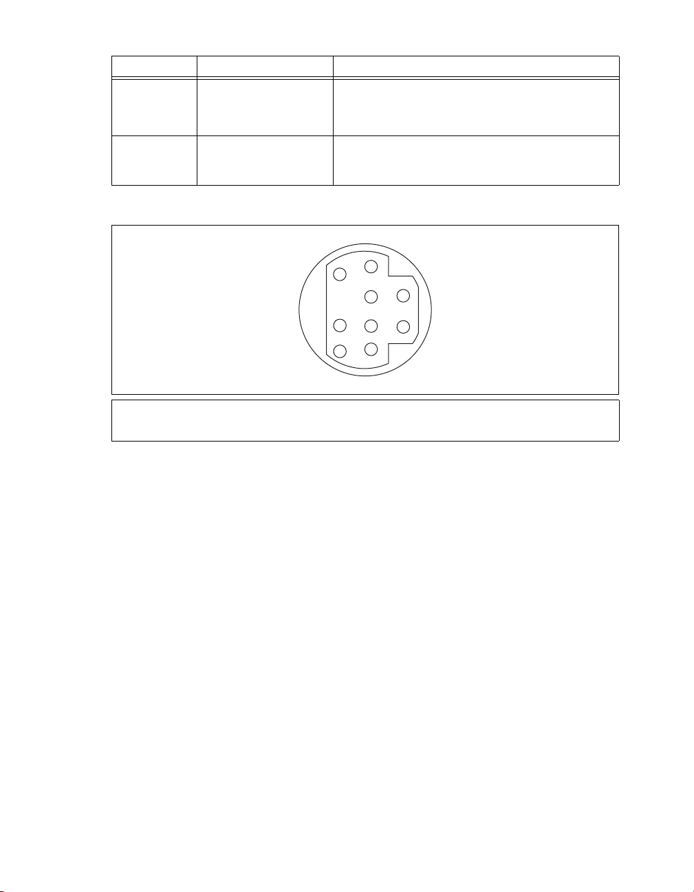
Table 3. NI 5122/5124/5142/5922 Front Panel Signal Connections (Continued)
Connector Description Function
CLK OUT Standard SMB jack
connector
NI 5122/5124/5142: Output for the reference clock or sample
clock.
NI 5922: Output for the reference clock.
AUX I/O 9-pin mini-circular DIN
connector
Provides access to the multipurpose digital timing and
triggering lines, PFI 0, and PFI 1 (with optional cable).
For pinout information, refer to Figure 13.
Figure 13 shows the pin assignments for the 9-pin DIN connector.
3
7
1
4
8
5
2
6
9
1 +5 V (Fused)
2GND
3 Reserved
Figure 13. 9-Pin DIN Connector Pin Assignments for NI 5114/5122/5124/5142/5922
4 Reserved
5 Reserved
6PFI 1
7 Reserved
8 Reserved
9PFI 0
NI High-Speed Digitizers Getting Started Guide 18 ni.com
Page 19
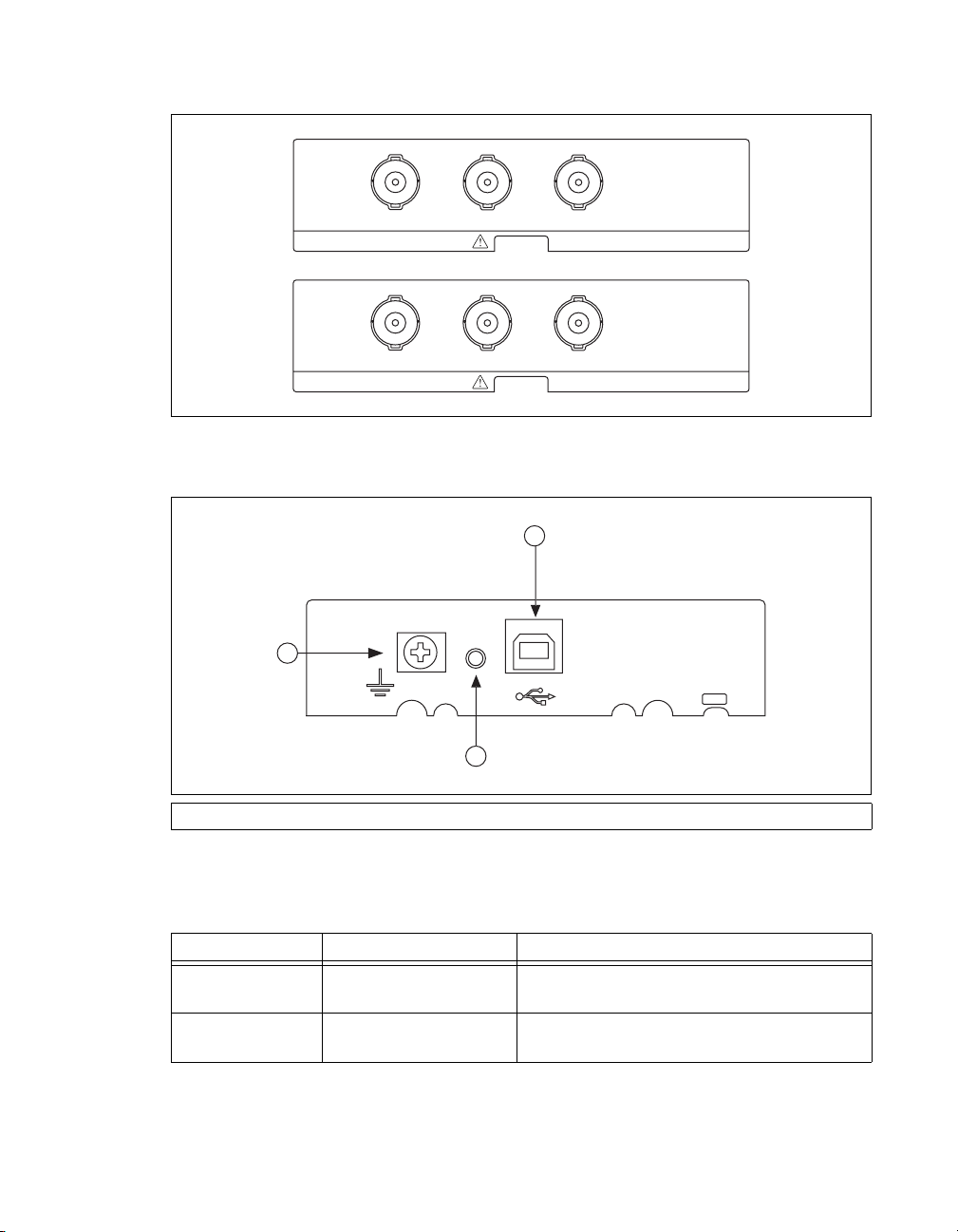
NI 5132/5133 Front Panels
Figure 14 shows the NI USB-5132 and NI USB-5133 front panels.
CH 0
NI USB-5132
CH 0
NI USB-5133
CH 1
CH 1
Figure 14. NI 5132/5133 Front Panels
Figure 15 shows the NI 5132/5133 back panel.
3
PFI 1
8-bit, 50 MS/s Digitizer
PFI 1
8-bit, 100 MS/s Digitizer
1
2
1 Recessed USB port 2LED 3 Ground
Figure 15. NI 5132/5133 Back Panel
Table 4 describes the signal connections for the NI 5132/5133.
Table 4. NI 5132/5133 Front Panel Signal Connections
Connector Description Function
CH 0,
CH 1
Standard BNC connector Analog input connection; digitizes data and triggers
acquisitions.
PFI 1 Standard BNC connector Multipurpose PFI line for sample clock in, digital
trigger in/out, and probe compensation.
© National Instruments Corporation 19 NI High-Speed Digitizers Getting Started Guide
Page 20

NI 5152/5153/5154 Front Panels
Figure 16 shows the NI PXI-5152/5153/5154 and NI PCI-5152/5153/5154 front panels.
ACCESS ACTIVE
CH 0
CH0
TRIG
CH 1
PFI 1PFI 0
TRIG
.
CH1
PFI0
PFI1
Figure 16. NI 5152/5153/5154 Front Panels
Table 5 describes the signal connections for the NI 5152/5153/5154.
Table 5. NI 5152/5153/5154 Front Panel Signal Connections
Connector Description Function
CH 0,
CH 1
TRIG Standard BNC female
PFI 0 Standard SMB jack
PFI 1 Standard SMB jack
Standard BNC female
connector
connector
connector
connector
Analog input connection; digitizes data and triggers
acquisitions.
External analog trigger connection; signals on the
TRIG connector cannot be digitized.
Multipurpose PFI line for reference clock in,
sample clock in, and digital trigger in/out.
Multipurpose PFI line for reference clock out,
probe compensation, and digital trigger in/out.
NI High-Speed Digitizers Getting Started Guide 20 ni.com
Page 21

NI 5622 Front Panels
Figure 17 shows the NI PXIe-5622 front panels.
NI PXIe-5622
16-Bit IF Digitizer
ACCESS ACTIV E
IF IN
PFI 1
CLK IN
CLK OUT
TTL (+5 V MAX)
Figure 17. NI 5622 Front Panel
Table 6 describes the signal connections for the NI 5622.
Table 6. NI 5622 Front Panel Signal Connections
Connector Description Function
IF IN SMA connector Analog input connection; digitizes data and triggers
acquisitions
PFI 1 SMB connector Digital trigger connection (Multipurpose PFI line for
reference clock in, sample clock in, and digital trigger
in/out.)
CLK IN SMA connector Imports an external reference clock or sample clock to
the digitizer
CLK OUT SMA connector Exports the digitizer reference clock or sample clock
© National Instruments Corporation 21 NI High-Speed Digitizers Getting Started Guide
Page 22

Appendix B: Front Panels for Traditional NI-DAQ (Legacy) Devices
This appendix describes digitizer front panels and signal connections for the following Traditional
NI-DAQ (Legacy) devices: NI 5102, NI 5112, NI 5620/5621, and NI 5911.
NI 5102 Front Panels
The NI 5102 is available for PXI and PCI platforms. This section describes the front panels and signal
connections for both types of NI 5102 digitizers.
(NI PXI-5102) Figure 18 shows the NI PXI-5102 front panel. For the AUX connector pinout information,
refer to Figure 19.
NI 5102
PFI 1
AUX
C
H
0
C
H
1
T
R
I
G
Figure 18. NI PXI-5102 Front Panel
NI High-Speed Digitizers Getting Started Guide 22 ni.com
Page 23

Table 7 describes the signal connections for the NI PXI-5102.
Table 7. NI PXI-5102 Front Panel Signal Connections
Connector Description Function
CH 0,
CH 1
TRIG Standard BNC female
PFI 1 Standard SMB jack
Standard BNC female
connector
connector
Analog input connection; digitizes data and triggers
acquisitions.
External analog trigger connection; signals on the TRIG
connector cannot be digitized.
Multipurpose digital timing and triggering signal.
connector
AUX 9-pin mini-circular DIN
connector
Access to PFI 2 (with optional cable). For pinout information,
refer to Figure 19.
Figure 19 shows the pin assignments for the 9-pin DIN connector on the NI PXI-5102.
9
6
8
5
2
1
4
7
3
1 +5 V (Fused)
2GND
3 Reserved
4 Reserved
5 Reserved
6PFI 2
7 Reserved
8 Reserved
9 Reserved
Figure 19. 9-Pin DIN Connector for NI PXI-5102, NI PXI/PCI-5112, and NI PCI-5911
Note The +5 V signal is fused at 1.1 A. However, NI recommends limiting the current from this pin
to 30 mA. The fuse is self-resetting.
© National Instruments Corporation 23 NI High-Speed Digitizers Getting Started Guide
Page 24

(NI PCI-5102) Figure 20 shows the NI PCI-5102 front panel.
CH 0
CH 1
TRIG
PFI 1
PFI 2
Figure 20. NI PCI-5102 Front Panel
Table 8 describes the signal connections for the NI PCI-5102.
Table 8. NI PCI-5102 Front Panel Signal Connections
Connector Description Function
CH 0,
CH 1
TRIG Standard BNC female
PFI 1 Standard SMB jack
Standard BNC female
connector
connector
Analog input connection; digitizes data and triggers
acquisitions.
External analog trigger connection; signals on the TRIG
connector cannot be digitized.
Multipurpose digital timing and triggering signal.
connector
PFI 2 Standard SMB jack
Multipurpose digital timing and triggering signal.
connector
Note When used as inputs, NI 5102 PFI lines can trigger an acquisition and/or allow an external
sample clock connection.
NI High-Speed Digitizers Getting Started Guide 24 ni.com
Page 25

NI 5112 Front Panels
Figure 21 shows the NI PXI-5112 and the NI PCI-5112 front panels. For AUX connector pinout
information, refer to Figure 19.
NATIONAL
INSTRUMENTS
NI PXI-5112
100 MHz
Digital Oscilloscope
PFI 1
C
H
0
PFI 1
AUX
CH 0
C
H
1
T
R
I
G
CH 1
TRIG
Figure 21. NI 5112 Front Panels
Table 9 describes the signal connections on the NI 5112.
Table 9. NI 5112 Front Panel Signal Connections
Connector Description Function
CH 0,
CH 1
TRIG Standard BNC female
PFI 1 Standard SMB jack
Standard BNC female
connector
connector
Analog input connection; digitizes data and triggers
acquisitions.
External analog trigger connection; signals on the TRIG
connector cannot be digitized.
Multipurpose digital timing and triggering signal.
connector
AUX 9-pin mini-circular DIN
connector
Access to PFI 2 (with optional cable). For pinout information,
refer to Figure 19.
© National Instruments Corporation 25 NI High-Speed Digitizers Getting Started Guide
Page 26

NI 5620/5621 Front Panels
Figure 22 shows the NI PXI-5620/5621 front panels.
NI PXI-5620
64 MS/s Digitizer
INPUT
50
+20 dBm MAX
±2 VDC MAX
REF CLK IN
50
+16 dBm MAX
±10 VDC MAX
PFI 1
TTL (+5 V MAX)
NI PXI-5621
64 MS/s Digitizer
INPUT
50
+20 dBm MAX
±3 VDC MAX
REF CLK IN
50
+20 dBm MAX
±10 VDC MAX
PFI 1
TTL (+5 V MAX)
Figure 22. NI 5620/5621 Front Panels
Table 10 describes the signal connections for the NI 5620/5621.
Table 10. NI 5620/5621 Front Panel Signal Connections
Connector Description Function
INPUT Standard SMA female
connector
Analog input connection; digitizes data and triggers
acquisitions.
NI 5620—50 Ω, AC coupled.
NI 5621—50 Ω, DC coupled.
REF CLK IN Standard SMA female
50 Ω, 10 MHz, AC coupled reference clock input.
connector
PFI 1 Standard SMB jack
External digital trigger connection.
connector
NI High-Speed Digitizers Getting Started Guide 26 ni.com
Page 27

NI 5911 Front Panel
Figure 23 shows the NI PCI-5911 front panel. For PFI 2 (AUX) connector pinout information, refer to
Figure 19.
CH 0
PFI 1
PFI 2
Figure 23. NI 5911 Front Panel
Table 11 describes the signal connections for the NI 5911.
Table 11. NI 5911 Front Panel Signal Connections
Connector Description Function
CH 0 Standard BNC female
connector
PFI 1 Standard SMB jack connector Multipurpose digital timing and triggering signal.
PFI 2 (AUX) 9-pin mini-circular DIN
connector
© National Instruments Corporation 27 NI High-Speed Digitizers Getting Started Guide
Analog input connection; digitizes data and triggers
acquisitions.
Access to PFI 2 (with optional cable). For pinout
information, refer to Figure 19.
Page 28

Appendix C: Accessory Front Panels
This appendix describes the front panel and signal connections for the digitizer accessory.
NI 5900 Front Panel
Figure 24 shows the NI PXI-5900 differential amplifier front panel and the connections to the NI 5922.
NI PXI-5900
CH 0 +
CH 0 -
OUT 0
CH 1 +
CH 1 -
OUT 1
NI PXI-5922
Figure 24. NI 5900 Front Panel
Table 12 describes the signal connections for the NI 5900.
Table 12. NI 5900 Front Panel Signal Connections
Connector Description Function
CH 0+ Standard BNC female connector Differential analog input signal for channel 0
CH 0– Standard BNC female connector Differential analog input signal for channel 0
CH 0 OUT Standard SMB jack connector Single-ended analog output for channel 0;
approximately ((CH0+) – (CH0–)) / 4
CH 1+ Standard BNC female connector Differential analog input signal for channel 1
CH 1– Standard BNC female connector Differential analog input signal for channel 1
CH 1 OUT Standard SMB jack connector Single-ended analog output for channel 0;
approximately ((CH1+) – (CH1–)) / 4
NI High-Speed Digitizers Getting Started Guide 28 ni.com
Page 29

Appendix D: Troubleshooting
Front Panel ACCESS LED on PXI/PXI Express Module is Off when PXI/PXI Express Chassis is On
If the ACCESS LED on the digitizer is not lit after you power on the PXI/PXIe chassis, a problem may
exist with the PXI/PXIe power rails, a hardware device, or the LED.
Note The LEDs may not light until the device has been configured in MAX. Before troubleshooting
this issue, verify that the device appears in MAX.
Complete the following steps to troubleshoot this issue:
1. Power off your PXI chassis.
2. Disconnect any signals from the PXI module front panel.
3. Remove the PXI module and inspect for signs of damage. Do not reinstall a damaged device.
4. Reinstall the PXI module as described in section 5. Installing the Hardware.
5. Power on the PXI chassis.
6. Verify that the device appears in MAX.
7. Reset the device in MAX and perform a self-test. For information about performing device resets
and self-tests in MAX, refer to section 6. Configuring and Testing in MAX.
8. If the ACCESS LED still fails to light, contact NI Technical Support at
Back Panel LED on USB Module is Off when Device is Plugged In
If the LED on the digitizer is not lit after it has been plugged into the USB port, a problem may exist
with the software installation, the hardware device, or the LED.
Note The LEDs may not light until the device has been configured in MAX. Before troubleshooting
this issue, verify that the device appears in MAX.
ni.com/support.
Complete the following steps to troubleshoot this issue:
1. Unplug the USB digitizer.
2. Disconnect any signals from the USB digitizer front panel.
3. Reinstall the USB device as described in section 5. Installing the Hardware.
4. Verify that the device appears in MAX.
5. Reset the device in MAX and perform a self-test. For information about performing device resets
and self-tests in MAX, refer to section 6. Configuring and Testing in MAX.
6. If the back panel LED still fails to light, contact NI Technical Support at
ni.com/support.
Device Does Not Appear in MAX
Complete the following steps if the device does not appear in MAX:
1. In the MAX Configuration pane, click Devices and Interfaces to expand the category.
2. Click Traditional NI-DAQ Devices or NI-DAQmx Devices and press <F5> to refresh the list of
installed devices.
3. If the device is still not listed, power off the system, verify that the device is correctly installed, and
restart.
4. If the device still does not appear under Devices and Interfaces, contact NI Technical Support at
ni.com/support.
© National Instruments Corporation 29 NI High-Speed Digitizers Getting Started Guide
Page 30

Device Failed the Self-Test
The MAX self-test performs a brief test of device resources. If the device does not pass the self-test,
complete the following steps:
1. Restart your system.
2. Launch MAX and perform the self-test again. If the device still fails the self-test, proceed to step 3.
3. Uninstall and reinstall NI-SCOPE.
4. If the device still fails the self-test, contact NI Technical Support at
Thermal Shutdown Error
If you receive an over temperature (or thermal shutdown) error and your device shuts down, complete
the following steps to re-enable your device:
1. Power off the computer or chassis that contains the device.
2. Review the procedure in section 5. Installing the Hardware and make any necessary adjustments
to make sure that your device is effectively cooled.
3. Power on the computer or chassis.
Note The thermal shutdown error is reported until the device has cooled to an acceptable operating
temperature and has been successfully reset.
Performance Issues Using MXI Connections
If you are using a MXI interface to control a PXI chassis and you encounter performance or initialization
issues, refer to the MXI documentation to verify that the MXI interface is properly set up. Software
optimization might be necessary.
• (MXI-3) For optimization, select Start»All Programs»National Instruments MXI-3»MXI-3
Optimization. Using a MXI-3 connection without running this application may result in an error
message such as the following:
– maximum amount of time exceeded
–
internal software error
If the software optimization application is not installed on your system, use the MXI software CD
or the National Instruments Driver CD included with your kit to install the software. After
installation, you may need to restart your computer before running the MXI Optimization
Application.
• (MXI-4 and MXI-Express) Optimization is performed automatically by the hardware.
ni.com/support.
If you continue to have initialization or performance issues, refer to the MXI documentation at Start»
All Programs»National Instruments MXI, or visit NI Technical Support at
ni.com/support.
Setting Up SMC-Based Devices for Synchronization
Note The following step is required for any type of synchronization involving an SMC-based
device, including NI-TClk synchronization. For information about NI-TClk synchronization, refer to
NI High-Speed Digitizers Help»Programming»Reference»NI-TClk Synchronization Help.
If you plan to share triggers and/or clocks for the purpose of synchronizing SMC-based devices
(NI 5105/5114/5122/5124/5142/5152/5153/5154/5622/5922), you must identify or configure certain
components in MAX.
NI High-Speed Digitizers Getting Started Guide 30 ni.com
Page 31

(PXI and PXIe Modules) You must identify the PXI/PXIe system controller by completing the following
steps:
1. In the MAX configuration tree,
a. Right-click PXI System»Identify As.
b. Select your controller from the list. For example, select External PC if you are using a MXI
controller in an external PC.
2. Expand the PXI System tree and right-click the name of the chassis you are using.
(PCI Devices) You must configure the RTSI cable by completing the following steps:
1. Connect a RTSI cable between the PCI devices to physically share triggers and/or clocks.
2. In the MAX configuration tree,
a. Right-click NI-DAQmx Devices.
b. Select Create New NI-DAQmx Device»RTSI Cable.
c. Right-click the RTSI cable, then select the device to add to the RTSI cable.
NI 5112 Programming Practices
NI 5112 digitizers contain electromechanical relays that may require special programming practices to
prevent excessive wear. For more information, refer to the NI High-Speed Digitizers Help»Devices»
NI 5112 Overview»Electromechanical Relays.
Appendix E: Where to Go for Support
The National Instruments Web site is your complete resource for technical support. At ni.com/
support
resources to email and phone assistance from NI Application Engineers.
you have access to everything from troubleshooting and application development self-help
A Declaration of Conformity (DoC) is our claim of compliance with the Council of the European
Communities using the manufacturer’s declaration of conformity. This system affords the user
protection for electronic compatibility (EMC) and product safety. You can obtain the DoC for your
product by visiting
calibration certificate for your product at
ni.com/certification. If your product supports calibration, you can obtain the
ni.com/calibration.
National Instruments corporate headquarters is located at 11500 North Mopac Expressway, Austin,
Texas, 78759-3504. National Instruments also has offices located around the world to help address
your support needs. For telephone support in the United States, create your service request at
ni.com/support and follow the calling instructions or dial 512 795 8248. For telephone support
outside the United States, contact your local branch office:
Australia 1800 300 800, Austria 43 662 457990-0, Belgium 32 (0) 2 757 0020,
Brazil 55 11 3262 3599, Canada 800 433 3488, China 86 21 5050 9800,
Czech Republic 420 224 235 774, Denmark 45 45 76 26 00, Finland 358 (0) 9 725 72511,
France 01 57 66 24 24, Germany 49 89 7413130, India 91 80 41190000, Israel 972 3 6393737,
Italy 39 02 41309277, Japan 0120-527196, Korea 82 02 3451 3400, Lebanon 961 (0) 1 33 28 28,
Malaysia 1800 887710, Mexico 01 800 010 0793, Netherlands 31 (0) 348 433 466,
New Zealand 0800 553 322, Norway 47 (0) 66 90 76 60, Poland 48 22 328 90 10,
Portugal 351 210 311 210, Russia 7 495 783 6851, Singapore 1800 226 5886,
Slovenia 386 3 425 42 00, South Africa 27 0 11 805 8197, Spain 34 91 640 0085,
Sweden 46 (0) 8 587 895 00, Switzerland 41 56 2005151, Taiwan 886 02 2377 2222,
Thailand 662 278 6777, Turkey 90 212 279 3031, United Kingdom 44 (0) 1635 523545
© National Instruments Corporation 31 NI High-Speed Digitizers Getting Started Guide
Page 32

National Instruments, NI, ni.com, and LabVIEW are trademarks of National Instruments Corporation. Refer to the Terms of Use section on
ni.com/legal for more information about National Instruments trademarks. Other product and company names mentioned herein are
trademarks or trade names of their respective companies. For patents covering National Instruments products/technology, refer to the appropriate
location: Help»Patents in your software, the patents.txt file on your media, or the National Instruments Patent Notice at ni.com/patents.
© 2003–2009 National Instruments Corporation. All rights reserved.
Page 33

スタートアップガイド
高速デジタイザ
NI
このドキュメントでは、NI高速デジタイザおよびアクセサリの取り付け、構成、テスト、
また
NI-SCOPE
す。 このドキュメントは、
NI 5132、NI 5133、NI 5142、NI 5152、NI 5153、NI 5154、NI 5620、NI 5621、NI 5622
NI 5900、NI 5911
機能の詳細やプログラミング方法については、『NI高速デジタイザヘルプ』を参照してくだ
さい。 デバイス仕様の詳細については、デバイスに付属する仕様書を参照してください。 両
ドキュメントはスタート→すべてのプログラム→
ドキュメントから入手できます。
計測器ドライバソフトウェアによるプログラミング方法について説明しま
、および
NI 5102、NI 5105、NI 5112、NI 5114、NI 5122、NI 5124
NI 5922
に適用します。
National Instruments→NI-SCOPE
、
、
→
目次
最新のドキュメントは、
ni.com/idnet
は、
表記規則
1.
2.
3.
4.
5.
.............................................................................................................................................................2
システム要件を確認する
デバイスをパッケージから取り出す
キットの内容を確認する
その他必要となるもの
ソフトウェアをインストールする
ハードウェアを取り付ける
モジュール
PXI
PXI Express
デバイス
PCI
デバイス
USB
ケーブルストレインリリーフ
USB
USB-513x
Windows
6. MAX
デバイスをプログラミングする
7.
対話式にデータを集録する
プログラムでデータを集録する
NI-SCOPE
測定を行う
8.
付録
A: SMC
NI 5105
NI 5114
を取り付ける
デスクトップでの使用
レールマウント
DIN
パネルに取り付ける
のデバイス認識
での構成とテスト
サンプル
サンプルファインダ
NI
...................................................................................................................................................15
対応デバイスおよび
のフロントパネル
のフロントパネル
ni.com/manuals
で入手できます。
.........................................................................................................................3
.........................................................................................................................3
.........................................................................................................................4
.....................................................................................................................5
........................................................................................................................................5
モジュール
......................................................................................................................6
...........................................................................................................................................6
...........................................................................................................................................8
.......................................................................................................................10
.................................................................................................................10
.....................................................................................................................10
.....................................................................................................................11
.................................................................................................................12
...........................................................................................................................12
.................................................................................................................14
..............................................................................................................................15
.................................................................................................................16
.................................................................................................................17
NI 5122/5124/5142/5922
NI 5132/5133
フロントパネル
で入手できます。
NI-SCOPE
の最新バージョン
...................................................................................................3
.......................................................................................................4
..........................................................................................9
............................................................................................................14
........................................................................................................15
...............................................................................................................15
デバイスのフロントパネル
USB
フロントパネル
.................................................................................18
.............................................16
.........................................................................................................20
2009年3
371133M
月
Page 34

NI 5152/5153/5154
のフロントパネル
従来型
NI-DAQ
のフロントパネル
のフロントパネル
付録
NI 5622
B:
NI 5102
NI 5112
NI 5620/5621
フロントパネル
アクセサリのフロントパネル
フロントパネル
トラブルシューティング
付録
付録
NI 5911
C:
NI 5900
D:
PXI/PXI Express
モジュールのフロントパネル
モジュールが接続されていても
USB
が点灯しない
デバイスが
デバイスがセルフテストで不合格になる
過熱遮断エラー
MXI
同期を行うための
NI 5112
付録
サポート情報
E:
MAX
接続時におけるパフォーマンスの問題
のプログラミング手法
フロントパネル
.............................................................................................21
.................................................................................................................22
(レガシー)用デバイスのフロントパネル
............................................23
.................................................................................................................23
.................................................................................................................26
フロントパネル
.........................................................................................................27
.....................................................................................................................28
....................................................................................................29
.....................................................................................................................29
..............................................................................................................30
シャーシの電源を入れても
ACCESS LED
USB
PXI/PXI Express
が点灯しない
モジュールのバックパネル
................................................30
LED
.......................................................................................................................................30
で表示されない
...................................................................................................31
.....................................................................................31
......................................................................................................................................31
.................................................................................31
対応デバイスの設定
SMC
.............................................................................32
........................................................................................................32
.....................................................................................................................................33
表記規則
このドキュメントでは以下の表記規則を使用します。
→ 矢印(→)は、ネストされたメニュー項目やダイアログボックスのオプションを順
に選択する操作を示します。 たとえば、ファイル→ページ設定→オプションとなっ
ている場合は、ファイルメニューをプルダウンして、ページ設定項目を選択し、最
後のダイアログボックスからオプションを選択します。
このアイコンは、ユーザへのアドバイスを示します。
このアイコンは、注意すべき重要な情報を示します。
このアイコンは、人体への損傷やデータ損失、システムクラッシュなどを回避する
ために必要な注意事項を示します。
太字 太字のテキストは、メニュー項目やダイアログボックスオプションなど、ソフト
ウェアでユーザが選択またはクリックする必要がある項目を示します。
斜体
monospace
monospace
太字 応答を示します。
monospace
斜体
高速デジタイザ スタートアップガイド
NI
斜体のテキストは強調または相互参照を意味します。
このフォントのテキストは、キーボードから入力する必要があるテキストや文字、
コードの一部、プログラムサンプル、構文例を表します。 また、ディスクドライ
ブ、パス、ディレクトリ、ファイル名、拡張子なども示します。
このフォントの太字は、コンピュータの画面に自動的に表示されるメッセージや
また、他のサンプルとは異なるコードラインを強調する場合にも
使用します。
ユーザが入力する必要がある語または値のプレースホルダを示します。
2 ni.com/jp
Page 35

プラットフォーム 特定のプラットフォームを表し、そのすぐ後の記述はそのプラットフォームのみに
適用されることを示します。
PXIe PXI Express
システム要件を確認する
1.
高速デジタイザを
NI
テムが必要です。
NI-SCOPEのCD
メモ
NI-SCOPE
ラム→
National Instruments→NI-SCOPE
Readme
デバイスをパッケージから取り出す
2.
高速デジタイザは、静電気放電(
NI
れます。 デジタイザを袋から取り出す前に、袋をシャーシの金属部分に接触させ、静電気を
除去してください。
注意 デジタイザを取り扱う際は、接地ストラップを装着したり接地された金属に触れ
るなど、必ず身体に対して接地対策を行ってください。 また、デジタイザの露出したピン
や回路に触れないように注意してください。
』ファイルを閲覧できます。
NI-SCOPE
最低要件、推奨要件、サポートされている開発環境(
に含まれる『
をインストール済みのコンピュータでは、スタート→すべてのプログ
ドライバと一緒に使用するには、特定の要件を満たすシス
)については、
ADE
NI-SCOPE Readme
)防止のため静電気防止用袋に梱包されて出荷さ
ESD
』を参照してください。
→ドキュメントを選択して『
NI-SCOPE
袋からデジタイザを取り出し、梱包材とゴムのネジカバー(
り除き、デジタイザにゆるんでいる部品や破損箇所がないかを調べます。 デジタイザに破損
がある場合は、ナショナルインスツルメンツまでご連絡ください。
はコンピュータやシャーシに取り付けないでください。
デジタイザは、使用していない時は静電気防止用袋に入れて保管してください。
キットの内容を確認する
3.
高速デジタイザのキットには、以下が含まれます。
NI
❑ ご注文された
❑
(
NI-SCOPE
DVD
ドライバソフトウェアCDを含む、
サイズ)
❑ その他、付属するアイテム
デバイス仕様書
–
はじめにお読みください: 安全対策と電磁両立性について
–
–『NI
–
–NI
–USB
高速デジタイザスタートアップガイド』(本書)
『強制空冷の維持について』(
スペクトル計測ツールキットCD(メモリオプションが
デバイスのみ)
ケーブル(
– NI LabVIEW SignalExpress CD(USB
高速デジタイザまたはアクセサリ
NI
対応デバイスのみ)
SMC
デバイスのみ)
USB
PXI/PXIe
NI-SCOPE
デバイスのみ)
デバイスのみ)を取
破損しているデジタイザ
計測器ドライバのケース
以上の
8 MB
SMC
対応
© National Instruments Corporation 3 NI
高速デジタイザ スタートアップガイド
Page 36

メモ
対応デバイスは、ナショナルインスツルメンツ
SMC
and Memory Core
NI 5105、NI 5114、NI 5122、NI 5124、NI 5142、NI 5152、NI 5153、NI 5154、NI 5622
および
NI 5922
てください。
その他必要となるもの
キットに含まれるアイテム以外に、以下が必要となります。
SMC(Synchronization
)アーキテクチャに基づいています。
が含まれます。詳細については、『NI高速デジタイザヘルプ』を参照し
対応デバイスには、
SMC
、
❑
マイナスドライバー
1/8 in.
❑ 以下のうちいずれか
(
–
デバイス)
PXI
PXI/CompactPCI
(
PXI Express
–
キュメント
(
–
–
メモ
デバイスを接続する必要があります。 詳細については、
グラミング→リファレンス→
ソフトウェアをインストールする
4.
注意 ハードウェアは、必ずソフトウェアをインストールした後に取り付けてください。
ソフトウェアをインストールするには、以下の手順に従ってください。
(オプション)
1.
ション開発環境(
は、必ず
2. CD
れるウィンドウからソフトウェアをインストールをクリックしてください。
メモ インストールウィンドウが自動的に起動しない場合は、
setup.exe
インストール画面の指示に従います。
3.
(
Windows Vista
画面の指示に従って、インストールを完了します。
インストールが完了すると、再起動、シャットダウン、または後で再起動するかどうか
4.
のダイアログボックスが表示されます。 再起動を選択します。
デバイス)
USB
(
デバイス)
PCI
デバイスで
PCI
LabVIEW
NI-SCOPE
ドライブに
をダブルクリックします。
5. LabVIEW Real-Time
シャーシ、
PXI
シャーシ、コントローラおよびシャーシのドキュメント
デバイス)
デスクトップまたはノートブックPCおよびドキュメント
デスクトップコンピュータおよびドキュメント
NI-TClk
やサードパーティから提供されているツールなどのアプリケー
)を使用する場合、初めに開発環境をインストールします。
ADE
計測器ドライバより先にインストールしてください。
NI-SCOPE CD
)アクセス
モジュールを実行するシステムを使用する場合は、
Measurement & Automation Explorer (MAX)
ンロードします。 詳細については、
ムを選択して、『
リモートシステムヘルプ』を参照してください。
MAX
PXI/SCXI
PXI Express
による同期を行う場合は、
NI-TClk
同期ヘルプを参照してください。
を挿入して、
コンビネーションシャーシ、または
シャーシ、コントローラおよびシャーシのド
ケーブルを使用して
RTSI
高速デジタイザヘルプ→プロ
NI
NI-SCOPE
をインストールします。 表示さ
ドライブを開いて
CD
セキュリティメッセージが表示される場合があります。
/
にて
NI-SCOPE
でヘルプ→ヘルプトピック→リモートシステ
MAX
をターゲットにダウ
PCI
ADE
高速デジタイザ スタートアップガイド
NI
4 ni.com/jp
Page 37

ハードウェアを取り付ける
5.
このセクションでは、
り付ける方法について説明します。
メモ ハードウェアを取り付ける前に、必ずソフトウェアをインストールしてください。
や汚れによる破損を避けるために、デバイスを取り扱う際には、デバイスの端や金属
ESD
ブラケット部分以外には触れないでください。
安全対策と電磁両立性について』を参照してください。
デバイスを使用する場合を除き、ハードウェアを取り付ける前に必ずコン
USB
モジュールは精密機器であるため、取り扱いには注意が必要です。 このモジュール
モジュール
PXI
注意
ピュータやシャーシの電源を切ってください。
NI PXI
を、使用温度範囲または使用湿度範囲を超える環境に配置しないでください。 また、エアダ
スターを使用して、モジュールに付着するほこりを取り除いてください。
液体は使用しないでください。
PXI/PXIe、PCI
、および
プラットフォームのハードウェアを取
USB
詳細については、『はじめにお読みください
手入れ時に溶媒や
:
モジュールは、グリフ(円で囲まれたスロット番号)の記載がある任意の
PXI
に取り付けることができます。
モジュールを取り付けるには、以下の手順に従ってください。
PXI
1. PXI
2. PXI
3. PXI
4.
5.
6.
7.
8. PXI
9.
10. PXI
モジュールを取り付ける前に、
シャーシにファンの速度設定が複数ある場合には、
シャーシを配置する際は、吸排気口が遮蔽されないよう注意します。 詳細について
は、各シャーシのドキュメントを参照してください。
着脱用ハンドルがラッチされていない状態(下向き)になっていることを確認します。
モジュールの脱着ハンドル部分を持ち、図1のようにモジュールを空いているスロッ
トに差し込みます。 モジュールの底部がシャーシのガイドに固定されていることを確認
します。
モジュールを完全にシャーシに押し込み、脱着ハンドルを引き上げて固定します。
モジュールのフロントパネルの上下を取り付けネジで固定します。 両方のネジが適切に
締められていないと、パフォーマンスに影響が出る恐れがあります。
確認します。
モジュールを動作する前に、
(
い。
シャーシファンが動作し、通気を妨げるようなほこりや汚れがついていないことを
PXI
ni.com/jp
シャーシの電源ケーブルのプラグを差し込み、電源を入れます。
で購入可能)を使用して、すべての空の
シャーシの電源を切り、プラグを抜きます。
PXI
に設定します。
HIGH
フィラーパネルまたはスロットブロッカー
スロットに取り付けてくださ
PXI
PXI
スロット
© National Instruments Corporation 5 NI
高速デジタイザ スタートアップガイド
Page 38

1
1PXI
脱着ハンドル(下向きになっていること)
2
PXI Express
「
モジュール」セクションの取り付け手順に従って、モジュールをシャーシの
PXI
PXI Express
シャーシのドキュメントを参照してください。
シャーシ
モジュール
スロットに取り付けます。
3
図
1 PXI
4
3
4
2
モジュールの取り付け
PXI Express
1
NI PXI-1042
ネジ
3
4NI PXI
モジュール
スロットを示す表記については、
NI PXIe-1062Q
1PXI Express
脱着ハンドル
2
デバイス
PCI
デバイスを取り付けるには、以下の手順に従ってください。
PCI
コンピュータの電源を切り、電源プラグを抜きます。
1.
2. PC
高速デジタイザ スタートアップガイド
NI
シャーシ
のカバーを外します。
ネジ
3
4 NI PXI Express
図
2 PXI Express
5
2
シャーシスロットマーク
モジュール
5
モジュールの取り付け
6 ni.com/jp
Page 39

図3に示されているように、空いている
3.
スロットにデバイスを差し込みます。
PCI
3
1
2
1NI PCI
デバイス
ヒント 通気の確保やデバイスの寿命に影響を与えないために、隣接している
ロットは空けてください。
(
NI PCI-5911
ムの中央に位置していることを確認します。
タのカバーに接触している場合、信号の劣化を招く恐れがあります。 ノイズを最小限に
抑えるために、
ださい。
)
NI PCI-5911
コネクタがPCの金属部分に触れることがないように注意してく
BNC
を取り付ける際、
2PCI
図
3 PCI
スロット
の取り付け
コネクタが図4のように金属フレー
BNC
コネクタの外部シェルがコンピュー
BNC
3PC
PCI
ス
図
4 NI PCI-5911
複数の
NI 5911
動作温度を上回り、データの精度が低下する場合があります。
NI 5911
けるか、ファンを追加してください。
デバイスを
4.
© National Instruments Corporation 7 NI
デバイスを同一のコンピュータに取り付けると、仕様に記載されている
デバイスを使用する場合には、1つの
シャーシにネジで固定します。
PCI
の取り付け
スロットを空けてデバイスを取り付
PCI
そのため、複数の
高速デジタイザ スタートアップガイド
Page 40

注意 デバイスのフロントパネルは必ず
は、機械的な安定性と確実な接地接続を確保するために重要です。 デバイスを適切に固定
しないと、デバイスの確度に影響する場合があります。
スロットにネジで固定してください。これ
PCI
USB
(
5. PC
6.
(
7.
メモ
狭い周波数範囲全体に渡るよう、クロック信号を分散します。 拡散スペクトルクロックを
無効にすると、デバイスの確度に影響が出る可能性があります。
対応デバイス)
SMC
プラスチックのレバーを使用するものもあります。このような場合、レバーは使用せず
に、取り外す必要があります。 キットに含まれているネジを使用してデジタイザを固定
してください。 ネジで固定することができない場合は、別のコンピュータシャーシを使
用する必要があります。
のカバーを元どおりに取り付けます。
コンピュータの電源プラグを差し込み、電源を投入します。
対応デバイス)
SMC
します。
確認する方法については、PCのドキュメントを参照してください。
対応デバイスでは、拡散スペクトルクロックは、タイミングクロック信号が
SMC
コンピュータの種類によっては、
拡散スペクトルクロックがPCの
デバイスを固定するために
PCI
で有効になっているか確認
BIOS
デバイス
デバイスを取り付けるには、図5のように
USB
続します。
1
ケーブルをPCおよびデジタイザに接
USB
ノートブック
1
高速デジタイザ スタートアップガイド
NI
PC 2NI USB
2
3
高速デジタイザ
図
5 USB
の取り付け
8 ni.com/jp
3USB
ケーブル
Page 41

ケーブルストレインリリーフ
USB
ケーブルには、以下の2つのストレインリリーフオプションがあります。
USB
固定溝を使用
•
込みます。
ケーブルタイを使用: 図6のように、
•
図6
バーにケーブルタイを通し、
ケーブルを、
: USB
のように、
デバイスの下側にある2つの溝のいずれかに押し
USB
ケーブルのサイズに一致する溝を使用します。
USB
デバイスの下側にあるケーブルタイ取り付け
USB
ケーブルを固定します。
USB
5
5
4
6
3
1
固定溝を使用
1
ケーブルタイを使用
2
ケーブルストレインリリーフ用溝(大)
3USB
ケーブルストレインリリーフ用溝(小)
4USB
図
6 USB
or
2
ケーブル
5USB
ケーブルタイ
6
ケーブルタイ取り付けバー
7
ケーブルストレインリリーフオプション
7
© National Instruments Corporation 9 NI
高速デジタイザ スタートアップガイド
Page 42

USB-513x
USB-513x
できます。
デスクトップでの使用
USB-513x
チックガイドが下部にあります。
デスクトップで使用する場合にデバイスを安定させるには、図7のように、付属の滑り止
め用の脚をデバイスの下側に貼り付けます。
メモ
重ねる場合は、ゴム脚は使用しないでください。
を取り付ける
をデスクトップで使用、または標準
には、複数の
USB-513x
USB-513x
をパネルに取り付ける場合、または他の
3
レールまたはパネルに取り付けることが
DIN
デバイスを積み重ねて使用することができるようにプラス
USB-513x
デバイスの上に積み
1NI USB
DIN
DIN
は、
高速デジタイザ スタートアップガイド
NI
高速デジタイザ
レールマウント
レールマウントキット(製品番号
USB-513x
メモ 「
レールに取り付ける前に、ストレインリリーフ対策を行います。
製品群を標準
ケーブルストレインリリーフ」セクションの説明どおり、
USB
1
2
プラスチックガイド
2
図
7
ゴム脚を
USB-513x
に取り付ける
: 779689-01、USB-513x
レールに取り付けるためのアクセサリです。
DIN
10 ni.com/jp
2
ゴム脚
3
キットには付属しません)
USB-513x をDIN
Page 43

パネルに取り付ける
USB-513x
てください。
をボードまたはパネルに取り付けるには、図8を参照しながら以下の手順に従っ
図
8 USB-513x
メモ デバイスをパネルに取り付ける場合は、ゴム脚を
さい。
メモ 「
ルに取り付ける前に、ストレインリリーフ対策を行います。
技術サポートデータベースのドキュメント「
1.
Mounting Template
ウンロードして印刷します。
は、
テンプレートを使用して、パネル上下に印を付けます。 印は、
2.
隔です。
3. USB
4. #8
5. USB-513x
6. #8
© National Instruments Corporation 11 NI
ケーブルストレインリリーフ」セクションの説明どおり、
USB
」に添付されているパネル取り付け用テンプレートの
技術サポートデータベースのドキュメントを参照するに
ni.com/infoでrd3233
ケーブルを
またはM4ネジをパネルの下の位置にネジ止めします。
またはM4ネジを
USB-513x
の下にあるネジ穴に合わせて、
USB-513x
のコードを入力します。
のコネクタから外します。
をパネルに取り付ける
USB-4065/5132/5133/6509 Panel
USB-513x
上部のネジ穴に挿入してパネルに固定します。
をネジの上に設置します。
USB-513x
高速デジタイザ スタートアップガイド
に取り付けないでくだ
USB-513x
をパネ
PDF
162 mm(6.375 in.
をダ
)間
Page 44

Windows
ハードウェアの取り付け後に初めてコンピュータを起動すると、
取り付けられたデバイスが認識されます。 一部の
すべてのNIデバイスに対して、「新しいハードウェアの検索」ウィザードが起動します。 デ
フォルトでは、デバイスに最適なドライバを検索する(推奨)が選択されています。
たははいをクリックして、各デバイスのソフトウェアをインストールします。
メモ
デバイスを認識します。
ルを完了します。
のデバイス認識
(
デバイス)
USB
Windows
Windows
NI USB-5132/5133
表示されるダイアログボックスで次へをクリックし、インストー
を初めて取り付けた場合、
システムでは、取り付けられた
によって新しく
Windows
次へま
が新しい
Windows
めのダイアログボックスが表示されます。表示されるオプションは、システムにインストー
ルされているデバイスとソフトウェアによって異なります。
• NI LabVIEW SignalExpress
•
•
•
•
6. MAX
1.
が新しく取り付けられたデバイスを認識すると、以下のオプションを選択するた
を使用してこのデバイスの測定を開始するを選択すると
LabVIEW SignalExpress
このデバイスを対話的に使用するを選択すると
(
)が開きます。
SFP
このデバイスでアプリケーションを開始するを選択すると
デバイスを構成しテストするを選択すると、
ます。
何もしないを選択すると、デバイスの認識状態は維持されますが、アプリケーションは
起動しません。
が開きます。
NI-SCOPE
が開き、デバイスの構成を設定でき
MAX
ソフトフロントパネル
LabVIEW
が開きます。
での構成とテスト
デスクトップ上の
を開きます。
MAX
メモ
て
NI-DAQmx
バイスは、
れらのデバイスが
ます。
でデバイスを構成する際は、
MAX
の下に表示され、
MAX
Measurement & Automation
SMC
NI-DAQmx
では従来型
で構成されると、
MAX
NI-DAQ
(レガシー)デバイスで構成されます。 ただし、こ
NI-SCOPE
デバイスとして認識されます。 レガシーデ
アイコンをダブルクリックして、
対応デバイスおよび
でプログラミングできるようになり
デバイスはすべ
USB
高速デジタイザ スタートアップガイド
NI
12 ni .com/jp
Page 45

図9は、
ている
MAX
NI-DAQmx
のツリー構図を示します。
デバイスおよび従来型の
NI-DAQ
(レガシー)の両方が表示され
図
9 MAX
デバイスとインタフェースを展開して、インストールされているデバイスの一覧を表示
2.
します。
リモートシステムを展開します。 ターゲットのIPアドレスまたは名前を検索し、
デバイスとインタフェースを展開します。
デバイスが表示されていない場合は、
3.
されない場合は、「
てください。
い。
メモ
スもあります。
は、『
4. MAX
イスのプログラミング時に必要となります。
•
LabVIEW Real-Time
ハードウェアを取り付ける」のセクションの手順を再度繰り返し
5.
の使用方法については、
MAX
Windows Vista
ご使用のデジタイザと互換性のあるオペレーティングシステムについて
では、サポートされていない従来型
NI-SCOPE Readme
で割り当てられたデバイス番号またはデバイス名を記録します。この番号はデバ
(従来型
ビューに表示します。
バイスのリソース名は、
デバイス番号)です。
NI-DAQ
(レガシー)デバイス)
LabVIEW Real-Time
(
•
NI-DAQmx
スに追加されます。
リー構図ラベルには
デバイス名)。 アプリケーションを開発する際、
デバイス)
モジュールと共にデジタイザを使用している場合、
』を参照してください。
デバイス番号が値の列に表示されます。 デフォルトでは、デ
DAQ::
従来型
たとえば、デジタイザをインストールした場合、デバイスツ
NI PXIe-5122:
NI-DAQ
モジュールでサポートされていません。
割り当てられたデバイス名は、ツリー構図ラベルのデバイ
のツリー構図
を押して画面を更新します。 それでも表示
<F5>
MAX
デバイスを選択して、プロパティを構成
n(n
は
MAX
の下に表示される
dev1
"
のヘルプファイルを参照してくださ
NI-DAQ
によってデバイスに割り当てられた
などのように表示されます(
"
で割り当てられたデバイス名
MAX
(レガシー)デバイ
NI-SCOPE
デバイスは、
dev1
は
© National Instruments Corporation 13 NI
高速デジタイザ スタートアップガイド
Page 46

がリソース名となります。
イスのみが
メモ 従来型
をそのまま使用するには、割り当てられた
の変更を選択し、アプリケーションで使用していた従来型
イス番号を入力します。 デバイスの命名規則の詳細については、
プ→プログラミング→リファレンスに記載されている「
「
niScope
デバイスのセルフテストを実行してインストールを検証します。
5.
(従来型
•
択し、リソース確認を選択します。
(
NI-DAQmx
•
ダイアログボックスが開き、デバイスのテストの結果が表示されます。
メモ デバイスのセルフテストが不合格になった場合は、「
る」のセクションの手順を再度行ってください。 それでも不合格になる場合は、ナショナ
ルインスツルメンツの技術サポートのウェブサイト(
ください。
デバイスのテストパネルを実行して信号を確認します。
6.
デジタイザに信号を接続し、その信号に対して適切な範囲、入力制限、サンプリン
a.
グレート、サンプルモードなどのデバイスパラメータを選択します。
テストパネルにアクセスします。
b.
(従来型
•
(
•
メモ 両タイプのデバイスは、テストパネルの上級ボタンをクリックすることでトリガ
を有効にできます。
LabVIEW Real-Time
NI-DAQ
初期化」VIを参照してください。
NI-DAQ
(レガシー)のデバイス番号を使用する既存のアプリケーション
(レガシー)デバイス)
)
デバイスを右クリックして、セルフテストを選択します。
NI-DAQ
を実行をクリックします。
)
NI-DAQmx
デバイスを右クリックして、テストパネルを選択します。
NI-DAQmx
(レガシー)デバイス)
デバイスの下に表示される
モジュールによってサポートされます。
NI-DAQmx
デバイス名を右クリックして名前
NI-DAQ
NI
niScope_init
デバイスを右クリックし、プロパティを選
NI-SCOPE
(レガシー)のデバ
高速デジタイザヘル
」関数または
ハードウェアを取り付け
5.
ni.com/support/jp
プロパティウィンドウでテストパネル
)を参照して
デバ
すべての
NI-SCOPE
ネル(
キャリブレーションが実行できるのは、
デジタイザの構成とテストが完了したら
7.
デバイスをプログラミングする
7.
NI-SCOPE SFP
グラミング方法でデータを集録できます。 また、
イザの機能を検証することができます。
デジタイザにはセルフキャリブレーション機能が搭載されています。
NI
と
)を使用する2つの方法でこの機能を実行できます。 ただし、
SFP
を使用してプログラミングする方法と、
ADE
を使用した対話式集録、または
対話式にデータを集録する
NI-SCOPE SFP
NI-SCOPE→SCOPE
関する詳細ヘルプを表示することができます。
高速デジタイザ スタートアップガイド
NI
を起動するには、
ソフトフロントパネル
NI-SCOPE
NI-DAQmx
MAX
NI-SCOPE
スタート→すべてのプログラム→
を選択します。
対応デバイスのみとなります。
を終了します。
計測器ドライバを使用したプロ
NI-SCOPE
のサンプルを実行して、デジタ
NI-SCOPE SFP
14 ni.c om/ jp
ソフトフロントパ
でセルフ
MAX
National Instruments
では、各制御器に
→
Page 47

プログラムでデータを集録する
でデジタイザをプログラミングするには、
ADE
てのプログラム→
『
高速デジタイザヘルプ』の「プログラミング」セクションを参照してください。
NI
National Instruments→NI-SCOPE
NI-SCOPE
→ドキュメントからアクセスし、
を使用します。 スタート→すべ
NI-SCOPE
LabVIEW、LabWindowsTM/CVI
CD
べてのプログラム→
『
NI-SCOPE Readme
NI
LabVIEW 7.1
ンプルを検索したり参照することができます。
されているため、特定のデバイスで使用可能なサンプルや測定関数を検索することができま
す。
LabVIEW
アプリケーションを起動して、ヘルプ→サンプルを検索を選択した後、ハードウェア入力と
出力→モジュール式計測器→
測定を行う
8.
高速デジタイザで計測を行うには、以下の手順に従ってください。
NI
1. ADE
2.
3.
4.
5.
「付録
6.
サンプル
TM
、Cで使用可能な
に含まれています。 サンプルの一覧とインストールする場所については、スタート→す
NI-SCOPE
National Instruments→NI-SCOPE
』を参照してください。
サンプルファインダ
以降および
CVI 7.1
以降のユーザは、NIサンプルファインダを使用して、サ
NI-SCOPE
または
LabWindows/CVI
NI-SCOPE
を起動します。
スタート→すべてのプログラム→
択して、サンプルを開きます。 どのサンプルを実行するか不明な場合は、
Started
リソース名制御器またはパラメータに適切な文字列を入力します。 ここで入力する文字
列は、デジタイザが従来型
なります。 デバイス名の詳細については、以下のリソースを参照してください。
•「6. MAX
• NI
• NI
入力信号を集録する際に、必要に応じてパラメータを調整します。
集録する信号を、デジタイザの入力チャンネルの1つに接続します。 接続方法の詳細に
ついては、「付録
い。
サンプルプログラムを実行します。
サンプルを選択してください。
での構成とテスト」のセクション
高速デジタイザヘルプ→プログラミング→リファレンス→
リファレンス→VI→
高速デジタイザヘルプ→プログラミング→リファレンス→
→
Reference Help
niScope_init
A: SMC
B:
従来型
NI-DAQ
(レガシー)用デバイスのフロントパネル」を参照してくださ
で使用できる
(高速デジタイザ)を参照します。
National Instruments→NI-SCOPE
NI-DAQ
niScope
対応デバイスおよび
、もしくは
初期化
NI-SCOPE
NI-DAQmx
デバイスのフロントパネル」または
USB
のサンプルは
→ドキュメントにある
のサンプルはキーワード別に分類
のサンプルを参照するには、
NI-SCOPE
→サンプルを選
Getting
対応デバイスかによって異
NI-SCOPE LabVIEW
NI-SCOPE Function
© National Instruments Corporation 15 NI
高速デジタイザ スタートアップガイド
Page 48

付録
A: SMC
この付録では、
対応デバイスおよび
対応デバイスおよび
SMC
デバイスのフロントパネル
USB
デバイス
USB
NI 5105、NI 5114、NI 5122
NI 5124、NI 5132、NI 5133、NI 5142、NI 5152、NI 5153、NI 5154、NI 5622
NI 5922
デジタイザのフロントパネルと信号接続について説明します。
、
、および
NI 5105
のフロントパネル
図10は、
NI PXI-5105
および
NI PCI-5105
NI PXI-5105
12-Bit 60 MS/s Digitizer
CH 0
CH 1
CH 2
CH 3
CH 4
CH 5
CH 6
CH 7
PFI 1
のフロントパネルを示します。
NI PCI-5105
CH 0
CH 1
CH 2
CH 3
CH 4
CH 5
CH 6
CH 7
PFI 1
表1は、
NI 5105
コネクタ 説明 機能
の信号接続を示します。
CH 0~CH 7 SMB
PFI 1
高速デジタイザ スタートアップガイド
NI
SMB
図
10 NI 5105
表
1 NI 5105
コネクタ(標準) アナログ入力接続。データのデジタル化とトリガ集録。
コネクタ(標準) デジタルトリガ入出力、外部クロック入力、基準クロッ
フロントパネル
フロントパネルの信号接続
ク入出力、タイムベース出力汎用
PFI
ライン。
16 ni .com/jp
Page 49

NI 5114
のフロントパネル
図11は、
NI PXI-5114
ン配列情報については、図13を参照してください。
および
NI PCI-5114
NI PXI-5114
のフロントパネルを示します。
AUX
コネクタのピ
表2は、
NI 5114
CH 0
CH 1
TRIG
CLK IN
AUX I/O
図
11 NI 5114
の信号接続を示します。
表
2 NI 5114
フロントパネルの信号接続
CH 0
CH 1
TRIG
CLK IN
AUX I/O
NI PCI-5114
フロントパネル
MAX
+5 V
コネクタ 説明 機能
CH 0、CH 1 BNC
TRIG
CLK IN
AUX I/O
メスコネクタ(標準) アナログ入力接続。データのデジタル化とトリガ
集録。
メスコネクタ(標準) 外部アナログトリガ接続。
BNC
コネクタ(標準) 外部基準クロックまたはサンプルクロックのデジ
SMB
ピンミニサーキュラ
9
コネクタ
DIN
れている信号のデジタル化は不可。
タイザへの入力。
汎用デジタルタイミング/トリガライン、
および
ピン配列に関する情報については、図13を参照の
こと。
へのアクセス(別途ケーブルが必要)。
PFI 1
© National Instruments Corporation 17 NI
コネクタに接続さ
TRIG
、
PFI 0
高速デジタイザ スタートアップガイド
Page 50

NI 5122/5124/5142/5922
図12は、
ネルを示します。
NI PXI-5122/5124/5142/5922
NI PXI-5122
フロントパネル
および
および
NI PXIe-5122
NI PCI-5122/5124/5142/5922
のフロントパネルは同じです。
のフロントパ
表3は、
CH 0
NI 5122/5124/5142/5922
表
3 NI 5122/5124/5142/5922
コネクタ 説明 機能
、
BNC
CH 1
TRIG
CLK IN
高速デジタイザ スタートアップガイド
NI
BNC
SMB
図
12 NI 5122/5124/5142/5922
の信号接続を示します。
フロントパネル
フロントパネルの信号接続
メスコネクタ(標準)
メスコネクタ(標準) 外部アナログトリガ接続。
コネクタ(標準)
アナログ入力接続。データのデジタル化とトリガ集録。
ている信号のデジタル化は不可。
NI 5122/5124/5142:
クもしくはサンプルクロック入力。
NI 5922:
18 ni .com/jp
デジタイザへの外部基準クロック入力。
デジタイザへの外部基準クロッ
コネクタに接続され
TRIG
Page 51
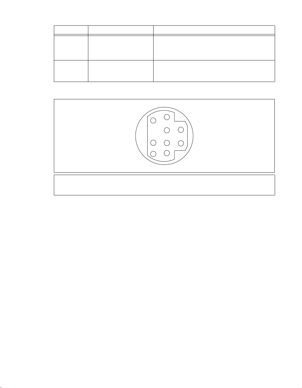
表
3 NI 5122/5124/5142/5922
コネクタ 説明 機能
CLK OUT
AUX I/O
コネクタ(標準)
SMB
ピンミニサーキュラ
9
コネクタ
DIN
フロントパネルの信号接続 (続き)
NI 5122/5124/5142:
ロック出力。
NI 5922:
汎用デジタルタイミング/トリガライン、
よび
配列に関する情報については、図
基準クロック出力。
へのアクセス(別途ケーブルが必要)。 ピン
PFI 1
基準クロックまたはサンプルク
PFI 0
を参照のこと。
13
、お
ピン
9
DIN
1+5 V (
2GND
予約済み
3
コネクタピンの割り当ては、図13のとおりです。
3
7
1
4
8
5
2
6
9
ヒューズ付き
図
13 NI 5114/5122/5124/5142/5922の9
)
予約済み
4
予約済み
5
6PFI 1
ピン
予約済み
7
予約済み
8
9PFI 0
コネクタピンの割り当て
DIN
© National Instruments Corporation 19 NI
高速デジタイザ スタートアップガイド
Page 52

NI 5132/5133
図14は、
フロントパネル
NI USB-5132
および
NI USB-5133
のフロントパネルを示します。
図15は、
CH 0
NI USB-5132
CH 0
NI USB-5133
NI 5132/5133
3
CH 1
CH 1
図
14 NI 513 2 / 5133
PFI 1
PFI 1
フロントパネル
のバックパネルを示します。
1
8-bit, 50 MS/s Digitizer
8-bit, 100 MS/s Digitizer
埋め込み式
1
表4は、
コネクタ 説明 機能
、
CH 0
ポート
USB
NI 5132/5133
標準
CH 1
PFI 1
高速デジタイザ スタートアップガイド
NI
標準
2
2LED
図
15 NI 513 2 / 5133
バックパネル
3
グランド
の信号接続を示します。
表
4 NI 5132/5133
コネクタ アナログ入力接続。データのデジタル化とトリガ集録。
BNC
コネクタ サンプルクロック入力、デジタルトリガ入出力、およびプ
BNC
フロントパネルの信号接続
ローブ補正用の汎用
PFI
ライン。
20 ni.com/jp
Page 53

NI 5152/5153/5154
図16は、
ます。
NI PXI-5152/5153/5154
フロントパネル
および
ACCESS ACTIVE
CH 0
NI PCI-5152/5153/5154
CH0
のフロントパネルを示し
TRIG
CH 1
PFI 1PFI 0
図
16 NI 5152/5153/5154
表5は、
CH 0
NI 5152/5153/5154
表
5 NI 5152/5153/5154
コネクタ 説明 機能
、
メスコネクタ(標準) アナログ入力接続。データのデジタル化とトリガ
BNC
の信号接続を示します。
CH 1
TRIG
PFI 0
PFI 1
メスコネクタ(標準) 外部アナログトリガ接続。
BNC
コネクタ(標準)
SMB
コネクタ(標準)
SMB
TRIG
.
CH1
PFI0
PFI1
フロントパネル
フロントパネルの信号接続
集録。
れている信号のデジタル化は不可。
基準クロック入力、サンプルクロック入力、デジ
タルトリガ入出力用の汎用
基準クロック出力、プローブ補正、デジタルトリ
ガ入出力用の汎用
PFI
TRIG
PFI
ライン。
コネクタに接続さ
ライン。
© National Instruments Corporation 21 NI
高速デジタイザ スタートアップガイド
Page 54

NI 5622
図17は、
のフロントパネル
NI PXIe-5622
のフロントパネルを示します。
NI PXIe-5622
16-Bit IF Digitizer
ACCESS ACT IVE
IF IN
PFI 1
CLK IN
CLK OUT
TTL (+5 V MAX)
表6は、
NI 5622
図
17 NI 5622
の信号接続を示します。
表
6 NI 5622
フロントパネル
フロントパネルの信号接続
コネクタ 説明 機能
IF IN
PFI 1
コネクタ アナログ入力接続、データのデジタル化とトリガ集録
SMA
コネクタ デジタルトリガ接続(基準クロック入力、サンプルクロック入力、
SMB
デジタルトリガ入出力用の汎用
CLK IN
CLK OUT
コネクタ
SMA
コネクタ デジタイザの基準クロックまたはサンプルクロックをエクスポート
SMA
外部基準クロックまたはサンプルクロックをデジタイザにインポート
ライン。)
PFI
高速デジタイザ スタートアップガイド
NI
22 ni.com/jp
Page 55

付録
従来型
B:
NI-DAQ
この付録では、従来型
NI 5911
デジタイザのフロントパネルと信号接続について説明します。
(レガシー)用デバイスのフロントパネル
NI-DAQ
(レガシー)デバイス
NI 5102、NI 5112、NI 5620/5621
、
NI 5102
(
のフロントパネル
NI 5102
両方の
列情報については、図
には、
NI 5102
NI PXI-5102
PXIとPCI
デジタイザのフロントパネルと信号接続について説明します。
)
図18
プラットフォームがあります。 このセクションでは、
は、
NI PXI-5102
を参照してください。
19
のフロントパネルを示します。
NI 5102
PFI 1
AUX
C
H
0
C
H
1
T
R
I
G
コネクタのピン配
AUX
図
18 NI PXI-5102
© National Instruments Corporation 23 NI
フロントパネル
高速デジタイザ スタートアップガイド
Page 56

表7は、
NI PXI-5102
の信号接続を示します。
表
7 NI PXI-5102
コネクタ 説明 機能
CH 0
、
メスコネクタ(標準) アナログ入力接続。データのデジタル化とトリガ
BNC
CH 1
TRIG
PFI 1
AUX
メスコネクタ(標準) 外部アナログトリガ接続。
BNC
コネクタ(標準) 汎用デジタルタイミング/トリガ信号。
SMB
ピンミニサーキュラ
9
コネクタ
フロントパネルの信号接続
集録。
れている信号のデジタル化は不可。
DIN
へのアクセス(別途ケーブルが必要)。 ピン配
PFI 2
列に関する情報については、図
コネクタに接続さ
TRIG
を参照のこと。
19
NI PXI-5102の9
予約済み
メモ
を
30 mA
ヒューズ付き
図
19 NI PXI-5102、NI PXI/PCI-5112、NI PCI-5911の9
+5 V
以内に制限して使用してください。 このヒューズはセルフリセット型です。
1+5 V (
2GND
3
ピン
)
信号には
コネクタピンの割り当ては、図19のとおりです。
DIN
9
6
8
5
2
1
4
7
3
予約済み
4
予約済み
5
6PFI 2
7
8
9
ピン
のヒューズが取り付けられていますが、このピンからの電流
1.1 A
予約済み
予約済み
予約済み
DIN
コネクタ
高速デジタイザ スタートアップガイド
NI
24 ni.com/jp
Page 57

(
NI PCI-5102
)
図20
は、
NI PCI-5102
のフロントパネルを示します。
CH 0
CH 1
TRIG
PFI 1
PFI 2
図
20 NI PCI-5102
表8は、
CH 0
NI PCI-5102
コネクタ 説明 機能
、
の信号接続を示します。
表
8 NI PCI-5102
メスコネクタ(標準) アナログ入力接続。データのデジタル化とトリガ
BNC
CH 1
TRIG
PFI 1
PFI 2
メモ
NI 5102 PFI
メスコネクタ(標準) 外部アナログトリガ接続。
BNC
コネクタ(標準) 汎用デジタルタイミング/トリガ信号。
SMB
コネクタ(標準) 汎用デジタルタイミング/トリガ信号。
SMB
ラインを入力として使用する場合には、集録のトリガや外部サンプル
フロントパネル
フロントパネルの信号接続
集録。
されている信号のデジタル化は不可。
クロック接続が可能となります。
© National Instruments Corporation 25 NI
コネクタに接続
TRIG
高速デジタイザ スタートアップガイド
Page 58

NI 5112
のフロントパネル
図21は、
NI PXI-5112
ン配列情報については、図19を参照してください。
および
NI PCI-5112
NATIONAL
INSTRUMENTS
NI PXI-5112
100 MHz
Digital Oscilloscope
PFI 1
C
H
0
のフロントパネルを示します。
AUX
PFI 1
CH 0
AUX
コネクタのピ
CH 1
TRIG
表9は、
NI 5112
C
H
1
T
R
I
G
図
21 NI 5112
の信号接続を示します。
フロントパネル
表
9 NI 5112
コネクタ 説明 機能
CH 0
、
メスコネクタ(標準) アナログ入力接続。データのデジタル化とトリガ
BNC
CH 1
TRIG
PFI 1
AUX
メスコネクタ(標準) 外部アナログトリガ接続。
BNC
コネクタ(標準) 汎用デジタルタイミング/トリガ信号。
SMB
ピンミニサーキュラ
9
コネクタ
フロントパネルの信号接続
集録。
されている信号のデジタル化は不可。
DIN
へのアクセス(別途ケーブルが必要)。 ピン配
PFI 2
列に関する情報については、図
コネクタに接続
TRIG
を参照のこと。
19
高速デジタイザ スタートアップガイド
NI
26 ni.com/jp
Page 59

NI 5620/5621
図22は、
フロントパネル
NI PXI-5620/5621
のフロントパネルを示します。
表10は、
NI 5620/5621
表
NI PXI-5620
64 MS/s Digitizer
INPUT
50
+20 dBm MAX
±2 VDC MAX
REF CLK IN
50
+16 dBm MAX
±10 VDC MAX
PFI 1
TTL (+5 V MAX)
図
22 NI 5620/5621
の信号接続を示します。
10 NI 5620/5621
フロントパネルの信号接続
NI PXI-5621
64 MS/s Digitizer
INPUT
50
+20 dBm MAX
±3 VDC MAX
REF CLK IN
50
+20 dBm MAX
±10 VDC MAX
PFI 1
TTL (+5 V MAX)
フロントパネル
コネクタ 説明 機能
INPUT
メスコネクタ(標準)
SMA
アナログ入力接続。データのデジタル化とトリガ集録。
NI 5620: 50Ω、AC
NI 5621: 50Ω、DC
REF CLK IN
PFI 1
メスコネクタ(標準)
SMA
コネクタ(標準) 外部デジタルトリガ接続。
SMB
50 Ω、10 MHz、AC
© National Instruments Corporation 27 NI
カプリング。
カプリング。
カプリング基準クロック入力。
高速デジタイザ スタートアップガイド
Page 60

NI 5911
図23は、
については、図19を参照してください。
フロントパネル
NI PCI-5911
のフロントパネルを示します。
CH 0
PFI 1
PFI 2
PFI 2 (AUX)
コネクタのピン配列情報
表11は、
コネクタ 説明 機能
NI 5911
CH 0
PFI 1
PFI 2 (AUX)
高速デジタイザ スタートアップガイド
NI
の信号接続を示します。
BNC
SMB
ピンミニサーキュラ
9
コネクタ
図
23 NI 5911
表
11 NI 5911
メスコネクタ(標準)
コネクタ(標準) 汎用デジタルタイミング/トリガ信号。
DIN
フロントパネル
フロントパネルの信号接続
アナログ入力接続。データのデジタル化とトリガ集録。
へのアクセス(別途ケーブルが必要)。 ピン配列
PFI 2
に関する情報については、図
28 ni.com/jp
を参照のこと。
19
Page 61

付録
アクセサリのフロントパネル
C:
この付録には、デジタイザアクセサリのフロントパネルおよび信号接続が記載されていま
す。
NI 5900
図24は、
フロントパネル
NI PXI-5900
差動アンプのフロントパネルおよび
NI PXI-5900
CH 0 +
CH 0 -
OUT 0
CH 1 +
CH 1 -
OUT 1
NI PXI-5922
NI 5922
との接続を示します。
図
24 NI 5900
表12は、
コネクタ 説明 機能
NI 5900
CH 0+
CH 0–
CH 0 OUT
CH 1+
CH 1–
CH 1 OUT
© National Instruments Corporation 29 NI
の信号接続を示します。
表
12 NI 5900
メスコネクタ(標準) チャンネル0用差動アナログ入力信号
BNC
メスコネクタ(標準) チャンネル0用差動アナログ入力信号
BNC
コネクタ(標準) チャンネル0用シングルエンドアナログ出力。
SMB
メスコネクタ(標準) チャンネル1用差動アナログ入力信号
BNC
メスコネクタ(標準) チャンネル1用差動アナログ入力信号
BNC
コネクタ(標準) チャンネル0用シングルエンドアナログ出力。
SMB
フロントパネル
フロントパネルの信号接続
およそ
((CH0+) – (CH0–)) / 4
およそ
((CH1+) – (CH1–)) / 4
高速デジタイザ スタートアップガイド
Page 62

付録
トラブルシューティング
D:
PXI/PXI Express
ロントパネル
PXI/PXIe
PXI/PXIe
ります。
この問題のトラブルシューティングは、以下の手順で行ってください。
1. PXI
2. PXI
3. PXI
4.
5. PXI
6.
7. M AX
8.
ACCESS LED
シャーシの電源を投入してもデジタイザの
の電源レール、ハードウェアデバイス、
メモ
LEDは、MAX
この問題のトラブルシューティングを開始する前に、
か確認してください。
シャーシの電源を切ります。
モジュールのフロントパネルへの信号接続をすべて取り外します。
モジュールをシャーシから取り外し、破損がないか確認します。 破損しているデバ
イスは再度取り付けないでください。
「
ハードウェアを取り付ける」セクションの説明に従って、
5.
り付けます。
シャーシの電源を投入します。
デバイスが
でデバイスをリセットし、セルフテストを実行します。
ト、セルフテストする方法については、「
照してください。
上記の手順を行っても
ツの技術サポート(
シャーシの電源を入れても
が点灯しない
でのデバイスの構成が完了しないと点灯しないことがあります。
で表示されることを確認します。
MAX
ACCESS LED
ni.com/jp/support
が点灯しない場合は、ナショナルインスツルメン
PXI/PXI Express
ACCESS LED
のいずれかに問題がある可能性があ
LED
でこのデバイスが表示される
MAX
6. MAX
)にお問い合わせください。
での構成とテスト」セクションを参
モジュールのフ
が点灯しない場合は、
モジュールを再度取
PXI
でデバイスをリセッ
MAX
モジュールが接続されていても
USB
しない
ポートに接続してもデジタイザの
USB
トール、ハードウェアデバイス、
メモ
LEDは、MAX
この問題のトラブルシューティングを開始する前に、
か確認してください。
この問題のトラブルシューティングは、以下の手順で行ってください。
1. USB
2. USB
3.「5.
4.
5. MAX
6.
高速デジタイザ スタートアップガイド
NI
デジタイザの電源プラグを抜きます。
デジタイザのフロントパネルへの信号接続をすべて取り外します。
ハードウェアを取り付ける」セクションの説明に従って、
付けます。
デバイスが
ト、セルフテストする方法については、「
照してください。
上記の手順を行ってもバックパネルの
ルメンツの技術サポート(
MAX
でデバイスをリセットし、セルフテストを実行します。
モジュールのバックパネル
USB
が点灯しない場合は、ソフトウェアのインス
LED
のいずれかに問題がある可能性があります。
LED
でのデバイスの構成が完了しないと点灯しないことがあります。
でこのデバイスが表示される
MAX
デバイスを再度取り
USB
で表示されることを確認します。
でデバイスをリセッ
MAX
6. MAX
LED
ni.com/jp/support
30 ni.com/jp
での構成とテスト」セクションを参
が点灯しない場合は、ナショナルインスツ
)にお問い合わせください。
LED
が点灯
Page 63

デバイスが
MAX
1. MAX
2.
3.
4.
MAX
にデバイスが表示されない場合は、以下の手順に従ってください。
従来型
し、インストールされているデバイスの一覧を更新します。
上記の手順を行ってもデバイスが表示されない場合は、システムの電源を切り、デバイ
スが適切に取り付けられているか確認した後、再度電源を投入します。
それでもデバイスとインタフェースの下に表示されない場合は、ナショナルインスツル
メンツの技術サポート(
で表示されない
構成ペーンで、デバイスとインタフェースをクリックして展開します。
NI-DAQ
デバイスまたは
ni.com/jp/support
NI-DAQmx
デバイスがセルフテストで不合格になる
のセルフテストでは、デバイスリソースを確認します。 セルフテストでデバイスが不
MAX
合格になった場合は、以下の手順に従ってください。
コンピュータを再起動します。
1.
2. MAX
3. NI-SCOPE
4.
を起動し、再度セルフテストを実行します。 上記の手順を行ってもデバイスがセ
ルフテストに合格しない場合は、手順3に進んでください。
をアンインストールし、再インストールします。
それでもセルフテストに合格しない場合は、ナショナルインスツルメンツの技術サポー
ni.com/jp/support
ト(
)にお問い合わせください。
過熱遮断エラー
過熱(または過熱遮断)によりエラーが発生し、デバイスが停止した場合は、以下の方法に
従ってデバイスを再度有効にします。
デバイスが取り付けられているコンピュータまたはシャーシの電源を切ります。
1.
2.「5.
3.
ハードウェアを取り付ける」セクションの手順を再度確認し、デバイスを効果的に
冷却するための手順を必要に応じて追加します。
コンピュータまたはシャーシの電源を投入します。
メモ 過熱遮断エラーは、デバイスが適切な動作温度に戻り、また、正常にリセットさ
れるまで発生し続けます。
デバイスをクリックして
)にお問い合わせください。
<F5>
キーを押
接続時におけるパフォーマンスの問題
MXI
インタフェースによる
MXI
る問題が発生する場合は、
定されていることを確認します。また、
(
•
(
•
© National Instruments Corporation 31 NI
)
最適化するには、スタート→すべてのプログラム→
MXI-3
→
MXI-3
MXI-3
–
–
ソフトウェアを最適化するアプリケーションがシステムにインストールされていない場
合は、
CD
終了後に、コンピュータの再起動を必要とする場合があります。
MXI-4
MXI-3 Optimization
を使用すると、以下のようなエラーメッセージが表示されることがあります。
maximum amount of time exceeded
internal software error
ソフトウェアCDまたはキットに付属する
MXI
からインストールしてください。
および
MXI-Express
シャーシの制御時にパフォーマンスの低下や初期化に関す
PXI
のドキュメントを参照して
MXI
ソフトウェアの最適化が必要な場合もあります。
を選択します。 このアプリケーションを実行せずに
(タイムアウトエラー)
(内部ソフトウェアエラー)
MXI Optimization Application
)
最適化は、ハードウェアによって自動的に実行されます。
インタフェースが適切に設
MXI
National Instruments
National Instruments Driver
のインストール
高速デジタイザ スタートアップガイド
Page 64

上記の手順を行っても初期化やパフォーマンスに問題がある場合は、スタート→すべてのプ
ログラム→
ショナルインスツルメンツの技術サポートのウェブサイト(
してください。
National Instruments MXI
を選択して
のドキュメントを参照するか、ナ
MXI
ni.com/jp/support
)を参照
同期を行うための
メモ
SMC
順を行う必要があります。
ログラミング→リファレンス→
デバイス(
SMC
ためにトリガやクロックを共有する場合は、
あります。
(
および
PXI
する必要があります。
1. MAX
のツリー構図で
a. PXI
一覧からコントローラを選択します。 たとえば、PCから
b.
する場合は、「外部PC」を選択します。
2. PXI
(
1. PCI
2. MAX
システムツリーを展開し、使用するシャーシの名前を右クリックします。
デバイス)
PCI
デバイス間を
のツリー構図で
a. NI-DAQmx
新規
b.
c. RTSI
NI 5112
のプログラミング手法
NI 5112
特殊なプログラミング手法を必要とする場合があります。 詳細については、
ザヘルプ→デバイス→
デジタイザはメカニカルリレーを搭載しているため、過度の磨耗を避けるために、
SMC
対応デバイスの設定
対応デバイスで同期(
NI-TClk
NI-TClk
NI-TClk
による同期については、
を含むすべての同期)を行うには、以下の手
NI
同期ヘルプを参照してください。
高速デジタイザヘルプ→プ
NI 5105/5114/5122/5124/5142/5152/5153/5154/5622/5922
にて必要な項目を識別、構成する必要が
MAX
モジュール)
PXIe
以下の手順に従って、
PXI/PXIe
システムコントローラを認識
システム→次のモデルとして識別を右クリックします。
以下の手順に従って
ケーブルで接続して、トリガ/クロックを物理的に共有します。
RTSI
デバイスを右クリックします。
NI-DAQmx
ケーブルを右クリックし、
デバイスを作成→
NI 5112
概要→メカニカルリレーを参照してください。
ケーブルを構成する必要があります。
RTSI
ケーブルを選択します。
RTSI
ケーブルに追加したいデバイスを選択します。
RTSI
)を同期する
コントローラを使用
MXI
高速デジタイ
NI
高速デジタイザ スタートアップガイド
NI
32 ni.com/jp
Page 65

付録
サポート情報
E:
技術サポートリソースの一覧は、ナショナルインスツルメンツのウェブサイトでご覧いただ
けます。
ルフヘルプリソースから、ナショナルインスツルメンツのアプリケーションエンジニアの
メール/電話の連絡先まで、あらゆるリソースを参照することができます。
ni.com/jp/support
では、トラブルシューティングやアプリケーション開発のセ
E
適合宣言(
令への適合の宣言のことです。
製品の安全性に関する情報が提供されます。 ご使用の製品の適合宣言は、
certification
トされている場合、
(英語)を入手してご利用になることもできます。
ナショナルインスツルメンツでは、米国本社(
Texas, 78759-3504
本国内での電話サポートについては、サービスリクエストを
するか、
い。日本国外での電話サポートについては、各国の営業所にご連絡ください。
イスラエル
インド
オーストラリア
オランダ
韓国
スイス
スペイン
タイ
中国
ドイツ
ニュージーランド
フィンランド
ブラジル
ベルギー
ポルトガル
南アフリカ
レバノン
91 80 41190000,
82 02 3451 3400,
41 5 6 2005151,
662 278 6777,
86 21 5050 9800,
49 89 7413130,
)とは、その会社の自己適合宣言を用いた、さまざまな欧州閣僚理事会指
Doc
この制度により、電磁適合性(
(英語)から入手できます。 ご使用の製品でキャリブレーションがサポー
ni.com/calibration
からその製品の
Calibration Certificate
に対するユーザ保護や
EMC)
ni.com/
11500 North Mopac Expressway, Austin,
)および各国の現地オフィスにてお客様にサポート対応しています。 日
ni.com/jp/support
0120-527196
(フリーダイヤル)または
972 3 6393737,
英国
1800 300 800,
31 (0) 348 433 466,
シンガポール
スウェーデン
34 91 640 0085,
台湾
886 02 2377 2222,
デンマーク
トルコ
0800 553 322,
358 (0) 9 725 72511,
55 11 3262 3599,
32 (0) 2 757 0020,
351210311210,
27 0 11 805 8197,
961(0)1332828,
イタリア
39 02 41309277,
44 (0) 1635 523545,
オーストリア
カナダ
800 433 3488,
1800 226 5886,
46 (0) 8 587 895 00,
スロベニア
386 3 425 42 00,
45 45 76 26 00,
90 212 279 3031,
ノルウェー
フランス
米国
512 683 0100,
ポーランド
マレーシア
メキシコ
ロシア
48 22 328 90 10,
1800 887710,
01 800 010 0793,
7 495 783 6851
03-5472-2970
43 662 457990-0,
チェコ
420 224 235 774,
47 (0) 66 90 76 60,
01 57 66 24 24,
(大代表)にお電話くださ
で作成
© National Instruments Corporation 33 NI
高速デジタイザ スタートアップガイド
Page 66

Page 67

Page 68

National Instruments、NI、ni.com
National Instruments
び企業名は、それぞれの企業の商標または商号です。
ヘルプ→特許情報)、メディアに含まれている
(
リソースから参照してください。
の商標の詳細については、
、および
LabVIEWはNational Instruments Corporation
ni.com/legal
patents.txt
の「
National Instruments
Terms of Use
ファイル、または「
」セクションを参照してください。本文書中に記載されたその他の製品名およ
の製品/技術を保護する特許については、ソフトウェアで参照できる特許情報
National Instruments Patent Notice
(米国ナショナルインスツルメンツ社)の商標です。
© 2003–2009 National Instruments Corporation. All rights reserved.Printed in <Country>.
ni.com/patents
」(
)のうち、該当する
37xxxxX-0112 2009年XX
月
 Loading...