

Page 1

™
NI-488.2
NI-488.2 User Manual for Windows
NI-488.2 User Manual for Windows
June 1999 Edition
Part Number 321819D-01
Page 2

Worldwide Technical Support and Product Information
www.natinst.com
National Instruments Corporate Headquarters
11500 North Mopac Expressway Austin, Texas 78759-3504 USA Tel: 512 794 0100
Worldwide Offices
Australia 03 9879 5166, Austria 0662 45 79 90 0, Belgium 02 757 00 20, Brazil 011 284 5011,
Canada (Ontario) 905 785 0085, Canada (Québec) 514 694 8521, China 0755 3904939, Denmark 45 76 26 00,
Finland 09 725 725 11, France 01 48 14 24 24, Germany 089 741 31 30, Hong Kong 2645 3186,
India 91805275406, Israel 03 6120092, Italy 02 413091, Japan 03 5472 2970, Korea 02 596 7456,
Mexico (D.F.) 5 280 7625, Mexico (Monterrey) 8 357 7695, Netherlands 0348 433466, Norway 32 27 73 00,
Singapore 2265886, Spain (Madrid) 91 640 0085, Spain (Barcelona) 93 582 0251, Sweden 08 587 895 00,
Switzerland 056 200 51 51, Taiwan 02 2377 1200, United Kingdom 01635 523545
For further support information, see the Technical Support Resources appendix. To comment on the
documentation, send e-mail to techpubs@natinst.com.
© Copyright 1998, 1999 National Instruments Corporation. All rights reserved.
Page 3

Important Information
Warranty
The media on which you receive National Instruments software are warranted not to fail to execute programming
instructions, due to defects in materials an d work man sh ip, for a peri od of 9 0 da ys from d ate o f sh ipm ent, as evidenced
by receipts or other documentation. National Instruments will, at its option, repair or replace software media that do not
execute programming instructions if National Instrumen ts recei ves no ti ce of such defect s d uring th e warranty perio d.
National Instruments does not warrant that the op eratio n of t he soft ware shall b e uni nterrup ted or erro r free.
A Return Material Authorization (RMA) number mu st b e ob tain ed fro m the facto ry an d cl earl y marked o n t he outsi de
of the package before any equipment wil l be accepted for warranty work. National Instruments will pay t he shipping costs
of returning to the owner parts which are covered by warranty .
National Instruments believes that the information in this document is accurate. The document has been carefully
reviewed for technical accuracy. In the event that technical or typographical errors exist, National Instruments reserves
the right to make changes to subsequent editions of this document without prior notice to holders of this edition. The
reader should consult National Instruments if errors are suspected. In no event shall National Instruments be liable for
any damages arising out of or related to this d ocum ent o r th e in formati on con tained in i t.
XCEPT AS SPECIFIED HEREIN
E
ANY WARRANTY OF MERCHANTABILITY OR FITNESS FOR A PARTICULAR PURPOSE
BY FAULT OR NEGLIGENCE ON THE PART OF NATIONAL INSTRUMENTS SHALL BE LIMITED TO THE AMOUNT THERETOFORE PAID BY THE
CUSTOMER
OR INCIDENTAL OR CONSEQUENTIAL DAMAGES, EVEN IF ADVISED OF THE POSSIBILITY THEREOF
National Instruments will apply regardless of th e form o f action, wh eth er in con tract or t ort , incl udin g n e gligen ce.
Any action against National Instruments must be brought within one year after the cause of action accrues. National
Instruments shall not be liable for any delay in performance due to causes beyond its reasonable control. The warranty
provided herein does not cover damages, defects, malfuncti ons, or s ervice failu res cau sed by owne r ’s failure to follow
the National Instruments installation, operation, or maintenance instructions; owner’s modification of the product;
owner’s abuse, misuse, or negligent acts; and power failure or surges, fire, flood, accident, actions of third parties,
or other events outside reasonable control.
ATIONAL INSTRUMENTS WILL NOT BE LIABLE FOR DAMAGES RESULTING FROM LOSS OF DATA, PROFITS, USE OF PRODUCTS
. N
ATIONAL INSTRUMENTS MAKES NO WARRANTIES, EXPRESS OR IMPLIED, AND SPECIFICALLY DISCLAIMS
, N
Copyright
Under the copyright laws, this publication may not be reproduced or transmitted in any form, electronic or mechanical,
including photocopying, recording, storing in an information retrieval system, or translating, in whole or in part, without
the prior written consent of National Instruments Corporation.
USTOMER’S RIGHT TO RECOVER DAMAGES CAUSED
. C
. This limitation of the liability of
,
Trademarks
HS488™, natinst.com™, NI-488.2™, and TNT4882™C are trademarks of National Instruments Corporation.
Product and company names mentioned herein are trad em arks o r trad e nam es of t heir resp ect ive com pan ies.
WARNING REGARDING MEDICAL AND CLINICAL USE OF NATIONAL INSTRUMENTS PRODUCTS
National Instruments products are not designed with com ponent s and testi ng for a level o f reli ability su itabl e for use in
or in connection with surgical implants o r as cri tical co m pon ent s in an y li fe su pp ort sy stem s wh os e failure t o p erform
can reasonably be expected to cause s ignifi cant inju ry t o a hu man . Appl i catio ns of Nati on al In strum ent s prod ucts
involving medical or clinical treatment can create a p ote ntia l for d eath or bod il y inj ury caus ed b y p rodu ct fai l ure, or by
errors on the part of the user or application designer. Because each end-user system is customized and differs from
National Instruments testing platforms and because a user or application designer may use National Instruments products
in combination with other products in a m ann er no t ev alu a ted or cont em p lated b y N ati onal Ins trum ents , t he user or
application designer is ultimately responsible for verifying and validating the suitability of National Instruments products
whenever National Instruments products are incorporated in a system or application, including, without limitation,
the appropriate design , p rocess and safety l evel of such syst em or ap plicat io n.
Page 4

Contents
About This Manual
Using the NI-488.2 Documentation...............................................................................xi
Accessing the NI-488.2 Online Help...............................................................xi
Conventions ...................................................................................................................xii
Related Documentation..................................................................................................xii
Chapter 1
Introduction
Setting up and Configuring Your System......................................................................1-1
Controlling More Than One Interface............................................. ................1-2
Configuration Requirements ...........................................................................1-2
Chapter 2
Measurement & Automation Explorer
Overview........................................................................................................................2-1
Starting Measurement & Automation Explorer.............................................................2-2
Getting Started with NI-488.2 .......................................................................................2-2
Troubleshoot NI-488.2 Problems ..................................................................................2-4
Add a New GPIB Interface............................................................................................2-4
Delete a GPIB Interface.................................................................................................2-5
Scan for GPIB Instruments......................................................... ...................................2-5
Instruments Not Found....................................................................................2-6
Instruments Enumeration Failed......................................................................2-6
Communicate with Your Instrument .............................................................................2-6
Basic Communication (Query/Write/Read)....................................................2-6
Advanced Communication..............................................................................2-7
View NI-488.2 Software Version..................................................................................2-8
Monitor, Record, and Display NI-488.2 Calls...............................................................2-8
View or Change GPIB Interface Settings......................................................................2-9
Windows 98/95................................................................................................2-9
Windows 2000/NT ..........................................................................................2-10
View GPIB Instrument Information ..............................................................................2-11
Change GPIB Device Templates...................................................................................2-12
Windows 98/95................................................................................................2-12
Windows 2000/NT ..........................................................................................2-13
Enable/Disable NI-488.2 DOS Support.........................................................................2-13
Windows 98/95................................................................................................2-13
Windows 2000/NT ..........................................................................................2-14
© National Instruments Corporation v NI-488.2 User Manual for Windows
Page 5

Contents
Access Additional Help and Resources........................................................ ................. 2-14
NI-488.2 Online Help .....................................................................................2-14
National Instruments GPIB Web Site............................................ ................. 2-15
View or Change GPIB-ENET Network Settings (Windows 98/95 Only) .................... 2-15
Assign IP Address...........................................................................................2-15
Configure Advanced IP Settings.....................................................................2-15
Update GPIB-ENET Firmware.......................................................................2-16
Chapter 3
Developing Your NI-488.2 Application
Simple Instrument Control............................................................................................3-1
Interactive Instrument Control ......................................................................................3-2
Choosing Your Programming Methodology.................................................................3-3
Choosing a Method to Access the NI-488.2 Driver........................................3-3
NI-488.2 Language Interfaces.......................................................... 3-3
Direct Entry Access.......................................................................... 3-3
Choosing How to Use the NI-488.2 API ........................................................3-4
Communicating with a Single GPIB Device....................................3-4
Using Multiple Interfaces and/or Multiple Devices ......................... 3-5
Checking Status with Global Variables......................................................................... 3-5
Status Word (ibsta)..........................................................................................3-5
Error Variable (iberr) ......................................................................................3-7
Count Variables (ibcnt and ibcntl).................................................................. 3-7
Using Interactive Control to Communicate with Devices............................................. 3-7
Programming Models.................................................................................................... 3-8
Applications That Communicate with a Single GPIB Device........................3-8
Items to Include ................................................................................3-8
General Program Steps and Examples..............................................3-8
Applications That Use Multiple Interfaces or Communicate with
Multiple GPIB Devices................................................................................3-10
Items to Include ................................................................................3-10
General Program Steps and Examples..............................................3-10
Language-Specific Programming Instructions.............................................................. 3-12
Microsoft Visual C/C++ (Version 2.0 or Later) .............................................3-12
Borland C/C++ (Version 4.0 or Later)............................................................3-12
Visual Basic (Version 4.0 or Later)................................................................ 3-13
Direct Entry with C.........................................................................................3-13
gpib-32.dll Exports...........................................................................3-13
Directly Accessing the gpib-32.dll Exports...................................... 3-14
Running Existing NI-488.2 Applications...................................................................... 3-17
Running Existing Win32 and Win16 NI-488.2 Applications......................... 3-17
Running Existing DOS NI-488.2 Applications Under Windows 98/95 ......... 3-17
Running Existing DOS NI-488.2 Applications under Windows 2000/NT..... 3-18
NI-488.2 User Manual for Windows vi www.natinst.com
Page 6

Chapter 4
Debugging Your Application
NI Spy..................................................................................................................... .......4-1
Global Status Variables .................................................................................................4-2
Existing Applications.....................................................................................................4-3
NI-488.2 Error Codes ....................................................................................................4-3
Configuration Errors............................................................. .........................................4-3
Timing Errors.................................................................................................................4-4
Communication Errors...................................................................................................4-5
Repeat Addressing...........................................................................................4-5
Termination Method........................................................................................4-5
Other Errors ...................................................................................................................4-5
Chapter 5
NI Spy Utility
Overview........................................................................................................................5-1
Starting NI Spy ..............................................................................................................5-1
Using the NI Spy Online Help.......................................................................................5-2
Locating Errors with NI Spy..........................................................................................5-2
Viewing Properties for Recorded Calls .........................................................................5-2
Exiting NI Spy ...............................................................................................................5- 3
Performance Considerations..........................................................................................5-3
Contents
Chapter 6
Interactive Control Utility
Overview........................................................................................................................6-1
Getting Started with Interactive Control........................................................................6-1
Interactive Control Syntax.............................................................................................6-4
Number Syntax...................................... ..........................................................6-4
String Syntax...................................................................................................6-4
Address Syntax...................................... ..........................................................6-5
Interactive Control Commands......................................................................................6-5
Status Word....................................................................................................................6-10
Error Information...........................................................................................................6-10
Count Information..........................................................................................................6-11
© National Instruments Corporation vii NI-488.2 User Manual for Windows
Page 7

Contents
Chapter 7
NI-488.2 Programming Techniques
Termination of Data Transfers ......................................................................................7-1
High-Speed Data Transfers (HS488).............................................................................7-2
Enabling HS488..............................................................................................7-2
System Configuration Effects on HS488........................................................7-3
Waiting for GPIB Conditions.......................................... ..............................................7-4
Asynchronous Event Notification in Win32 NI-488.2 Applications ............................ 7-4
Calling the ibnotify Function .......................................................................... 7-4
ibnotify Programming Example......................................................................7-5
Writing Multithreaded Win32 NI-488.2 Applications..................................................7-9
Device-Level Calls and Bus Management....................................................................7-11
Talker/Listener Applications.........................................................................................7-11
Serial Polling................................................................................................................. 7-12
Service Requests from IEEE 488 Devices......................................................7-12
Service Requests from IEEE 488.2 Devices................................................... 7-12
Automatic Serial Polling.................................................................................7-13
Stuck SRQ State ............................................................................... 7-13
Autopolling and Interrupts................................................................ 7-14
SRQ and Serial Polling with Device-Level Traditional NI-488.2 Calls......... 7-14
SRQ and Serial Polling with Multi-Device NI-488.2 Calls ............................ 7-15
Example 1: Using FindRQS ............................................................. 7-16
Example 2: Using AllSpoll............................................................... 7-16
Parallel Polling ........................................................... ...................................................7-17
Implementing a Parallel Poll............................. ... ...........................................7-17
Parallel Polling with Traditional NI-488.2 Calls..............................7-17
Parallel Polling with Multi-Device NI-488.2 Calls.......................... 7-19
Appendix A
GPIB Basics
Appendix B
Status Word Conditions
Appendix C
Error Codes and Solutions
Appendix D
Windows 98/95: Troubleshooting and Common Questions
NI-488.2 User Manual for Windows viii www.natinst.com
Page 8

Appendix E
Windows 2000/NT: Common Questions
Appendix F
Technical Support Resources
Glossary
Index
Figures
Figure 1-1. Linear and Star System Configuration..................................................1-1
Figure 1-2. Example of Multiboard System Configuration.....................................1-2
Figure 2-1. Measurement & Automation Explorer ..................................................2-2
Figure 2-2. Viewing Documentation on Your CD................................... ................2-3
Figure 2-3. NI-488.2 Troubleshooting Wizard ........................................................2-4
Figure 2-4. NI-488.2 Communicator ...................................... .................................2-7
Figure 2-5. NI-488.2 Calls Recorded by NI Spy .....................................................2-9
Figure 2-6. Properties Dialog Box in Windows 98/95.............................................2-10
Figure 2-7. GPIB Configuration Utility in Windows NT ........................................2-11
Contents
Figure 3-1. NI-488.2 Communicator ...................................... ... ..............................3-2
Figure 4-1. NI-488.2 Calls Recorded by NI Spy .....................................................4-2
Figure 5-1. NI-488.2 Calls Recorded by NI Spy .....................................................5-2
Figure 6-1. Instrument Address in Measurement & Automation Explorer .............6-2
Figure A-1. GPIB Address Bits ................................................................................A-2
Tables
Table 2-1. Measurement & Automation Explorer Instrument Information............2-12
Table 3-1. Status Word Layout...............................................................................3-6
Table 6-1. Syntax for Device-Level Traditional NI-488.2 Calls in
Interactive Control.................................................................................6-5
© National Instruments Corporation ix NI-488.2 User Manual for Windows
Page 9

Contents
Table 6-2. Syntax for Board-Level Traditional NI-488.2 Calls in
Interactive Control ................................................................................6-7
Table 6-3. Syntax for Multi-Device NI-488.2 Calls in Interactive Control........... 6-8
Table 6-4. Auxiliary Functions in Interactive Control...........................................6-9
Table A-1. GPIB Handshake Lines.........................................................................A-3
Table A-2. GPIB Interface Management Lines ...................................................... A-3
Table B-1. Status Word Layout .............................................................................. B-1
Table C-1. GPIB Error Codes .................................................................................C-1
Table D-1. Device Manager Status Codes.............................................................. D-3
NI-488.2 User Manual for Windows x www.natinst.com
Page 10

About This Manual
This manual describes the features and functions of the NI-488.2 software
for Windows. You can use the NI-488.2 software for Windows with
Windows 95, Windows 98, Windows NT version 4.0, or Windows 2000.
This manual assumes that you are already familiar with Windows.
Using the NI-488.2 Documentation
The following NI-488.2 documentation is available on your NI-488.2 for
Windows CD:
• The Getting Started card briefly describes how to install the NI-488.2
software and your GPIB hardware.
• This manual, NI-488.2 User Manual for Windows, describes the
features and functions of the NI-488.2 software for Windows.
• The NI-488.2 Function Reference Manual for Windows describes the
NI-488.2 API.
• The GPIB Hardware Guide contains detailed instructions on how to
install and configure your GPIB hardware. This guide also includes
hardware and software specifications and compliance information.
To view these documents online, insert your NI-488.2 for Windows CD.
When the NI-488.2 Software for Windows screen appears, select the
View Documentation option. The Vie w Documentation W izard helps you
find the documentation that you want to view. You can also view these
documents at
http://www.natinst.com/manuals/
.
Accessing the NI-488.2 Online Help
The NI-488.2 for Windows Online Help addresses questions you might
have about NI-488.2, includes troubleshooting information, and describes
the NI-488.2 API. You can access the NI-488.2 online help as follows:
1. Select Start»Programs»National Instruments NI-488.2»Explore
GPIB.
2. Expand the Devices and Interfaces directory by clicking on the + next
to the folder.
3. Right-click on your GPIB interface and select NI-488.2 Help from the
drop-down menu that appears.
© National Instruments Corporation xi NI-488.2 User Manual for Windows
Page 11

About This Manual
Conventions
The following conventions appear in this manual:
» The » symbol leads you through nested menu items and dialog box options
to a final action. The sequence File»Page Setup»Options directs you to
pull down the File menu, select the Page Setup item, and select Options
from the last dialog box.
This icon denotes a note, which alerts you to important information.
bold Bold text denotes items that you must select or click on in the software,
such as menu items and dialog box options. Bold text also denotes
parameter names.
IEEE 488 and IEEE 488 and IEEE 488.2 refer to the ANSI/IEEE Standard 488.1-1987
IEEE 488.2 and the ANSI/IEEE Standard 488.2-1992, respectively, which define
the GPIB.
italic Italic text denotes variables, emphasis, a cross reference, or an introduction
to a key concept. This font also denotes text that is a placeholder for a w ord
or value that you must supply.
monospace
monospace bold
Text in this font denotes text or characters that you should enter from the
keyboard, sections of code, programming examples, and syntax examples.
This font is also used for the proper names of disk drives, paths, directories,
programs, subprograms, subroutines, device names, functions, operations,
variables, filenames and extensions, and code excerpts.
Bold text in this font denotes the messages and responses that the computer
automatically prints to the screen. This font also emphasizes lines of code
that are different from the other examples.
Related Documentation
The following documents contain information that you may find helpful as
you read this manual:
• ANSI/IEEE Standard 488.1-1987, IEEE Standard Digital Interface
for Programmable Instrumentation
• ANSI/IEEE Standard 488.2-1992, IEEE Standard Codes, Formats,
Protocols, and Common Commands
NI-488.2 User Manual for Windows xii www.natinst.com
Page 12
Introduction
This chapter describes how to set up your GPIB system.
Setting up and Configuring Your System
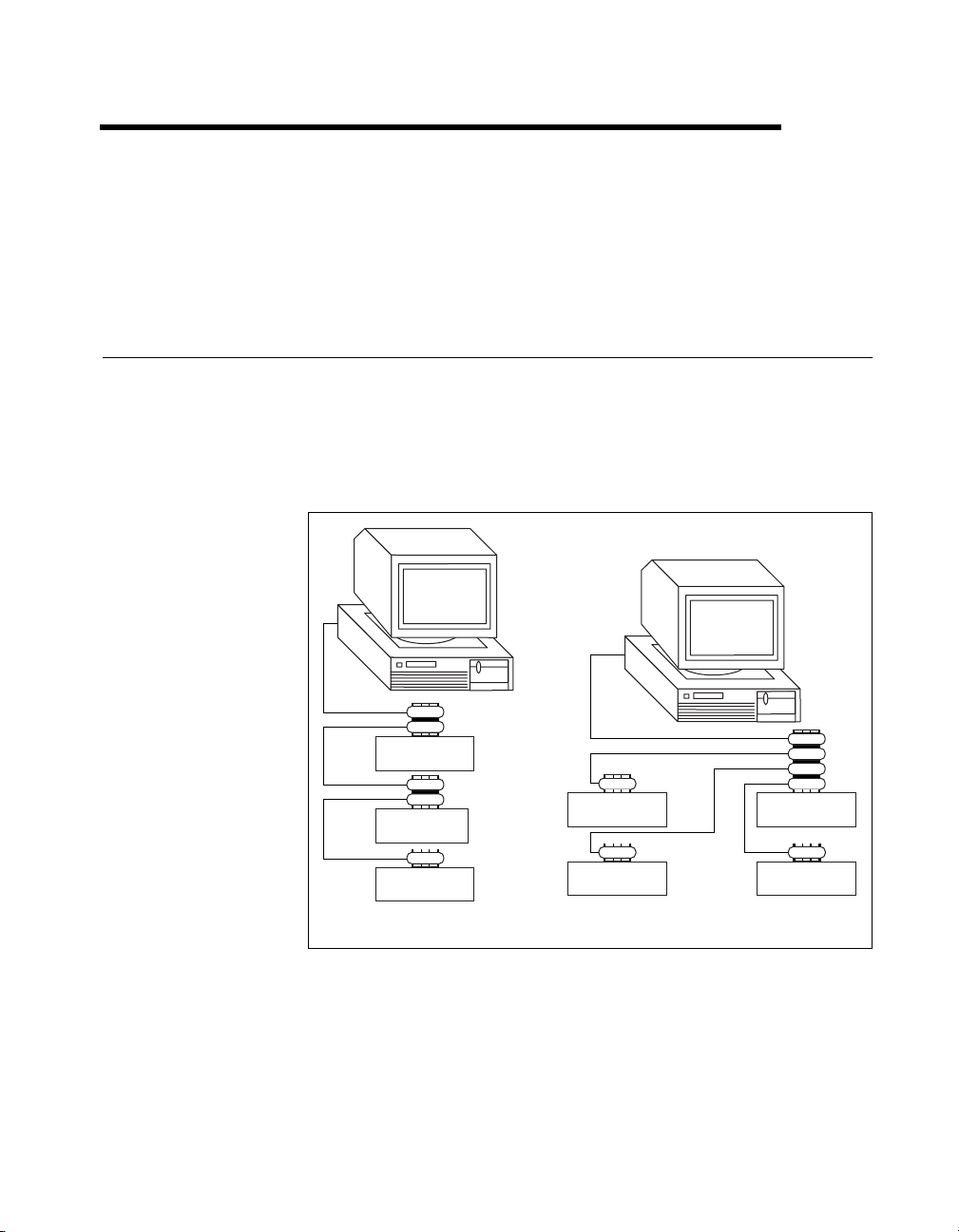
Devices are usually connected with a cable assembly consisting of a
shielded 24-conductor cable with both a plug and receptacle connector at
each end. With this design, you can link devices in a linear configuration,
a star configuration, or a combination of the two configurations. Figure 1-1
shows the linear and star configurations.
1
Device A
Device B
Device C
a. Linear Configuration
Figure 1-1.
© National Instruments Corporation 1-1 NI-488.2 User Manual for Windows
Linear and Star System Configuration
b. Star Configuration
Device DDevice A
Device CDevice B
Page 13
Chapter 1 Introduction
Controlling More Than One Interface
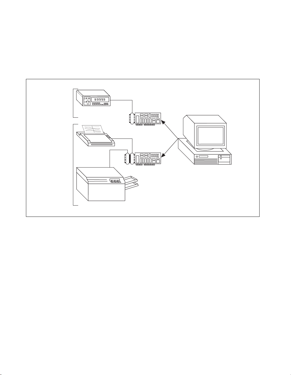
Figure 1-2 shows an example of a multiboard system configuration.
is the access interface for the voltmeter, and
for the plotter and printer. The control functions of the devices
automatically access their respective interfaces.
One
GPIB
Another
GPIB
Digital
Voltometer
gpib0
Plotter
gpib1
is the access interface
gpib1
gpib0
Printer
Figure 1-2.
Example of Multiboard System Configuration
Configuration Requirements
To achieve the high data transfer rate that the GPIB was designed for,
you must limit the number of devices on the bus and the physical distance
between devices. The following restrictions are typical:
• A maximum separation of 4 m between any two devices and an
average separation of 2 m over the entire bus.
• A maximum total cable length of 20 m.
• A maximum of 15 devices connected to each bus, with at least
two-thirds powered on.
NI-488.2 User Manual for Windows 1-2 www.natinst.com
Page 14

Chapter 1 Introduction
For high-speed operation, the following restrictions apply:
• All devices in the system must be powered on.
• Cable lengths must be as short as possible with up to a maximum of
15 m of cable for each system.
• There must be at least one equivalent device load per meter of cable.
If you want to exceed these limitations, you can use a bus extender to
increase the cable length or a bus expander to increase the number of device
loads. You can order bus extenders and expanders from National
Instruments.
© National Instruments Corporation 1-3 NI-488.2 User Manual for Windows
Page 15

Measurement & Automation
Explorer
This chapter describes Measurement & Automation Explorer,
an interactive utility you can use with the NI-488.2 software.
To start Measurement & Automation Explorer, select
Start»Programs»National Instruments NI-488.2»Explore GPIB.
Overview
You can perform the following GPIB-related tasks in Measurement &
Automation Explorer:
• Establish basic communication with your GPIB instruments.
• Scan for instruments connected to your GPIB interface.
• Launch the NI-488.2 Getting Started Wizard to get started with
GPIB instrument communication.
• Launch the NI-488.2 Troubleshooting Wizard to troubleshoot GPIB
and NI-488.2 problems.
• Launch NI Spy to monitor NI-488.2 or VISA API calls to GPIB
interfaces.
• View information about your GPIB hardware and NI-488.2 software.
• Reconfigure the GPIB interface settings.
• Locate additional help resources for GPIB and NI-488.2.
2
© National Instruments Corporation 2-1 NI-488.2 User Manual for Windows
Page 16
Chapter 2 Measurement & Automation Explorer
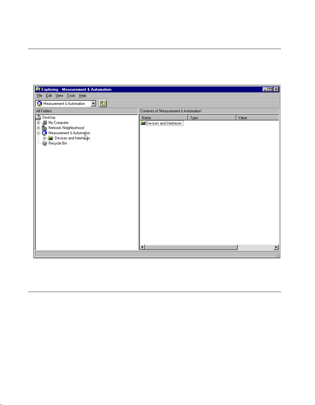
Starting Measurement & Automation Explorer
To start Measurement & Automation Explorer, select
Start»Programs»National Instruments NI-488.2»Explore GPIB.
Figure 2-1 shows Measurement & Automation Explorer.
Figure 2-1.
Measurement & Automation Explorer
Getting Started with NI-488.2
To get started with GPIB instrument communication using Measurement &
Automation Explorer, complete the following steps:
1. Refer to your Getting Started card and install the NI-488.2 software
and your GPIB hardware.
If you do not have a Getting Started card, complete the following steps
to view your getting started documentation:
a. Insert the NI-488.2 for Windows CD.
NI-488.2 User Manual for Windows 2-2 www.natinst.com
Page 17

Chapter 2 Measurement & Automation Explorer
b. When the NI-488.2 Software for Windows screen appears, select
the View Documentation option, as shown in Figure 2-2.
Figure 2-2.
Viewing Documentation on Your CD
The View Documentation Wizard helps you find the
documentation that you want to view.
2. Use the NI-488.2 Getting Started Wizard to verify the installation and
establish basic communication with your GPIB instruments.
Note
After you install the NI-488.2 software and restart your system, the NI-488.2
Getting Started Wizard runs automatically . To start it within Measurement & Automation
Explorer, select Measurement & Automation in the left window pane and select
Help»Getting Started»NI-488.2 Getting Started Wizard.
After you install the NI-488.2 software and your GPIB hardware, you can
run an existing NI-488.2 application or develop a new NI-488.2
application.
© National Instruments Corporation 2-3 NI-488.2 User Manual for Windows
Page 18

Chapter 2 Measurement & Automation Explorer
Troubleshoot NI-488.2 Problems
To troubleshoot NI-488.2 problems, run the NI-488.2 Troubleshooting
Wizard, as follows:
1. Select Start»Programs»National Instruments NI-488.2»Explore
GPIB to start Measurement & Automation Explorer.
2. Select Help»Troubleshooting»NI-488.2 Troubleshooting Wizard.
The Troubleshooting Wizard tests your GPIB interface and displays
the results, as shown in Figure 2-3.
Figure 2-3.
To view online help for the Troubleshooting Wizard, click on the Help
button.
NI-488.2 Troubleshooting Wizard
Add a New GPIB Interface
To add a new GPIB interface to your system, complete the following steps:
1. Select Start»Programs»National Instruments NI-488.2»Explore
GPIB to start Measurement & Automation Explorer.
2. Select the Devices and Interfaces folder.
3. In the right window pane, double-click on the Add Device or
Interface icon.
The Insert New dialog box appears.
4. Double-click on the GPIB Interface item.
If you are using Windows 98/95, the Add GPIB Hardware Wizard
appears. If you are using Windows 2000/NT, the NI-488.2
Configuration utility appears.
NI-488.2 User Manual for Windows 2-4 www.natinst.com
Page 19

5. Use either the Add GPIB Hardware Wizard or the NI-488.2
Configuration utility to add your interface.
Delete a GPIB Interface
Before you physically remove a GPIB interface from your system, you
must remove the hardware information, as follows:
Note
If your interface is a PCMCIA-GPIB, click on the PC Card icon on the taskbar to
stop the PC Card. When you stop the PC Card, the system removes the hardware
information from the Device Manager.
1. Select Start»Programs»National Instruments NI-488.2»Explore
GPIB to start Measurement & Automation Explorer.
2. Expand the Devices and Interfaces directory by clicking on the + next
to the folder.
3. Right-click on your GPIB interface and select Delete Interface from
the drop-down menu that appears.
4. When prompted, click on the Yes button to confirm the removal of
your interface.
Chapter 2 Measurement & Automation Explorer
Scan for GPIB Instruments
To scan for instruments connected to your GPIB interface or to add a new
instrument to your system, complete the following steps:
1. Make sure that your instrument is powered on and connected to your
GPIB interface.
2. Select Start»Programs»National Instruments NI-488.2»Explore
GPIB to start Measurement & Automation Explorer.
3. Expand the Devices and Interfaces directory by clicking on the + next
to the folder.
4. Right-click on your GPIB interface and select Scan for Instruments
from the drop-down menu that appears.
Measurement & Automation Explorer displays the connected
instruments in the right window pane.
© National Instruments Corporation 2-5 NI-488.2 User Manual for Windows
Page 20

Chapter 2 Measurement & Automation Explorer
Instruments Not Found
Instruments not Found
If the
pane, Measurement & Automation Explorer did not find any instruments.
To solve this problem, make sure that your GPIB instruments are powered
on and properly connected to the GPIB interface with a GPIB cable. Then,
scan for instruments again, as described in the previous section, Scan for
GPIB Instruments.
Instruments Enumeration Failed
Instruments Enumeration Failed
If the
window pane, Measurement & Automation Explorer found too many
Listeners on the GPIB. To solve this problem, refer to the following
possible solutions:
• If you have a running GPIB Analyzer with the GPIB handshake option
enabled, disable the GPIB handshake option in the GPIB Analyzer.
• If you have a GPIB extender in your system, Measurement &
Automation Explorer cannot detect any instruments connected to
your GPIB interface. Instead, you can verify communication with
your instruments using the Interactive Control utility. To do so,
select Tools»NI-488.2 Utilities»Interactive Control. For more
information about verifying instrument communication, type
"Interactive Control:getting started"
Control command prompt.
message appears in the right window
message appears in the right
help
at the Interactive
Communicate with Your Instrument
To establish basic or advanced communication with your instruments, refer
to the following sections.
For more information about instrument communication and a list of the
commands that your instrument understands, refer to the documentation
that came with your GPIB instrument. Most instruments respond to the
command by returning an identification string.
*IDN?
Basic Communication (Query/Write/Read)
To establish basic communication with your instrument, use the NI-488.2
Communicator, as follows:
1. If you have not already done so, scan for connected instruments as
described in the previous section, Scan for GPIB Instruments.
2. Select Start»Programs»National Instruments NI-488.2»Explore
GPIB to start Measurement & Automation Explorer.
NI-488.2 User Manual for Windows 2-6 www.natinst.com
Page 21
Chapter 2 Measurement & Automation Explorer
3. Expand the Devices and Interfaces directory by clicking on the + next
to the folder.
4. Select your GPIB interface.
Measurement & Automation Explorer displays the connected
instruments in the right window pane.
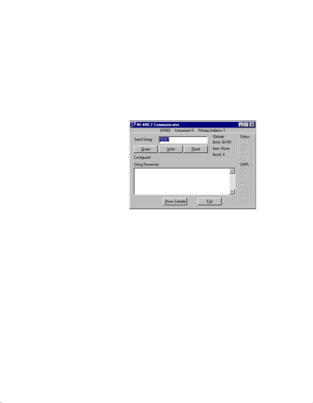
5. Right-click on your GPIB instrument and select Communicate with
Instrument from the drop-down menu that appears.
The NI-488.2 Communicator dialog box appears, as shown in
Figure 2-4.
Figure 2-4.
NI-488.2 Communicator
6. T ype a command in the Send String f ield and do one of the following:
• To write a command to the instrument then read a response back,
click on the Query button.
• To write a command to the instrument, click on the Write button.
• To read a response from the instrument, click on the Read button.
To view sample C/C++ code that performs a simple query of a GPIB
instrument, click on the Show Sample button.
Advanced Communication
For advanced interactive communication with GPIB instruments, use the
Interactive Control utility, as follows:
1. Select Start»Programs»National Instruments NI-488.2»Explore
GPIB to start Measurement & Automation Explorer.
2. Expand the Devices and Interfaces directory by clicking on the + next
to the folder.
© National Instruments Corporation 2-7 NI-488.2 User Manual for Windows
Page 22

Chapter 2 Measurement & Automation Explorer
3. Right-click on your GPIB interface and select Interactive Control
from the drop-down menu that appears.
4. At the command prompt, type NI-488.2 API calls to communicate
interactively with the your instrument. For example, you might use
ibdev, ibclr, ibwrt, ibrd
, and
ibonl
.
T o view the online help for Interacti ve Control, type
Control command prompt.
help
View NI-488.2 Software Version
To view the NI-488.2 software version, complete the following steps:
1. Select Start»Programs»National Instruments NI-488.2»Explore
GPIB to start Measurement & Automation Explorer.
2. Select Help»About Measurement & Automation Explorer.
The Value column in the About Measurement & Automation
Explorer dialog box displays the version number of the NI-488.2
software.
Monitor, Record, and Display NI-488.2 Calls
To monitor NI-488.2 calls, use NI Spy, as follows:
1. Select Start»Programs»National Instruments NI-488.2»Explore
GPIB to start Measurement & Automation Explorer.
2. Expand the Devices and Interfaces directory by clicking on the + next
to the folder.
3. Right-click on your GPIB interface and select NI Spy from the
drop-down menu that appears.
4. On the NI Spy toolbar, click on the blue arrow button to start a capture.
5. Start the NI-488.2 application that you want to monitor.
at the Interactive
NI-488.2 User Manual for Windows 2-8 www.natinst.com
Page 23
Chapter 2 Measurement & Automation Explorer
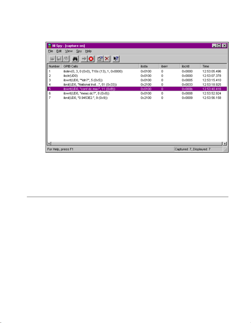
NI Spy records and displays all NI-488.2 calls, as shown in Figure 2-5.
Figure 2-5.
For more information about using NI Spy, select Help»Help Topics in
NI Spy or refer to Chapter 5, NI Spy Utility.
NI-488.2 Calls Recorded by NI Spy
View or Change GPIB Interface Settings
To view or change the settings of your GPIB interface, refer to one of the
following sections.
Windows 98/95
To view or change your interface settings in Windows 98/95, complete the
following steps:
1. Select Start»Programs»National Instruments NI-488.2»Explore
GPIB to start Measurement & Automation Explorer.
2. Expand the Devices and Interfaces directory by clicking on the + next
to the folder.
3. Right-click on your GPIB interface and select Properties from the
drop-down menu that appears.
© National Instruments Corporation 2-9 NI-488.2 User Manual for Windows
Page 24
Chapter 2 Measurement & Automation Explorer
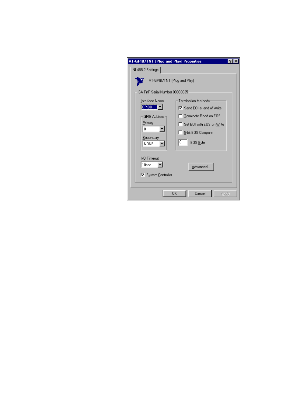
The Properties dialog box appears. Figure 2-6 shows the Properties
dialog box for an AT-GPIB/TNT (Plug and Play) interface.
Figure 2-6. Properties Dialog Box in Windows 98/95
If you need more information about a field in the Properties dialog
box, click on the ? button in the upper-right corner of the dialog box,
then click on the field.
4. (Optional) Change the settings for your interface.
Windows 2000/NT
To view or change GPIB interface information, complete the following
steps:
1. Select Start»Programs»National Instruments NI-488.2»Explore
GPIB to start Measurement & Automation Explorer.
2. Expand the Devices and Interfaces directory by clicking on the + next
to the folder.
3. Right-click on your GPIB interface and select Properties from the
drop-down menu that appears.
NI-488.2 User Manual for Windows 2-10 www.natinst.com
Page 25

Chapter 2 Measurement & Automation Explorer
The GPIB Configuration dialog box appears. Figure 2-7 shows the
GPIB Configuration dialog box for an AT-GPIB/TNT (Plug and
Play) interface in Windows NT.
Figure 2-7.
4. Select your GPIB Board and click on the Configure button.
5. (Optional) Change the settings for your interface.
For more information about changing the settings for your interface, click
on the Help button.
GPIB Configuration Utility in Windows NT
View GPIB Instrument Information
To view information about your GPIB instruments, complete the following
steps:
1. If you have not already done so, scan for connected instruments as
described in the Scan for GPIB Instruments section earlier in this
chapter.
2. Select Start»Programs»National Instruments NI-488.2»Explore
GPIB to start Measurement & Automation Explorer.
3. Expand the Devices and Interfaces directory by clicking on the + next
to the folder.
4. Select your GPIB interface.
Measurement & Automation Explorer displays the connected
instruments in the right window pane. Table 2-1 describes the
© National Instruments Corporation 2-11 NI-488.2 User Manual for Windows
Page 26

Chapter 2 Measurement & Automation Explorer
instrument information that Measurement & Automation Explorer
displays.
Table 2-1.
Measurement & Automation Explorer Instrument Information
Column Description
Name Logical instrument name assigned by Measurement &
Automation Explorer
Type Instrument’s response to the identification query
(
*IDN?
)
Value Primary (PAD) and secondary (SAD) addresses of the
instrument
Description Identifies the instrument as a GPIB instrument
Change GPIB Device Templates
For older NI-488.2 applications, you might need to modify one o f the
device templates to find a given GPIB instrument by name, for example,
ibfind("fluke45")
preferred
ibfind
ibdev
ibdev
to obtain device handles and use
to dynamically configure your GPIB device handle.
eliminates unneccessary device name requirements.
If you must modify a device template, refer to one of the following sections.
. Older applications still use
to obtain a device handle. In new applications, avoid using
ibfind
instead. You can use
ibdev
instead of the
also
ibdev
Windows 98/95
To reconfigure GPIB device templates in Windows 98/95, complete the
following steps:
1. Select Start»Settings»Control Panel.
2. Double-click on the System icon.
3. Select the Device Manager tab and click on the View devices by type
button.
4. Click on the National Instruments GPIB Interfaces icon.
5. Click on the Properties button.
6. Select the Device Templates tab and rename the template as described
in your application documentation.
7. Click on the OK button twice to save your changes and exit.
NI-488.2 User Manual for Windows 2-12 www.natinst.com
Page 27

Chapter 2 Measurement & Automation Explorer
Windows 2000/NT
To reconfigure GPIB device templates in Windows 2000/NT, complete the
following steps:
1. Select Start»Programs»National Instruments NI-488.2»Explore
GPIB to start Measurement & Automation Explorer.
2. Expand the Devices and Interfaces directory by clicking on the + next
to the folder.
3. Right-click on any GPIB interface and select Properties from the
drop-down menu that appears.
4. Select the device template that you want to modify, such as DEV1.
5. Click on the Configure button and rename the device template as
described in your application documentation.
6. Click on the OK button twice to save your changes and exit.
Enable/Disable NI-488.2 DOS Support
To enable or disable DOS support for your NI-488.2 application, refer to
one of the following sections.
Windows 98/95
To enable or disable NI-488.2 DOS support in Windows 98/95, complete
the following steps:
1. Make sure that no older version of the NI-488.2 DOS device driver is
being loaded from your
following steps:
a. Locate your
b. Find the following line:
device=<path>\gpib.com
where
<path>
is located.
c. If that line appears, type
follows:
REM device=<path>\gpib.com
d. Save your
2. Select Start»Programs»National Instruments NI-488.2»Explore
GPIB to start Measurement & Automation Explorer.
© National Instruments Corporation 2-13 NI-488.2 User Manual for Windows
config.sys
config.sys
config.sys
refers to the drive and directory where
REM
file and close it.
file. To do so, complete the
file and open it for editing.
gpib.com
at the beginning of the line, as
Page 28

Chapter 2 Measurement & Automation Explorer
3. Expand the Devices and Interfaces directory by clicking on the + next
to the folder.
4. Click on your GPIB interface and select Tools»Settings»NI-488.2
from the Explorer menu.
5. Enable or disable DOS support in the NI-488.2 Settings dialog box
and click on the OK button.
6. If you are prompted to do so, restart your system.
Windows 2000/NT
To enable NI-488.2 DOS support in Windows 2000/NT, complete the
following steps:
1. Open your
directory (for example,
2. Find the following lines:
REM ***To run DOS GPIB applications, uncomment the
REM ***following line
REM device=<path>\doswin16\gpib-nt.com
where
<path>
software.
3. Remove
device=<path>\doswin16\gpib-nt.com
config.nt
is the directory in which you installed the NI-488.2
from the last line so that it reads as follows:
REM
file, located in the Windows NT system32
c:\windows\system32
).
To disable DOS support, add
back to the line where it was removed.
REM
Access Additional Help and Resources
To access additional help and resources for the NI-488.2 software and your
GPIB hardware, refer to the following sections.
NI-488.2 Online Help
The NI-488.2 for Windows Online Help addresses questions you might
have about NI-488.2, includes troubleshooting information, and describes
the NI-488.2 API. You can access the NI-488.2 online help as follows:
1. Select Start»Programs»National Instruments NI-488.2»Explore
GPIB to start Measurement & Automation Explorer.
2. Expand the Devices and Interfaces directory by clicking on the + next
to the folder.
NI-488.2 User Manual for Windows 2-14 www.natinst.com
Page 29

Chapter 2 Measurement & Automation Explorer
3. Right-click on your GPIB interface and select NI-488.2 Help from the
drop-down menu that appears.
National Instruments GPIB Web Site
To access the National Instruments Web site for GPIB, select
Start»Programs»National Instruments NI-488.2»Explore GPIB to
start Measurement & Automation Explorer. Then, select Help»National
Instruments on the Web»GPIB Home Page.
View or Change GPIB-ENET Network Settings
(Windows 98/95 Only)
To view or change the network settings of your GPIB-ENET, refer to the
following sections. For more information about your GPIB-ENET network
settings, refer to the Getting Started with Your GPIB-ENET and the
NI-488.2 Software for Windows 98/95 manual.
Assign IP Address
You can run the Assign IP Address utility in Measurement & Automation
Explorer, as follows:
1. Contact your network administrator to determine whether you should
use the Assign IP Address utility to assign the IP address manually.
2. Select Start»Programs»National Instruments NI-488.2»Explore
GPIB to start Measurement & Automation Explorer.
3. Expand the Devices and Interfaces directory by clicking on the + next
to the folder.
4. Right-click on your GPIB-ENET interface and select Assign IP
Address from the drop-down menu that appears.
To view the built-in, context-sensitive help for the Assign IP Address
utility, click on the Help button.
Configure Advanced IP Settings
You can run the Advanced IP Settings utility in Measurement &
Automation Explorer, as follows:
1. Contact your network administrator.
2. Select Start»Programs»National Instruments NI-488.2»Explore
GPIB to start Measurement & Automation Explorer.
© National Instruments Corporation 2-15 NI-488.2 User Manual for Windows
Page 30

Chapter 2 Measurement & Automation Explorer
3. Expand the Devices and Interfaces directory by clicking on the + next
to the folder.
4. Right-click on your GPIB-ENET interface and select Advanced IP
Settings from the drop-down menu that appears.
To view the built-in, context-sensitive help for the Advanced IP Settings
utility, click on the Help button.
Update GPIB-ENET Firmware
You can run the Update Firmware utility in Measurement & Automatio n
Explorer, as follows:
1. Select Start»Programs»National Instruments NI-488.2»Explore
GPIB to start Measurement & Automation Explorer.
2. Expand the Devices and Interfaces directory by clicking on the + next
to the folder.
3. Right-click on your GPIB-ENET interface and select Update
Firmware from the drop-down menu that appears.
T o view the b uilt-in, context-sensitiv e help for the Update Firmware utility ,
click on the Help button.
NI-488.2 User Manual for Windows 2-16 www.natinst.com
Page 31

Developing Your NI-488.2
Application
This chapter describes how to develop an NI-488.2 application using the
NI-488.2 API.
Simple Instrument Control
To establish basic communication with your instrument, use the NI-488.2
Communicator, as follows:
1. If you have not already done so, scan for connected instruments as
described in the Scan for GPIB Instruments section in Chapter 2,
Measurement & Automation Explorer.
2. Select Start»Programs»National Instruments NI-488.2»Explore
GPIB to start Measurement & Automation Explorer.
3. Expand the Devices and Interfaces directory by clicking on the + next
to the folder.
4. Select your GPIB interface.
Measurement & Automation Explorer displays the connected
instruments in the right window pane.
5. Right-click on your GPIB instrument and select Communicate with
Instrument from the drop-down menu that appears.
3
© National Instruments Corporation 3-1 NI-488.2 User Manual for Windows
Page 32

Chapter 3 Developing Your NI-488.2 Application
The NI-488.2 Communicator dialog box appears, as shown in
Figure 3-1.
6. T ype a command in the Send String f ield and do one of the following:
• To write a command to the instrument then read a response back,
click on the Query button.
• To write a command to the instrument, click on the Write button.
• To read a response from the instrument, click on the Read button.
Figure 3-1. NI-488.2 Communicator
To view sample C/C++ code that performs a simple query of a GPIB
instrument, click on the Show Sample button.
Interactive Instrument Control
Before you write your NI-488.2 application, you might want to use the
Interactive Control utility to communicate with your instruments
interactively by typing individual commands rather than issuing them from
an application. You can also use the Interactive Control utility to learn to
communicate with your instruments using the NI-488.2 API. For specific
device communication instructions, refer to the documentation that came
with your instrument. For information about using the Interactive Control
utility and detailed examples, refer to Chapter 6, Interactive Control
Utility.
NI-488.2 User Manual for Windows 3-2 www.natinst.com
Page 33

Chapter 3 Developing Your NI-488.2 Application
For advanced interactive communication with GPIB instruments, use the
Interactive Control utility, as follows:
1. Select Start»Programs»National Instruments NI-488.2»Explore
GPIB to start Measurement & Automation Explorer.
2. Expand the Devices and Interfaces directory by clicking on the + next
to the folder.
3. Right-click on your GPIB interface and select Interactive Control
from the drop-down menu that appears.
4. At the command prompt, type NI-488.2 API calls to communicate
interactively with the your instrument. For example, you might use
ibdev, ibclr, ibwrt, ibrd
, and
ibonl
.
T o view the online help for Interacti ve Control, type
Control command prompt. For more information, refer to Chapter 6,
Interactive Control Utility.
Choosing Your Programming Methodology
Based on your development environment, you can select a method for
accessing the driver, and based on your NI-488.2 programming needs, you
can choose how to use the NI-488.2 API.
Choosing a Method to Access the NI-488.2 Driver
Applications can access the NI-488.2 dynamic link library (DLL),
gpib-32.dll
access.
NI-488.2 Language Interfaces
You can use a language interface if your program is written in Microsoft
Visual C/C++ (2.0 or later), Borland C/C++ (4.0 or later) , or Microsoft
Visual Basic (4.0 or later). Otherwise, you must access
directly.
Direct Entry Access
You can access the DLL directly from any programming environment that
allows you to request addresses of variables and functions that a DLL
exports.
all the NI-488.2 calls.
, either by using an NI-488.2 language interface or by direct
gpib-32.dll
exports pointers to each of the global variables and
at the Interactive
help
gpib-32.dll
© National Instruments Corporation 3-3 NI-488.2 User Manual for Windows
Page 34

Chapter 3 Developing Your NI-488.2 Application
Choosing How to Use the NI-488.2 API
The NI-488.2 API has two subsets of calls to meet your application needs.
Both of these sets, the traditional calls and the multi-device calls, are
compatible across computer platforms and operating systems, so you can
port programs to other platforms with little or no source code modification.
For most applications, the traditional NI-488 .2 calls are sufficient. If you
have a complex configuration with one or more interfaces and multiple
devices, use the multi-device NI-488.2 calls. Whichever option you
choose, bus management operations necessary for device communication
are performed automatically.
The following sections describe some differences between the traditional
NI-488.2 calls and the multi-device NI-488.2 calls.
Communicating with a Single GPIB Device
If your system has only one device attached to each interface, the traditional
NI-488.2 calls are probably sufficient for your programming needs. A
typical NI-488.2 application with a single device has three phases:
• Initialization: use
device.
• Device Communication: use
ibwait
to communicate with the device.
• Cleanup: use
ibdev
to put the handle offline.
ibonl
to get a handle and use
ibwrt, ibrd, ibtrg
ibclr
,
ibrsp
to clear the
, and
Refer to the sample applications that are installed with the NI-488.2
software to see detailed examples for different GPIB device types.
For NI-488.2 applications that need to control the GPIB in non-typical
ways, for example, to communicate with non-compliant GPIB devices,
there are a set of low-level functions that per fo rm rudimentary GPIB
applications. If you use these functions, you need to understand GPIB
management details like how to address talkers and listeners. Refer to
Appendix A, GPIB Basics, for some details on GPIB management.
The set of low-lev el functions are called board-lev el functions. They access
the interface directly and require you to handle the addressing and bus
management protocol. These functions give you the flexibility and control
to handle situations such as the following:
• Communicating with non-compliant (non-IEEE 488.2) devices.
• Altering various low-level interface configurations.
• Managing the bus in non-typical ways.
NI-488.2 User Manual for Windows 3-4 www.natinst.com
Page 35

Chapter 3 Developing Your NI-488.2 Application
Board-level functions that an NI-488.2 application might use include the
following—
ibcmd, ibrd, ibwrt
, and
ibconfig
. For a detailed list, refer
to the NI-488.2 online help. For instructions on accessing the online help,
refer to the Using the NI-488.2 Documentation section in About This
Manual.
Using Multiple Interfaces and/or Multiple Devices
When your system includes an interface that must access multiple devices,
use the multi-device NI-488.2 calls, which can perform the following tasks
with a single call:
• Find the Listeners on the bus using
• Find a device requesting service using
FindLstn
FindRQS
• Determine the state of the SRQ line, or wait for SRQ to be asserted
using
TestSRQ
or
WaitSRQ
.
• Address multiple devices to receive a command using
You can mix board-level traditional NI-488.2 calls with the multi-device
NI-488.2 calls to have access to all the NI-488.2 functionality.
.
.
SendList
.
Checking Status with Global Variables
Each NI-488.2 API call updates four global variables to reflect the status of
the device or interface that you are using. These global status variables are
Note
If your application is a multithreaded application, refer to the section Writing
Multithreaded Win32 NI-488.2 Applications in Chapter 7, NI-488.2 Programming
Techniques.
Status Word (ibsta)
the status word (
variables (
ibcnt
performance of your application. Your application should check these
variables after each NI-488.2 call. The following sections describe each of
these global variables and how you can use them in your application.
All NI-488.2 calls update a global status word,
information about the state of the GPIB and the GPIB hardware. The value
stored in
except
ibsta
ibfind
and
and use that information to make decisions about continued processing. If
), the error variable (
ibsta
and
ibcntl
). They contain useful information about the
is the return value of all the traditional NI-488.2 calls,
. You can examine various status bits in
ibdev
), and the count
iberr
ibsta
, which contains
ibsta
© National Instruments Corporation 3-5 NI-488.2 User Manual for Windows
Page 36

Chapter 3 Developing Your NI-488.2 Application
you check for possible errors after each call using the
ibsta
ERR bit,
debugging your application is much easier.
is a 16-bit value. A bit value of one (1) indicates that a certain
ibsta
condition is in effect. A bit value of zero (0) indicates that the condition is
not in effect. Each bit in
can be set for device-level traditional
ibsta
NI-488.2 calls (dev), board-level traditional NI-488.2 calls and
multi-device NI-488.2 calls (brd), or all (dev, brd).
Table 3-1 shows the condition that each bit position represents, the bit
mnemonics, and the type of calls for which the bit can be set. For a detailed
explanation of each status condition, refer to Appendix B, Status Word
Conditions.
Table 3-1. Status Word Layout
Mnemonic
Bit
Pos
Hex
Value
Type Description
ERR 15 8000 dev, brd NI-488.2 error
TIMO 14 4000 dev, brd Time limit exceeded
END 13 2000 dev, brd END or EOS detected
SRQI 12 1000 brd SRQ interrupt received
RQS 11 800 dev Device requesting
service
CMPL 8 100 dev, brd I/O completed
LOK 7 80 brd Lockout State
REM 6 40 brd Remote State
CIC 5 20 brd Controller-In-Charge
ATN 4 10 brd Attention is asserted
TACS 3 8 brd Talker
LACS 2 4 brd Listener
DTAS 1 2 brd Device Trigger State
DCAS 0 1 brd Device Clear State
NI-488.2 User Manual for Windows 3-6 www.natinst.com
Page 37

Chapter 3 Developing Your NI-488.2 Application
The language header file defines each of the
for an
status bit being set using the bitwise
ibsta
C/C++). For example, the
To check for an NI-488.2 error, use the following statement after each
NI-488.2 call:
if (ibsta & ERR)
printf("NI-488.2 error encountered");
Error Variable (iberr)
If the ERR bit is set in
error occurs, the error type is specified by
error, use the following statement after each NI-488.2 call:
if (ibsta & ERR)
printf("NI-488.2 error %d encountered", iberr);
Note
The value in
, indicating that an error has occurred.
ibsta
is meaningful as an error type only when the ERR bit is set in
iberr
For more information about error codes and solutions, refer to Chapter 4,
Debugging Your Application, or Appendix C, Error Codes and Solutions.
Count Variables (ibcnt and ibcntl)
The count variables are updated after each read, write, or command
function. In Win32 applications,
On some systems, like MS-DOS,
a 32-bit integer. For cross-platform compatibility, all applicat ions should
use
ibcntl
number of bytes read. If you are sending data or commands, the count
variables reflect the number of bytes sent.
. If you are reading data, the count variables indicate the
status bits. Y ou can test
ibsta
operator (& in
and
ERR bit is bit 15 of
ibsta
, an NI-488.2 error has occurred. When an
ibsta
iberr
and
ibcnt
ibcnt
ibcntl
is a 16-bit integer, and
ibsta
. To check for an NI-488.2
are 32-bit integers.
.
ibcntl
is
Using Interactive Control to Communicate with Devices
Before you begin writing your application, you might want to use the
Interactive Control utility to communicate with your instruments
interactively by typing in commands from the keyboard rather than from an
application. You can use the Interactive Control utility to learn to
communicate with your instruments using the NI-488.2 API. For specific
device communication instructions, refer to the user manual that came with
your instrument. For information about using the Interactive Control utility
and detailed examples, refer to Chapter 6, Interactive Control Utility.
© National Instruments Corporation 3-7 NI-488.2 User Manual for Windows
Page 38

Chapter 3 Developing Your NI-488.2 Application
Programming Models
Applications That Communicate with a Single GPIB Device
This section describes items you should include in your application and
provides general program steps with an NI-488.2 example.
Items to Include
Include the following items in your application:
• Header files—In a C application, include the header files
and
decl-32.h
contains definitions used by
prototypes for the NI-488.2 calls and constants that you can use in your
application.
• Error checking—Check for errors after each NI-488.2 call.
• Error handling—Declare and define a function to handle NI-488.2
errors. This function takes the device of fline and closes the application.
If the function is declared as:
void gpiberr (char * msg); /*function prototype*/
Then, your application invokes it as follows:
if (ibsta & ERR) {
gpiberr("NI-488.2 error");
}
. The standard Windows header file,
decl-32.h
, and
decl-32.h
windows.h
windows.h
contains
,
General Program Steps and Examples
The following steps show you how to use the device-level traditional
NI-488.2 calls in your application. The NI-488.2 software includes the
source code for an example written in C,
for the example written to use direct entry to access
dlldevquery.c
written in Visual Basic,
. The NI-488.2 software also includes a sample program
devquery.frm
devquery.c
.
Initialization
Step 1. Open a Device
Use
following parameters:
• Connect board index (typically 0, for
• Primary address for the GPIB instrument (refer to the instrument user
NI-488.2 User Manual for Windows 3-8 www.natinst.com
to open a device handle. The
ibdev
manual or use the
FindLstn
ibdev
GPIB0
function to dynamically determine the
, and the source code
gpib-32.dll
function requires the
).
,
Page 39

Chapter 3 Developing Your NI-488.2 Application
GPIB address of your GPIB device, as described in Step 2. Determine
the GPIB Address of Your Device in the section Applications That Use
Multiple Interfaces or Communicate with Multiple GPIB Devices later
in this chapter).
• Secondary address for the GPIB instrument (0 if the GPIB instrument
does not use secondary addressing).
• Timeout period (typically set to T10s, which is 10 seconds).
• End-of-transfer mode (typically set to 1 so that EOI is asserted with the
last byte of writes).
• EOS detection mode (typically 0 if the GPIB instrument does not use
EOS characters).
A successful
call returns a device handle, ud, that is used for all
ibdev
device-level traditional NI-488.2 calls that communicate with the GPIB
instrument.
Step 2. Clear the Device
Use
to clear the device. This resets the device’s internal functions to
ibclr
the default state.
Device Communication
Step 3. Communicate with the Device
Communicate with the device by sending it the
"*IDN?"
reading back the response. Many devices respond to this query by returning
a description of the device. Refer to the documentation that came with your
GPIB device to see specific instructions on the proper way to communicate
with it.
Step 3a.
Use
ibwrt
to send the
"*IDN?"
query command to the device.
Step 3b.
to read the response from the device.
ibrd
Use
query and then
Continue communicating with the GPIB device until you are finished.
Cleanup
Step 4. Place the Device Offline before Exiting Your Application
Use
© National Instruments Corporation 3-9 NI-488.2 User Manual for Windows
to put the device handle offline before you exit the application.
ibonl
Page 40

Chapter 3 Developing Your NI-488.2 Application
Applications That Use Multiple Interfaces or Communicate with
Multiple GPIB Devices
This section describes items you should include in your application and
provides general program steps with an NI-488.2 example.
Items to Include
Include the following items in your application:
• Header files—In a C application, include the header files
and
decl-32.h
contains definitions used by
. The standard Windows header file,
decl-32.h
, and
decl-32.h
prototypes for the NI-488.2 calls and constants that you can use in your
application.
• Error checking—Check for errors after each NI-488.2 call.
• Error handling—Declare and define a function to handle NI-488.2
errors. This function takes the device of fline and closes the application.
If the function is declared as:
void gpiberr (char * msg); /*function prototype*/
Then your application invokes it as follows:
if (ibsta & ERR) {
gpiberr("NI-488.2 error");
}
windows.h
windows.h
,
contains
General Program Steps and Examples
The following steps show you how to use the multi-device NI-488.2 calls
in your application. The NI-488.2 software includes the source code for an
example written in C,
4882query.c
written to use direct entry to access the
The NI-488.2 software also includes a sample program written in Visual
Basic,
query4882.frm
.
Initialization
Step 1. Become Controller-In-Charge (CIC)
Use
SendIFC
interface is Controller-In-Charge (CIC). The only argument of
the GPIB interface number, typically 0 for
NI-488.2 User Manual for Windows 3-10 www.natinst.com
to initialize the bus and the GPIB interface so that the GPIB
, and the source code for the example
gpib-32.dll, dll4882query.c
is
GPIB0
SendIFC
.
.
Page 41

Chapter 3 Developing Your NI-488.2 Application
Step 2. Determine the GPIB Address of Your Device
Use
FindLstn
to find all the devices attached to the GPIB. The
FindLstn
function requires the following parameters:
• Interface number (typically 0, for
• A list of primary addresses, terminated with the
GPIB0
).
NOADDR
constant.
• A list for reported GPIB addresses of devices found listening on the
GPIB.
• Limit, which is the number of the GPIB addresses to report.
Use
FindLstn
to test for the presence of all of the primary addresses that
are passed to it. If a device is present at a particular primary address, then
the primary address is stored in the GPIB addresses list. Otherwise, all
secondary addresses of the given primary address are tested, and the GPIB
address of any devices found are stored in the GPIB addresses list. When
you have the list of GPIB addresses, you can determine which one
corresponds to your instrument and use it for subsequent calls.
Alternately, if you already know your GPIB device’s primary and
secondary address, you can create an appropriate GPIB address to use in
subsequent NI-488.2 calls, as follows: a GPIB address is a 16-bit v alue that
contains the primary address in the low byte and the secondary address in
the high byte. If you are not using secondary addressing, the secondary
address is 0. For example, if the primary address is 1, then the 16-bit value
is 0x01; otherwise, if the primary address is 1 and the secondary address is
0x67, then the 16-bit value is 0x6701.
Step 3. Initialize the Devices
Use
DevClearList
to clear the devices on the GPIB. The first argument
is the GPIB interface number. The second argument is the list of GPIB
addresses that were found to be listening as determined in Step 2.
Device Communication
Step 4. Communicate with the Devices
Communicate with the devices by sending them the
"*IDN?"
then reading back the responses. Many devices respond to this query by
returning a description of the device. Refer to the documentation that came
with your GPIB devices to see specific instruction on the proper way to
communicate with them.
query and
© National Instruments Corporation 3-11 NI-488.2 User Manual for Windows
Page 42

Chapter 3 Developing Your NI-488.2 Application
Step 4a.
Use
SendList
devices. The address is the list of GPIB devices to be queried. The buffer
that you pass to
Step 4b.
Use
Receive
Continue communicating with the GPIB devices until you are finished.
to send the
SendList
for each device to read the responses from each device.
"*IDN?"
is the command message to the device.
query command to multiple GPIB
Cleanup
Step 5. Place the Interface Offline before Exiting Your Application
Use
to put the interface offline before you exit the application.
ibonl
Language-Specific Programming Instructions
The following sections describe how to develop, compile, and link your
Win32 NI-488.2 applications using various programming languages.
Microsoft Visual C/C++ (Version 2.0 or Later)
Before you compile your Win32 C application, make sure that the
following lines are included at the beginning of your program:
#include <windows.h>
#include "decl-32.h"
To compile and link a Win32 console application named
shell, type the following on the command line:
cl cprog.c gpib-32.obj
Borland C/C++ (Version 4.0 or Later)
Before you compile your Win32 C application, make sure that the
following lines are included at the beginning of your program:
#include <windows.h>
#include "decl-32.h"
To compile and link a Win32 console application named
shell, type the following on the command line:
bcc32 -w32 cprog.c borlandc_gpib-32.obj
cprog
cprog
in a DOS
in a DOS
NI-488.2 User Manual for Windows 3-12 www.natinst.com
Page 43

Visual Basic (Version 4.0 or Later)
With Visual Basic, you can access the traditional NI-488.2 calls as
subroutines, using the BASIC keyword
NI-488.2 call name, or you can access them using the
With some of the NI-488.2 calls (for example
length of the string buffer is automatically calculated within the actual
function or subroutine, which eliminates the need to pass in the length as
an extra parameter. For more information about function syntax for Visual
Basic, refer to the NI-488.2 online help. For instructions on accessing the
online help, refer to the Using the NI-488.2 Documentation section in
About This Manual.
Chapter 3 Developing Your NI-488.2 Application
followed by the traditional
CALL
set of functions.
il
ibrd
and
Receive
), the
Direct Entry with C
Before you run your V isual Basic application, include the
and
vbib-32.bas
files in your application project file.
niglobal.bas
The following sections describe how to use direct entry with C.
gpib-32.dll Exports
gpib-32.dll
NI-488.2 calls. Pointers to the global variables (
and
ibcntl
int *user_ibsta;
int *user_iberr;
int *user_ibcnt;
long *user_ibcntl;
Except for the functions
the NI-488.2 call names are exported from
direct entry to access a particular function and to get a pointer to the
exported function, you just need to call
name of the function as a parameter. For more information about the
parameters to use when you invoke the function, refer to the NI-488.2
online help. For instructions on accessing the online help, refer to the
Using the NI-488.2 Documentation section in About This Manual.
exports pointers to the global variables and all of the
ibsta, iberr, ibcnt
) are accessible through these exported variables:
ibbna, ibfind, ibrdf
GetProcAddress
, and
ibwrtf
gpib-32.dll
. Thus, to use
passing the
, all
,
The functions
argument that is a name.
ibbna, ibfind, ibrdf
ibbna
requires an interface or device name, and
, and
ibwrtf
all require an
requires an interface name,
and
ibrdf
ibwrtf
ibfind
require a file
name. Because Windows 2000/NT supports both normal (8-bit) and
Unicode (16-bit) characters,
gpib-32.dll
exports both normal and
Unicode versions of these functions. Because Windows 98/95 does not
© National Instruments Corporation 3-13 NI-488.2 User Manual for Windows
Page 44

Chapter 3 Developing Your NI-488.2 Application
support 16-bit wide characters, use only the 8-bit ASCII versions, named
ibbnaA, ibfindA, ibrdfA
named
ibbnaW, ibfindW, ibrdfW
Unicode or ASCII versions of these functions with Windows 2000/NT, but
only the ASCII versions with Windows 98/95.
In addition to pointers to the status variables and a handle to the loaded
gpib-32.dll
functions you use in your application. For the prototypes for each function
exported by
instructions on accessing the online help, refer to the Using the NI-488.2
Documentation section in About This Manual.
The direct entry sample programs illustrate how to use direct entry to
access
gpib-32.dll
online help for your development environment.
Directly Accessing the gpib-32.dll Exports
Make sure that the following lines are included at the beginning of your
application:
#ifdef __cplusplus
extern "C"{
#endif
, and
ibwrtfA
, and
. The Unicode versions are
ibwrtfW
. You can use either the
, you must define the direct ent ry prototypes for the
gpib-32.dll
, refer to the NI-488.2 online help. For
. For more information about direct entry, refer to the
#include <windows.h>
#include "decl-32.h"
#ifdef __cplusplus
}
#endif
In your Win32 application, you need to load
accessing the
gpib-32.dll
you how to call the
LoadLibrary
exports. The following code fragment shows
function to load
gpib-32.dll
gpib-32.dll
before
and
check for an error:
HINSTANCE Gpib32Lib = NULL;
Gpib32Lib=LoadLibrary("GPIB-32.DLL");
if (Gpib32Lib == NULL) {
return FALSE;
}
NI-488.2 User Manual for Windows 3-14 www.natinst.com
Page 45

Chapter 3 Developing Your NI-488.2 Application
For the prototypes for each function, refer to the NI-488.2 online help. For
instructions on accessing the online help, refer to the Using the NI-488.2
Documentation section in About This Manual.
For functions that return an integer value, like
ibdev
or
ibwrt
, the pointer
to the function needs to be cast as follows:
int (_stdcall *Pname)
where
*Pname
do not return a value, like
is the name of the pointer to the function. For functions that
FindLstn
or
SendList
, the pointer to the
function needs to be cast as follows:
void (_stdcall *Pname)
where
*Pname
is the name of the pointer to the function. They are followed
by the function’s list of parameters as described in the NI-488.2 online help.
For instructions on accessing the online help, refer to the Using the
NI-488.2 Documentation section in Abou t This Manual.
Following is an example of how to cast the function pointer and how the
parameter list is set up for
int (_stdcall *Pibdev)(int ud, int pad, int sad, int tmo,
int eot, int eos);
int (_stdcall *Pibonl)(int ud, int v);
Next, your Win32 application needs to use
ibdev
and
functions:
ibonl
GetProcAddress
to get the
addresses of the global status variables and functions your application
needs. The following code fragment shows you ho w to get the addresses of
the pointers to the status variables and any functions your application
needs:
/* Pointers to NI-488.2 global status variables */
int *Pibsta;
int *Piberr;
long *Pibcntl;
static int(__stdcall *Pibdev)
(int ud, int pad, int sad, int tmo, int eot,
int eos);
static int(__stdcall *Pibonl)
(int ud, int v);
Pibsta = (int *) GetProcAddress(Gpib32Lib,
(LPCSTR)"user_ibsta");
Piberr = (int *) GetProcAddress(Gpib32Lib,
(LPCSTR)"user_iberr");
© National Instruments Corporation 3-15 NI-488.2 User Manual for Windows
Page 46

Chapter 3 Developing Your NI-488.2 Application
Pibcntl = (long *) GetProcAddress(Gpib32Lib,
(LPCSTR)"user_ibcnt");
Pibdev = (int (__stdcall *)
(int, int, int, int, int, int))
GetProcAddress(Gpib32Lib, (LPCSTR)"ibdev");
Pibonl = (int (__stdcall *)(int, int))
GetProcAddress(Gpib32Lib, (LPCSTR)"ibonl");
If
GetProcAddress
fails, it returns a NULL pointer. The following
code fragment shows you how to verify that none of the calls to
GetProcAddress
if ((Pibsta == NULL) ||
(Piberr == NULL) ||
(Pibcntl == NULL) ||
(Pibdev == NULL) ||
(Pibonl == NULL)) {
/* Free the GPIB library */
FreeLibrary(Gpib32Lib);
printf("GetProcAddress failed.");
}
failed:
Your Win32 application needs to dereference the pointer to access either
the status variables or function. The following code shows you how to call
a function and access the status variable from within your application:
dvm = (*Pibdev) (0, 1, 0, T10s, 1, 0);
if (*Pibsta & ERR) {
printf("Call failed");
}
Before exiting your application, you need to free
gpib-32.dll
with the
following command:
FreeLibrary(Gpib32Lib);
For more examples of directly accessing
entry sample programs
dlldevquery.c
gpib-32.dll
and
dll4882query.c
, refer to the direct
, installed
with the NI-488.2 software. For more information about direct entry, refer
to the online help for your development environment.
NI-488.2 User Manual for Windows 3-16 www.natinst.com
Page 47

Chapter 3 Developing Your NI-488.2 Application
Running Existing NI-488.2 Applications
Running Existing Win32 and Win16 NI-488.2 Applications
The NI-488.2 software includes the necessary components to allow
existing Win32 and Win16 NI-488.2 applications to run properly.
Running Existing DOS NI-488.2 Applications Under Windows 98/95
To configure the NI-488.2 software to run existing DOS NI-488.2
applications, complete the following steps:
1. Make sure that no older version of the NI-488.2 DOS device driver is
being loaded from your
following steps:
a. Locate your
b. Find the following line:
device=<path>\gpib.com
where
<path>
is located.
c. If that line appears, type
follows:
REM device=<path>\gpib.com
d. Save your
2. Select Start»Programs»National Instruments NI-488.2»Explore
GPIB to start Measurement & Automation Explorer.
3. Expand the Devices and Interfaces directory by clicking on the + next
to the folder.
4. Select your GPIB interface and select Tools»Settings»NI-488.2 from
the Explorer menu.
5. Enable or disable DOS support in the NI-488.2 Settings dialog box
and click on the OK button.
6. If you are prompted to do so, restart your system.
config.sys
config.sys
config.sys
refers to the drive and directory where
REM
file and close it.
file. To do so, complete the
file and open it for editing.
gpib.com
at the beginning of the line, as
© National Instruments Corporation 3-17 NI-488.2 User Manual for Windows
Page 48

Chapter 3 Developing Your NI-488.2 Application
Running Existing DOS NI-488.2 Applications under Windows 2000/NT
To run DOS NI-488.2 applications, you must enable NI-488.2 DOS
support under Windows 2000/NT. To enable NI-488.2 DOS support in
Windows 2000/NT, complete the following steps:
1. Open your
config.nt
system32 directory (for example,
2. Find the following lines:
REM ***To run DOS GPIB applications, uncomment the
REM ***following line
REM device=<path>\doswin16\gpib-nt.com
where
<path>
is the directory in which you installed the NI-488.2
software.
3. Remove
device=<path>\doswin16\gpib-nt.com
from the last line so that it reads as follows:
REM
file, located in the Windows 2000/NT
c:\windows\system32
).
To disable DOS support, add
back to the line where it was removed.
REM
NI-488.2 User Manual for Windows 3-18 www.natinst.com
Page 49

Debugging Your Application
This chapter describes several ways to debug your application.
NI Spy
The NI Spy utility monitors NI-488.2 API calls made by NI-488.2
applications. It records NI-488.2 API input and output values from all
Win32, Win16, and DOS NI-488.2 applications.
To start NI Spy, complete the following steps:
1. Select Start»Programs»National Instruments NI-488.2»Explore
GPIB to start Measurement & Automation Explorer.
2. Expand the Devices and Interfaces directory by clicking on the + next
to the folder.
3. Right-click on your GPIB interface and select NI Spy from the
drop-down menu that appears.
4. On the NI Spy toolbar, click on the blue arrow button to start a capture.
5. Start the NI-488.2 application that you want to monitor.
4
© National Instruments Corporation 4-1 NI-488.2 User Manual for Windows
Page 50

Chapter 4 Debugging Your Application
NI Spy records and displays all NI-488.2 calls, as shown in Figure 4-1.
For more information about using NI Spy, select Help»Help Topics in
NI Spy or refer to Chapter 5, NI Spy Utility.
Global Status Variables
At the end of each NI-488.2 call, the global status variables (
iberr, ibcnt
NI-488.2 application, you should check for errors after each NI-488.2 call.
If a NI-488.2 call failed, the high bit of
failed NI-488.2 call,
error cases, the value in
You can use NI Spy to determine which NI-488.2 call is failing. Once you
know which NI-488.2 call fails, refer to Appendix B, Status Word
Conditions, and Appendix C, Error Codes and Solu tions, for help
understanding why the NI-488.2 call failed. This information is also
available in the NI-488.2 online help. For instructions on accessing the
online help, refer to the Using the NI-488.2 Documentation section in
About This Manual.
Figure 4-1. NI-488.2 Calls Recorded by NI Spy
, and
ibcntl
iberr
) are updated. If you are developing an
(the
ibsta
ERR
contains a value that defines the error. In some
ibcntl
contains even more error information.
,
ibsta
bit) is set. For a
NI-488.2 User Manual for Windows 4-2 www.natinst.com
Page 51

Existing Applications
If the application does not have built-in error detection handling, you can
use NI Spy to determine which NI-488.2 call is failing.
To start NI Spy, refer to the NI Spy section earlier in this chapter.
After you have an NI Spy capture file, you can us e NI Spy to search for
failed NI-488.2 calls by searching for calls with the ERR bit set. Once you
know which NI-488.2 call fails, refer to Appendix B, Status Word
Conditions, and Appendix C, Error Codes and Solu tions, for help
understanding why the NI-488.2 call failed. This information is also
available in the NI-488.2 online help. For instructions on accessing the
online help, refer to the Using the NI-488.2 Documentation section in
About This Manual.
NI-488.2 Error Codes
The error variable is meaningful only when the ERR bit in the status
variable,
solutions, refer to Appendix C, Error Codes and Solutions.
ibsta
Chapter 4 Debugging Your Application
, is set. For a detailed description of each error and possible
Configuration Errors
Several applications require customized configuration of the NI-488.2
driver. For example, you might want to terminate reads on a special
end-of-string character, or you might require secondary addressing. In
these cases, you can either reconfigure from your application using the
ibconfig
utility.
Note
National Instruments recommends using
If your application uses
previous configuration. For more information about using
to the description of
instructions on accessing the online help, refer to the Using the NI-488.2
Documentation section in About This Manual.
© National Instruments Corporation 4-3 NI-488.2 User Manual for Windows
function or reconfigure using the NI-488.2 Configuration
to modify the configuration.
ibconfig
ibconfig
ibconfig
ibconfig
, it works properly regardless of the
in the NI-488.2 online help. For
, refer
Page 52

Chapter 4 Debugging Your Application
Timing Errors
If your application fails, but the same calls issued interactively in the
Interactive Control utility are successful, your program might be issuing
the NI-488.2 calls too quickly for your device to process and respond to
them. This problem can also result in corrupted or incomplete data. This
should only be a problem with older, non-standard GPIB devices.
To check if your interactively issued NI-488.2 calls succeed, use the
Interactive Control utility. To start the Interacti ve Control utility, complete
the following steps:
1. Select Start»Programs»National Instruments NI-488.2»Explore
GPIB to start Measurement & Automation Explorer.
2. Expand the Devices and Interfaces directory by clicking on the + next
to the folder.
3. Right-click on your GPIB interface and select Interactive Control
from the drop-down menu that appears.
4. At the command prompt, type NI-488.2 API calls to communicate
interactively with the your instrument. For example, you might use
ibdev, ibclr, ibwrt, ibrd
, and
ibonl
.
T o view the online help for Interacti ve Control, type
Control command prompt.
A well-behaved IEEE 488 device does not experience timing errors. If your
device is not well-behav ed, you can test for and resolv e the timing error b y
single-stepping through your program and inserting finite delays between
each NI-488.2 call. One way to do this is to hav e your de vice communicate
its status whenever possible. Although this method is not possible with
many devices, it is usually the best option. Your delays are controlled by the
device and your application can adjust itself and work independently on
any platform. Other delay mechanisms probably exhibit differing behaviors
on different platforms and thus might not eliminate timing errors.
NI-488.2 User Manual for Windows 4-4 www.natinst.com
at the Interactive
help
Page 53

Communication Errors
The following sections describe communication errors you might
encounter in your application.
Repeat Addressing
Devices adhering to the IEEE 488.2 standard should remain in their current
state until specific commands are sent across the GPIB to change their
state. However, some devices require GPIB addressing before any GPIB
activity. Therefore, you might need to configure your NI-488.2 driver to
perform repeat addressing if your device does not remain in its currently
addressed state. You can either reconfigure from your application using
ibconfig
Note
National Instruments recommends using
, or reconfigure using the NI-488.2 Configuration utility.
Chapter 4 Debugging Your Application
ibconfig
to modify the configuration.
Termination Method
Other Errors
If your application uses
previous configuration. For more information about
description of
accessing the online help, refer to the Using the NI-488.2 Documentation
section in About This Manual.
You should be aware of the data termination method that your device uses.
By default, your NI-488.2 software is configured to send EOI on writes and
terminate reads on EOI or a specific byte count. If you send a command
string to your device and it does not respond, it might not be recognizing
the end of the command. In that case, you need to send a termination
message, such as <CR> <LF>, after a write command, as follows:
ibwrt(dev,"COMMAND\x0A\x0D",9);
If you experience other errors in your application, refer to the NI-488.2
online help. It includes extensive troubleshooting information and th e
answers to frequently asked questions. For instructions on accessing the
online help, refer to the Using the NI-488.2 Documentation section in
About This Manual.
ibconfig
ibconfig
in the NI-488.2 online help. For instructions on
, it works properly regardless of the
ibconfig
, refer to the
© National Instruments Corporation 4-5 NI-488.2 User Manual for Windows
Page 54

NI Spy Utility
This chapter introduces you to NI Spy, a utility that monitors and records
multiple National Instruments APIs (for example, NI-488.2 and VISA).
Overview
NI Spy monitors, records, and displays the NI-488.2 calls made from
Win32, Win16, and DOS NI-488.2 applications. It is a useful tool for
troubleshooting errors in your application and for verifying that the
communication with your GPIB instrument is correct.
Starting NI Spy
To start NI Spy, complete the following steps:
1. Select Start»Programs»National Instruments NI-488.2»Explore
2. Expand the Devices and Interfaces directory by clicking on the + next
3. Right-click on your GPIB interface and select NI Spy from the
4. On the NI Spy toolbar, click on the blue arrow button to start a capture.
5. Start the NI-488.2 application that you want to monitor.
5
GPIB to start Measurement & Automation Explorer.
to the folder.
drop-down menu that appears.
© National Instruments Corporation 5-1 NI-488.2 User Manual for Windows
Page 55

Chapter 5 NI Spy Utility
NI Spy records and displays all NI-488.2 calls, as shown in Figure 5-1.
Figure 5-1. NI-488.2 Calls Recorded by NI Spy
Using the NI Spy Online Help
To view the built-in, context-sensitive online help for the NI Spy utility,
select Help»Help Topics in NI Spy. You can also view the online help by
clicking on the question mark button on the NI Spy toolbar, and then
clicking on the area of the screen about which you have a question.
Locating Errors with NI Spy
All NI-488.2 calls returned with an error are displayed in red within the
main NI Spy window.
Viewing Properties for Recorded Calls
To see the detailed properties of any call recorded in the main NI Spy
window, double-click on the call. The Call Properties window appears.
It contains general, input, output, and buffer information.
NI-488.2 User Manual for Windows 5-2 www.natinst.com
Page 56

Exiting NI Spy
When you exit NI Spy, its current configuration is saved and used to
configure NI Spy when you start it again. Unless you save the data captured
in NI Spy before you exit, that information is lost.
To save the captured data, click on the red circled X button on the toolbar
and select File»Save As to save the data in a
data, select File»Exit to exit the NI Spy utility.
Performance Considerations
NI Spy can slow down the performance of your NI-488.2 application, and
certain configurations of NI Spy have a larger impact on performance than
others. For example, configuring NI Spy to record calls to an output file or
to use full buffers might have a significant impact on the performance of
both your application and your system. For this reason, use NI Spy only
while you are debugging your application or in situations where
performance is not critical.
Chapter 5 NI Spy Utility
file. After you save your
.spy
© National Instruments Corporation 5-3 NI-488.2 User Manual for Windows
Page 57

Interactive Control Utility
This chapter introduces you to the Interactive Control utility, which lets
you communicate with GPIB devices interactively.
Overview
With the Interactive Control utility, you communicate with the GPIB
devices through functions you interactively type in at the keyboard. For
specific information about communicating with your particular device,
refer to the documentation that came with the device. You can use the
Interactive Control utility to practice communication with the instrument,
troubleshoot problems, and develop your application.
The Interactive Control utility helps you to learn about your instrument and
to troubleshoot problems by displaying the following information on your
screen after you enter a command:
• Results of the status word (
• Mnemonic constant of each bit set in
• Mnemonic value of the error variable (
(the ERR bit is set in
• Count value for each read, write, or command function.
• Data received from your instrument.
ibsta
ibsta
) in hexadecimal notation.
ibsta.
) if an error exists
iberr
).
6
Getting Started with Interactive Control
This section shows you how to use the Interactive Control utility to test a
sequence of NI-488.2 calls.
To start the Interactive Control utility, complete the following steps:
1. Select Start»Programs»National Instruments NI-488.2»Explore
GPIB to start Measurement & Automation Explorer.
2. Expand the Devices and Interfaces directory by clicking on the + next
to the folder.
© National Instruments Corporation 6-1 NI-488.2 User Manual for Windows
Page 58

Chapter 6 Interactive Control Utility
3. Right-click on your GPIB interface and select Interactive Control
4. Open either an interface handle or device handle to use for further
from the drop-down menu that appears.
followed by
For help on any Interactive Control command, type
the command. For example, type
NI-488.2 calls. Use
ibdev
an interface handle, or the
help ibdev
to open a device handle,
set 488.2
command to switch to a
help
or
help set
ibfind
.
to open
488.2 prompt.
The following example uses
access interface
, chooses a primary address of 6 with no
gpib0
to open a device, assigns it to
ibdev
secondary address, sets a timeout of 10 seconds, enables the END
message, and disables the EOS mode:
:ibdev
enter board index:
enter primary address:
enter secondary address:
enter timeout:
enter ‘EOI on last byte’ flag:
enter end-of-string mode/byte:
ud0:
0
6
0
13
1
0
Note
If you type a command and no parameters, Interactive Control prompts you for the
necessary arguments. If you already know the required arguments, you can type them at
the command prompt, as follows:
:ibdev 0 6 0 13 1 0
ud0:
Note
If you do not know the primary and secondary address of your GPIB instrument,
right-click on your GPIB interface in Measurement & Automation Explorer and select
Scan for Instruments. After Explorer scans your interface, it displays your instrument
address in the right window pane. The instrument shown in Figure 6-1 has a primary
address of
NI-488.2 User Manual for Windows 6-2 www.natinst.com
and no secondary address.
1
Figure 6-1. Instrument Address in Measurement & Automation Explorer
Page 59

Chapter 6 Interactive Control Utility
5. After you successfully complete
new prompt,
, represents a device-lev el handle that you can use for
ud0
further NI-488.2 calls. To clear the device, use
ud0:
ibclr
[0100] (cmpl)
6. T o write data to the device, use
ibwrt
, you have a ud prompt. The
ibdev
, as follows:
ibclr
. Make sure that you refer to the
documentation that came with your GPIB instrument for recognized
command messages.
ud0:
ibwrt
enter string: "*IDN?"
[0100] (cmpl)
count: 5
Or, equivalently:
ud0: ibwrt "*IDN?"
[0100] (cmpl)
count: 5
7. T o read data from your device, use
. The data that is read from the
ibrd
instrument is displayed. For example, to read 29 bytes, enter the
following:
ud0: ibrd
enter byte count: 29
[0100] (cmpl)
count: 29
46 4C 55 4B 45 2C 20 34 FLUKE, 4
35 2C 20 34 37 39 30 31 5, 47901
37 33 2C 20 31 2E 36 20 73, 1.6
44 31 2E 30 0A D.10.
Or, equivalently:
ud0: ibrd 29
[0100] (cmpl)
count: 29
46 4C 55 4B 45 2C 20 34 FLUKE, 4
35 2C 20 34 37 39 30 31 5, 47901
37 33 2C 20 31 2E 36 20 73, 1.6
44 31 2E 30 0A D.10.
8. When you finish communicating with the device, make sure you put it
offline using the
ud0:
ibonl 0
[0100] (cmpl)
:
command, as follows:
ibonl
© National Instruments Corporation 6-3 NI-488.2 User Manual for Windows
Page 60

Chapter 6 Interactive Control Utility
The
prompt is no longer available.
9. To exit Interactive Control, type
command properly closes the device handle and the
ibonl
Interactive Control Syntax
The following special rules apply to making calls from the Interactive
Control utility:
• The
• The
• Function return values are handled automatically by Interactive
• If you do not know what parameters are appropriate to pass to a given
Number Syntax
You can enter numbers in either hexadecimal or decimal format.
or
ud
BoardId
prompt, therefore it is never included in the call.
parameter to functions is unnecessary because buffer
count
lengths are automatically determined by Interactive Control.
Control. In addition to printing out the return
function, it also prints other return values.
function call, type in the function name and press <Enter>. The
Interactive Control utility then prompts you for each required
parameter.
ud0
.
q
parameter is implied by the Interactive Control
value for the
ibsta
Hexadecimal numbers—You must prefix hexadecimal numbers with
For example,
(22 decimal).
Decimal numbers—Enter the number only. For example,
the primary address to 22 decimal.
ibpad 0x16
sets the primary address to 16 hexadecimal
ibpad 22
0x
sets
.
String Syntax
You can enter strings as an ASCII character sequence, hex bytes, or special
symbols.
ASCII character sequence—You must enclose the entire sequence in
quotation marks.
Hex byte—You must use a backslash character and an
hex value. For example, hex 40 is represented by
NI-488.2 User Manual for Windows 6-4 www.natinst.com
, followed by the
x
.
\x40
Page 61

Special symbols—Some instruments require special termination or
end-of-string (EOS) characters that indicate to the device that a
transmission has ended. The two most common EOS characters are
represents a carriage return character and \n represents a linefeed
\n. \r
character . You can use these special characters to insert the carriage return
and linefeed characters into a string, as in
Address Syntax
Some of the NI-488.2 calls have an address or address list parameter. An
address is a 16-bit representation of the GPIB device address. The primary
address is stored in the low byte and the secondary address, if any, is stored
in the high byte. For example, a device at primary address 6 and secondary
address 0x67 has an address of 0x6706. A
0xffff. An address list is represented by a comma-separated list of
addresses, such as
1,2,3
.
Interactive Control Commands
Tables 6-1 and 6-2 summarize the syntax of the traditional NI-488.2 calls
in the Interactive Control utility. Table 6-3 summarizes the syntax of the
multi-device NI-488.2 calls in the Interactive Control utility. Table 6-4
summarizes the auxiliary functions that you can use in the Interactive
Control utility. For more information about the function parameters, use the
online help, available by typing in
name, the Interactive Control utility prompts you for parameters.
Chapter 6 Interactive Control Utility
"*IDN?\r\n"
address is represented as
NULL
. If you enter only the function
help
.
\r
and
Table 6-1.
Syntax for Device-Level Traditional NI-488.2 Calls in Interactive Control
Syntax Description
ibask option
Return configuration information where
option
is a mnemonic for a
configuration parameter
ibbna bname
Change access interface of device where
is symbolic name of
bname
new interface
ibclr
ibconfig option
value
ibdev BdIndx pad
sad tmo eot eos
© National Instruments Corporation 6-5 NI-488.2 User Manual for Windows
Clear specified device
Alter configurable parameters where
configuration parameter
Open an unused device;
eot eos
parameters are
ibdev
option
is mnemonic for a
BdIndx pad sad tmo
Page 62

Chapter 6 Interactive Control Utility
Table 6-1. Syntax for Device-Level Traditional NI-488.2 Calls in Interactive Control (Continued)
Syntax Description
ibeos v
ibeot v
ibln pad sad
ibloc
ibonl v
ibpad v
ibpct
ibppc v
ibrd count
ibrda count
ibrdf flname
ibrpp
ibrsp
ibsad v
ibstop
ibtmo v
Change/disable EOS message
Enable/disable END message
Check for presence of device on the GPIB at
Go to local
Place device online or offline
Change primary address
Pass control
Parallel poll configure
Read data where
Read data asynchronously where
Read data to file where
is the bytes to read
count
flname
is the bytes to read
count
is pathname of file to read
Conduct a parallel poll
Return serial poll byte
Change secondary address
Abort asynchronous operation
Change/disable time limit
pad, sad
ibtrg
ibwait mask
ibwrt wrtbuf
ibwrta wrtbuf
ibwrtf flname
NI-488.2 User Manual for Windows 6-6 www.natinst.com
Trigger selected device
Wait for selected event where
mask
of mask bit mnemonics, such as
Write data
Write data asynchronously
Write data from a file where
flname
is a hex or decimal integer or a list
ibwait TIMO CMPL
is pathname of file to write
Page 63

Chapter 6 Interactive Control Utility
Table 6-2.
Syntax Description
ibask option
ibcac v
ibcmd cmdbuf
ibcmda cmdbuf
ibconfig option
value
ibdma v
ibeos v
ibeot v
ibfind udname
ibgts v
ibist v
iblines
Syntax for Board-Level Traditional NI-488.2 Calls in Interactive Control
Return configuration information where
option
is a mnemonic for
a configuration parameter
Become active Controller
Send commands
Send commands asynchronously
Alter configurable parameters where
option
is mnemonic for a
configuration parameter
Enable/disable DMA
Change/disable EOS message
Enable/disable END message
Return unit descriptor where
interface (for example,
gpib0
udname
is the symbolic name of
)
Go from Active Controller to standby
Set/clear
ist
Read the state of all GPIB control lines
ibln pad sad
ibloc
ibonl v
ibpad v
ibppc v
ibrd count
ibrda count
ibrdf flname
ibrpp
ibrsc v
ibrsv v
ibsad v
© National Instruments Corporation 6-7 NI-488.2 User Manual for Windows
Check for presence of device on the GPIB at
Go to local
Place device online or offline
Change primary address
Parallel poll configure
Read data where
Read data asynchronously where
Read data to file where
is the bytes to read
count
flname
is the bytes to read
count
is pathname of file to read
Conduct a parallel poll
Request/release system control
Request service
Change secondary address
pad, sad
Page 64

Chapter 6 Interactive Control Utility
Table 6-2. Syntax for Board-Level Traditional NI-488.2 Calls in Interactive Control (Continued)
Syntax Description
ibsic
ibsre v
ibstop
ibtmo v
ibwait mask
ibwrt wrtbuf
ibwrta wrtbuf
ibwrtf flname
Table 6-3. Syntax for Multi-Device NI-488.2 Calls in Interactive Control
Syntax Description
AllSpoll addrlist
DevClear address
DevClearList addrlist
EnableLocal addrlist
Send interface clear
Set/clear remote enable line
Abort asynchronous operation
Change/disable time limit
Wait for selected event where
mask
of mask bit mnemonics, such as
Write data
Write data asynchronously
Write data from a file where
flname
Serial poll multiple devices
Clear a device
Clear multiple devices
Enable local control
is a hex or decimal integer or a list
ibwait TIMO CMPL
is pathname of file to write
EnableRemote addrlist
FindLstn padlist limit
FindRQS addrlist
PassControl address
PPoll
PPollConfig address dataline
lineSense
PPollUnconfig addrlist
RcvRespMsg count termination
ReadStatusByte address
Receive address count termination
NI-488.2 User Manual for Windows 6-8 www.natinst.com
Enable remote control
Find all Listeners
Find device asserting SRQ
Pass control to a device
Parallel poll devices
Configure device for parallel poll
Unconfigure device for parallel poll
Receive response message
Serial poll a device
Receive data from a device
Page 65

Chapter 6 Interactive Control Utility
Table 6-3.
Syntax for Multi-Device NI-488.2 Calls in Interactive Control (Continued)
Syntax Description
ReceiveSetup address
ResetSys addrlist
Send address buffer eotmode
SendCmds buffer
SendDataBytes buffer eotmode
SendIFC
SendList addrlist buffer eotmode
SendLLO
SendSetup addrlist
SetRWLS addrlist
TestSRQ
TestSys addrlist
Trigger address
TriggerList addrlist
Receive setup
Reset multiple devices
Send data to a device
Send command bytes
Send data bytes
Send interface clear
Send data to multiple devices
Put devices in local lockout
Send setup
Put devices in remote with lockout state
Test for service request
Cause multiple devices to perform self-tests
Trigger a device
Trigger multiple devices
WaitSRQ
Table 6-4.
Auxiliary Functions in Interactive Control
Wait for service request
Function Description
set udname
Select active device or interface where
new device or interface (for e xample,
udname
dev1
is the symbolic name of the
or
gpib0
). Call
ibfind
or
ibdev
initially to open each device or interface.
set 488.2 v
help
help option
!
-
© National Instruments Corporation 6-9 NI-488.2 User Manual for Windows
Start using multi-device NI-488.2 calls for interface v.
Display the Interactive Control utility online help.
Display help information about
auxiliary call (for example,
help ibwrt
option
, where
or
help set
option
Repeat previous function.
Turn OFF display.
is any NI-488.2 or
).
Page 66

Chapter 6 Interactive Control Utility
Table 6-4.
Auxiliary Functions in Interactive Control (Continued)
Function Description
+
n * function
Turn ON di splay.
Execute function n times where
Control function syntax.
n * !
$ filename
Execute previous function n times.
Execute indirect file where
filename
Interactive Control functions to be executed.
buffer option
q
Set type of display used for buffers. Valid options are
and
. Default is
off
full
.
Exit or quit.
Status Word
In the Interactive Control utility, all NI-488.2 calls (except
) return the status word
ibdev
brackets and a list of mnemonics in parentheses. In the following example,
the status word is on the second line, showing that the write operation
completed successfully:
ud0: ibwrt "*IDN?"
[0100] (cmpl)
count: 5
ud0:
function
represents the correct Interactive
is the pathname of a file that contains
full, brief, ascii
in two forms: a hex value in square
ibsta
ibfind
,
and
For more information about
, refer to Chapter 3, Developing Your
ibsta
NI-488.2 Application.
Error Information
If an NI-488.2 call completes with an error, the Interactive Control utility
displays the relevant error mnemonic. In the following example, an error
condition EBUS has occurred during a data transfer:
ud0: ibwrt "*IDN?"
[8100] (err cmpl)
error: EBUS
count: 1
ud0:
NI-488.2 User Manual for Windows 6-10 www.natinst.com
Page 67

In this example, the addressing command bytes could not be transmitted to
the device. This indicates that either the GPIB device is po wered off or the
GPIB cable is disconnected.
For a detailed list of the error codes and their meanings, refer to Chapter 4,
Debugging Your Application.
Count Information
When an I/O function completes, the Interactive Control utility displays the
actual number of bytes sent or received, regardless of the existence of an
error condition.
If one of the addresses in an address list is invalid, then the error is EARG
and the Interactive Control utility displays the index of the invalid address
as the count.
The count has a different meaning depending on which NI-488.2 call is
made. For the correct interpretation of the count return, refer to the function
descriptions in the NI-488.2 online help. For instructions on accessing the
online help, refer to the Using the NI-488.2 Documentation section in
About This Manual.
Chapter 6 Interactive Control Utility
© National Instruments Corporation 6-11 NI-488.2 User Manual for Windows
Page 68

NI-488.2 Programming
Techniques
This chapter describes techniques for using some NI-488.2 calls in your
application.
For more information about each function, refer to the NI-488.2 online
help. For instructions on accessing the online help, refer to the Using the
NI-488.2 Documentation section in Abou t This Manual.
Termination of Data Transfers
GPIB data transfers are terminated either when the GPIB EOI line is
asserted with the last byte of a transfer or when a preconfigured
end-of-string (EOS) character is transmitted. By default, EOI is asserted
with the last byte of writes and the EOS modes are disabled.
7
Y ou can use the
(EOT) mode. If EO T mode is enabled, the GPIB EOI line is asserted when
the last byte of a write is sent out on the GPIB. If it is disabled, the EOI line
is not asserted with the last byte of a write.
You can use the
modes. EOS mode configuration includes the following information:
• A 7-bit or 8-bit EOS byte.
• EOS comparison method—This indicates whether the EOS byte has
seven or eight significant bits. For a 7-bit EOS byte, the eighth bit of
the EOS byte is ignored.
• EOS write method—If this is enabled, the GPIB EOI line is
automatically asserted when the EOS byte is written to the GPIB. If the
buffer passed into an
byte, the EOI line is asserted as each of the fiv e EOS bytes are written
to the GPIB. If an
EOS byte, the EOI line is not asserted (unless the EOT mode is
enabled, in which case the EOI line is asserted with the last byte of
the write).
© National Instruments Corporation 7-1 NI-488.2 User Manual for Windows
function to enable or disable the end of transmission
ibeot
function to enable, disable, or configure the EOS
ibeos
call contains fiv e occurrences of the EOS
ibwrt
buffer does not contain an occurrence of the
ibwrt
Page 69

Chapter 7 NI-488.2 Programming Techniques
• EOS read method—If this is enabled,
are terminated when the EOS byte is detected on the GPIB, when the
GPIB EOI line is asserted, or when the specified count is reached. If
the EOS read method is disabled,
terminate only when the GPIB EOI line is asserted or the specified
count has been read.
You can use the
ibconfig
function to configure the software to indicate
whether the GPIB EOI line was asserted when the EOS byte was read in.
Use the
IbcEndBitIsNormal
only the END bit in
END is reported in
ibsta
ibsta
option to configure the software to report
when the GPIB EOI line is asserted. By default,
when either the EOS byte is read in or the EOI
line is asserted during a read.
High-Speed Data Transfers (HS488)
National Instruments has designed a high-speed data transfer protocol for
IEEE 488 called HS488. This protocol increases performance for GPIB
reads and writes up to 8 Mbytes/s, depending on your system.
HS488 is a superset of the IEEE 488 standard; thus, you can mix
IEEE 488.1, IEEE 488.2, and HS488 devices in the same system. If HS488
is enabled, the TNT4882C hardware implements high-speed transfers
automatically when communicating with HS488 instruments. If you
attempt to enable HS488 on a GPIB interface that does not have the
TNT4882C hardware, the ECAP error code is returned.
ibrd, ibrda
ibrd, ibrda
, and
, and
ibrdf
ibrdf
calls
calls
Enabling HS488
To enable HS488 for your GPIB interface, use the
(option
IbcHSCableLength
). The value passed to
ibconfig
ibconfig
specify the number of meters of cable in your GPIB configuration. If you
specify a cable length that is much smaller than what you actually use,
the transferred data could become corrupted. If you specify a cable length
longer than what you actually use, the data is transferred successfully,
but more slowly than if you specified the correct cable length.
In addition to using
ibconfig
to configure your GPIB interface for
HS488, the Controller-In-Charge must send out GPIB command bytes
(interface messages) to configure other devices for HS488 transfers.
NI-488.2 User Manual for Windows 7-2 www.natinst.com
function
should
Page 70

Chapter 7 NI-488.2 Programming Techniques
If you are using device-level calls, the NI-488.2 software automatically
sends the HS488 configuration message to devices. If you enabled the
HS488 protocol in the NI-488.2 Configuration utility, the NI-488.2
software sends out the HS488 configuration message when you use
to bring a device online. If you call
ibconfig
to change the GPIB cable
ibdev
length, the NI-488.2 software sends out the HS488 message again, the next
time you call a device-level function.
If you are using board-level traditional NI-488.2 calls or multi-device
NI-488.2 calls and you want to configure devices for high-speed, you must
send the HS488 configuration messages using
ibcmd
or
SendCmds
. The
HS488 configuration message is made up of two GPIB command bytes.
The first byte, the Configure Enable (CFE) message (hex 1F), places all
HS488 devices into their configuration mode. Non-HS488 devices should
ignore this message. The second byte is a GPIB secondary command that
indicates the number of meters of cable in your system. It is called the
Configure (CFGn) message. Because HS488 can operate only with cable
lengths of 1 to 15 m, only CFGn values of 1 through 15 (hex 61 through 6F)
are valid. If the cable length was configured properly in the NI-488.2
Configuration utility, you can determine how many meters of cable are in
your system by calling
ibask
(option
IbaHSCableLength
) in your
application. For more information about CFE and CFGn messages, refer to
the Multiline Interface Messages topic in the NI-488.2 online help. For
instructions on accessing the online help, refer to the Using the NI-488.2
Documentation section in About This Manual.
System Configuration Effects on HS488
Maximum HS488 data transfer rates can be limited by your host computer
and GPIB system setup. For example, when using a PC-compatible
computer with PCI bus, the maximum obtainable transfer rate is
8 Mbytes/s, but when using a PC-compatible computer with ISA bus, the
maximum transfer rate obtainable is only 2 Mbytes/s. The same IEEE 488
cabling constraints for a 350 ns T1 delay apply to HS488. As you increase
the amount of cable in your GPIB configuration, the maximum data
transfer rate using HS488 decreases. For example, two HS488 devices
connected by two meters of cable can transfer data faster than four HS488
devices connected by 4 m of cable.
© National Instruments Corporation 7-3 NI-488.2 User Manual for Windows
Page 71

Chapter 7 NI-488.2 Programming Techniques
Waiting for GPIB Conditions
You can use the
ibwait
function to obtain the current
suspend your application until a specified condition occurs on the GPIB. If
you use
ibwait
and returns. If you want to use
with a parameter of zero, it immediately updates
ibwait
to wait for one or more events to
occur, pass a wait mask to the function. The wait mask should always
include the TIMO event; otherwise, your application is suspended
indefinitely until one of the wait mask events occurs.
Asynchronous Event Notification in Win32
NI-488.2 Applications
Win32 NI-488.2 applications can asynchronously receive event
notifications using the
ibnotify
want your application to be notified asynchronously about the occurrence
of one or more GPIB events. For example, you might choose to use
ibnotify
if your application only needs to interact with your GPIB device
when it is requesting service. After calling
does not need to check the status of your GPIB device. Then, when your
GPIB device requests service, the NI-488.2 driver automatically notifies
your application that the event has occurred by invoking a callback
function. The callback function is registered with the NI-488.2 driver when
the
ibnotify
call is made.
function. This function is useful if you
ibnotify
value or to
ibsta
ibsta
, your application
Calling the ibnotify Function
ibnotify
ibnotify (
Both board-level and device-level
NI-488.2 driver. If you are using device-level calls, you call
with a device handle for
you are using board-level calls, you call
and a
ud
are identical to the
NI-488.2 User Manual for Windows 7-4 www.natinst.com
has the following function prototype:
int ud,// unit descriptor
int mask,// bit mask of GPIB events
GpibNotifyCallback_t Callback,
// callback function
void * RefData// user-defined reference data
)
ibnotify
and a
ud
of any values except RQS or ERR. The
mask
ibwait
mask
mask bits. In the example of waiting for your
calls are supported by the
ibnotify
of RQS, CMPL, END, or TIMO. If
ibnotify
with a board handle for
ibnotify
mask bits
Page 72

Chapter 7 NI-488.2 Programming Techniques
GPIB device to request service, you might choose to pass
with RQS (for device-level) or SRQI (for board-level).
mask
The callback function that you register with the
ibnotify
ibnotify
call is invoked
a
by the NI-488.2 driver when one or more of the mask bits passed to
ibnotify
int __stdcall Callback (
is TRUE. The function prototype of the callback is as follows:
int ud,// unit descriptor
int ibsta,// ibsta value
int iberr,// iberr value
long ibcntl,// ibcntl value
void * RefData// user-defined reference data
)
The callback function is passed a unit descriptor, the current values of the
NI-488.2 global variables, and the user-defined reference data that was
passed to the original
ibnotify
call. The NI-488.2 driver interprets the
return value for the callback as a mask value that is used to automatically
rearm the callback if it is non-zero. For a complete description of
ibnotify
, refer to the NI-488.2 online help. For instructions on accessing
the online help, refer to the Using t he NI-488.2 Documentation section in
About This Manual.
Note
The
ibnotify
callback is executed in a separate thread of execution from the rest
of your application. If your application will be performing other NI-488.2 operations while
it is using
ThreadIbsta, ThreadIberr, ThreadIbcnt
ibnotify
, use the per-thread NI-488.2 globals that are provided by the
, and
ThreadIbcntl
functions described
in the Writing Multithreaded Win32 NI-488.2 Applications section of this chapter. In
addition, if your application needs to share global variables with the callback, use a
synchronization primitive (for e xample, a semaphore) to protect access to an y globals. For
more information about the use of synchronization primitives, refer to the documentation
about using Win32 synchronization objects that came with your development tools.
ibnotify Programming Example
The following code is an example of how you can use
ibnotify
application. Assume that your GPIB device is a multimeter that you
program it to acquire a reading by sending "
SEND DATA"
. The multimeter
requests service when it has a reading ready, and each reading is a floating
point value.
In this example, globals are shared by the
Callback
thread and the main
thread, and the access of the globals is not protected by synchronization.
In this case, synchronization of access to these globals is not necessary
© National Instruments Corporation 7-5 NI-488.2 User Manual for Windows
in your
Page 73

Chapter 7 NI-488.2 Programming Techniques
because of the way they are used in the application: only a single thread is
writing the global values and that thread only adds information (increases
the count or adds another reading to the array of floats).
int __stdcall MyCallback (int ud, int LocalIbsta, int LocalIberr,
long LocalIbcntl, void *RefData);
int ReadingsTaken = 0;
float Readings[1000];
BOOL DeviceError = FALSE;
char expectedResponse = 0x43;
int main()
{
int ud;
// Assign a unique identifier to the device and store it in the
// variable ud. ibdev opens an available device and assigns it to
// access GPIB0 with a primary address of 1, a secondary address of 0,
// a timeout of 10 seconds, the END message enabled, and the EOS mode
// disabled. If ud is less than zero, then print an error message
// that the call failed and exit the program.
ud = ibdev (0,// connect board
1, // primary address of GPIB device
0, // secondary address of GPIB device
T10s, // 10 second I/O timeout
1, // EOT mode turned on
0); // EOS mode disabled
if (ud < 0) {
printf ("ibdev failed.\n");
return 0;
}
// Issue a request to the device to send the data. If the ERR bit
// is set in ibsta, then print an error message that the call failed
// and exit the program.
ibwrt (ud, "SEND DATA", 9L);
if (ibsta & ERR) {
printf ("unable to write to device.\n");
return 0;
}
// set up the asynchronous event notification on RQS
ibnotify (ud, RQS, MyCallback, NULL);
NI-488.2 User Manual for Windows 7-6 www.natinst.com
Page 74

Chapter 7 NI-488.2 Programming Techniques
if (ibsta & ERR) {
printf ("ibnotify call failed.\n");
return 0;
}
while ((ReadingsTaken < 1000) && !(DeviceError)) {
// Your application does useful work here. For example, it
// might process the device readings or do any other useful work.
}
// disable notification
ibnotify (ud, 0, NULL, NULL);
// Call the ibonl function to disable the hardware and software.
ibonl (ud, 0);
return 1;
}
int __stdcall MyCallback (int LocalUd, int LocalIbsta, int LocalIberr,
long LocalIbcntl, void *RefData)
{
char SpollByte;
char ReadBuffer[40];
// If the ERR bit is set in LocalIbsta, then print an error
// message and return.
if (LocalIbsta & ERR) {
printf ("GPIB error %d has occurred. No more callbacks.\n",
LocalIberr);
DeviceError = TRUE;
return 0;
}
// Read the serial poll byte from the device. If the ERR bit is set
// in ibsta, then print an error message and return.
LocalIbsta = ibrsp (LocalUd, &SpollByte);
if (LocalIbsta & ERR) {
printf ("ibrsp failed. No more callbacks.\n");
DeviceError = TRUE;
return 0;
}
// If the returned status byte equals the expected response, then
// the device has valid data to send; otherwise it has a fault
© National Instruments Corporation 7-7 NI-488.2 User Manual for Windows
Page 75

Chapter 7 NI-488.2 Programming Techniques
// condition to report.
if (SpollByte != expectedResponse) {
printf("Device returned invalid response. Status byte = 0x%x\n",
SpollByte);
DeviceError = TRUE;
return 0;
}
// Read the data from the device. If the ERR bit is set in ibsta,
// then print an error message and return.
LocalIbsta = ibrd (LocalUd, ReadBuffer, 40L);
if (LocalIbsta & ERR) {
printf ("ibrd failed. No more callbacks.\n");
DeviceError = TRUE;
return 0;
}
// The string returned by ibrd is a binary string whose length is
// specified by the byte count in ibcntl. However, many GPIB
// instruments return ASCII data strings and this example makes this
// assumption. Because of this, it is possible to add a NULL
// character to the end of the data received and use the printf()
// function to display the ASCII data. The following code
// illustrates that.
ReadBuffer[ibcntl] = ‘\0’;
// Convert the data into a numeric value.
sscanf (ReadBuffer, "%f", &Readings[ReadingsTaken]);
// Display the data.
printf(“Reading : %f\n”, Readings[ReadingsTaken]);
ReadingsTaken += 1;
if (ReadingsTaken >= 1000) {
return 0;
}
else {
// Issue a request to the device to send the data and rearm
// callback on RQS.
LocalIbsta = ibwrt (LocalUd, "SEND DATA", 9L);
if (LocalIbsta & ERR) {
printf ("ibwrt failed. No more callbacks.\n");
DeviceError = TRUE;
NI-488.2 User Manual for Windows 7-8 www.natinst.com
Page 76

Chapter 7 NI-488.2 Programming Techniques
return 0;
}
else {
return RQS;
}
}
}
Writing Multithreaded Win32 NI-488.2 Applications
If you are writing a multithreaded NI-488.2 application and you plan to
make all of your NI-488.2 calls from a single thread, you can safely
continue to use the traditional NI-488.2 global variables (
ibcnt, ibcntl
). The NI-488.2 global variables are defined on a
per-process basis, so each process accesses its own copy of the NI-488.2
globals.
If you are writing a multithreaded NI-488.2 application and you plan to
make NI-488.2 calls from more than a single thread, you cannot safely
continue to use the traditional NI-488.2 global variables without some form
of synchronization (for example, a semaphore). To understand why , refer to
the following example.
ibsta, iberr
,
Assume that a process has two separate threads that make NI-488.2 calls,
thread #1 and thread #2. Just as thread #1 is about to examine one of the
NI-488.2 globals, it gets preempted and thread #2 is allowed to run.
Thread #2 proceeds to make several NI-488.2 calls that automatically
update the NI-488.2 globals. Later, when thread #1 is allowed to run, the
NI-488.2 global that it is ready to examine is no longer in a known state
and its value is no longer reliable.
The previous example illustrates a well-known multithreading problem.
It is unsafe to access process-global variables from multiple threads of
execution. You can avoid this problem in two ways:
• Use synchronization to protect access to process-global variables.
• Do not use process-global variables.
If you choose to implement the synchronization solution, you must ensure
that the code making NI-488.2 calls and examining the NI-488.2 globals
modified by a NI-488.2 call is protected by a synchronization primiti ve. For
example, each thread might acquire a semaphore before making a NI-488.2
call and then release the semaphore after examining the NI-488.2 globals
© National Instruments Corporation 7-9 NI-488.2 User Manual for Windows
Page 77

Chapter 7 NI-488.2 Programming Techniques
modified by the call. For more information about the use of synchronization
primitives, refer to the documentation about using Win32 synchronization
objects that came with your development tools.
If you choose not to use process-global variables, you can access per-thread
copies of the NI-488.2 global variables using a special set of NI-488.2 calls.
Whenever a thread makes a NI-488.2 call, the driver keeps a private copy
of the NI-488.2 globals for that thread. The driver keeps a separate private
copy for each thread. The following code shows the set of functions you can
use to access these per-thread NI-488.2 global variables:
int ThreadIbsta(); // return thread-specific ibsta
int ThreadIberr(); // return thread-specific iberr
int ThreadIbcnt(); // return thread-specific ibcnt
long ThreadIbcntl(); // return thread-specific ibcntl
In your application, instead of accessing the per-process NI-488.2 globals,
substitute a call to get the corresponding per-thread NI-488.2 global. For
example, the following line of code,
if (ibsta & ERR)
could be replaced by,
if (ThreadIbsta() & ERR)
A quick way to convert your application to use per-thread NI-488.2 globals
Note
If you are using
is to add the following
#define ibsta ThreadIbsta()
#define iberr ThreadIberr()
#define ibcnt ThreadIbcnt()
#define ibcntl ThreadIbcntl()
ibnotify
#define
in your application (see the Asynchronous Event
Notification in Win32 NI-488.2 Appl icati ons section of this chapter), the
lines at the top of your C file:
ibnotify
callback is executed in a separate thread that is created by the NI-488.2 driver. Therefore,
if your application makes NI-488.2 calls from the
NI-488.2 calls from other places, you must use the
ThreadIbcnt
, and
ThreadIbcntl
functions described in this section, instead of the
ibnotify
ThreadIbsta, ThreadIberr
callback function and makes
,
per-process NI-488.2 globals.
NI-488.2 User Manual for Windows 7-10 www.natinst.com
Page 78

Chapter 7 NI-488.2 Programming Techniques
Device-Level Calls and Bus Management
The device-level traditional NI-488.2 calls are designed to perform all of
the GPIB management for your application. However, the NI-488.2 driver
can handle bus management only when the GPIB interface is CIC
(Controller-In-Charge). Only the CIC is able to send command bytes to the
devices on the bus to perform device addressing or other bus management
activities.
Use one of the following methods to make your GPIB interface the CIC:
• If your GPIB interface is configured as the System Controller (default),
it automatically makes itself the CIC by asserting the IFC line the first
time you make a device-level call.
• If your setup includes more than one Controller, or if your GPIB
interface is not configured as the System Controller, use the CIC
Protocol method. To use the protocol, issue the
(option
activate the CIC protocol. If the interface is not CIC, and you make a
device-level call with the CIC protocol enabled, the following
sequence occurs:
1. The GPIB interface asserts the SRQ line.
2. The current CIC serial polls the interface.
3. The interface returns a response byte of hex 42.
4. The current CIC passes control to the GPIB interface.
IbcCICPROT
) or use the NI-488.2 Configuration utility to
ibconfig
function
If the current CIC does not pass control, the NI-488.2 driver returns the
ECIC error code to your application. This error can occur if the current CIC
does not understand the CIC protocol. If this happens, you could send a
device-specific command requesting control for the GPIB interf ace. Then,
use a board-level
ibwait
command to wait for CIC.
Talker/Listener Applications
Although designed for Controller-In-Charge applications, you can also use
the NI-488.2 software in most non-Controller situations. These situ ations
are known as Talker/Listener applications because the interface is not the
GPIB Controller.
A Talker/Listener application typically uses
monitor the status of the interface. Then, based on the status bits set in
, the application takes whatever action is appropriate. For example,
ibsta
© National Instruments Corporation 7-11 NI-488.2 User Manual for Windows
ibwait
with a mask of 0 to
Page 79

Chapter 7 NI-488.2 Programming Techniques
the application could monitor the status bits TACS (Talker Active State)
and LACS (Listener Active State) to determine when to send data to or
receive data from the Controller. The application could also monitor the
DCAS (Device Clear Active State) and DTAS (Device Trigger Active
State) bits to determine if the Controller has sent the device clear (DCL or
SDC) or trigger (GET) messages to the interface. If the application detects
a device clear from the Controller, it might reset the internal state of
message buffers. If it detects a trigger message from the Controller, the
application might begin an operation, such as taking a voltage reading if the
application is actually acting as a voltmeter.
Serial Polling
You can use serial polling to obtain specific information from GPIB
devices when they request service. When the GPIB SRQ line is asserted, it
signals the Controller that a service request is pending. The Controller must
then determine which device asserted the SRQ line and respond
accordingly. The most common method for SRQ detection and servicing is
the serial poll. This section describes how to set up your application to
detect and respond to service requests from GPIB devices.
Service Requests from IEEE 488 Devices
IEEE 488 devices request service from the GPIB Controller by asserting
the GPIB SRQ line. When the Controller acknowledges the SRQ, it serial
polls each open device on the bus to determine which device requested
service. Any device requesting service returns a status byte with bit 6 set
and then unasserts the SRQ line. Devices not requesting service return a
status byte with bit 6 cleared. Manufacturers of IEEE 488 devices use lower
order bits to communicate the reason for the service request or to
summarize the state of the device.
Service Requests from IEEE 488.2 Devices
The IEEE 488.2 standard refined the bit assignments in the status byte. In
addition to setting bit 6 when requesting service, IEEE 488.2 devices also
use two other bits to specify their status. Bit 4, the Message Available bit
(MAV), is set when the device is ready to send previously queried data.
Bit 5, the Event Status bit (ESB), is set if one or more of the enabled
IEEE 488.2 events occurs. These events include power-on, user request,
command error, execution error, device dependent error, query error,
request control, and operation complete. The device can assert SRQ when
ESB or MAV are set, or when a manufacturer-defined condition occurs.
NI-488.2 User Manual for Windows 7-12 www.natinst.com
Page 80

Automatic Serial Polling
You can enable automatic serial polling if you want your application to
conduct a serial poll automatically when the SRQ line is asserted. The
autopolling procedure occurs as follows:
1. T o enable autopolling, use the configuration function,
option
(Autopolling is enabled by default.)
2. When the SRQ line is asserted, the driver automatically serial polls the
open devices.
3. Each positive serial poll response (bit 6 or hex 40 is set) is stored in a
queue associated with the device that sent it. The RQS bit of the device
status word,
4. The polling continues until SRQ is unasserted or an error condition is
detected.
5. To empty the queue, use the
queued response. Other responses are read in first-in-first-out (FIFO)
fashion. If the RQS bit of the status word is not set when
called, a serial poll is conducted and returns the response received.
Empty the queue as soon as an automatic serial poll occurs, because
responses might be discarded if the queue is full.
6. If the RQS bit of the status word is still set after
response byte queue contains at least one more response byte. If this
happens, continue to call
IbcAUTOPOLL
, is set.
ibsta
Chapter 7 NI-488.2 Programming Techniques
ibconfig
, or the NI-488.2 Configuration utility.
function.
ibrsp
until RQS is cleared.
ibrsp
returns the first
ibrsp
ibrsp
ibrsp
is called, the
, with
is
Stuck SRQ State
If autopolling is enabled and the GPIB interface detects an SRQ, the driver
serial polls all open devices connected to that interface. The serial poll
continues until either SRQ unasserts or all the devices have been polled.
If no device responds positively to the serial poll, or if SRQ remains in
effect because of a faulty instrument or cable, a stuck SRQ state is in effect.
If this happens during an
ibwait
error. If the stuck SRQ state happens, no further polls are attempted until an
ibwait
for RQS is made. When
terminated and the driver attempts a new set of serial polls.
© National Instruments Corporation 7-13 NI-488.2 User Manual for Windows
for RQS, the driver reports the ESRQ
ibwait
is issued, the stuck SRQ state is
Page 81

Chapter 7 NI-488.2 Programming Techniques
Autopolling and Interrupts
If autopolling and interrupts are both enabled, the NI-488.2 software can
perform autopolling after any device-level NI-488.2 call provided that no
GPIB I/O is currently in progress. In this case, an automatic serial poll can
occur even when your application is not making any calls to the NI-488.2
software. Autopolling can also occur when a device-level
is in progress. Autopolling is not allowed when an application calls a
board-level traditional or multi-device NI-488.2 call, or the stuck SRQ
(ESRQ) condition occurs.
Windows 98/95
In Windows 98/95, you can use your GPIB interface without interrupts, but
the NI-488.2 software performance is significantly slower without
interrupts. For example, transfer sizes between 1 and 10 bytes transfer at a
rate of only 2% of the transfer rate with enabled interrupts. As the transfer
size increases, the performance degradation decreases slightly, but it
remains a significant problem for all transfers under 1 Mbyte. For
instructions on how to assign an interrupt to your GPIB interface if one was
not assigned, refer to the Enabling Interrupts section in Appendix D,
Windows 98/95: Troubleshooting and Common Questions.
ibwait
for RQS
Windows 2000/NT
The NI-488.2 software for Windows 2000/NT does not function properly
if interrupts are disabled.
SRQ and Serial Polling with Device-Level Traditional NI-488.2 Calls
You can use the device-level traditional NI-488.2 call
serial poll.
conducts a single serial poll and returns the serial poll
ibrsp
response byte to the application. If automatic serial polling is enabled, the
application can use
ibwait
appears in the status word,
to suspend program execution until RQS
. The program can then call
ibsta
obtain the serial poll response byte.
The following example shows you how to use the
ibwait
functions in a typical SRQ servicing situation when automatic serial polling
is enabled:
#include "decl-32.h"
char GetSerialPollResponse ( int DeviceHandle )
{
NI-488.2 User Manual for Windows 7-14 www.natinst.com
ibrsp
and
to conduct a
to
ibrsp
ibrsp
Page 82

Chapter 7 NI-488.2 Programming Techniques
char SerialPollResponse = 0;
ibwait ( DeviceHandle, TIMO | RQS );
if ( ibsta & RQS ) {
printf ( "Device asserted SRQ.\n" );
/* Use ibrsp to retrieve the serial poll response. */
ibrsp ( DeviceHandle, &SerialPollResponse );
}
return SerialPollResponse;
}
SRQ and Serial Polling with Multi-Device NI-488.2 Calls
The NI-488.2 software includes a set of multi-device NI-488.2 calls that
you can use to conduct SRQ servicing and serial polling. Calls pertinent to
SRQ servicing and serial polling are
FindRQS, TestSRQ
, and
WaitSRQ
the calls:
•
AllSpoll
can serial poll multiple devices with a single call. It places
the status bytes from each polled instrument into a predefined array.
Then, you must check the RQS bit of each status byte to determine
whether that device requested service.
•
ReadStatusByte
is similar to
polls a single device. It is also similar to the device-level NI-488.2
function.
ibrsp
•
FindRQS
serial polls a list of devices until it finds a device that is
requesting service or until it has polled all of the devices on the list.
The call returns the index and status byte value of the de vice requesting
service.
•
TestSRQ
determines whether the SRQ line is asserted and returns to
the program immediately.
•
WaitSRQ
is similar to
TestSRQ
application until either SRQ is asserted or the timeout period is
exceeded.
AllSpoll, ReadStatusByte
. Following are descriptions of each of
AllSpoll
, except that
, except that it only serial
WaitSRQ
,
suspends the
The following examples use these calls to detect SRQ and then determine
which device requested service. In these examples, three devices are
present on the GPIB at addresses 3, 4, and 5, and the GPIB interface is
designated as bus index 0. The first example uses
FindRQS
which device is requesting service, and the second example uses
to serial poll all three devices. Both examples use
WaitSRQ
to determine
AllSpoll
to wait for the
GPIB SRQ line to be asserted.
© National Instruments Corporation 7-15 NI-488.2 User Manual for Windows
Page 83

Chapter 7 NI-488.2 Programming Techniques
Example 1: Using FindRQS
This example shows you how to use
is requesting service:
void GetASerialPollResponse ( char *DevicePad,
{
char SerialPollResponse = 0;
int WaitResult;
Addr4882_t Addrlist[4] = {3,4,5,NOADDR};
WaitSRQ (0, &WaitResult);
if (WaitResult) {
printf ("SRQ is asserted.\n");
FindRQS ( 0, AddrList, &SerialPollResponse );
if (!(ibsta & ERR)) {
}
}
return;
}
FindRQS
char *DeviceResponse )
printf ("Device at pad %x returned byte
%x.\n", AddrList[ibcnt],(int)
SerialPollResponse);
*DevicePad = AddrList[ibcnt];
*DeviceResponse = SerialPollResponse;
to find the first device that
Example 2: Using AllSpoll
This example shows you how to use
AllSpoll
with a single call:
void GetAllSerialPollResponses ( Addr4882_t AddrList[],
short ResponseList[] )
{
int WaitResult;
WaitSRQ (0, &WaitResult);
if ( WaitResult ) {
printf ( "SRQ is asserted.\n" );
AllSpoll ( 0, AddrList, ResponseList );
if (!(ibsta & ERR)) {
for (i = 0; AddrList[i] != NOADDR; i++) {
printf ("Device at pad %x returned byte
%x.\n", AddrList[i], ResponseList[i] );
}
}
}
NI-488.2 User Manual for Windows 7-16 www.natinst.com
to serial poll three devices
Page 84

return;
}
Parallel Polling
Although parallel polling is not widely used, it is a useful method for
obtaining the status of more than one device at the same time. The
advantage of parallel polling is that a single parallel poll can easily check
up to eight individual devices at once. In comparison, eight separate serial
polls would be required to check eight devices for their serial poll response
bytes. The value of the individual status bit (
poll response.
Implementing a Parallel Poll
You can implement parallel polling with either the traditional or
multi-device NI-488.2 calls. If you use multi-device NI-488.2 calls to
execute parallel polls, you do not need extensive knowledge of the parallel
polling messages. However, you should use the traditional NI-488.2 calls
for parallel polling when the GPIB interface is not the Controller, and the
interface must configure itself for a parallel poll and set its own individual
status bit (
ist
).
Chapter 7 NI-488.2 Programming Techniques
) determines the parallel
ist
Parallel Polling with Traditional NI-488.2 Calls
Complete the following steps to implement parallel polling using
traditional NI-488.2 calls. Each step contains example code.
1. Configure the device for parallel polling using the
unless the device can configure itself for parallel polling.
requires an 8-bit value to designate the data line number, the
ibppc
sense, and whether the function configures the device for the
ist
parallel poll. The bit pattern is as follows:
0 1 1 E S D2 D1 D0
E is 1 to disable parallel polling and 0 to enable parallel polling for that
particular device.
S is 1 if the device is to assert the assigned data line when
0 if the device is to assert the assigned data line when
D2 through D0 determine the number of the assigned data line. The
physical line number is the binary line number plus one. For example,
DIO3 has a binary bit pattern of 010.
© National Instruments Corporation 7-17 NI-488.2 User Manual for Windows
ibppc
ist
function,
is 1, and
ist
is 0.
Page 85

Chapter 7 NI-488.2 Programming Techniques
The following example code configures a device for parallel polling
using traditional NI-488.2 calls. The device asserts DIO7 if its
is 0.
In this example, the
address of 3, has no secondary address, has a timeout of 3 s, asserts
EOI with the last byte of a write operation, and has EOS characters
disabled.
The following call configures the device to respond to the poll on DIO7
and to assert the line in the case when its
pattern, 0110 0110 or hex 66, to
#include "decl-32.h"
char ppr;
dev = ibdev(0,3,0,T3s,1,0);
ibppc(dev, 0x66);
If the GPIB interface configures itself for a parallel poll, you should
still use the
unit descriptor value as the first argument in
individual status b it (
ibist
In the following example, the GPIB interface is to configure itself to
participate in a parallel poll. It asserts DIO5 when
poll is conducted.
ibppc(0, 0x6C);
ibist(0, 1);
2. Conduct the parallel poll using
certain value. The following example code performs the parallel poll
and compares the response to hex 10, which corresponds to DIO5. If
that bit is set, the
ibrpp(dev, &ppr);
if (ppr & 0x10) printf("ist = 1\n");
3. Unconfigure the device for parallel polling with
any value having the parallel poll disable bit set (bit 4) in the bit pattern
disables the configuration, so you can use any value between hex 70
and 7E.
ibppc(dev, 0x70);
ibppc
function.
ist
command opens a device that has a primary
ibdev
is 0. Pass the binary bit
ist
.
ibppc
function. Pass the interface index or an interface
. Also, if the
ibppc
) of the interface needs to be changed, use the
ist
is 1 if a parallel
ist
and check the response for a
ibrpp
of the device is 1.
ist
. Notice that
ibppc
NI-488.2 User Manual for Windows 7-18 www.natinst.com
Page 86

Chapter 7 NI-488.2 Programming Techniques
Parallel Polling with Multi-Device NI-488.2 Calls
Complete the following steps to implement parallel polling the using
multi-device NI-488.2 calls. Each step contains example code.
1. Configure the device for parallel polling using the
unless the device can configure itself for parallel polling. The
following example configures a de vice at address 3 to assert data line 5
(DIO5) when its
#include "decl-32.h"
char response;
Addr4882_t AddressList[2];
/* The following command clears the GPIB. */
SendIFC(0);
/* The value of sense is compared with the ist bit
of the device and determines whether the data
line is asserted.*/
PPollConfig(0,3,5,1);
2. Conduct the parallel poll using
value is 1.
ist
,
store the response, and check
PPoll
the response for a certain value. In the following example, because
DIO5 is asserted by the device if
is 1, the program checks bit 4
ist
(hex 10) in the response to determine the value of
PPoll(0, &response);
/* If response has bit 4 (hex 10) set, the ist bit
of the device at that time is equal to 1. If
it does not appear, the ist bit is equal to 0.
Check the bit in the following statement. */
if (response & 0x10) {
printf("The ist equals 1.\n");
}
else {
printf("The ist equals 0.\n");
}
3. Unconfigure the device for parallel polling using
shown in the following example. In this example, the
must appear at the end of the array to signal the end of the address list.
If
NOADDR
is the only value in the array , all de vices recei ve the parallel
poll disable message.
AddressList[0] = 3;
AddressList[1] = NOADDR;
PPollUnconfig(0, AddressList);
PPollConfig
.
ist
PPollUnconfig
NOADDR
constant
call,
, as
© National Instruments Corporation 7-19 NI-488.2 User Manual for Windows
Page 87

GPIB Basics
The ANSI/IEEE Standard 488.1-1987, also known as General Purpose
Interface Bus (GPIB), describes a standard interface for communication
between instruments and controllers from various vendors. It contains
information about electrical, mechanical, and functional specifications.
GPIB is a digital, 8-bit parallel communications interface with data transfer
rates of 1 Mbyte/s and higher, using a three-wire handshake. The bus
supports one System Controller, usually a computer, and up to 14 additional
instruments. The ANSI/IEEE Standard 488.2-1992 extends IEEE 488.1 by
defining a bus communication protocol, a common set of data codes and
formats, and a generic set of common device commands.
Talkers, Listeners, and Controllers
GPIB devices can be Talkers, Listeners, or Controllers. A Talker sends out
data messages. Listeners receive data messages. The Controller, usually a
computer, manages the flow of information on the bus. It defines the
communication links and sends GPIB commands to devices.
A
Some devices are capable of playing more than one role. A digital
voltmeter, for e xample, can be a Talker and a Listener. If your system has a
National Instruments GPIB interface and software installed, it can function
as a Talker, Listener, and Controller.
Controller-In-Charge and System Controller
You can have multiple Controllers on the GPIB, but only one Controller at
a time can be the active Controller , or Controller-In-Charge (CIC). The CIC
can be either active or inacti ve (standby). Control can pass from the current
CIC to an idle Controller, but only the System Controller, usually a GPIB
interface, can make itself the CIC.
© National Instruments Corporation A-1 NI-488.2 User Manual for Windows
Page 88

Appendix A GPIB Basics
GPIB Addressing
All GPIB devices and interfaces must be assigned a unique GPIB address.
A GPIB address is made up of two parts: a primary address and an optional
secondary address.
The primary address is a number in the range 0 to 30. The Controller uses
this address to form a talk or listen address that is sent ov er the GPIB when
communicating with a device.
A talk address is formed by setting bit 6, the TA (Talk Active) bit of the
GPIB address. A listen address is formed by setting bit 5, the LA (Listen
Active) bit of the GPIB address. For example, if a device is at address 1,
the Controller sends hex 41 (address 1 with bit 6 set) to make the device a
Talker. Because the Controller is usually at primary address 0, it sends
hex 20 (address 0 with bit 5 set) to make itself a Listener. Figure A-1 shows
the configuration of the GPIB address bits.
Bit Position 7 6 5 4 3 2 1 0
Meaning 0 TA LA GPIB Primary Address
(range 0–30)
Figure A-1.
With some devices, you can use secondary addressing. A secondary
address is a number in the range hex 60 to hex 7E. When you use secondary
addressing, the Controller sends the primary talk or listen address of the
device followed by the secondary address of the device.
GPIB Address Bits
Sending Messages across the GPIB
Devices on the bus communicate by sending messages. Signals and lines
transfer these messages across the GPIB interface, which consists of
16 signal lines and 8 ground return (shield drain) lines. The 16 signal lines
are discussed in the following sections.
Data Lines
Eight data lines, DIO1 through DIO8, carry both data and command
messages.
NI-488.2 User Manual for Windows A-2 www.natinst.com
Page 89

Handshake Lines
Appendix A GPIB Basics
Three hardware handshake lines asynchronously control the transfer of
message bytes between devices. This process is a three-wire interlocked
handshake, and it guarantees that devices send and receive message bytes
on the data lines without transmission error. Table A-1 summarizes the
GPIB handshake lines.
Line Description
NRFD
(not ready for data)
NDAC
(not data accepted)
DAV
(data valid)
Interface Management Lines
Five hardware lines manage the flow of information across the bus.
Table A-2 summarizes the GPIB interface management lines.
Line Description
ATN
(attention)
IFC
(interface clear)
Table A-1.
Listening device is ready/not ready to receive a
message byte. Also used by the Talker to signal
high-speed GPIB transfers.
Listening device has/has not accepted a message
byte.
Talking device indicates signals on data lines are
stable (valid) data.
Table A-2.
Controller drives ATN tr ue when it sends
commands and false when it sends data messages.
System Controller drives the IFC line to initialize
the bus and make itself CIC.
GPIB Handshake Lines
GPIB Interface Management Lines
REN
(remote enable)
SRQ
(service request)
EOI
(end or identify)
© National Instruments Corporation A-3 NI-488.2 User Manual for Windows
System Controller drives the REN line to place
devices in remote or local program mode.
Any device can drive the SRQ line to
asynchronously request service from the Controller.
Talker uses the EOI line to mark the end of a data
message. Controller uses the EOI line when it
conducts a parallel poll.
Page 90

Status Word Conditions
This appendix gives a detailed description of the conditions reported in the
status word,
ibsta
.
B
For information about how to use
to the NI-488.2 online help. For instructions on accessing the online help,
refer to the Using the NI-488.2 Documentation section in About This
Manual.
Each bit in
(dev, brd). Table B-1 shows the status word layout.
Table B-1.
Mnemonic Bit Position Hex Value Type Description
ERR 15 8000 dev, brd NI-488.2 error
TIMO 14 4000 dev, brd Time limit exceeded
END 13 2000 dev, brd END or EO S detected
SRQI 12 1000 brd SRQ interrupt received
RQS 11 800 dev Device requesting service
CMPL 8 100 dev, brd I/O completed
LOK 7 80 brd Lockout State
REM 6 40 brd Remote State
CIC 5 20 brd Controller-In-Charge
can be set for device calls (dev), board calls (brd), or both
ibsta
Status Word Layout
in your application program, refer
ibsta
ATN 4 10 brd Attention is asserted
TACS 3 8 brd Talker
LACS 2 4 brd Listener
DTAS 1 2 brd Device Trigger State
DCAS 0 1 brd Device Clear State
© National Instruments Corporation B-1 NI-488.2 User Manual for Windows
Page 91

Appendix B Status Word Conditions
ERR (dev, brd)
ERR is set in the status word following any call that results in an error. You
can determine the particular error by examining the error variable
Appendix C, Error Codes and Solutions, describes error codes that are
recorded in
any call that does not result in an error.
TIMO (dev, brd)
TIMO indicates that the timeout period has expired. TIMO is set in the
status word following any synchronous I/O functions (for example,
ibrd, ibwrt, Receive, Send
expires before the I/O operation has completed. TIMO is also set in the
status word following an
in the
specified
circumstances.
END (dev, brd)
along with possible solutions. ERR is cleared following
iberr
, and
SendCmds
ibwait
parameter and the timeout period exp ir e s before any other
mask
bit condition occurs. TIMO is cleared in all other
mask
or
ibnotify
) if the timeout period
call if the TIMO bit is set
iberr
ibcmd
.
,
END indicates either that the GPIB EOI line has been asserted or that the
EOS byte has been received, if the software is configured to terminate a
read on an EOS byte. If the GPIB interface is performing a shadow
handshake as a result of the
a status word with the END bit set if the END condition occurs before or
during that call. END is cleared when any I/O operation is initiated.
Some applications might need to know the exact I/O read termination mode
of a read operation—EOI by itself, the EOS character by itself, or EOI
plus the EOS character. You can use the
IbcEndBitIsNormal
when EOI is asserted. In this mode, if the I/O operation completes because
of the EOS character by itself, END is not set. The application should check
the last byte of the received buffer to see if it is the EOS character.
NI-488.2 User Manual for Windows B-2 www.natinst.com
) to enable a mode in which the END bit is set only
function, any other function can return
ibgts
ibconfig
function (option
Page 92

SRQI (brd)
RQS (dev)
Appendix B Status Word Conditions
SRQI indicates that a GPIB device is requesting service. SRQI is set
whenever the GPIB interface is CIC, the GPIB SRQ line is asserted, and the
automatic serial poll capability is disabled. SRQI is cleared either when the
GPIB interface ceases to be the CIC or when the GPIB SRQ line is
unasserted.
RQS appears in the status word only after a device-level call and indicates
that the device is requesting service. RQS is set whenever one or more
positive serial poll response bytes have been received from the device. A
positive serial poll response byte always has bit 6 asserted. Automatic serial
polling must be enabled (it is enabled by default) for RQS to automatically
appear in
regardless of the state of automatic serial polling by calling
mask that contains RQS. Do not issue an
that does not respond to serial polls. Use
response byte that was recei ved. RQS is cleared when all of the stored serial
poll response bytes have been reported to you through the
. You can also wait for a device to request service
ibsta
ibwait
ibrsp
call on RQS for a device
to acquire the serial poll
ibwait
ibrsp
with a
function.
CMPL (dev, brd)
CMPL indicates the condition of I/O operations. It is set whenever an I/O
operation is complete. CMPL is cleared while the I/O operation is in
progress.
LOK (brd)
LOK indicates whether the interface is in a lockout state. While LOK is set,
the
EnableLocal
set whenever the GPIB interface detects that the Local Lockout (LLO)
message has been sent either by the GPIB interface or by another
Controller. LOK is cleared when the System Controller unasserts the
Remote Enable (REN) GPIB line.
© National Instruments Corporation B-3 NI-488.2 User Manual for Windows
or
call is inoperative for that interface. LOK is
ibloc
Page 93

Appendix B Status Word Conditions
REM (brd)
REM indicates whether the interface is in the remote state. REM is set
whenever the Remote Enable (REN) GPIB line is asserted and the GPIB
interface detects that its listen address has been sent either by the GPIB
interface or by another Controller. REM is cleared in the following
situations:
• When REN becomes unasserted.
• When the GPIB interface as a Listener detects that the Go to Local
• When the
CIC (brd)
CIC indicates whether the GPIB interface is the Controller-In-Char ge. CIC
is set when the
interface is System Controller or when another Controller passes control to
the GPIB interface. CIC is cleared either when the GPIB interface detects
Interface Clear (IFC) from the System Controller or when the GPIB
interface passes control to another device.
(GTL) command has been sent either by the GPIB interface or by
another Controller.
function is called while the LOK bit is cleared in the
ibloc
status word.
SendIFC
or
call is executed either while the GPIB
ibsic
ATN (brd)
ATN indicates the state of the GPIB Attention (ATN) line. ATN is set
whenever the GPIB ATN line is asserted, and it is cleared when the ATN
line is unasserted.
TACS (brd)
TACS indicates whether the GPIB interface is addressed as a Talker . TA CS
is set whenever the GPIB interface detects that its talk address (and
secondary address, if enabled) has been sent either by the GPIB interface
itself or by another Controller. TACS is cleared whenever the GPIB
interface detects the Untalk (UNT) command, its own listen address, a talk
address other than its own talk address, or Interface Clear (IFC).
NI-488.2 User Manual for Windows B-4 www.natinst.com
Page 94

LACS (brd)
DTAS (brd)
DCAS (brd)
Appendix B Status Word Conditions
LACS indicates whether the GPIB interface is addressed as a Listener.
LACS is set whenever the GPIB interface detects that its listen address
(and secondary address, if enabled) has been sent either by the GPIB
interface itself or by another Controller. LACS is also set whenever the
GPIB interface shadow handshakes as a result of the
LACS is cleared whenever the GPIB interface detects the Unlisten (UNL)
command, its own talk address, Interface Clear (IFC), or that the
function has been called without shadow handshake.
DTAS indicates whether the GPIB interface has detected a device trigger
command. DTAS is set whenever the GPIB interface, as a Listener , detects
that the Group Execute Trigger (GET) command has been sent by another
Controller. DTAS is cleared on any call immediately following an
call, if the DTAS bit is set in the
ibwait
mask parameter.
ibgts
function.
ibgts
ibwait
DCAS indicates whether the GPIB interface has detected a device clear
command. DCAS is set whenever the GPIB interface detects that the
Device Clear (DCL) command has been sent by another Controller, or
whenever the GPIB interface as a Lis tener detects that the Selected De vice
Clear (SDC) command has been sent by another Controller.
If you use the
wait is completed, DCAS is cleared from
call. The same is true of reads and writes. If you call a read or write function
such as
aborted. DCAS is cleared from
© National Instruments Corporation B-5 NI-488.2 User Manual for Windows
ibwrt
ibwait
or
or
ibnotify
, and DCAS is set in
Send
ibsta
function to wait for DCAS and the
after the next NI-488.2
ibsta
, the I/O operation is
ibsta
after the next NI-488.2 call.
Page 95

Error Codes and Solutions
This appendix lists a description of each error, some conditions under
which it might occur, and possible solutions.
Table C- 1 lists the GP IB err or codes.
C
Table C-1.
Error
Mnemonic
EDVR 0 System error
ECIC 1 Function requires GPIB interface to be CIC
ENOL 2 No Listeners on the GPIB
EADR 3 GPIB interface not addressed correctly
EARG 4 Invalid argument to function call
ESAC 5 GPIB interface not System Controller as
EABO 6 I/O operation aborted (timeout)
ENEB 7 Nonexistent GPIB interface
EDMA 8 D M A error
EOIP 10 Asynchronous I/O in progress
ECAP 11 No capability for operation
EFSO 12 File system error
iberr
Value
required
GPIB Error Codes
Meaning
EBUS 14 GPIB bus error
ESTB 15 Serial poll status byte queue overflow
ESRQ 16 SRQ stuck in ON position
ETAB 20 Table problem
© National Instruments Corporation C-1 NI-488.2 User Manual for Windows
Page 96

Appendix C Error Codes and Solutions
EDVR (0)
Solutions
EDVR is returned when the interface or device name passed to
or the interface index passed to
variable
access an interface or device that is not installed or configured properly.
EDVR is also returned if an inv alid unit descriptor is passed to any
traditional NI-488.2 call.
Possible solutions for this error are as follows:
• Use
• Use only device or interface names that are configured in the NI-488.2
• Use the NI-488.2 Troubleshooting W izard to ensure that each interface
• Use the unit descriptor returned from
• For more troubleshooting information, refer to the Troubleshooting
ibcntl
ibdev
Configuration utility as parameters to the
you want to access is working properly, as follows:
1. Select Start»Programs»National Instruments
NI-488.2»Explore GPIB.
2. Select Help»Troubleshooting»NI-488.2 Troubleshooting
Wizard.
The Troubleshooting Wizard tests your GPIB interface and
displays the results.
parameter in subsequent traditional NI-488.2 calls. Examine the
variable before the failing function to make sure its value has not been
corrupted.
EDVR Error Conditions section in Appendix D, Windows 98/95:
Troubleshooting and Common Questions.
contains an error code. This error occurs when you try to
to open a device without specifying its symbolic name.
, cannot be accessed. The global
ibdev
or
function.
ibfind
ibfind
ibdev
ibfind
as the first
,
ECIC (1)
ECIC is returned when one of the following board functions is called while
the interface is not CIC:
• Any device-level traditional NI-488.2 calls that affect the GPIB.
• Any board-level traditional NI-488.2 calls that issue GPIB command
bytes:
ibcmd, ibcmda, ibln
NI-488.2 User Manual for Windows C-2 www.natinst.com
, and
ibrpp
.
Page 97

Appendix C Error Codes and Solutions
Solutions
ENOL (2)
•
• Any NI-488.2 multi-device calls that issue GPIB command bytes:
Possible solutions for this error are as follows:
• Use
• Use
• In multiple CIC situations, always be certain that the CIC bit appears
ENOL usually occurs when a write operation is attempted with no
Listeners addressed. For a device write, ENOL indicates that the GPIB
address configured for that device in the software does not match the GPIB
address of any device connected to the bus, that the GPIB cable is not
connected to the device, or that the device is not powered on.
and
ibcac
SendCmds, PPoll, Send
ibsic
the GPIB.
ibrsc 1
System Controller.
in the status word
appear, you can perform an
processing until control is passed to the interface.
.
ibgts
, and
Receive
or
SendIFC
to make sure your GPIB interface is configured as
to make the GPIB interface become CIC on
before attempting these calls. If it does not
ibsta
ibwait
.
(for CIC) call to delay further
ENOL can occur in situations where the GPIB interface is not the CIC and
the Controller asserts ATN before the write call in progress has ended.
Solutions
Possible solutions for this error are as follows:
• Make sure that the GPIB address of your device matches the GPIB
address of the device to which you want to write data.
• Use the appropriate hex code in
• Check your cable connections and make sure at least two-thirds of
your devices are powered on.
• Call
to the device switch settings.
© National Instruments Corporation C-3 NI-488.2 User Manual for Windows
ibpad
(or
, if necessary) to match the configured address
ibsad
to address your device.
ibcmd
Page 98

Appendix C Error Codes and Solutions
EADR (3)
EADR occurs when the GPIB interface is CIC and is not properly
addressing itself before read and write functions. This error is usually
associated with board-level functions.
Solutions
EARG (4)
EADR is also returned by the function
feature is requested and the GPIB ATN line is already unasserted. In this
case, the shadow handshake is not possible and the error is returned to
notify you of that fact.
Possible solutions for this error are as follows:
• Make sure that the GPIB interface is addressed correctly before calling
ibrd, ibwrt, RcvRespMsg
• Avoid calling
(
ibcmd
EARG results when an invalid argument is passed to a function call. The
following are some examples:
•
ibtmo
•
ibeos
parameter.
•
ibpad
•
ibppc
• A board-level traditional NI-488.2 call made with a valid device
descriptor, or a device-level traditional NI-488.2 call made with a
board descriptor.
• A multi-device NI-488.2 call made with an invalid address.
•
PPollConfig
ibgts
causes ATN to be asserted.)
called with a value not in the range 0 through 17.
called with meaningless bits set in the high byte of the second
or
called with invalid parallel poll configurations.
called with invalid addresses.
ibsad
called with an inv alid data line or sense bit.
, or
SendDataBytes
except immediately after an
when the shadow-handshake
ibgts
.
ibcmd
call.
Solutions
Possible solutions for this error are as follows:
• Make sure that the parameters passed to the NI-488.2 call are valid.
• Do not use a device descriptor in a board function or vice-versa.
NI-488.2 User Manual for Windows C-4 www.natinst.com
Page 99

ESAC (5)
Appendix C Error Codes and Solutions
Solutions
EABO (6)
Solutions
ESAC results when
when the GPIB interface does not have System Controller capability.
Give the GPIB interface System Controller capability by calling
or by using the NI-488.2 Configuration utility to configure that capability
into the software.
EABO indicates that an I/O operation has been canceled, usually due
to a timeout condition. Other causes are calling
Device Clear message from the CIC while performing an I/O operation.
Frequently, the I/O is not progressing (the Listener is not continuing to
handshake or the Talker has stopped talking), or the byte count in the call
which timed out was more than the other device was expecting.
Possible solutions for this error are as follows:
• Use the correct byte count in input functions or have the Talker use the
END message to signify the end of the transfer.
• Lengthen the timeout period for the I/O operation using
• Make sure that you have configured your device to send data before
you request data.
ibsic, ibsre, SendIFC
, or
EnableRemote
ibstop
is called
ibrsc 1
or receiving the
.
ibtmo
ENEB (7)
ENEB occurs when no GPIB interface exists at the I/O address specified in
the configuration program. This problem happens when the interface is not
physically plugged into the system, the I/O address specified during
configuration does not match the actual interface setting, or there is a
system conflict with the base I/O address.
© National Instruments Corporation C-5 NI-488.2 User Manual for Windows
Page 100

Appendix C Error Codes and Solutions
Solutions
Make sure there is a GPIB interface in your computer that is properly
configured both in hardware and software using a valid base I/O address by
running the NI-488.2 Troubleshooting Wizard, as follows:
1. Select Start»Programs»National Instruments NI-488.2»Explore
GPIB.
2. Select Help»Troubleshooting»NI-488.2 Troubleshooting Wizard.
The Troubleshooting Wizard tests your GPIB interface and displays
the results.
EDMA (8)
EDMA occurs if a system DMA error is encountered when the NI-488.2
software attempts to transfer data over the GPIB using DMA.
Solutions
Possible solutions for this error are as follows:
• You can correct the EDMA problem in the hardware by using the
NI-488.2 Configuration utility to reconfigure the hardware to not use a
DMA resource.
• You can correct the EDMA problem in the software by using
disable DMA.
ibdma
to
EOIP (10)
EOIP occurs when an asynchronous I/O operation has not finished before
some other call is made. During asynchronous I/O, you can only use
ibstop, ibnotify, ibwait
operations. If any other call is attempted, EOIP is returned.
, and
Solutions
Resynchronize the driver and the application before making any further
NI-488.2 calls. Resynchronization is accomplished by using one of the
following functions:
ibnotify
NI-488.2 User Manual for Windows C-6 www.natinst.com
If the
contains CMPL, the driver and application are
resynchronized.
value passed to the
ibsta
or perform other non-GPIB
ibonl
ibnotify
callback
 Loading...