

Page 1

NI 4350
User Manual
Temperature and Voltage Measurement Instruments
NI 4350 User Manual
May 1998 Edition
Part Number 321566B-01
© Copyright 1997, 1998 National Instruments Corporation. All rights reserved.
Page 2

Internet Support
E-mail: support@natinst.com
FTP Site: ftp.natinst.com
Web Address: www.natinst.com
Bulletin Board Support
BBS United States: 512 794 5422
BBS United Kingdom: 01635 551422
BBS France: 01 48 65 15 59
Fax-on-Demand Support
512 418 1111
Telephone Support (USA)
Tel: 512 795 8248
Fax: 512 794 5678
International Offices
Australia 03 9879 5166, Austria 0662 45 79 90 0, Belgium 02 757 00 20, Brazil 011 288 3336,
Canada (Ontario) 905 785 0085, Canada (Québec) 514 694 8521, Denmark 45 76 26 00,
Finland 09 725 725 11, France 01 48 14 24 24, Germany 089 741 31 30, Hong Kong 2645 3186,
Israel 03 6120092, Italy 02 413091, Japan 03 5472 2970, Korea 02 596 7456, Mexico 5 520 2635,
Netherlands 0348 433466, Norway 32 84 84 00, Singapore 2265886, Spain 91 640 0085, Sweden 08 730 49 70,
Switzerland 056 200 51 51, Taiwan 02 377 1200, United Kingdom 01635 523545
National Instruments Corporate Headquarters
6504 Bridge Point Parkway Austin, Texas 78730-5039 USA Tel: 512 794 0100
Page 3

Important Information
Warranty
The NI 4350 instruments are warranted against defects in materials and workmanship for a period of one year from the
date of shipment, as evidenced by receipts or other documentation. National Instruments will, at its option, repair or
replace equipment that proves to be defective during the warranty period. This warranty includes parts and labor.
The media on which you receive National Instruments software are warranted not to fail to execute programming
instructions, due to defects in materials and workm anship, f or a period of 90 days fr om date of ship ment, as evid enced
by receipts or other documentation. National Instruments will, at its option, repair or replace software media that do
not execute programming instructions if National Instruments receives notice of such defects during the warranty
period. National Instruments does not warrant that the operation of the software shall be uninterrupted or error free.
A Return Material Authorization (RMA) number must be obtained from the factory and clearly marked on the outside
of the package before any equipment will be accepted for warranty work. National Instruments will pay the shipping
costs of returning to the owner p arts whic h are co vered by w arran ty.
National Instruments believes that the information in this manual is accurate. The document has been carefully
reviewed for technical accuracy. In the event that technical or typographical errors exist, National Instruments reserves
the right to make changes to subsequent editions of this document without prior notice to holders of this edition. The
reader should consult National Instruments if errors are suspected. In no event shall National Instrum ents be liable for
any damages arising out of or related to this document or the information contained in it.
XCEPT AS SPECIFIED HEREIN
E
SPECIFICALLY DISCLAIMS ANY WARRANTY OF MERCHANTABILITY OR FITNESS FOR A PARTICULAR PURPOSE
USTOMER’S RIGHT TO RECOVER DAMAGES CAUSED BY FAULT OR NEGLIGENCE ON THE PART OF NATIONAL
C
NSTRUMENTS SHALL BE LIMITED TO THE AMOUNT THERETOFORE PAID BY THE CUSTOMER
I
WILL NOT BE LIABLE FOR DAMAGES RESULTING FROM LOSS OF DATA, PROFITS, USE OF PRODUCTS, OR INCIDENTAL OR
CONSEQUENTIAL DAMAGES, EVEN IF ADVISED OF THE POSSIBILITY THEREOF
Instruments will apply regardless of the form of action, whether in contract or tort, including negligence. Any action
against National Instruments must be brought within one year after the cause of action accrues. National Instruments
shall not be liable for any delay in performance due to causes beyond its reasonable control. The warranty provided
herein does not cover damages, defects, malfunctions, or service failures caused by owner’s failure to follow the
National Instruments installation, operation, or maintenance instructions; owner’s modification of the product;
owner’s abuse, misuse, or negligent acts; and power failure or surges, fire, flood, accident, actions of third parties,
or other events outside reasonable control.
ATIONAL INSTRUMENTS MAKES NO WARRANTIES, EXPRESS OR IMPLIED, AND
, N
.
ATIONAL INSTRUMENTS
. N
. This limitation of the liability of National
Copyright
Under the copyright laws, this publ ication may not be r eproduced or tr ansmitted in any form, electron ic or mechanical,
including photocopying, recording, storing in an information retrieval system, or translating, in whole or in part,
without the prior written consent of National Instruments Corporation.
Trademarks
BridgeVIEW™, CVI™, LabVIEW™, NI-DAQ™, and VirtualBench™ are trademarks of National Instruments
Corporation.
Product and company names listed are trademarks or trade names of their respective companies.
WARNING REGARDING MEDICAL AND CLINICAL USE OF NATIONAL INSTRUMENTS PRODUCTS
National Instruments products are not designed with components and testing intended to ensure a level of reliability
suitable for use in treatment and diagnosis of humans. Applications of National Instruments products involving
medical or clinical treatment can create a potential for accidental injury caused by product failure, or by errors on the
part of the user or application designer. Any use or application of National Instruments products for or involving
medical or clinical treatment must be performed by properly trained and qualified medical personnel, and al l traditional
medical safeguards, equipment, and procedures that are appropriate in the particular situation to prevent serious injury
or death should always continue to be used when National Instruments products are being used. National Instruments
products are NOT intended to be a substitute for any form of esta blishe d process, proced ure, or equipm ent used to
monitor or safeguard human health and safety in medical or clinical treatment.
Page 4

About This Manual
Organization of This Manual........................................................................................ix
Conventions Used in This Manual................................................................................x
National Instruments Documentation.... ................................................................. ......xi
Customer Communication. ................................................................. ..........................xi
Chapter 1
Introduction
About the NI 4350 Instruments ....................................................................................1-1
What You Need to Get Started.....................................................................................1-2
Unpacking.....................................................................................................................1-3
Software Programming Choices...................................................................................1-4
National Instruments Application Software................................................... 1-4
VirtualBench...................................................................................................1-4
NI435X Instrument Driver and NI-DAQ .......................................................1-5
Optional Equipment....................................... .................................. .............................1-6
Contents
Chapter 2
Installation and Configuration
Software Installation.....................................................................................................2-1
Hardware Installation....................................................................................................2-1
Configuration................................................................................................................2-4
Power Considerations for the NI 4350 (USB)..............................................................2-5
Chapter 3
NI 4350 Operation
Warming up Your NI 4350 Instrument.........................................................................3-1
Choosing a Measurement Mode ...................................................................................3-1
Choosing a Range.........................................................................................................3-1
Choosing a Reading Rate..............................................................................................3-2
Knowing Your Signal Source.......................................................................................3-4
Floating Signal Source ................................................................................... 3-4
Ground-Referenced Signal Source.................................................................3-4
©
National Instruments Corporation v NI 4350 User Manual
Page 5

Contents
Using Programmable Ground-Referencing.................................................................. 3-4
Using Programmable Open-Thermocouple Detection .................................................3-5
Measuring Temperature with Thermocouples..............................................................3-6
Connecting Your Thermocouple....................................................................3-8
Input Ranges ..................................................................................................3-8
Optimizing Measurements............................................................................. 3-8
Auto-Zero ............................. ... ........................................................3-9
Programmable Ground-Referencing........................................... ..... 3-9
Programmable Open-Thermocouple Detection............................... 3-10
AC Noise Effects.............................................................................3-10
Thermal EMF .................................................................................. 3-10
Measuring DC Voltage................................................................................................. 3-11
Connecting Your DC Voltage Signal............................................................. 3-11
Input Ranges ..................................................................................................3-11
Optimizing Measurements............................................................................. 3-12
Auto-Zero ............................. ... ........................................................3-12
Programmable Ground-Referencing........................................... ..... 3-12
Programmable Open-Thermocouple Detection............................... 3-13
Source Impedance............................................................................ 3-13
AC Noise Effects.............................................................................3-13
Thermal EMF .................................................................................. 3-13
Measuring Temperature with RTDs and Thermistors and Measuring Resistance....... 3-14
Introduction to RTDs..................................................................................... 3-14
Relationship of Resistance and Temperature in RTDs.................... 3-14
Connecting Your RTD................................................................................... 3-16
Introduction to Thermistors ........................................................................... 3-18
Resistance-Temperature Characteristic of Thermistors...................3-20
Connecting Your Thermistor .........................................................................3-20
Connecting Your Resistor.............................................................................. 3-21
Input Ranges ..................................................................................................3-23
Optimizing Measurements............................................................................. 3-23
Auto-Zero ............................. ... ........................................................3-23
Programmable Ground-Referencing........................................... ..... 3-24
Programmable Open-Thermocouple Detection............................... 3-24
Connecting to External Circuits ...................................................... 3-24
Two-Wire, Three-Wire, and Four-Wire Measurements..................3-24
Self-Heating.....................................................................................3-25
AC Noise Effects.............................................................................3-26
Thermal EMF .................................................................................. 3-26
Using the Current Source ............................................................................................. 3-26
Using Digital Inputs and Outputs................................................................................. 3-27
Connecting Your Digital Input and Output.................................................... 3-27
NI 4350 User Manual vi
©
National Instruments Corporation
Page 6

Appendix A
Specifications
Appendix B
Signal Connections
Appendix C
Customer Communication
Glossary
Index
Figures
Figure 1-1. The Relationship between the Programming Environment,
NI-DAQ and Your Hardware ...............................................................1-6
Figure 3-1. Digital Filter Characteristics for 10 Hz Setting.....................................3-2
Figure 3-2. Effect of the Cold-Junction....................................................................3-7
Figure 3-3. Resistance-Temperature Curve for a 100 Ω Platinum RTD..................3-15
Figure 3-4. Two-Wire RTD Measurement...............................................................3-17
Figure 3-5. Four-Wire RTD Measurement...............................................................3-17
Figure 3-6. Three-Wire RTD Measurement with a Wheatstone Bridge
and a Current Source..............................................................................3-18
Figure 3-7. Three-Wire RTD Measurement.............................................. ...............3-18
Figure 3-8. Resistance-Temperature Curve of a Thermistor....................................3-19
Figure 3-9. Thermistor Measurement.......................................................................3-21
Figure 3-10. Multiple Transducer Connections to Analog Channels in
One Measurement Setup........................................................................3-22
Figure 3-11. Examples of DIO Applications..............................................................3-28
Contents
Tables
Table 2-1. LED Patterns for the NI 4350 (USB) States..........................................2-4
Table 3-1. Filtering and Sample Rates....................................................................3-3
Table 3-2. Using Programmable Ground-Referencing...........................................3-5
Table 3-3. Using Programmable, Open-Thermocouple Detection .........................3-6
Table 3-4. Callendar-Van Dusen Coefficients Corresponding
to Common RTDs..................................................................................3-16
©
National Instruments Corporation vii NI 4350 User Manual
Page 7

Contents
Table 3-5. Guidelines for Resistance Measurement............................................... 3-25
Table 3-6. Logic Family Thresholds*.....................................................................3-29
Table B-1. Using the NI 4350 (PCMCIA) with the CB-27 ....................................B-1
Table B-2. Using the NI 4350 (ISA and USB) with the TBX-68 ..........................B-3
NI 4350 User Manual viii
©
National Instruments Corporation
Page 8

This manual describes the electrical and mechanical aspects of the
NI4350 family of instruments and contains information concerning its
operation and programming.
Organization of This Manual
The NI 4350 User Manual is organized as follows:
• Chapter1, Introduction, describes the NI 4350 temperature and
voltage measurement instruments, lists what you need to get
started, describes the optional software and optional equipment,
and explains how to unpack your NI 4350 instrument.
• Chapter2, Installation and Configurati on, describes how to install
and configure your NI 4350 instrument.
• Chapter3, NI 4350 Operation, describes how to use your NI 4350
instrument and includes operation tips on taking measurements
with temperature sensors such as thermocouples, RTDs, and
thermistors, as well as measuring voltage and resistances.
• AppendixA, Specifications, lists the specifications of the NI 4350.
• AppendixB, Signal Connections, explains the signal correlation
between your NI 4350 and the accessories you might use with it.
• AppendixC, Customer Communication, contains forms you can
use to request help from National Instruments or to comment on our
products.
•The Glossary contains an alphabetical list and description of terms
used in this manual, including acronyms, abbreviations, defini tions
metric prefixes, mnemonics, and symbols.
•The Index alphabetically lists topics covered in this manual,
including the page where you can find the topic.
About
This
Manual
©
National Instruments Corporation ix NI 4350 User Manual
Page 9

About This Manual
Conventions Used in This Manual
The following conventions are used in this manual:
♦ The ♦ symbol indicates that the text following it applies only to a
specific NI 4350 instrument.
This icon to the left of bold italiciz ed text de notes a n ote, which alerts
you to important information.
!
bold Bold text denotes the names of menus, menu items, parameters, dialog
bold italic Bold italic text denotes a note, caution, or warning.
italic Italic text denotes emphasis, a cross reference, or an introduction to a
NI 4350 Refers to all instruments in the National Instruments 4350 family.
NI 4350 (ISA) Refers only to the NI 4350 for ISA bus computers. You may have
NI 4350 (PCMCIA) Refers only to the NI 4350 for computers with a Type II PCMCIA slot.
NI 4350 (USB) Refers only to the NI 4350 for computers that are USB compatible. You
DAQMeter 4350 Refers to any of the NI 4350 instruments.
This icon to the left of bold italiciz ed text de notes a ca ution, wh ich
advises you of precautions to take to avoid injury, data los s, or a
system crash.
box, dialog box buttons or options, icons, windows, Windows 95 tabs,
or LEDs.
key concept.
software that refers to this instrument as the PC-4350.
You may have software that refers to this instrument as the
DAQCard-4350.
may have software that refers to this instrument as the DAQPad-4350.
NI 4350 User Manual x
©
National Instruments Corporation
Page 10

National Instruments Documentation
The NI 4350 User Manual is one piece of the documentation set for yo ur
DAQ system. You could have any of several types of manuals
depending on the hardware and software in your s ystem. Use the
manuals you have as follows:
• Your DAQ hardware documentation—This documentation has
detailed information about the DAQ h ardware that plugs in to or is
connected to your computer. Use this documentation for hardware
installation and configuration instructions, specification
information about your DAQ hardware, and application hints.
• Software documentation—You may have both application software
and NI-DAQ software documentation. National Instruments
application software includes LabVIEW, LabWindows/CVI, and
VirtualBench. After you set up your hardware system, use either
your application software documentation or the NI-DAQ
documentation to help you write your application. If you have a
large, complicated system, it is worthwhile to look through the
software documentation before you configure your hardware.
• Accessory installation guides or manuals—If you are using
accessory products, read the terminal block, adapter, and cable
assembly installation guides. They explain how to physically
connect the relevant pieces of the system. Consult these guides
when you are making your connections.
About This Manual
Customer Communication
National Instruments wants to receive your comments on our products
and manuals. We are interested in the applications you develop with
ourproducts, and we want to help if you have problems with them.
Tomake it easy for you to contact us, this manual contains comment
and configuration forms for you to complete. These forms are in
AppendixC, Customer Communication, at the end of this manual.
©
National Instruments Corporation xi NI 4350 User Manual
Page 11

Chapter
Introduction
This chapter describes the NI 4350 family of temperature and voltage
measurement instruments, lists what you need to get started, explains
how to unpack your NI 4350 instrument, and describes the optional
software and optional equipment.
About the NI 4350 Instruments
Thank you for buying a National Instruments 4350 instrument. The
NI 4350 family consists of three instruments for the bus of your choice:
PCMCIA, ISA, and Universal Serial Bus (USB).
The NI 4350 instruments feature accurate thermocouple and DC voltage
measurements. You can also take temperature measurements with
resistance temperature detectors (RTDs), thermistors, and ohm
measurements using the built-in precision current source. You can use
the NI 4350 instrument with a personal computer to make the same
measurements you would with standard bench-top instrume nts such as
data loggers and DMMs.
1
The NI 4350 instruments contain a 24-bit sigma-delta an alog-to -digit al
converter (ADC) with differential analog inputs. The low leakage
construction, along with analog and digital filtering, provides excel lent
resolution, accuracy, and noise rejection. With software-programmable
ground-referencing, you can reference your floating signal without
compromising voltage measurements even if the floating signal is, in
fact, ground-referenced. With software-programmable
open-thermocouple detection, you can quickly detect a thermocouple
that may have broken before or during measurement.
You can measure up to a total resistance of 600 kΩ using the built-in
25 µA precision current source. In addition, the NI 4350 instruments
have programmable TTL-compatible digital I/O (DIO) for monitoring
TTL-level inputs, interfacing with external devices, and generating
alarms.
©
National Instruments Corporation 1-1 NI 4350 User Manual
Page 12

Chapter 1 Introduction
The NI4350 instrument is Plug and Play compatible. The instrument is
fully software-calibrated. Because the NI4350 instrument works with a
variety of operating systems, you can develop applications that scale
across several platforms.
A system based on an NI4350 instrument offers flexibility,
performance, and size, making it ideal for service, repair, and
manufacturing and for use in industrial and laboratory environments.
The NI4350 instrument, used with your computer, is a versatile,
cost-effective platform for high-resolution measurements.
Detailed specifications for the NI4350 instruments are in AppendixA,
Specifications.
What You Need to Get Started
To set up and use your NI 4350 instrument, you wi ll need the followin g:
❑One of the following NI 4350 instruments:
– NI 4350 (PCMCIA)
– NI 4350 (ISA)
– NI 4350 (USB)
❑NI-DAQ 5.1.1 for PC compatibles or higher
❑NI435X instrument driver
❑One of the following software packages and documentation:
– VirtualBench 2.1 or higher
– LabVIEW 4.0 or higher
– LabWindows/CVI 4.0 or higher
– BridgeVIEW 1.0 or higher
– Third party compiler
❑Optional cables and accessories
❑Phillips-head screwdriver for the NI4350(ISA)
❑Your computer
NI 4350 User Manual 1-2
©
National Instruments Corporation
Page 13

Unpacking
Chapter 1 Introduction
♦ NI 4350 (PCMCIA)
Your NI 4350 (PCMCIA) is shipped in an antistatic vinyl case; when
you are not using your NI 4350 (PCMCIA), store it in this case. Because
your NI 4350 (PCMCIA) is enclosed in a fully shielded case, no
additional electrostatic precautions are necessary. However, for your
own safety and to protect your NI 4350 (PCMC IA), never a ttempt to
touch the pins of the connectors.
♦ NI 4350 (ISA)
Your NI 4350 (ISA) is shipped in an antistatic vinyl package to prevent
electrostatic damage to your instrument. Electrostatic discharge can
damage several components on the instrument. To avoid such damage
in handling the instrument, take the following precautions:
• Ground yourself via a grounding strap or by holding a grounded
object.
• Touch the antistatic package to a metal part on your computer
chassis before removing the instrument from the package.
• Remove the instrument from the package and inspect the
instrument for loose components or any other sign of damage.
Notify National Instruments if the instrument appears damaged in
any way. Do not install a damaged instrument in your computer.
• Never touch the exposed pins of the connector.
• Also, do not touch the NI4350(ISA) printed circuit board or any
components on board. This may affect performance of the
instrument.
Caution: The NI 4350 (ISA) is ESD/contamination sensitive. Handle the board
!
©
National Instruments Corporation 1-3 NI 4350 User Manual
using the edges or metal bracket.
♦ NI 4350 (USB)
Your NI 4350 (USB) is shipped in an antistatic vinyl package; when you
are not using your NI 4350 (USB), store in it this case. Because your
NI 4350 (USB) is enclosed in a fully shielded case, no additional
electrostatic precautions are necessary. However, for your own safety
and to protect your NI 4350 (USB), never attempt to touch the pins of
the connectors.
Page 14

Chapter 1 Introduction
Software Programming Choices
There are several options to choose from to program and use your
National Instruments DAQ instruments. You can use LabVIEW,
LabWindows/CVI, VirtualBench, or the NI435X instrument driver.
National Instruments Application Software
LabVIEW and LabWindows/CVI are innovative program development
software packages for data acquisition and control applications.
LabVIEW uses graphical programming, whereas LabWindows/CVI
enhances traditional programming languages. Both packages include
extensive libraries for data acquisition, instrument control, data
analysis, and graphical data presentation.
LabVIEW features interactive graphics, a state-of-the-art user interface
and a powerful graphical programming language. The LabVIEW Data
Acquisition VI Library, a series of VIs for using L abVIEW with
National Instruments DAQ hardware, is included with LabVIEW. The
LabVIEW Data Acquisition VI Library is functionally equivalent to the
NI-DAQ software.
LabWindows/CVI features interactive graphics, a state-of-the-art user
interface, and uses the ANSI standard C programming language. The
LabWindows/CVI Data Acquisition Library, a series of functions for
using LabWindows/CVI with National Instruments DAQ hardware, is
included with the NI-DAQ software kit. The LabWindows/CVI Data
Acquisition library is functionally equivalent to the NI-DAQ software.
NI 4350 instruments are supported by the Easy I/O for DAQ library in
LabWindows/CVI. Use of the NI435X instrument driver
is recommended while using LabWindows/CVI.
Using LabVIEW or LabWindows/CVI software will greatly reduce the
development time for your data acquisition and control application.
VirtualBench
VirtualBench is a suite of VIs that allows you to use your data
acquisition products just as you use stand-alone instruments, but you
benefit from the processing, display and storage capabilities of PCs.
VirtualBench instruments load and save waveform data to disk in the
same format that can be used with popular spreadsheet programs and
word processors. A report generation capability complements the raw
NI 4350 User Manual 1-4
©
National Instruments Corporation
Page 15

data storage by adding timestamps, measurements, user name, and
comments.
Your NI 4350 works with VirtualBench-Logger and
VirtualBench-DIO. VirtualBench-Logger is a turn-key application that
allows you to make measurements as you would with a standard
bench-type data logger. VirtualBench-DIO allows you to read from or
write to the digital I/O lines.
NI435X Instrument Driver and NI-DAQ
The NI43 5X instrument driver provides flexibili ty and programmability
in a standard instrument driver format.
The instrument driver application programming interface (API) is
designed after a classical, full-featured data logger instrument driver.
The NI435 X instrument driver works with LabVIEW,
LabWindows/CVI, or conventional programming languages such as C,
C++, and Visual Basic.
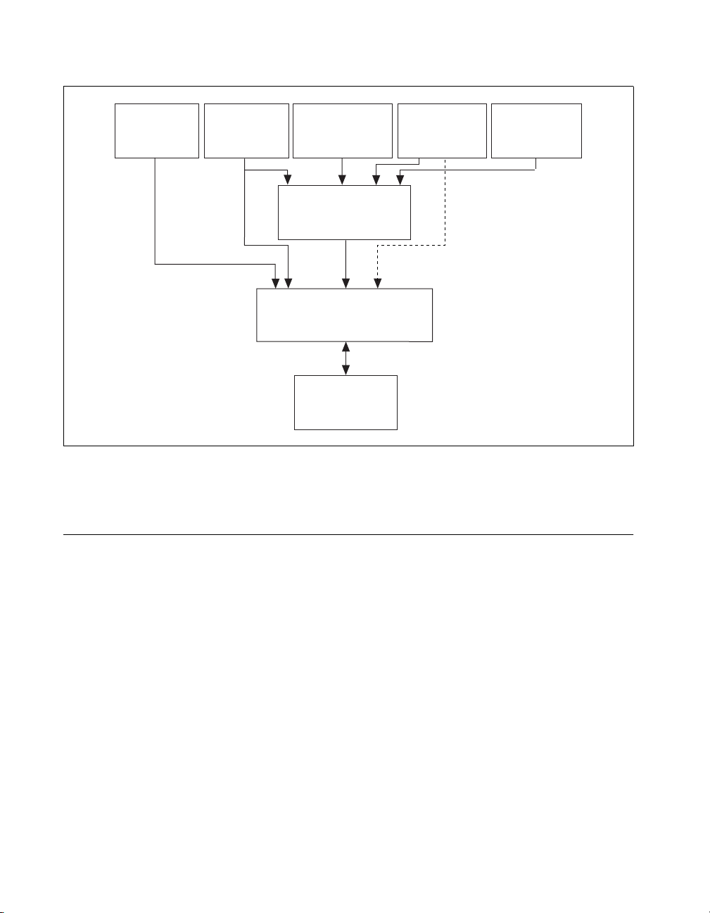
Whether you are using the NI435X instrument driver,
VirtualBench-Logger, LabVIEW, or LabWindows/CVI, your
application uses the NI-DAQ driver software, as illustrated in
Figure 1-1.
Chapter 1 Introduction
©
National Instruments Corporation 1-5 NI 4350 User Manual
Page 16
Chapter 1 Introduction
VirtualBench
(Win95/NT) (Win95/NT)
LabVIEW LabWindows/CVIC/C++
DAQ VI
Library
Figure 1-1. The Relationship between the Programming Environment,
Optional Equipment
(Win95/NT) (Win95/NT)
NI 435x Instrument
Driver API
(Win95/NT)
NI-DAQ Driver Software
PCMCIA, ISA (Win95/NT)
ISA, USB (Win95)
NI 4350
NI-DAQ and Your Hardware
Visual Basic
National Instruments offers a variety of products to use with your
NI 4350, including cables, connector blocks, terminal blocks and other
accessories, as follows:
• Cables and adapters with thermocouple miniconnectors
• Connector blocks including isothermal connector blocks
• Cables and cable accessories, shielded and ribbon
For more specific information about these products, refer to your
National Instruments catalogue or web site or call the office
nearest you.
NI 4350 User Manual 1-6
©
National Instruments Corporation
Page 17

Installation and
Chapter
Configuration
This chapter describes how to install and configure your NI 4350
instrument.
Software Installation
Install your software before you install your NI 4350 instrument. Refer
to the appropriate release notes for specific instructions on the software
installation sequence.
If you are using LabVIEW, LabWindows/CVI, or VirtualBench, refer
to the release notes for your software. After you have installed your
software, refer to the NI-DAQ release notes and follow the instructions
given there for your operating system and your software.
If you are using programming languages such as Visual Basic, C, or
C++ with NI-DAQ, follow the NI-DAQ instructions for installing third
party compilers.
After you have installed your software, you are ready to install your
hardware. Follow the appropriate instructions for your instrument.
2
Hardware Installation
♦ NI 4350 (PCMCIA)
You can install the NI 4350 (PCMCIA) in any available Type II
PCMCIA slot in your computer. Windows 95 or higher includes the
Plug and Play services your operating system will use. Windows NT 4.0
or higher includes the drivers needed to use PCMCIA cards.
The operating system configures the NI 4350 (PCMCIA) and
automatically assigns the base address and the interrupt level. Before
installing your NI 4350 (PCMCIA), consult your computer user manual
or technical reference manual for specific instructions and warnings.
©
National Instruments Corporation 2-1 NI 4350 User Manual
Page 18

Chapter 2 Installation and Configuration
Use the following general instructions to install your NI4350
(PCMCIA):
1. Write down your NI4350 (PCMCIA) serial number on the NI 4 350
Hardware and Software ConfigurationForm in AppendixC.
2. Turn off your computer. If your computer and operating system
support hot insertion, you can insert or remove the NI4350
(PCMCIA) at any time, whether the computer is powered on or off.
3. Remove the PCMCIA slot cover on your computer.
4. Insert the 68-pin I/O connector of the NI4350(PCMCIA) into the
PCMCIA slot until the connector is firmly seated. Notice that the
NI4350(PCMCIA) connectors are keyed so that you can insert it
in only one way.
5. Run the NI-DAQ Configuration Utility to make sure that the
NI4350(PCMCIA) is configured.
6. Configure your accessory using the NI-DAQ Configuration Uti lity.
Your NI4350(PCMCIA) is now installed.
♦ NI 4350 (ISA)
You can install the NI4350(ISA) in any available ISA, AT, or XT slot
in your computer. However, for best noise performance, leave as much
room as possible between the NI4350(ISA) and other hardware.
Before installing your NI4350(ISA), consult your computer user
manual or technical reference manual for specific instructions and
warnings. Use the following general instructions to install your
NI4350(ISA):
1. Write down your NI4350(ISA) serial number on the NI 4350
Hardware and Software ConfigurationForm in AppendixC.
2. Turn off and unplug your computer.
3. Remove the top cover or access port to the I/O channel.
4. Remove the expansion slot cover on the back panel of the
computer.
Caution: The NI4350(ISA) is ESD/contamination sensitive. Handle the board
!
using the metal bracket or edges.
5. Insert the NI4350(ISA) in a 16-bit or 8-bit ISA slot. Although it
may fit tightly, do not force the instrument into place.
NI 4350 User Manual 2-2
©
National Instruments Corporation
Page 19

Chapter 2 Installation and Configuration
6. Screw the mounting bracket of the NI 4350 (ISA) to the back panel
rail of the computer.
7. Replace the cover.
8. Plug in and turn on your computer.
9. Run the NI-DAQ Configuration Utility to make sure that your
NI 4350 (ISA) is configured.
10. Configure your accessory using the NI-DAQ Configuration Utility.
Your NI 4350 (ISA) is now installed.
♦ NI 4350 (USB)
You can connect your NI 4350 (USB) to any available USB connector,
which supports high power, bus-powered peripheral devices. The
following are general installation instructions, but consult your PC user
manual or technical reference manual for specific instructions and
warnings:
1. Connect the USB cable from the computer port or from any other
hub to the port on the NI 4350 (USB).
2. Your computer should detect the NI 4350 (USB) immediately.
When the computer recognizes the NI 4350 (USB), the LED on the
front panel blinks or lights up, depending on the status of your
device.
If the LED comes on after the NI 4350 (USB) is connected to the host,
it is functioning properly. If the LED remains off or blinks, refer to
Table 2-1.
The LED blinks on and off for one second each for as many times as
necessary, then waits three seconds before repeating the cycle.
©
National Instruments Corporation 2-3 NI 4350 User Manual
Page 20

Chapter 2 Installation and Configuration
Table 2-1.
LED Patterns for the NI 4350 (USB) States
LED NI 4350 (USB) State Description
On Configured state Your NI 4350 (USB) is
configured.
Off Off or in the low-power,
suspend mode
Your NI 4350 (USB) is turned
off or in the low-power,
suspend mode.
1 blink Attached state Your NI 4350 (USB) is
recognized but not configured.
2 blinks Addressed state This pattern is displayed if the
host computer detects your
NI 4350 (USB) but cannot
configure it because NI-DAQ is
not properly installed or there
are no system resources
available. Check your software
installation.
3 blinks Power supply failure This pattern is displayed if the
internal power supply shuts
down. Refer to the Power
Considerations for the
NI 4350 (USB) section for more
information.
4 blinks General error state If this pattern is displayed,
Configuration
Your NI 4350 is a completely software-configurable, Plug and Play
instrument. The Plug and Play services query the instrument and
allocate the required resources. Then the operating system enables the
instrument for operation.
NI 4350 User Manual 2-4
contact National Instruments.
©
National Instruments Corporation
Page 21

Chapter 2 Installation and Configuration
Power Considerations for the NI 4350 (USB)
The NI 4350 (USB) is designed to remain powered only when the USB
cable connects it to the host PC and the PC is powered.
The NI 4350 (USB) is designed to run in a stand-alone mode, drawing
power only from the USB cable. There are circumstances when the
NI 4350 (USB) may require more power than the USB power supply
can safely deliver, so if the NI 4350 (USB) tries to draw more than the
allowed current from the USB power supply, internal protection
circuitry will turn off most of the circuitry in the NI 4350 (USB) to
protect the USB supply. This over-current condition makes the LED
blink in the power supply overload pattern described in Table 2-1.
Note: When the NI 4350 (USB) turns off, any data acquisition in progress will be
aborted and the data will be lost.
The host computer has the ability to go into a power-saving suspend
mode and, during this time, the NI 4350 (USB) can go either into a
low-power mode also or remain in a fully powered, static state. This
low-power mode is important if you are using a laptop or if power
consumption is a concern.
In the powered, static state of the NI 4350 (USB), all digital outputs will
be static at a fixed voltage.
Note: Refer to the NI-DAQ function, Set_DAQ_Device_Info, in the NI-DAQ
documentation or to the Set DAQ Device Information.vi in the LabVIEW
documentation to change the settings that determine the behavior of the
NI 4350 (USB) during the suspend state. The default setting is to remain
fully powered.
©
National Instruments Corporation 2-5 NI 4350 User Manual
Page 22

Chapter
NI 4350 Operation
This chapter describes how to use your NI 4350 instrument and includ es
operation tips on taking measurements with temperature sensors such as
thermocouples, RTDs, and thermistors, as well as measuring voltages
and resistances.
Warming up Your NI 4350 Instrument
To minimize the effects of thermal drift and to ensure the specified
accuracy, allow the NI 4350 instrument to warm up for at least
10 minutes after power-up before taking measurements. To maximize
the relative accuracy of measurements, take all measurements after your
NI 4350 instrument warms up for about 30 minutes.
Choosing a Measurement Mode
Each analog input channel can be configured in two possible
measurement modes — the volts mode or the 4-wire ohms mode. Use the
volts mode for thermocouple and voltage measurements and the 4-wire
ohms mode for RTD, thermistor, and resistance measurements using the
built-in current source to provide excitation for your resistive sensors.
In the 4-wire ohms mode, the software will return the resistance value
by dividing the voltage measured by the value of the current source
stored onboard.
3
Note:
VirtualBench, the NI435X instrument driver, and the DAQ Channel
Wizard select the measurement mode auto maticall y, depending on the
sensor type you specify.
Choosing a Range
The volts mode has six bipolar input ranges: ±625 mV, ±1.25 V,
±2.5 V, ±3.75 V, ±7.5 V, and ±15 V.
©
National Instruments Corporation 3-1 NI 4350 User Manual
Page 23
Chapter 3 NI 4350 Operation
The 4-wire ohms mode has six corresponding input ranges when used
with the built-in 25 µΑ current source: 25 kΩ, 50 kΩ, 100 kΩ, 150 kΩ,
300 kΩ, and 600 kΩ. Choose the smallest range for the best
measurement results.
Note: With VirtualBench, the NI435X instrument driver, or the DAQ Channel
Wizard, you can specify the range based on your sensor type in engineering
units appropriate to the sensor.
Choosing a Reading Rate
The reading rate is the rate at which your NI 4350 takes a new
measurement. This rate has a direct relationship with the digital filter
built into the ADC used in the NI 4350.
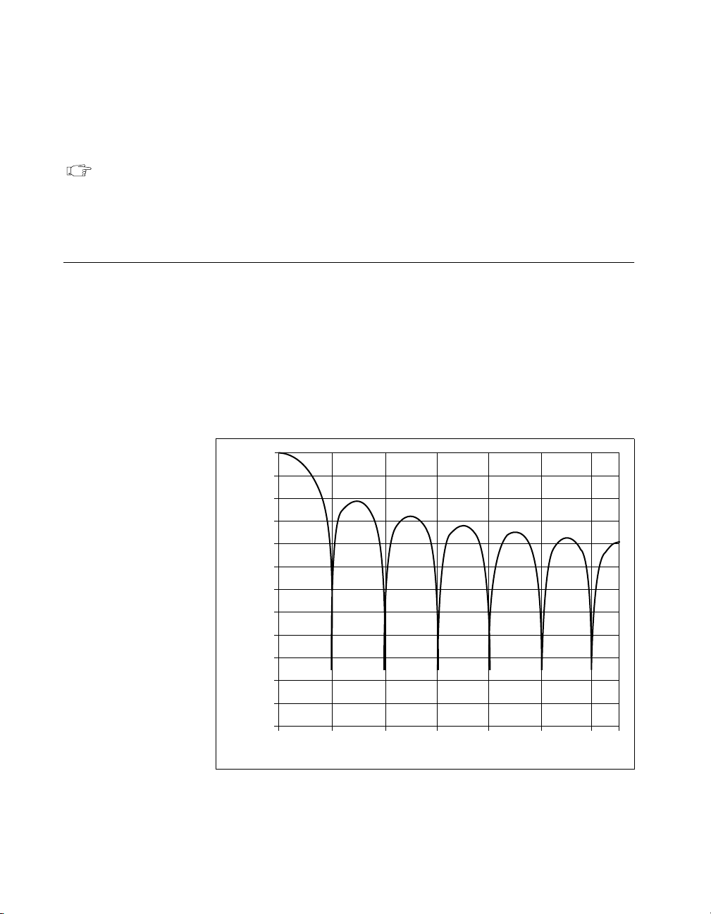
The digital filter has the characteristics shown in Figure 3-1. You can
set the frequency of the first notch of this filter to 10 Hz, 50 Hz, or
60 Hz. Setting the notch filter at one of these frequencies rejects any
noise at that frequency as well as at all its multiples.
0
–20
–40
–60
–80
–100
–120
Gain (dB)
–140
–160
–180
–200
–220
–240
0102030405060
Figure 3-1.
NI 4350 User Manual 3-2
Digital Filter Characteristics for 10 Hz Setting
Frequency (Hz)
©
National Instruments Corporation
Page 24

Chapter 3 NI 4350 Operation
In single-channel measurements, the reading rate is the same as the
notch filter frequency — 10, 50, or 60 readings/s. In multiple-channel
measurements, the reading rates adjust to allow the analog and digital
filters to settle to the specified accuracy.
Note: To determine the reading rate per channel when scanning multiple
channels, divide the multiple-channel measurement reading rate by the
number of channels in the scan.
In certain applications, such as resistance measurements above 25 kΩ
or voltage measurements with more than 25 kΩ of source resistance,
you should measure the same channel for up to 1 s, then switch to
another channel to achieve the specified accuracy.
To optimize measurement accuracy and minimize the noise level,
choose the 10 Hz notch filter setting.
In practice, most of the noise encountered in measurements occurs
at harmonics (multiples) of the local power line frequency (PLF).
Table 3-1 shows which programming settings to use to reject harmonics
of particular frequencies.
Table 3-1. Filtering and Sample Rates
Harmonics of
NI435X Instrument Driver
Equivalent
LabVIEW
Notch Filter
Frequency
Setting (Hz)
10 50
50 50 fast 1
60 60 fast 1 60 60 60 9.7 2.1‡
*Number of power-line cycles used for filtering
†Power line frequency
‡For resistance ranges of 50 kΩ and higher
©
National Instruments Corporation 3-3 NI 4350 User Manual
VirtualBench-Logger
PLF† (Hz) Reading Rate PLC*
slow 5
or
60
Filter Setting
PLF†
(Hz)
6
40
400
8
400
50
60
50
Noise
Frequencies
Rejected (Hz)
10, 50, 60,
and 400
50 and 400 50 8.8 2.1‡
Single-Channel
Measurement
Reading Rate
(readings/s)
10 2.8 1.4‡
Multiple-Channel
Measurement
Reading Rate
(readings/s)
Page 25

Chapter 3 NI 4350 Operation
Knowing Your Signal Source
For accurate measurements, you must determine whether your signal
source is floating or ground-referenced.
Floating Signal Source
A floating signal source is one that is not connected in any way to
the building ground system but has an isolated ground-reference
point. Examples of floating signal sources are thermocouples with
ungrounded junctions and outputs of transformers, batteries,
battery-powered devices, optical isolators, and isolation amplifiers.
Ground-Referenced Signal Source
A ground-referenced signal source is one that is connected in some way
to the building system ground and is, therefore, already connected to a
common ground point with respect to the NI 4350 instrument, assuming
that the computer is plugged into the same power system. Examples of
ground-referenced signal sources are thermocouples with grounded or
exposed junctions connected to grounded test points and outputs of
plug-in devices with nonisolated outputs, voltage across RTDs,
thermistors, or resistors you may be measuring using the built-in current
source of the NI 4350.
Using Programmable Ground-Referencing
Your NI 4350 instrument has software-programmable
ground-referencing on every channel, which you can use to
ground-reference a floating signal source. This connects CH- to ground
through a 10 MΩ resistor and provides a ground-reference for your
floating signal source. Even if your signal source is ground-r eferenced,
this resistance minimizes the effects of ground-loops, as long as the
source impedance and the lead wire resistance is less than 100 Ω. Thus,
you can take accurate measurements even if you are uncertain whether
your signal source is floating or ground-referenced.
Because you can set ground-referencing on a channel-by-channel basis,
you can have ground-referenced signal sources connected to some
channels and floating signal sources connected to other channels in the
same measurement setup. Table 3-2 summarizes the settings to use for
ground-referencing.
©
NI 4350 User Manual 3-4
National Instruments Corporation
Page 26

Chapter 3 NI 4350 Operation
Table 3-2.
Signal
Source
Floating On
Ground-referenced Off
Note: The default setting for programmable ground referencing is on in volts
measurement mode and off in 4-wire ohms mode.
Using Programmable Ground-Referencing
Programmable
Ground-Referencing
Using Programmable Open-Thermocouple Detection
The NI 4350 instruments have software-programmable,
open-thermocouple detection on every channel, which you can use
to detect an open or broken thermocouple. This feature connects
CH+ to +2.5 V through a 10 MΩ resistor. This resistor acts as a pull-up
resistor and, consequently, the voltage between CH+ and CH– rises
rapidly above 100 mV if your thermocouple breaks open. All
thermocouples functioning under normal conditions generate a voltage
of less than 100 mV, even at very high temperatures, which makes this
conclusion possible. You can detect this voltage level in software and
conclude that your thermocouple is open.
To understa nd how setting o pen-thermocou ple detection affects
the accuracy of measurements, refer to the progra mmable
open-thermocouple detection section later in this chapter. You can set
open-thermocouple detection on a channel-by-channel basis. Table 3-3
summarizes the settings you should use for open-thermocouple
detection.
©
National Instruments Corporation 3-5 NI 4350 User Manual
Page 27

Chapter 3 NI 4350 Operation
Table 3-3.
Using Programmable, Open-Thermocouple Detection
Programmable
Signal
Open-Thermocouple
Source
Thermocouples On or Off
Voltage signal sources other than
thermocouples
RTDs, thermistors, and resistors connected
to the built-in current source
Note: The default setting for programmable open-thermocouple detection in volts
and 4-wire ohms measurement modes is off.
Measuring Temperature with Thermocouples
The thermocouple is the most popular transducer for measuring
temperature. Because the thermocouple is inexpensive, rugged, and can
operate over a very wide range of temperatures, it is a versatile and
useful sensor.
Detection
Off
Off
A thermocouple operates on the principle that the junction of two
dissimilar metals generates a voltage that varies with temperature, or
thermal EMF. However, just measuring this voltage is not sufficient
because connecting the thermocouple to the NI 4350 instrument
accessory creates the reference junction or cold-junction, shown in
Figure 3-2. These additional junctions act as thermocouples,
themselves, and produce their own voltages. Thus, the final measured
voltage, V
, includes both the thermocouple voltage, V
measured
and the cold-junction voltage, V
compensating for these unwanted cold-junction voltages is called
cold-junction compensation.
NI 4350 User Manual 3-6
cold-junction
. The method of
thermocouple
©
National Instruments Corporation
,
Page 28

V
thermocouple
Chapter 3 NI 4350 Operation
V
2
+
+
–
–
+
–
V
1
+
V
measured
–
V
measured = Vthermocouple +V1
– V2 where V1 – V2 = V
cold-junction
Figure 3-2. Effect of the Cold-Junction
With the NI 4350 instruments, you can perform cold-junction
compensation in software. To do this, you can use the thermistor
temperature sensor on the NI 4350 accessory to measure the ambient
temperature at the cold-junction and compute the appropriate
compensation for the unwanted thermoelectric voltages using software.
You have several options for performing cold-junction compensation,
as shown below.
• If you are using the NI435X instrument driver, LabVIEW,
LabWindows/CVI, VirtualBench, or the DAQ Channel Wizard,
your software will automatically perform cold-junction
compensation on all channels configured as thermocouple
channels.
• If you are using LabVIEW and are not using the instrument driver
or the DAQ Channel Wizard, your software includes examples that
perform these temperature-to-voltage and voltage-to-temperature
conversions for the cold-junction thermistor and various types of
thermocouples based on the National Institute of Standards and
Technology (NIST) standard reference tables. These examples are
located in the DAQ analog input example library and have 4350 in
their title.
• If yo u are not using either of the previous so ftware options, follow
the steps below to perform cold-junction compensation:
1. Measure the resistance of the thermistor cold-junction sensor,
R
thermistor cold-junction
temperature, T
, and compute the cold-junction
cold-junction
, using the thermistor
resistance-temperature conversion formula.
2. From this temperature of the cold-junction, T
compute the equivalent thermocouple voltage, V
cold-junction
,
cold-junction
, for
this junction using a standard thermocouple conversion
formula.
©
National Instruments Corporation 3-7 NI 4350 User Manual
Page 29

Chapter 3 NI 4350 Operation
3. Measure the voltage, V
voltage, V
4. Convert the resulting voltage to temperature using a standard
thermocouple conversion formula.
Connecting Your Thermocouple
The NI 4350 accessories—the PSH32-TC6 and the CB-27T for the
NI 4350 (PCMCIA), and the TC-2190 and the TBX-68T for the
NI 4350 (ISA) and the NI 4350 (USB)—are designed to be used with
thermocouples. Consult your accessory installation guide for
instructions on how to connect your thermocouples. To make accurate
measurements, make sure that the common-mode voltage of the
thermocouple is within the input common mode limits of the selected
input range.
The NI 4350 instrument analog inputs are protected against damage
from voltages within ±42 VDC in all ranges when powered up and
±17 VDC when the NI 4350 instrument is powered down. You should
never apply voltages above these levels to the inputs.
Caution: To prevent possible safety hazards, the maximum voltage between any of
!
the analog inputs and the computer ground should never exceed ±42 VDC
when the NI 4350 instrument is powered up and ±17 VDC when the
NI 4350 instrument is powered down.
cold-junction
, and add the cold-junction
measured
, computed in step 2.
Input Ranges
Choose the ±625 mV range in volts mode when you are measuring
thermocouples. You can measure both the thermocouples and the
thermistor cold-junction sensor on the NI 4350 accessory in the same
scan by choosing the 25 kΩ range for measuring the thermistor. This
range offers the best resolution, noise rejection, and accuracy.
Optimizing Measurements
To make accurate thermocouple measurements, set the onboard
programmable ground-referencing and open-thermocouple detection
appropriately. Also consider problems associated with AC noise
effects, thermal EMF, and other errors as discussed in the following
sections.
NI 4350 User Manual 3-8
©
National Instruments Corporation
Page 30

Chapter 3 NI 4350 Operation
Auto-Zero
Auto-zero is a method that instruments use to remove any offset errors
in the measurement. Analog channel 1 (CH1) on the PSH32-TC6,
CB-27T, TC-2190, and TBX-68T is dedicated for auto-zero. CH1+ is
connected to CH1– on these accessories. You can measure the voltage
offset on this auto-zero channel and subtract it from the voltage
measurements on other channels. This way, you can compensate for any
residual offset error the NI 4350 instrument may have. This is
especially useful when your NI 4350 instrument is operating at an
ambient temperature other than that of calibration (23° C typical).
Note: When using the VirtualBench-L ogger alo ng with NI 4350 accessories—
PSH32-TC6, CB-27T, TC-2190, or TBX-68T—auto-zeroing is
implemented automatically.
Programmable Ground-Referencing
If you determine that your thermocouple is ground-referenced, switch
off ground-referencing on that channel.
If you determine that your thermocouple is floating, switch on
ground-referencing on that channel. Otherwise, the thermocouple
inputs may float out of the input common-mode limits of the NI 4350
instrument.
When you use the PSH32-TC6, CB-27T, TC-2190, and TBX-68T
accessories, always switch on ground-referencing on CH1. Doing this
ground-references the auto-zero channel.
On all the NI 4350 instrument accessories used with thermocouples,
analog channel CH0 is dedicated to the thermistor cold-junction sensor.
The built-in current source return terminal IEX- is tied to –2.5 V
through a resistor. This references any resistor excited by the current
source to ground. Since this current source excites the cold-junction
thermistor, CH0 is automatically ground-referenced. Therefore, when
measuring the voltage across this thermistor, always switch off
programmable ground-referencing on CH0. Otherwise, the leakage
current flowing into the thermistor may cause erroneous measurements
in all the channels that use the current source.
Note: When using VirtualBench-Logger, the DAQ Channel Wizard, or the
NI435X Instrument Driver, the ground-referencing switch on the
cold-junction sensor channel and auto-zero channel is set appropriately,
automatically.
©
National Instruments Corporation 3-9 NI 4350 User Manual
Page 31

Chapter 3 NI 4350 Operation
Programmable Open-Thermocouple Detection
To detect open or broken thermocouples, switch on open-thermocouple
detection on that channel. Then, if the thermocouple breaks, the voltage
on that channel will rise rapidly above 100mV, at whi ch po int yo u can
conclude that the thermocouple is open.
Notice that when open-thermocouple detection is on and the floating
thermocouple is not broken, a very small amount of current is
injectedinto the thermocouple. It is approximately 125 nA when
ground-referencing is also on. If the thermocouple is very long, this
injected current can cause an error voltage to develop in the lead
resistance of the thermocouple that is indistinguishable from the
thermocouple voltage you are measuring. You can estimate this error
voltage with the following formula:
error voltage = resistance of the thermocouple • 125 nA
For example, if you use a 100 ft long, 24 AWG J-type thermocouple
with a resistance of 0.878 Ω per double foot, the error voltage generated
is approximately 11 µV, which corresponds to about 0.2 ° C. If this error
is too large for your measurement, you can reduce the error by reducing
the thermocouple resistance. Do this by reducing the length of the
thermocouple or lowering the AWG of the wire (use a wire of larger
diameter). Alternatively, you can switch off the open-thermocouple
detection to eliminate the c urrent injecte d into th e thermoc ouple.
AC Noise Effects
Your NI 4350 instrument rejects AC voltages as specified in NMR in
AppendixA, Specifications. However, if the amplitudes of the AC
voltages are large compared to the DC voltages, or if the peak value
(AC + DC) of the measured voltage is outside the input range, the
NI4350 instrument may exhibit additional errors. To minimize these
errors, keep the thermocouples and the NI 4350 instrument and its
accessory away from strong AC magnetic sources and minimize the
area of the loop formed by the thermocouple wires connected to the
accessory. Choose the notch filter frequency of 10Hz for the best AC
noise rejection. If the peak value of the measured voltage is likely to
exceed the selected input range, select the next higher input range.
Thermal EMF
When using thermocouples, any thermal EMFs other than those at the
hot-junction (where the thermocouple measures the test point
NI 4350 User Manual 3-10
©
National Instruments Corporation
Page 32

temperature) and at the cold-junction on the accessory will introduce
error.
To minimize thermal EMFs, use wires of the same thermocouple
type when extending the length of the thermocouple. Also, minimize
temperature gradients in the space enclosing the thermocouple, the
NI 4350 instrument, and its accessories.
Measuring DC Voltage
Connecting Your DC Voltage Signal
The NI 4350 accessories—the CB-27T and CB-27 for the NI 4350
(PCMCIA), and the TBX-68T and TBX-68 for the NI 4350 (ISA) and
the NI 4350 (USB)—are designed to be used with any DC voltage
signal. Consult your accessory installation guide for instructions on
how to connect your voltage signals.
The NI 4350 analog inputs are protected against damage from voltages
within ±42 VDC in all ranges when powered up and ±17 VDC when the
NI 4350 instrument is powered down. You should never apply voltages
above these levels to the inputs.
Chapter 3 NI 4350 Operation
Caution: To prevent possible safety hazards, the maximum voltage between any of
!
the analog inputs and the computer ground should never exceed ±42 VDC
when the NI 4350 instrument is powered up and ±17 VDC when the
NI 4350 instrument is powered down.
Input Ranges
Your NI 4350 instrument has six bipolar input ranges available for
measuring DC voltage. These ranges are ±625 mV, ±1.25 V, ±2.5 V,
±3.75 V, ±7.5 V, and ±15 V. The NI 4350 instrument can measure DC
voltage to the specified accuracy as long as the voltage is within the
selected input range. To get the best resolution, noise rejection, and
accuracy, choose the smallest possible range. Make sure that each
signal input to CH+ and CH– is within the input common mode limits
of this input range. The input common mode limits are ±2.5 V and
±15 V for the lower three and higher three input ranges, respectively.
©
National Instruments Corporation 3-11 NI 4350 User Manual
Page 33

Chapter 3 NI 4350 Operation
Optimizing Measurements
To make accurate voltage measurements, program the onboard
ground-referencing and open-thermocouple detection appropriately.
Also consider problems associated with AC noise effects, thermal
EMFs, and other errors as discussed in the following sections.
Auto-Zero
Auto-zero is a method that instruments use to remove offset errors
in the measurement. Analog channel 1 (CH1) on the CB-27T and
TBX-68T is dedicated for auto-zero. CH1+ is connected to CH1– on
these accessories. When using a CB-27 or TBX-68 accessory for RTDs,
connect CH– to CH+ (any channel) to make that channel useful for
auto-zero. You can measure the voltage offset on this auto-zero channel
and subtract it from the voltage measurements on other channels. This
way, you can compensate for any residual offset error the NI 4350
instrument may have. This is especially useful when the NI 4350
instrument is operating at an ambient temperature other than that of
calibration (23° C typical).
Note: When using the VirtualBench-Logger along with NI 4350 accessor ies—
PSH32-TC6, CB-27T, TC-2190, or TBX-68T—auto-zeroing is
implemented automatically.
Programmable Ground-Referencing
If you determine that your signal source is ground-referenced, switch
off ground-referencing on that channel.
If you determine that your signal source is floating, switch on
ground-referencing on that channel. Otherwise, the inputs may float
out of the input common mode limits of the NI 4350 instrument.
When you use the CB-27T and TBX-68T accessories, always switch on
ground-referencing on CH1. Doing this ground-references the
auto-zero channel.
Note: When using the VirtualBench-Logger, or NI435X Instrument Driver, or
the DAQ Channel Wizard, along with the NI 4350 accessories—
PSH32-TC6, CB-27T, TC-2190, or TBX-68T— the ground-referencing
switch on the auto-zero channel is set appropriately, automatically.
NI 4350 User Manual 3-12
©
National Instruments Corporation
Page 34

Chapter 3 NI 4350 Operation
Programmable Open-Thermocouple Detection
When you measure voltage signals other than thermocouples, always
switch off the onboard, open-thermocouple detectio n.
Source Impedance
For best results, maintain the source impedance and the lead wire
resistance of your signal at less than 100Ω. If either of these is greater
than 25kΩ, you should measure the same channel for up to 1 s, then
switch to another channel to achieve the specified accuracy.
AC Noise Effects
Your NI4350 instrument rejects AC voltages as specified in NMR in
AppendixA, Specifications. However, if the amplitudes of the AC
voltages are large compared to the DC voltages, or if the peak value
(AC + DC) of the measured voltage is outside the input range, the
NI4350 instrument may exhibit additional errors. To minimize these
errors, keep the signal source and the NI4350 instrument and its
accessories away from strong AC magnetic sources and minimize the
area of the loop formed by the wires that connect the signal source
withthe accessories. Choosing the notch filter frequency of 10Hz will
provide you with the best AC noise rejection. If the peak value of the
measured voltage is likely to exceed the selected input range, select the
next higher input range.
Thermal EMF
Thermoelectric potentials or thermal EMFs are voltages generated at
the junctions of dissimilar metals and are functions of temperature.
Thermal EMFs in the source generating the signal can introduce errors
in measurements that change with variations in temperature.
To minimize thermal EMFs, use copper wires to connect the signal to
the NI4350 instrument accessory. Avoid using dissimilar metal wires
in connections. Also, minimize temperature gradients in the space
enclosing the signal source, the NI4350 instrument, and its accessories.
©
National Instruments Corporation 3-13 NI 4350 User Manual
Page 35

Chapter 3 NI 4350 Operation
Measuring Temperature with RTDs and Thermistors
and Measuring Resistance
RTDs and thermistors are essentially resistors whose resistance varies
with temperature. Therefore, measurement techniques for RTDs,
thermistors, and resistors are quite similar. All techniques involve
exciting the resistor with a current or a voltage source and measuring
the resulting voltage or current, respectively, developed in the resistor.
With the NI 4350, you can excite your resistor with the built-in
precision current source and measure the resulting voltage. When using
LabVIEW, set the measurements mode to 4-wire ohms.When using the
NI435X instrument driver, set the measurement mode to Resistance.
These modes will return the measurements in units of resistance (ohms)
by dividing the measured voltage with the calibrated value of the
precision current source stored onboard. The follo wing sections explain
the various measurement techniques in detail.
Introduction to RTDs
An RTD is a temperature-sensing device whose resistance increases
with temperature. An RTD consists of a wire coil or deposited film
of pure metal. RTDs can be made of different metals and can have
different resistances, but the most popular RTD is made of platinum
and has a nominal resistance of 100 Ω at 0° C.
RTDs are known for their excellent accuracy over a wide temperature
range. Some RTDs have accuracy as high as 0.01 Ω (0.026° C) at 0° C.
RTDs are also extremely stable devices. Common industrial RTDs drift
less than 0.1° C/year and some models are stable to within
0.0025° C/year.
RTDs can be difficult to measure because they have relatively low
resistance (100 Ω) that changes only slightly with temperature
(less than 0.4 Ω/° C). To accurately measure these small changes in
resistance, you may need to use special configurations that minimize
errors from lead wire resistance.
Relationship of Resistance and Temperature
in RTDs
Compared to other temperature devices, the output of an RTD
is relatively linea r with respect to temperature. The temperature
NI 4350 User Manual 3-14
©
National Instruments Corporation
Page 36

Chapter 3 NI 4350 Operation
coefficient, called alpha (α) differs between RTD curves. Although
various manufacturers may specify α differently, α is most commonly
defined as the change in RTD resistance from 0° to 100° C, divided by
the resistance at 0° C, divided by 100° C:
α (Ω/Ω/° C) = [(R
where R
is the resistance of the RTD at 100° C, and R0 is the
100
- R0)/R0]/100° C
100
resistance of the RTD at 0° C.
For example, a 100 Ω platinum RTD with α = 0.00385 will measure
138.5 Ω at 100° C. Figure 3-3 shows a typical resistance-temperature
curve for a 100 Ω platinum RTD.
1 k
100
Resistance (Ω)
10
0
–200
–150
–100
–50
50
100
Temperature (˚C)
150
Figure 3-3. Resistance-Temperature Curve for a 100 Ω
(PT 100 Ω)
200
RTD
250
300
350
Platinum RTD
400
Although the resistance-temperature curve is relatively linear,
converting measured resistance to temperature accurately requires
curve fitting. The Callendar-Van Dusen equation is commonly used to
approximate the RTD curve:
R
= R0 • [1 + A • t + B • t2 + C • (t – 100) • t3]
RTD
where R
is the resistance of the RTD at temperature T
RTD
, R0 is the
RTD
resistance of the RTD in Ω at 0° C, A, B, and C are the
Callendar-Van Dusen coefficients shown in Table 3-4, and T
RTD
is the
temperature in ° C. For temperatures above 0° C, coefficient C equals 0.
©
National Instruments Corporation 3-15 NI 4350 User Manual
Page 37

Chapter 3 NI 4350 Operation
Therefore, for temperatures above 0° C, this equation reduces to a
quadratic:
R
RTD
2
------------ -1–
R
RTD
-------------------------------------------------------------------=
AA
T
0
2
++
R
RTD
4
------------ -1–
•
B
R
0
Most platinum RTD curves follow one of three standardized curves:
the DIN 43760 standard (α = 0.00385), the U.S. Industrial or American
standard (α = 0.003911), or the International Temperature Scale
(ITS-90) that is used with wire-wound RTDs ( α = 0.003925). Table 3-4
lists the Callendar-Van Dusen coefficients for each of these three
platinum RTD curves.
Table 3-4.
Callendar-Van Dusen Coefficients Corresponding to Common RTDs
Temperature
Standard
DIN 43 760 0.003850 3.9080 • 10
American 0.003911 3.9692 • 10
ITS-90 0.003925 3.9848 • 10
* For temperatures below 0° C only; C = 0.0 for temperatures above 0° C.
Coefficient α
A B C*
–3
–3
–3
Note: Software packages, such as VirtualBench, NI435X instrument driver, DAQ
Channel Wizard, LabVIEW, and LabWindows/CVI include routines that
perform these conversions for different types of RTDs based on the various
commonly used standards.
Connecting Your RTD
Because the RTD is a resistive device, you must pass current through
the device and measure the resulting voltage. However, any resistance
in the lead wires that connect your measurement system to the RTD will
add errors to your readings. For example, consider a two-wire RTD
element connected to the NI 4350 instrument accessory that also
supplies a constant current source IEX to excite the RTD. As shown in
Figure 3-4, the voltage drop across the lead resistance R
measured voltage.
–5.8019 • 10
–5.8495 • 10
–5.870 • 10
–7
–7
–7
–4.2735 • 10
–4.2325 • 10
–4.0000 • 10
, adds to the
L
–12
–12
–12
NI 4350 User Manual 3-16
©
National Instruments Corporation
Page 38

Chapter 3 NI 4350 Operation
IEX+
CH+
CH–
IEX–
RTD
R
L
R
L
Figure 3-4. Two-Wire RTD Measurement
For example, a lead resistance RL of 0.3 Ω in each wire adds a 0.6 Ω
error to the resistance measurement. For a platinum RTD with
α = 0.00385, the resistance equals a 0.6 Ω/(0.385 Ω/° C) = 1.6° C error.
If you are using lead lengths greater than 10 ft., you may need to
compensate for this lead resistance in order to increase accuracy. The
preferred RTD measurement method is to use a four-wire RTD. One
pair of wires carries the current through the RTD; the other pair senses
the voltage across the RTD. Because only negligible current flows
through the sensing wires, the lead resistance error of R
and RL3 is
L2
negligible. Figure 3-5 illustrates this configuration.
R
L1
R
L2
IEX+
CH+
RTD
R
L3
R
L4
CH–
IEX–
Figure 3-5. Four-Wire RTD Measurement
Alternatively, you can use a three-wire RTD instead. Figure 3-6 shows
a the three-wire RTD in a Wheatstone configuration with a current
source. Another variation of the three-wire RTD configuration is shown
in Figure 3-7. In this configuration, the resistance R
of only one lead
L1
adds error to the measurement.
©
National Instruments Corporation 3-17 NI 4350 User Manual
Page 39

Chapter 3 NI 4350 Operation
R
RTD
R
R
L1
R
1
L2
L3
CH+ CH–
R
3
R
2
IEX+
IEX–
Figure 3-6. Three-Wire RTD Measurement with a Wheatstone Bridge
and a Current Source
IEX+
R
L1
RTD
CH+
See Figure 3-10 for an example of how you can use different
transducers connected to analog channels in the same measurement
setup.
Introduction to Thermistors
A thermistor is a piece of semiconductor made from metal oxides,
pressed into a small bead, disk, wafer, or other shape, sintered at high
temperatures, and finally coated with epoxy or glass. The resulting
device exhibits an electrical resistance that varies with temperature.
There are two types of thermistors—negative temperature coefficient
(NTC) thermistors and positive temperature coefficient (PTC)
thermistors. An NTC thermistor is one whose resistance decreases with
increasing temperature. A PTC thermistor is one whose resistance
increases with increasing temperature. NTC thermistors are much more
R
L2
R
L3
CH–
IEX–
Figure 3-7. Three-Wire RTD Measurement
NI 4350 User Manual 3-18
©
National Instruments Corporation
Page 40

Chapter 3 NI 4350 Operation
commonly used than PTC thermistors, especially for temperature
measurement applications.
A main advantage of thermistors for temperature measurement is their
extremely high sensitivity. For example, a 2252 Ω thermistor has a
sensitivity of –100 Ω/° C at room temperature. Higher resistance
thermistors can exhibit temperature coefficients of –10 kΩ/° C or more.
In comparison, a 100 Ω platinum RTD has a sensitivity of only
0.4 Ω/° C. The small size of the thermistor bead also yields a very
fast response to temperature changes.
Another advantage of the thermistor is its relatively high resistance.
Thermistors are available with base resistances (at 25° C) ranging from
hundreds to millions of ohms. This high resistance dimini shes the effect
of inherent resistances in the lead wires, which can cause significant
errors with low resistance devices such as RTDs. For example, while
RTD measurements typically require four-wire or three-wire
connections to reduce errors caused by lead wire resistances, two-wire
connections to thermistors are usually adequate.
The major trade-off for the high resistance and sensitivity of the
thermistor is its highly nonlinear output and relatively limited oper ating
range. Depending on the type of thermistors, upper ranges are typically
limited to around 300° C. Figure 3-8 shows the resistance-temperature
curve for a 5,000 Ω thermistor. The curve of a 100 Ω RTD is also shown
for comparison.
10 M
Resistance (Ω)
1 M
100 k
10 k
1 k
100
10
–200
–150
–100
–50
Thermistor
(5,000 Ω at 25˚ C)
0
50
Temperature (˚C)
100
(PT 100 Ω at 0˚ C)
150
200
RTD
250
300
350
400
Figure 3-8. Resistance-Temperature Curve of a Thermistor
©
National Instruments Corporation 3-19 NI 4350 User Manual
Page 41

Chapter 3 NI 4350 Operation
The thermistor has been used primarily for high-resolution
measurements over limited temperature ranges. Continuous
improvements in thermistor stability, accuracy, and the availability
of interchangeable thermistors have prompted increased usage of
thermistors in all types of industries.
Resistance-Temperature Characteristic of Thermistors
The resistance-temperature behavior of thermistors is highly dependen t
upon the manufacturing process. Therefore, thermistor manufacturers
have not standardized thermistor curves to the extent that thermocouple
or RTD curves have been standardized.
Typically, thermistor manufacturers supply the resistance-versustemperature curves or tables for their particular devices. The thermistor
curve, however, can be approximated relatively accurately with the
Steinhart-Hart equation:
TK()
Where T(K) is the temperature in kelvin, equal to T(° C) + 273.15, and
Rt is the resistance of the thermistor. The coefficients a, b, and c can be
provided by the thermistor manufacturer, or calculated from the
resistance-versus-temperature curve.
Software packages such as LabVIEW and LabWindows/CVI include
routines that perform these conversions for some types of thermistors.
You can also modify these conversion routines for your particular type
of thermistor.
Connecting Your Thermistor
Because the thermistor is a resistive device, you must pass a current
through the thermistor to produce a voltage that can be measur ed by the
NI 4350 instrument. The high resistance and high sensitivity of the
thermistor simplify the necessary measurement circuitry and signal
conditioning. Special three-wire, four-wire, or Wheatstone bridge
connections are not necessary. As shown in Figure 3-9, the measured
voltage Vt will be equal to (Rt • IEX).
----------------------------------------------=
ab+Rtln• cRtln
1
3
NI 4350 User Manual 3-20
©
National Instruments Corporation
Page 42

See Figure3-10 for an example of how you can use different
transducers connected to analog channels in the same measurement
setup.
Connecting Your Resistor
You can use signal connection techniques, described in the sections,
Connecting Your RTD and Connecting Your Thermistor, for any resistor
as well.
The NI4350 accessories—the CB-27T and CB-27 for the NI4350
(PCMCIA), and the TBX-68T and TBX-68 for the NI4350 (ISA) and
the NI4350 (USB)—are designed to be used with RTDs, thermistors,
and resistors. Consult your accessory installation guide for instructions
on how to connect your resistors. Figure3-10 shows an example o f how
to use different transducers connected to analog channels in the same
measurement setup.
Chapter 3 NI 4350 Operation
IEX+
CH+
Rt
CH–
IEX–
Figure 3-9. Thermistor Measurement
©
National Instruments Corporation 3-21 NI 4350 User Manual
Page 43

Chapter 3 NI 4350 Operation
+ R
+ R
cjthermistor
thermistor
Voltage here is
Voltage here is
{–2.5 V + [(20 kΩ
+ R
Voltage here is
{–2.5 V + [(20 kΩ
+ R
Voltage here is
{–2.5 V + [(20 kΩ
Voltage here is
{–2.5 V + [(20 kΩ + R
+ R
rtd
+ R
cjthermistor
+ R
cjthermistor
{–2.5 V + [20 kΩ X 25 µA]}
cjthermistor
) X 25 µA]}
) X 25 µA]}
rtd
) X 25 µA]}
rtd
) X 25 µA]}
Thermistor
Ground-Referenced Thermocouple
Floating Thermocouple
RTD
Auto-Zero
Cold-Junction Thermistor (on Accessory)
IEX–
IEX+
CH5+
CH5–
CH4+
CH4–
CH3+
CH3–
CH2+
Ground-Referencing: Off
Open-Thermocouple
Detection: Off
Ground-Referencing: Off
Open-Thermocouple
Detection: On
Ground-Referencing: On
Open-Thermocouple
Detection: On
Ground-Referencing: Off
Open-Thermocouple
CH2–
CH1+
CH1–
CH0+
Detection: Off
Ground-Referencing: On
Open-Thermocouple
Detection: Off
Ground-Referencing: Off
Open-Thermocouple
CH0–
Detection: Off
Internal to the NI 4350
20 kΩ
–2.5 V
Figure 3-10. Multiple Transducer Connections to Analog Channels in
The NI 4350 instrument analog inputs are protected against damage
from voltages within ±42 VDC in all ranges when powered up and
±17 VDC when powered down. Never apply voltages above these
levels to the inputs.
Caution: To prevent possible safety hazards, the maximum voltage between any of
!
the analog inputs and the computer ground should never exceed ±42 VDC
when the NI 4350 instrument is powered up and ±17 VDC when the
NI 4350 instrument is powered down.
NI 4350 User Manual 3-22
One Measurement Setup
©
National Instruments Corporation
Page 44

Input Ranges
Chapter 3 NI 4350 Operation
The NI 4350 has six ranges for resistance measurements. These ranges
are 25 kΩ, 50 kΩ, 100 kΩ, 150 kΩ, 300 kΩ, and 600 kΩ.These ranges
correspond to the six input ranges available for measuring DC voltages
developed across resistors. These ranges are ±625 mV, ±1.25 V,
±2.5 V, ±3.75 V, ±7.5 V, and ±15 V. To determine the most suitable
input range for your application, estimate th e v oltage develo ped across
the resistor by following the procedure outlined in Figure 3-10. Also
estimate the common-mode voltage at the inputs and verify that the
range you select can handle that common mode voltage. Also estimate
the common-mode voltage at the inputs and verify that the range you
select can handle that common-mode voltage. Choose the 25 kΩ range
in the 4-wire ohms mode when you are measuring RTDs and
thermistors, for best results.
The NI 4350 instrument can measure resistances to its specified
accuracy as long as the voltage across the resistors is within the selected
input range specified above. To get the best resolution, noise rejection
and accuracy, choose the smallest range in which your signals will be
accommodated. Make sure that each signal input to CH+ and CH– is
within the input common mode limits of this input range. The input
common mode limits are ±2.5 V and ±15 V, for the lower three and
higher three input ranges, respectively.
For resistance higher than 25 kΩ, a settling time of over 1 s may be
required when changing channels, to achieve the specified accuracy.
Optimizing Measurements
In addition to the potential problems discussed in the sections on
connecting your RTDs and thermistors, also consider other problems
associated with AC noise effects, thermal EMF, and other errors as
discussed in the following sections.
Auto-Zero
Auto-zero is a method that instruments use to remove any offset errors
in the measurement. Analog channel 1 (CH1) on the PSH32-TC6,
CB-27T, TC-2190, and TBX-68T is dedicated for auto-zero. CH1+ is
connected to CH1– on these accessories. You can measure the voltage
offset on this auto-zero channel and subtract it from the voltage
measurements on other channels. This way, you can compensate for any
residual offset error the NI 4350 instrument may have. This is
©
National Instruments Corporation 3-23 NI 4350 User Manual
Page 45

Chapter 3 NI 4350 Operation
Note: When using VirtualBench-Logger along with NI 4350 accessories—
PSH32-TC6, CB-27T, TC-2190, or TBX-68T—auto-zeroing is
implemented automatically.
especially useful when your NI 4350 instrument is operating at an
ambient temperature other than that of calibration (23°C typical). Use
the 4-wire mode in LabVIEW while reading the offset for resistance
measurements.
Programmable Ground-Referencing
Always switch off ground-referencing on the channel connected to a
resistor excited by the current source. The current source return
terminal IEX– is tied to –2.5V through a resistor. This causes any
resistor excited by the current source to be ground-referenced.
Otherwise, the leakage current flowing into the resistor can cause
erroneous measurement for all channels that use the current source.
Programmable Open-Thermocouple Detection
Always switch off open-thermocouple detection on the channel
connected to a resistor. Otherwise, the leakage current flowing into the
resistor can cause erroneous measurement for all channels that use the
current source.
Connecting to External Circuits
See Figure3-10 for an example of how different transducers connect to
analog channels in the same measurement setup. To measure the value
of a resistor accurately, make sure the resistor is not electrically
connected to any other circuits. Erroneous or misleading readings can
result if the resistor you are measuring is electrically connected to
external circuits that supply voltages or currents or is connected to
external circuits that change the effective resistance of that resistor.
Two-Wire, Three-Wire, and Four-Wire Measurements
The discussion in Connecting Your RTD on whether to use two-wire,
three-wire, or four-wire, earlier in this chapter, applies to any resistance
measurement. Choose the appropriate measurement technique for your
application as shown in Table3-5.
NI 4350 User Manual 3-24
©
National Instruments Corporation
Page 46

Chapter 3 NI 4350 Operation
Table 3-5.
Resistance Being
Measured (Ω)
Guidelines for Resistance Measurement
Measurement
Technique
R ≤ 1 kΩ Four-wire
1 kΩ < R ≤ 10 kΩ Four-wire or three-wire
R > 10 kΩ Four-wire, three-wire, or two-wire
Self-Heating
The current source on the NI 4350 instrument is designed such that any
error resulting from self-heating is negligible in most cases. This
section explains how that occurs.
When current is passed through an RTD or a thermistor (both are
resistive devices), power dissipated is equal to I
resistive devices. This phenomena is called self-heating and is typically
specified by manufacturers in the form of the dissipation constant,
which is the power required to heat the thermistor by 1° C from ambient
temperature and is usually has units of mW/° C. The dissipation
constant depends significantly on how easily heat is transferred away
from the thermistor, so the dissipation constant may be specified for
different media—in still air, water, or oil bath.
2
R, which heats the
Thermistors, with their small size and high resistance, are particularly
prone to these self-heating errors. Typical dissipation constants range
anywhere from less than 0.5 mW/° C for still air to 10 mW/° C or higher
for a thermistor immersed in water. A 5,000 Ω thermistor powered by
a25µA excitation current will dissipate:
2
I
R=(25µA)2• 5,000 Ω =3.1µW.
If this thermistor has a dissipation constant of 10 mW/° C,
the thermistor will self-heat by only 0.003° C. Thus, the small value of
the current source helps you prevent any appreciable error due to
self-heating.
RTDs are inherently immune to this problem of self-heating because
their resistance is relatively small—100 Ω at 0° C, for example. Here ,
also, the amount of self-heating depends significantly on the medium in
which the RTD is immersed. An RTD can self-heat up to 100 times
©
National Instruments Corporation 3-25 NI 4350 User Manual
Page 47

Chapter 3 NI 4350 Operation
higher in still air than in moving water. The self-heating in RTDs due
to the built-in 25µA is negligible.
AC Noise Effects
The NI4350 instruments reject AC noise as specified in NMR
inAppendixA, Specifications. However, if the amplitudes of the AC
noise are large compared to the DC signal, or if the peak value (AC +
DC) of the measured signal is outside the input range, the NI4350
instrument may exhibit additional errors. To minimize these errors,
keep the signal source and the NI4350 instrument and its accessory
away from strong AC magnetic sources and minimize the area of the
loop formed by the wires connecting the signal source with the
accessory. Choosing the notch filter frequency of 10Hz will provide
you with the best AC noise rejection. If the peak value of the measured
voltage is likely to exceed the selected input range, select the next
higher input range.
Thermal EMF
Thermoelectric potentials or thermal EMFs are voltages generated at
the junctions of dissimilar metals and are functions of temperature.
Thermal EMFs in the source generating the signal can introduce errors
in measurements that change with variations in temperature.
To minimize thermal EMFs, use copper wires to connect the signal
tothe NI4350 instrument accessory. Avoid using dissimilar metal
wires inconnections. Also, keep out temperature gradients in the space
enclosing the signal source, the NI4350 instrument and its accessories.
Using the Current Source
The NI4350 features a precision current source, which supplies 25µA
and provides excitation to a total maximum resistance of 600kΩ. This
resistance can be in the form of RTDs, thermistors, or any other resistor.
The calibrated value of the current source is stored on-board. Refer to
the sections Measuring Temperature with RTDs and Thermistors and
Measuring Resistance for details on how to use this current source.
NI 4350 User Manual 3-26
©
National Instruments Corporation
Page 48

Using Digital Inputs and Outputs
The NI 4350 features TTL-compatible digital lines. These lines can be
individually configured either as inputs or as outputs. At power-up,
these digital lines are configured as high-impedance inputs with a weak
pull-up.
You can use the DIO lines as an interface to control processes, control
events such as turning on and off heaters, relays, motors, or lights,
generate patterns for testing, and communicate with peripheral
equipment. If the current and voltage specifications of the DIO lines are
not appropriate for your requirements, you can use external signal
conditioning such as electromechanical relay, solid-state relay,
opto-coupler, and so on.
You can use the digital input lines to trigger analog acquisitions. To do
this with the LabVIEW or NI435X instrument driver, set up the analog
acquisition configuration, then poll th e digital input line for your trigg er
condition and, upon getting the trigger, start the analog acquisition.
Connecting Your Digital Input and Output
All NI 4350 accessories are designed to be used for DIO. Refer to your
accessory installation guide for instructions on how to connect your
DIO lines. Figure 3-11 shows examples of how to connect DIO
for various applications such as controlling an LED, monitoring a
TTL-compatible or CMOS compatible signal, monitoring a low-voltage
switch, and monitoring a low-voltage transistor.
Chapter 3 NI 4350 Operation
©
National Instruments Corporation 3-27 NI 4350 User Manual
Page 49

Chapter 3 NI 4350 Operation
LED
R
2
R
3
R
1
TTL or CMOS
SW
NPN Transistor
R
4
+5 V
DIO0 (configured as an output)
DIO1 (configured as an input)
DIO2 (configured as an input)
DIO3 (configured as an input)
DIO3 (configured as an output)
Figure 3-11. Examples of DIO Applications
The DIO lines of the NI 4350 instrument are protected against damage
from voltages within – 0.5 and +5.5 V with respect to digital ground
(DGND). You should never apply voltages above these levels to these
signals.
Caution: To prevent possible safety hazards, the voltage applied to the digital I/O
!
NI 4350 User Manual 3-28
lines should never be outside –0.5 V and +5.5 V, with respect to DGND.
DGND
©
National Instruments Corporation
Page 50

Chapter 3 NI 4350 Operation
Note: If the number of digital input lines is not adequate for your application,
you can use the analog input channels to measure the voltage of the digital
signal you want to measure. Then you can determine the logic level based
on the thresholds of the logic family of the digital signal you are
monitoring. Table 3-6 shows the thresholds of CMOS and TTL logic
families using analog inputs as digital inputs.
Table 3-6. Logic Family Thresholds*
Logic Family Low High
CMOS < 0.8 V > 2.0 V
TTL < 0.8 V > 2.0 V
* Check your logic family data sheets for any variations.
©
National Instruments Corporation 3-29 NI 4350 User Manual
Page 51

Appendix
Specifications
This appendix lists the specifications of the NI 4350. These
specifications are for 15° to 35°C ambient temperature range for one
year unless otherwise specified. All specifications are relative to
calibration standards and require a 30 minute warm-up period.
Specifications do not include transducer error. Temperature coefficient
is applicable for 0° to 15° and 35° to 55°C. For thermocoup les, add t he
accessory error in ° C only if the accessory (TC-2190, PSH32-TC6,
CB-27T, TBX-68T) is in the 0° to 15° and 35° to 55°C temperature
range.
Accuracy Specifications
–100
760
–100
1000
1372
1
Error (° C)
15°–35° C, 1 Year
Filter Setting Temperature
0.53 0.61 0.74 0.02 0.25
0
0
0.42 0.49 0.59
0.42 0.47 0.55
0.60 0.72 0.89 0.03 0.27
0.45 0.54 0.67
0.60 0.69 0.81
0.74 0.84 0.99
Thermocouple Accuracy
Thermocouple Type °C 10 Hz 50 Hz 60 Hz
J
K
Coefficient
†
° C/° C
A
0°–15° C,
35°–55° C
Accessory
Error
*
°C
1
Thermocouple measurement specifications include cold-junction compensation error (with sensor between 15° and 35° C),
isothermal accuracy and system noise. The specifications assume that the 0.625 V range is used and that ground-referencing
and open-thermocouple detection are enabled for a floating thermocouple. Specifications improve with ground-referencing
enabled and open-thermocouple detection disabled for a floating thermocouple. The specifications also assume that the
cold-junction sensor is between 15° and 35° C.
©
National Instruments Corporation A-1 NI 4350 User Manual
Page 52

Appendix A Specifications
Error (° C)
15°–35° C, 1 Year
Filter Setting Temperature
Coefficient
†
Thermocouple Type °C 10 Hz 50 Hz 60 Hz
° C/° C
N –100 0.68 0.84 1.08 0.03 0.26
0 0.54 0.67 0.86
400 0.42 0.51 0.65
1300 0.57 0.66 0.80
E –100 0.55 0.62 0.74 0.02 0.28
0 0.41 0.46 0.55
500 0.35 0.40 0.46
1000 0.46 0.50 0.57
T –150 0.81 0.96 1.17 0.03 0.36
0 0.46 0.55 0.68
400 0.33 0.39 0.47
R 250 0.82 1.16 1.65 0.06 0.12
1000 0.72 0.99 1.37
1767 0.91 1.19 1.60
S 250 0.91 1.28 1.83 0.07 0.13
1000 0.77 1.05 1.47
1767 0.96 1.27 1.72
B 600 1.08 1.64 2.47 0.11 0.00
1000 0.76 1.14 1.69
1820 0.74 1.05 1.50
† Add when thermocouple accessory and NI 4350 is outside 15°–35° C temperature range
* Add when thermocouple accessory is outside 15
°–35° C temperature range
0°–15° C,
35°–55° C
Accessory
Error
*
°C
NI 4350 User Manual A-2
©
National Instruments Corporation
Page 53

Appendix A Specifications
RTD Accuracy
2
Error (° C)
15°–35° C, 1 Year
Filter Setting Temperature
RTD °C 10 Hz 50 Hz 60 Hz
Ω
100
–200 1.00 1.33 1.81 0.01
0 1.14 1.49 2.00
100 1.22 1.58 2.10
300 1.38 1.76 2.32
600 1.66 2.08 2.69
Thermistor Accuracy
3
Accuracy (° C)
15°–35° C, 1 Year,
Filter Setting: 10 Hz,
50 Hz, 60 Hz
Thermistor °C °C ° C/° C
Ω
5,000
0–50 0.03 0.001
0°–15° C,
35°–55° C
Coefficient
° C/° C
Temperature
Coefficient
0°–15° C,
35°–55° C
2
RTD specifications assume that the 25 kΩ range is used and worst case common mode voltage for this range is present.
Specifications improve if actual common mode voltage is less than worst case. Specifications improve for a 1,000 ΩRTD.
3
Thermistor accuracy is valid for all filter settings. Specifications assume that the 25 kΩ range is used and worst case common
mode voltage for this range is present. Specifications improve is actual common mode voltage is less than worst case.
©
National Instruments Corporation A-3 NI 4350 User Manual
Page 54

Appendix A Specifications
DC Voltage Accuracy
Range
Volts ° C 24 Hr 90 Day 1 Year 10 Hz 50 Hz 60 Hz 10 Hz 50 Hz 60 Hz %Reading/°C µV/°C
15 0.0146 0.0175 0.0205 28 117 141 130 193 210 0.0009 5
7.5 0.0152 0.0181 0.0211 21 71 106 125 160 185 0.0009 5
3.75 0.0164 0.0193 0.0223 14 30 42 120 131 140 0.0010 5
2.5 0.0066 0.0095 0.0125 5 17 24 24 32 37 0.0004 1
1.25 0.0072 0.0101 0.0131 3 12 18 22 29 33 0.0004 1
0.625 0.0084 0.0113 0.0143 2 6 11 22 24 28 0.0005 1
Resistance Accuracy
% of Reading
Range
Ω 24 Hr 90 Day 1 Year 10 Hz 50 Hz 60 Hz 10 Hz 50 Hz 60 Hz %Reading/°C
4
Add µV
(with Auto-zero)
°
15
–35°C
% of Reading
°
15
–35°C Filter Setting Filter Setting
5
add Ω
(with Auto-zero)
°
15
–35°C
°
15
–35°C Filter Setting Filter Setting
(without Auto-zero)
(without Auto-zero)
15
Add µV
°
15
–35°C
add Ω
°
–35°C
Temperature
Coefficient
°
0
–15°C,
°
35
–55°C
Temperature
Coefficient
°
0
–15°C,
°
35
–55°C
600000 0.0400 0.0429 0.0459 20.11 23.64 24.63 24.17 26.67 27.37 0.0013
300000 0.0406 0.0435 0.0465 19.82 21.80 23.22 23.97 25.37 26.37 0.0013
150000 0.0418 0.0447 0.0477 19.54 20.16 20.67 23.77 24.21 24.57 0.0013
100000 0.0320 0.0349 0.0379 0.51 1.00 1.28 1.26 1.60 1.80 0.0013
50000 0.0326 0.0355 0.0385 0.45 0.80 1.02 1.21 1.46 1.62 0.0013
25000 0.0338 0.0367 0.0397 0.41 0.54 0.74 1.18 1.28 1.42 0.0013
4
Voltage specifications do not include errors resulting from common mode voltages. Calculate additional error because of
common mode voltages as: common mode voltage/10
5
Resistance specifications assume worst case common mode voltage for the given range. Specifications improve if actual
common mode voltage is less than worst case. Measurement accuracy is affected b y source impedance. Resistances > 25 kΩ
may require 1 s setting time.
NI 4350 User Manual A-4
(CMR specification in db/20)
.
©
National Instruments Corporation
Page 55

Accuracy Calculation Examples
The following are accuracy calculation examples:
• Measurement of 760° C using J type thermocouple at 28° C
ambient temperature; filter setting of 10 Hz:
accuracy is 0.42° C [directly from table]
• Measurement of 760° C using J type thermocoupl e with NI 4350 at
38° C and accessory (cold- junction senso r) at 23° C; filter setting
of 10 Hz:
accuracy is 0.48° C as a result of
[0.42° C + (38° C – 35° C) • 0.02]
• Measurement of 760° C using J type thermocouple with NI 4350
and accessory (cold-junction sensor) at 38° C; filter setting of
10 Hz:
accuracy is 0.73° C as a result of
[0.42° C + (38° C – 35° C) • 0.02 + 0.25° C]
• Measurement of 1V using 1.25 V range, filter setting of 60 Hz at
28° C ambient temperature after 90 days of calibration with
auto-zero; at 0 V common mode voltage:
accuracy is 119 µV as a result of
[1 V • 0.0101% +18 µV]
• Measurement of 1V using 1.25 V range, filter setting of 60 Hz at
38° C ambient temperature after 90 days of calibration, with
auto-zero; at 0.5 V common mode voltage:
accuracy is 139 µV, as a result of
[1 V • 0.0101% +18 µV + (38° C – 35° C) •
{1 V • 0.0004%/° C+ 1µV/° C}+ (0.5V/10
Appendix A Specifications
100/20
)]
Analog Input
Input Characteristics
Number of channels
PCMCIA ......................................8 differential or 6 thermocouple
ISA and USB................................16 differential or
14 thermocouple
Digits..................................................5½
Type of ADC ......................................Sigma-delta
©
National Instruments Corporation A-5 NI 4350 User Manual
Page 56

Appendix A Specifications
ADC resolution ..................................24 bits, no missing codes
Calibration cycle................................One year
Reading rates
Mode
Reading Rate
(readings/s)
Power-Line
Noise Rejection
Single channel 10
50
60
Multiple channel
acquisition
2.8 1.4* 10
8.8 2.1* 50
9.7 2.1* 60
* Resistance ranges ≥ 50 k
Ω
Input coupling.................................... DC
Maximum working voltage
(signal + common mode)
Range > 2.5 V ............................. Each input should remain
within ±15 V of g round
Range ≤ 2.5 V .............................. Each input should remain
within ±2.5 V of g round
Over-voltage protection
(ACH<0..8/15>, IEX±) ................ ±42 V powered on,
±17 V powered off
10
50
60
Data transfers.....................................Interrupts, programmed I/O
Warm-up time ....................................30 minutes
Amplifier Characteristics
Input impedance
Normal powered on .....................>1 GΩ in parallel with 0.39 µF
Powered off.................................10 kΩ
Overload ...................................... 10 kΩ
NI 4350 User Manual A-6
©
National Instruments Corporation
Page 57

Appendix A Specifications
Open-thermocouple detection .............10 MΩ between CH+ and
+2.5 V (software selectable)
Ground-referencing............................. 10 M Ω between CH– and
ground (software selectable)
Input bias current................................<500 pA
CMR (DC, 50 Hz, 60 Hz, 400 Hz)
Range ≥ 2.5 V ..............................80 dB
Range < 2.5 V ..............................100 dB
NMR (50 Hz, 60 Hz, 400 Hz) .............> 100 dB
Dynamic Characteristics
Bandwidth .......................................... 20 Hz
Step response (full-scale step
)
Accuracy Time (s)
±0.1% 0.3
±0.01% 0.5
±0.0015% 2.4
±0.001% 3
±0.0004% 7
Excitation
Number of channels............................1
Level ..................................................25 µA
Maximum load resistance ...................600 k Ω
Temperature coefficient......................±15 ppm/° C
©
National Instruments Corporation A-7 NI 4350 User Manual
Page 58

Appendix A Specifications
Digital I/O and Alarm Outputs
Number of lines
PCMCIA ..................................... 4
ISA and USB............................... 8
Compatibility .....................................TTL
DIO<0..3/7>
Level Minimum Maximum
Input low voltage 0.0 V 0.8 V
Input high voltage 2.0 V 5.0 V (Vcc)
Input low current (V
= 5 V) — –10 µA
in
Input high current (Vin = 5 V) — 10 µA)
Output low voltage (I
Output high voltage (I
= 8 mA) — 0.4 V
out
= 8 mA) 3.8 V —
out
Power-on state.................................... Tristate (weak pull up)
Data transfers.....................................Programmed I/O
Bus Interface
Type................................................... Slave (Plug and Play)
Power Requirement
PCMCIA ............................................130 mA at +5 V
ISA..................................................... 160 mA at +5 V
USB ................................................... High power, USB powered
peripheral (500 mA)
NI 4350 User Manual A-8
©
National Instruments Corporation
Page 59

Appendix A Specifications
Physical
Dimensions
PCMCIA ......................................Type II PC Card
ISA...............................................ISA (half size)
USB .............................................14.6 by 21.3 by 3.8 cm
(5.8 by 8.4 by 1.5 in.)
I/O connector
PCMCIA ......................................32-pin female, shielded
and latched
ISA and USB................................68-pin male, shielded
and latched
Environment
Operating temperature ........................0 ° to 55° C
Storage temperature............................–20° to 70° C
©
National Instruments Corporation A-9 NI 4350 User Manual
Page 60

Appendix
Signal Connections
This section explains the signal correlation between your NI 4350 and
the accessories you might use with it.
♦ The NI 4350 (PCMCIA) kit includes a label that you should apply to your
CB-27 accessory. This label provides the pin correlation between these two
devices. The following table shows how the screw terminals on the CB-27
correspond to the signal names on the NI 435 0 (PCMCIA).
Table B-1.
NI 4350 (PCMCIA)
Signal Name
CH0+ 2
CH0– 3
CH1+ 4
CH1– 5
Using the
NI 4350 (PCMCIA)
B
with the CB-27
CB-27 Screw
Terminal
CH2+ 6
CH2– 7
CH3+ 8
CH3– 9
CH4+ 10
CH4– 11
CH5+ 12
CH5– 13
CH6+ 14
©
National Instruments Corporation B-1 NI 4350 User Manual
Page 61

Appendix B Signal Connections
Table B-1. Using the
NI 4350 (PCMCIA)
Signal Name
CH6– 15
CH7+ 16
CH7– 17
AGND 1
IEX+ 18
IEX– 19
RSVD1 20
RSVD2 21
DIO0 23
DIO1 24
DIO2 25
NI 4350 (PCMCIA)
with the CB-27 (Continued)
CB-27 Screw
Terminal
DIO3 26
DGND 27
GND 22
©
National Instruments Corporation B-2 NI 4350 User Manual
Page 62

Appendix B Signal Connections
♦ The NI 4350 (ISA and USB) accessories—TBX-68, SH6868, and R6868—
have a one-to-one correlation to pins on the NI 4350 (ISA).
Table B-2. Using the NI 4350 (ISA and USB) with the TBX-68
NI 4350 (ISA and USB)
Signal Name
CH0+ 68
CH0 – 34
CH1+ 33
CH1– 66
CH2+ 65
CH2– 31
CH3+ 30
CH3– 63
CH4+ 29
CH4– 62
CH5+ 28
CH5– 61
TBX-68
Screw Terminal
CH6+ 60
CH6– 26
CH7+ 25
CH7– 58
CH8+ 57
CH8– 23
CH9+ 22
©
National Instruments Corporation B-3 NI 4350 User Manual
Page 63

Appendix B Signal Connections
Table B-2. Using the NI 4350 (ISA and USB) with the TBX-68 (Continued)
NI 4350 (ISA and USB)
Signal Name
CH9– 55
CH10+ 54
CH10– 21
CH11+ 19
CH11– 53
CH12+ 52
CH12– 18
CH13+ 17
CH13– 50
CH14+ 49
CH14– 15
CH15+ 13
TBX-68
Screw Terminal
CH15– 46
IEX+ 12
IEX– 45
DIO0 7
DIO1 6
DIO2 5
DIO3 4
DIO4 37
DIO5 3
NI 4350 User Manual B-4
©
National Instruments Corporation
Page 64

Appendix B Signal Connections
Table B-2. Using the NI 4350 (ISA and USB) with the TBX-68 (Continued)
NI 4350 (ISA and USB)
Signal Name
TBX-68
Screw Terminal
DIO6 2
DIO7 1
+5V 8*
DGND 35, 36, 38, 39,
40, 41, 42
AGND 9, 10, 11, 14, 16, 20, 24, 27, 32, 43,
44, 47, 48, 51, 56, 59, 64, 67
* The current available may be limited to less than 50 mA (typical) when using the NI 4350
(USB).
©
National Instruments Corporation B-5 NI 4350 User Manual
Page 65

Appendix
Customer Communication
For your convenience, this appendix contains forms to help you gather the information necessary
to help us solve your technical problems and a form you can use to comment on the product
documentation. When you contact us, we need the information on the Technical Support Form and
the configuration form, if your manual contains one, about your system configuration to answer your
questions as quickly as possible.
National Instruments has technical assistance through electronic, fax, and telephone systems to quickly
provide the information you need. Our electronic services include a bulletin board service, an FTP site,
a fax-on-demand system, and e-mail support. If you have a hardware or software problem, first try the
electronic support systems. If the information available on these systems does not answer your
questions, we offer fax and telephone support through our technical support centers, which are staffed
by applications engineers.
C
Electronic Services
Bulletin Board Support
National Instruments has BBS and FTP sites dedicated for 24-hour support with a collection of files
and documents to answer most common customer questions. From these sites, you can also download
the latest instrument drivers, updates, and example programs. For recorded instructions on how to use
the bulletin board and FTP services and for BBS automated information, call 512 795 6990. You can
access these services at:
United States: 512 794 5422
Up to 14,400 baud, 8 data bits, 1 stop bit, no parity
United Kingdom: 01635 551422
Up to 9,600 baud, 8 data bits, 1 stop bit, no parity
France: 01 48 65 15 59
Up to 9,600 baud, 8 data bits, 1 stop bit, no parity
FTP Support
To access our FTP site, log on to our Internet host, ftp.natinst.com, as anonymous and use
your Internet address, such as
documents are located in the
©
National Instruments Corporation C-1 NI 4350 User Manual
joesmith@anywhere.com, as your password. The support files and
/support directories.
Page 66

Fax-on-Demand Support
Fax-on-Demand is a 24-hour information retrieval system containing a library of documents on a wide
range of technical information. You can access Fax-on-Demand from a touch-tone telephone at
512 418 1111.
E-Mail Support (Currently USA Only)
You can submit technical support questions to the applications engineering team through e-mail at the
Internet address listed below . Remember to include your name, address, and phone number so we can
contact you with solutions and suggestions.
support@natinst.com
Telephone and Fax Support
National Instruments has branch offices all over the world. Use the list below to find the technical
support number for your country. If there is no National Instruments office in your country, contact
the source from which you purchased your software to obtain support.
Country Telephone Fax
Australia 03 9879 5166 03 9879 6277
Austria 0662 45 79 90 0 0662 45 79 90 19
Belgium 02 757 00 20 02 757 03 11
Brazil 011 288 3336 011 288 8528
Canada (Ontario) 905 785 0085 905 785 0086
Canada (
Denmark 45 76 26 00 45 76 26 02
Finland 09 725 725 11 09 725 725 55
France 01 48 14 24 24 01 48 14 24 14
Germany 089 741 31 30 089 714 60 35
Hong Kong 2645 3186 2686 8505
Israel 03 6120092 03 6120095
Italy 02 413091 02 41309215
Japan 03 5472 2970 03 5472 2977
Korea 02 596 7456 02 596 7455
Mexico 5 520 2635 5 520 3282
Netherlands 0348 433466 0348 430673
Norway 32 84 84 00 32 84 86 00
Singapore 2265886 2265887
Spain 91 640 0085 91 640 0533
Sweden 08 730 49 70 08 730 43 70
Switzerland 056 200 51 51 056 200 51 55
Taiwan 02 377 1200 02 737 4644
United Kingdom 01635 523545 01635 523154
United States 512 795 8248 512 794 5678
Québec
) 514 694 8521 514 694 4399
Page 67

Technical Support Form
Photocopy this form and update it each time you make changes to your software or hardware, and use
the completed copy of this form as a reference for your current configuration. Completing this form
accurately before contacting National Instruments for technical support helps our applications
engineers answer your questions more efficiently.
If you are using any National Instruments hardware or software products related to this problem,
include the configuration forms from their user manuals. Include additional pages if necessary.
Name ______________________________________________ ____________________________
Company _______________________________________________________________________
Address _______________________ _________________________________________________
_______________________________________________________________________________
Fax (___)___________________ Phone (___) _________________________________________
Computer brand ________________ Model ________________ Processor___________ ________
Operating system (include version number) ____________________________________________
Clock speed ______MHz RAM _____MB Display adapter __________________________
Mouse ___yes ___no Other adapters installed _______________________________________
Hard disk capacity _____MB Brand _____________________________________________
Instruments used _____________________________________________________________ ____
_______________________________________________________________________________
National Instruments hardware product model__________ Revision ______________________
Configuration ___________________________________________________________________
National Instruments software product ____________________________ Version ____________
Configuration ___________________________________________________________________
The problem is: __________________________________________________________________
_______________________________________________________________________________
_______________________________________________________________________________
_______________________________________________________________________________
_______________________________________________________________________________
List any error messages: _______________________________________________________ ____
_______________________________________________________________________________
_______________________________________________________________________________
The following steps reproduce the problem: __ ___ ____ ___________________________________
_______________________________________________________________________________
_______________________________________________________________________________
_______________________________________________________________________________
_______________________________________________________________________________
Page 68

NI 4350 Hardware and Software Configuration Form
Record the settings and revisions of your hardware and software on the line to the right of each item.
Complete a new copy of this form each time you revise your software or hardware configuration, and
use this form as a reference for your current configuration. Completing this form accurately before
contacting National Instruments for technical support helps our applications engineers answer your
questions more efficiently.
National Instruments Products
DAQ hardware ___________________________________________________________________
Interrupt level of hardware __________________________________________________________
DMA channels of hardware _________________________________________________________
Base I/O address of hardware ________________________________________________________
Programming choice _______________________ ________________________________________
National Instruments software __________________________ _____________________________
Other boards in system ________________________________ _____________________________
Base I/O address of other boards ________________________ ___ ___ ____ ___________________
DMA channels of other boards ______________________________________________________
Interrupt level of other boards _______________________________________________________
Other Products
Computer make and model _________________________________________________________
Microprocessor ______________________________________ _____________________________
Clock frequency or speed ___________________________________________________________
Type of video board installed ____________________________________________ ____________
Operating system version _________ __________________________________________________
Operating system mode _______________________________________________________ _____
Programming language ____________________________________________________________
Programming language version ______________________________________________________
Other boards in system ________________________________ _____________________________
Base I/O address of other boards ________________________ ___ ___ ____ ___________________
DMA channels of other boards ______________________________________________________
Interrupt level of other boards _______________________________________________________
Page 69

Documentation Comment Form
National Instruments encourages you to comment on the documentation supplied with our products.
This information helps us provide quality products to meet your needs.
Title: NI 4350 User Manual
Edition Date: May 1998
Part Number: 321566B-01
Please comment on the completeness, clarity, and organization of the manual.
_______________________________________________________________________________
_______________________________________________________________________________
_______________________________________________________________________________
_______________________________________________________________________________
_______________________________________________________________________________
_______________________________________________________________________________
_______________________________________________________________________________
If you find errors in the manual, please record the page numbers and describe the errors.
_______________________________________________________________________________
_______________________________________________________________________________
_______________________________________________________________________________
_______________________________________________________________________________
_______________________________________________________________________________
_______________________________________________________________________________
_______________________________________________________________________________
Thank you for your help.
Name _________________________________________________________________________
Title __________________________________________________________________________
Company _______________________________________________________________________
Address _____________________________________ ___________________________________
________________________________________ ______________________________________ _
Phone (___)__________________________ Fax (___)___________________________________
Mail to: Technica l Publications Fax to: Technical Publications
National Instruments Corporation National Instruments Corporation
6504 Bridge Point Parkway (512) 794-5678
Austin, TX 78730-5039
Page 70

Prefix Meanings Value
n- nano- 10
µ- micro- 10
m- milli- 10
k- kilo- 10
M- mega- 10
G- giga- 10
Numbers/Symbols
Glossary
–9
–6
–3
3
6
9
% percent
+ positive of, or plus
– negative of, or minus
± plus or minus
/per
°degree
Ω ohm
+5V +5 V output signal
© National Instruments Corporation G-1 NI 4350 User Manual
Page 71

Glossary
A
A ampere—unit of current
AC alternating current
AC coupled allowing the transmission of AC signals while blocking DC signals
ADC analog-to-digital converter—an electronic device, often an integrated
circuit, that converts an analog voltage to a digital format
AGND analog ground signal
ANSI American National Standards Institute
AT bus See bus.
attenuation decreasing the amplitude of a signal
auto-zeroing the process of removing an offset error from a measurement
AWG American Wire Gauge
B
b bit—one binary digit, either 0 or 1
B byte—eight related bits of data, an eight-bit binary number. Also used
to denote the amount of memory required to store one byte of data.
bandwidth the range of frequencies present in a sig na l, or the ran ge of fre quen ci es
to which a measuring instrument can respond
bipolar a signal range that includes both positive and negative values (for
example, –5 V to +5 V)
buffer temporary storage for acquired data
bus the group of signals that interconnect individ ual circuitry in a computer.
Typically, a bus is the expansion vehicle to which I/O or other
instruments are connected. Examples of PC buses are the AT bus (also
known as the ISA bus) and the PCI bus.
NI 4350 User Manual G-2 © National Instruments Corporation
Page 72

Glossary
C
CCelsius
channel pin or wire to which you apply or from which you read the analog or
digital signal. For digital signals, you group channels to form ports.
Ports usually consist or either four or eight digital channels.
CHx channel signal
clock hardware component that controls timing for reading from or writing to
groups
CMOS complimentary metal oxide semiconductor
coupling the manner in which a signal is connected from one location to another
CPU central processing unit
D
DAQ data acquisition—(1) collecting and measuring electrical signals from
sensors, transducers, and test probes or fixtures and inputting them to a
computer for processing; (2) collecting and measuring the same kinds
of electrical signals with A/D and/or DIO boards plugged into a
computer, and possibly generating control signals with D/A and/ or DIO
boards in the same computer
dB decibel—the unit for expressing a logarithmic measure of the ratio of
two signal levels: dB=20 x log
DC direct current
DC coupled allowing the transmission of both AC and DC signals
device a plug-in data acquisition board, card, or instrument that can contain
multiple channels and conversion devices. Plug-in boards, PCMCIA
cards, and instruments such as the NI 4350 (USB), which connects to
your computer USB port, are all examples of DAQ devices.
DGND digital ground signal
DIO digital input and output
© National Instruments Corporation G-3 NI 4350 User Manual
10(V1/V2
) for signals in volts
Page 73

Glossary
drivers software that controls a specific hardware instrument
dynamic range the ratio of the largest signal level a circuit can handle to the smallest
signal level it can handle (usually taken to be the noise level), normally
expressed in dB
E
EEPROM electrically erasable programmable read-only memory—ROM that can
be erased with an electrical signal and reprogrammed
EMF electromotive force
event the condition or state of an analog or digital signal
F
filters digital or analog circuits that change the frequency characteristics of a
signal
ft feet
G
gain factor by which a signal is amplified, sometimes expressed in decibels
GND ground
H
hardware physical components of a computer system, such as the circuit boards,
plug-in boards, chassis, enclosures, peripherals, cables, and so on
Hz hertz—unit of frequency
I
IC integrated circuit
IEX voltage excitation signal
NI 4350 User Manual G-4 © National Instruments Corporation
Page 74

Glossary
in. inches
interrupt a computer signal indicating that the CPU should suspend its current
task to service a designated activity
I/O input/output—the transfer of data to/from a computer system involving
communications channels, operator interface instruments, and/or data
acquisition and control interfaces
ISA industry standard architecture bus
ITS International Temperature Scale
K
K (1) kelvin—a unit of temperature
kbytes/s a unit for data transfer that means 1,000 or 10
3
bytes/s
kS 1,0 00 samples
L
LabVIEW laboratory virtual instrument engineering workbench
latch digital device that stores the digital data based on a control signal
LED light-emitting diode
M
m meter—a unit of length
M (1) Mega, the standard metric prefix for 1 million or 10
with units of measure such as volts and hertz; (2) mega, the prefix for
1,048,576, or 2
20
, when used with B to quantify data or computer
memory
MB megabytes of memory
Mbytes/s a unit for data transfer that means 2
20
or 1,048,576 bytes/s
6
, when used
© National Instruments Corporation G-5 NI 4350 User Manual
Page 75

Glossary
N
NI-DAQ National Instruments driver software for DAQ hardware, including
computer-based instruments
NIST National Institute of Standards and Technology
NMR normal mode rejection
noise an undesirable signal—Electrical Noise comes from external sources
such as the AC power line, motors, generators, transformers,
fluorescent lights, soldering irons, CRT displays, computers, electrical
storms, welders, radio transmitters, and internal sources such as
semiconductors, resistors, and capacitors. Noise corrupts signals you
are trying to send or receive.
NPN type of bipolar transistor
NTC negative temperature coefficient
O
operating system base-level software that controls a computer, runs programs, interacts
with users, and communicates with installed hardware or peripheral
instruments
P
PC Card a credit-card-sized expansion card that fits in a PCMCIA slot
PCMCIA an expansion bus architecture in notebook-si ze computers. It origin ated
as a specification for add-on memory cards written by the Personal
Computer Memory Card International Association.
peak-to-peak a measure of signal amplitude; the difference between the highest and
lowest excursions of the signal
PLC power line cycles
PLF power line frequence
Plug and Play devices that do not require dip switches or jumpers to configure
devices resources on the instruments—also called switchless instruments
NI 4350 User Manual G-6 © National Instruments Corporation
Page 76

Glossary
Plug and Play ISA a specification prepared by Microsoft, Intel, and other PC-related
companies that will result in PCs with plug-in boards that can be fully
configured in software, without jumpers or switches on the boards
port (1) a communications connection on a computer or remote controller;
(2) a digital port, consisting of four or eight lines of digital input and/or
output
PTC positive temperature coefficient
R
reading rate the rate, in hertz, at which each sample is updated
resolution the smallest signal increment that can be detected by a measurement
system. Resolution can be expressed in bits, in proportions, or in
percent of full scale. For example, a system has 24-bit resolution, one
part in 2
rms root mean square—the square root of the aver age value of the square of
the instantaneous signal amplitudes; a measure of signal amplitude
24
=16777216 resolution, and 5.96 x 10⁻⁶% of full scale.
RSVDx reserved
RTD resistance temperature detector. A metallic probe that measures
temperature based upon its resistance.
S
s second—a unit of time
Ssample
S/s samples per second—used to express the rate at which a NI 4350
samples an analog signal
sigma-delta technology used for analog to digital conversion
sinter to cause to become a coherent mass by heating without melting
system noise a measure of the amount of noise seen by an analog circuit or an ADC
when the analog inputs are grounded
© National Instruments Corporation G-7 NI 4350 User Manual
Page 77

Glossary
T
TTL transistor-transistor logic
thermocouple kind of temperature sensor
thermistor kind of temperature sensor
U
update One or more analog or digital output samples. Typically the number of
output samples in an update is equal to the number of channels in the
output group.
update rate the rate at which the measurement data is updated
USB Universal Serial Bus
V
V volt—an electic unit
VI virtual instru ment—(1) a comb ination of hardware and/or software
elements, typically used with a PC, that has the functionality of a classic
standalone instrument (2) a LabVIEW software module (VI), which
consists of a front panel user interface and a block diagram program
VirtualBench software suite of stand-alone virtual instruments that combine DAQ
products, software, and PCs
NI 4350 User Manual G-8 © National Instruments Corporation
Page 78

Index
Numbers
4-wire ohms measurement mode
purpose and use, 3-1
range selection, 3-2
A
AC noise effects, minimizing
DC voltage measurement, 3-13
RTDs, thermistors, and resistors, 3-26
thermocouples, 3-10
accuracy specifications, A-1 to A-5
calculation examples, A-5
DC voltage (table), A-4
resistance (table), A-4
RTD (table), A-3
thermistor (table), A-3
thermocouple (table), A-1 to A-2
amplifier characteristics, A-6 to A-7
analog input specifications, A-5 to A-9
amplifier characteristics, A-6 to A-7
bus interface, A-8
digital I/O and alarm outputs, A-8
dynamic characteristics, A-7
environment, A-9
excitation, A-7
input characteristics, A-5 to A-6
physical, A-9
power requirements, A-8
auto-zero optimization
DC voltage measurement, 3-9
RTDs, thermistors, and resistors,
3-23 to 3-24
thermocouples, 3-9
B
bulletin board support, C-1
bus interface specifications, A-8
C
Callendar-Van Dusen coefficients (table), 3-16
cold-junction
compensation methods, 3-7 to 3-8
definition, 3-6
effect of (figure), 3-7
configuration, 2-4
current source, 3-26
customer communication, xi, C-1 to C-2
D
DC voltage accuracy (table), A-4
DC voltage measurement, 3-11 to 3-13
connecting DC voltage signal, 3-11
input ranges, 3-11
optimizing measurements, 3-12 to 3-13
AC noise effects, 3-13
auto-zero method, 3-12
programmable ground-referencing,
3-12
programmable open-thermocouple
detection, 3-13
source impedance, 3-13
thermal EMF, 3-13
digital inputs and outputs, 3-27 to 3-29
connecting, 3-27 to 3-29
DIO application examples (figure), 3-28
©
National Instruments Corporation I-1 NI 4350 User Manual
Page 79

Index
inadequate number of input lines
(note), 3-29
logic family thresholds (table), 3-29
preventing safety hazards (caution), 3-28
digital I/O and alarm output
specifications, A-8
documentation
conventions used in manual, x
National Instruments documentation, xi
organization of manual, ix
dynamic characteristics, A-7
E
electronic support services, C-1 to C-2
e-mail support, C-2
environment specifications, A-9
equipment, optional, 1-6
excitation specifications, A-7
external circuits, connecting to, 3-24
F
fax and telephone support numbers, C-2
Fax-on-Demand support, C-2
floating signal source, 3-4
FTP support, C-1
G
ground-referenced signal source, 3-4
ground-referencing, programmable
optimizing measurements
DC voltage measurement, 3-12
RTDs, thermistors, and resistors,
3-23 to 3-24
thermocouples, 3-9
purpose and use, 3-4 to 3-5
settings (table), 3-5
H
hardware installation, 2-1 to 2-4
I
input ranges
DC voltage measurement, 3-11
resistance measurement, 3-23
thermocouples, 3-8
installation
hardware, 2-1 to 2-4
NI 4350 (ISA), 2-2 to 2-3
NI 4350 (PCMCIA), 2-1 to 2-2
NI 4350 (USB), 2-3 to 2-4
software, 2-1
unpacking the NI 4350 instruments, 1-3
L
LabVIEW and LabWindows/CVI
software, 1-4
LEDs for NI 4350 (USB)
after installation, 2-3
patterns (table), 2-4
M
manual. See documentation.
measurement mode, choosing, 3-1
N
National Instruments application software, 1-4
NI 4350 instruments. See also operation of
NI 4350 instruments.
configuration, 2-4
installation
hardware, 2-1 to 2-4
software, 2-1
optional equipment, 1-6
NI 4350 User Manual I-2
©
National Instruments Corporation
Page 80

Index
overview, 1-1 to 1-2
power considerations for NI 4350
(USB), 2-5
requirements for getting started, 1-2
software programming choices, 1-4 to 1-6
National Instruments application
software, 1-4
NI435X instrument driver and
NI-DAQ, 1-5to1-6
VirtualBench, 1-4 to 1-5
unpacking, 1-3
NI 4350 (USB)
installation, 2-3
LEDs
after installation, 2-3
patterns (table), 2-4
power considerations, 2-5
NI435X instrument driver, 1-5 to 1-6
NI-DAQ driver software, 1-5 to 1-6
noise effects, AC. See AC noise effects,
minimizing.
O
open-thermocouple detection, programmable,
3-5 to 3-6
optimizing measurements
DC voltage measurement, 3-13
RTDs, thermistors, and resistors,
3-24
thermocouples, 3-10
settings (table), 3-6
operation of NI 4350 instruments, 3-1 to 3-29
current source, 3-26
DC voltage measurement, 3-11 to 3-13
connecting DC voltage signal, 3-11
input ranges, 3-11
optimizing measurements,
3-12 to 3-13
digital inputs and outputs, 3-27 to 3-29
measurement mode selection, 3-1
programmable ground-referencing,
3-4to3-5
programmable open-thermocouple
detection, 3-5 to 3-6
range selection, 3-1 to 3-2
reading rate selection, 3-2 to 3-3
resistance measurement, 3-21 to 3-23
input ranges, 3-23
optimizing measurements,
3-23 to 3-26
RTDs for measuring temperature,
3-14 to 3-18
connecting, 3-16 to 3-18
optimizing measurements,
3-23 to 3-26
relationship of resistance and
temperature, 3-14 to 3-16
signal sources
floating signal source, 3-4
ground-referenced signal source, 3-4
thermistors for measuring temperature,
3-18 to 3-21
connecting thermistors, 3-20to 3-21
optimizing measurements,
3-23 to 3-26
resistance-temperature
characteristics, 3-20
thermocouples for measuring
temperature, 3-6 to 3-11
connecting thermocouple, 3-8
input ranges, 3-8
optimizing measurements,
3-8to3-11
warming up NI 4350 instrument, 3-1
optimizing measurements
DC voltage, 3-12 to 3-13
AC noise effects, 3-13
auto-zero method, 3-12
programmable ground-referencing,
3-12
©
National Instruments Corporation I-3 NI 4350 User Manual
Page 81

Index
programmable open-thermocouple
detection, 3-13
source impedance, 3-13
thermal EMF, 3-13
RTDs, thermistors, and resistors,
3-23 to 3-26
AC noise effects, 3-26
auto-zero method, 3-23 to 3-2 4
connecting to external circuits, 3-24
guidelines for resistance
measurement (table), 3-25
programmable ground-referencing,
3-24
programmable open-thermocouple
detection, 3-24
self-heating, 3-25 to 3-26
thermal EMF, 3-26
two-wire, three-wire, and four-wire
measurements, 3-24 to 3 -25
thermocouples, 3-8 to 3-11
AC noise effects, 3-10
auto-zero method, 3-9
programmable ground-referencing,
3-9
programmable open-thermocouple
detection, 3-10
thermal EMF, 3-10 to 3-11
optional equipment, 1-6
P
physical specifications, A-9
power considerations, for NI 4350 (USB), 2-5
power requirements, A-8
programmable ground-referencing. See
ground-referencing, programmable.
programmable open-thermocouple detection.
See open-thermocouple detection,
programmable.
R
range selection, for measurement mode,
3-1to3-2
reading rate selection, 3-2 to 3-3
determining reading rate per channel
(note), 3-3
digital filter characteristics (figure), 3-2
filtering and sample rates (table), 3-3
reference junction, 3-6
requirements for getting started, 1-2
resistance accuracy specifications (table), A-4
resistance measurement, 3-21 to 3-23
connecting resistors, 3-21 to 3-22
multiple transducer connections to
analog channels (figure), 3-22
preventing safety hazards (caution),
3-22
input ranges, 3-23
optimizing, 3-23 to 3-26
AC noise effects, 3-26
auto-zero method, 3-23 to 3-24
connecting to external circuits, 3-24
guidelines for resistance
measurement (table), 3-25
programmable ground-referencing,
3-24
programmable open-thermocouple
detection, 3-24
self-heating, 3-25 to 3-26
thermal EMF, 3-26
two-wire, three-wire, and four-wire
measurements, 3-24 to 3-25
RTDs, 3-14 to 3-18
connecting, 3-16 to 3-18
relationship of resistance and
temperature, 3-14 to 3-16
thermistors, 3-18 to 3-21
connecting, 3-20 to 3-21
resistance-temperature
characteristics, 3-20
NI 4350 User Manual I-4
©
National Instruments Corporation
Page 82

Index
RTDs, 3-14 to 3 -18
accuracy specifications (table), A-3
Callendar-Van Dusen coefficients
(table), 3-16
connecting, 3-16 to 3-18
four-wire RTD measurement
(figure), 3-17
three-wire RTD measurement
(figure), 3-18
two-wire RTD measurement
(figure), 3-17
definition, 3-14
measuring temperature, 3-14 to 3-18
optimizing measurements, 3-23 to 3-26
relationship of resistance and
temperature, 3-14 to 3-16
resistance-temperature curve
(figure), 3-15
S
self-heating, errors due to, 3-25 to 3-26
signal connections, B-1 to B-5
using NI 4350 (ISA and USB) with
TBX-68 (table), B-3 to B-5
using NI 4350 (PCMCIA) with CB-27
(table), B-1 to B -2
signal sources
floating signal source, 3-4
ground-referenced signal source, 3-4
software
installation, 2-1
programming choices, 1-4 to 1-6
National Instruments application
software, 1-4
NI435X instrument driver and
NI-DAQ, 1-5to1-6
VirtualBench, 1-4 to 1-5
source impedance, DC voltage
measurement, 3-13
specifications
accuracy, A-1 to A-5
calculation examples, A-5
DC voltage (table), A-4
resistance (table), A-4
RTD (table), A-3
thermistor (table), A-3
thermocouple (table), A-1 to A-2
analog input, A-5 to A-9
amplifier characteristics, A-6 to A-7
bus interface, A-8
digital I/O and alarm outputs, A-8
dynamic characteristics, A-7
environment, A-9
excitation, A-7
input characteristics, A-5 to A-6
physical, A-9
power requirements, A-8
T
technical support, C-1 to C-2
telephone and fax support numbers, C-2
temperature measurement
RTDs, 3-14 to 3-18
connecting, 3-16 to 3-18
optimizing measurements,
C-23 to C-26
relationship of resistance and
temperature, 3-14 to 3-16
thermistors, 3-18 to 3-21
connecting, 3-20 to 3-21
optimizing measurements,
C-23 to C-26
resistance-temperature
characteristics, 3-20
thermocouples, 3-6 to 3-11
cold-junction compensation
options, 3-7 to 3-8
cold-junction effect (figure), 3-7
©
National Instruments Corporation I-5 NI 4350 User Manual
Page 83

Index
connecting thermocouple, 3-8
input ranges, 3-8
optimizing measurements,
3-8to3-11
thermal EMF, minimizing
DC voltage measurement, 3-13
RTDs, thermistors, and resistors, 3-26
thermocouples, 3-10 to 3-11
thermistors, 3-18 to 3-21
accuracy specifications (table), A-3
advantages and disadvantages, 3-19
connecting, 3-20 to 3-21
optimizing measurements, 3-23 to 3-26
resistance-temperature
characteristics, 3-20
resistance-temperature curve
(figure), 3-19
types of thermistors, 3-18 to 3-19
thermocouples for measuring temperature,
3-6 to 3-11
accuracy specifications (table),
A-1 to A-2
cold-junction compensation options,
3-7 to 3-8
cold-junction effect (figure), 3-7
connecting thermocouple, 3-8
input ranges, 3-8
optimizing measurements, 3-8 to 3-11
AC noise effects, 3-10
auto-zero method, 3-9
programmable
ground-referencing, 3-9
programmable open-thermocouple
detection, 3-10
thermal EMF, 3-10 to 3-11
overview, 3-6
U
unpacking NI 4350 instruments, 1-3
V
VirtualBench software, 1-4 to 1-5
volts measurement mode
purpose and use, 3-1
range selection, 3-1
W
warming up NI 4350 instrument, 3-1
NI 4350 User Manual I-6
©
National Instruments Corporation
 Loading...