

Page 1

CALIBRATION PROCEDURE
NI 4070/4072 6½-Digit FlexDMM
This document contains step-by-step instructions for writing an external
calibration procedure for the National Instruments PXI/PCI-4070 and
NI PXI-4072 digital multimeters (DMMs). Each of these
National Instruments DMMs is a 6½-digit FlexDMM and 1.8 MS/s
Contents
isolated digitizer. For more information on calibration, visit
calibration
Conventions ............................................................................................2
Software Requirements ........................................................................... 2
Documentation Requirements................................................................. 3
Calibration Function Reference ....................................................... 3
Password ................................................................................................. 3
Calibration Interval ................................................................................. 4
Test Equipment ....................................................................................... 4
Required Test Equipment ................................................................ 4
Optional Test Equipment ................................................................. 5
Test Conditions ....................................................................................... 5
Calibration Procedures............................................................................ 6
Initial Setup......................................................................................6
Verification Procedures ................................................................... 7
Adjustment Procedures .................................................................... 41
Verification Limits.................................................................................. 58
DC Voltage ...................................................................................... 58
AC Voltage ...................................................................................... 59
4-Wire Resistance ............................................................................61
2-Wire Resistance ............................................................................61
DC Current.......................................................................................62
AC Current.......................................................................................62
Frequency......................................................................................... 63
Capacitance and Inductance............................................................. 63
Appendix A: Calibration Options ........................................................... 64
Where to Go for Support......................................................................... 68
.
ni.com/
™
Page 2
Conventions
The following conventions are used in this document:
» The » symbol leads you through nested menu items and dialog box options
to a final action. The sequence File»Page Setup»Options directs you to
pull down the File menu, select the Page Setup item, and select Options
from the last dialog box.
♦ The ♦ symbol indicates that the following text applies only to a specific
product, a specific operating system, or a specific software version.
This icon denotes a note, which alerts you to important information.
This icon denotes a caution, which advises you of precautions to take to
avoid injury, data loss, or a system crash. When this symbol is marked on a
product, refer to the Read Me First: Safety and Radio-Frequency
Interference document included with the device for information about
precautions to take.
bold Bold text denotes items that you must select or click in the software, such
as menu items and dialog box options. Bold text also denotes parameter
names.
italic Italic text denotes variables, emphasis, a cross-reference, hardware labels,
or an introduction to a key concept. Italic text also denotes text that is a
placeholder for a word or value that you must supply.
monospace Text in this font denotes text or characters that you should enter from the
keyboard, sections of code, programming examples, and syntax examples.
This font is also used for the proper names of disk drives, paths, directories,
programs, subprograms, subroutines, device names, functions, operations,
variables, filenames, and extensions.
Software Requirements
NI-DMM supports a number of programming languages including
LabVIEW, LabWindows
Visual Basic. When you install NI-DMM, you need to install support for
only the language you intend to use to write your calibration utility.
Note NI-DMM version 2.1 or later supports NI PXI-4070 calibration, NI-DMM
version 2.2 or later supports NI PCI-4070 calibration, and NI-DMM version 2.3 or later
supports NI 4072 calibration.
NI 4070/4072 Calibration Procedure 2 ni.com
™
/CVI™, Microsoft Visual C++, and Microsoft
Page 3

The procedures in this document are described using C function calls.
You also can program in LabVIEW using the VIs that correspond to the
C function calls.
Documentation Requirements
In addition to this calibration document, you may find the following
references helpful in writing your calibration utility. All of these
documents are installed on your computer when you install NI-DMM.
To locate them, select Start»All Programs»National Instruments»
NI-DMM»Documentation.
• NI Digital Multimeters Help
• NI Digital Multimeters Getting Started Guide
NI recommends referring to the following document online at
manuals
specifications:
• NI 4070/4072 Specifications
You may need the following documents, which are available at
manuals
• TB-2715 Terminal Block Installation Guide
• About Your NI 6608 Device
to ensure that you are using the latest NI 4070/4072
, to perform the optional frequency verification procedure:
Calibration Function Reference
For detailed information about the NI-DMM calibration functions used in
this procedure, refer to the LabVIEW Reference or the C/CVI/VB Reference
sections of the NI Digital Multimeters Help, located at Start»
All Programs»National Instruments»NI-DMM»Documentation.
Password
The default calibration password in NI-DMM is "NI".
ni.com/
ni.com/
© National Instruments Corporation 3 NI 4070/4072 Calibration Procedure
Page 4

Calibration Interval
The accuracy requirements of your measurement application determine
how often you should calibrate the NI 4070/4072. NI recommends
performing a complete calibration at least once every two years. NI does
not guarantee the absolute accuracy of the NI 4070/4072 beyond this
two-year calibration interval. You can shorten the calibration interval based
on the demands of your application. Refer to Appendix A: Calibration
Options for more information.
Test Equipment
This section describes the required and optional equipment for calibration.
Required Test Equipment
Requirements for All NI 4070/4072 Devices
The following equipment is required for calibrating the NI 4070/4072:
• Fluke 5700A multifunction calibrator calibrated within the last
90 days, or a Fluke 5720A multifunction calibrator calibrated within
the last year
• Two sets of Fluke 5440 low thermal electromotive force (EMF) copper
cables
• Pomona 5145 insulated double banana plug shorting bar (or another
means of creating a short with low thermal EMF (≤150 nV) across the
HI and LO input banana plug connectors on the NI 4070/4072)
• Two Pomona B-4 banana-to-banana patch cords (cables) or similar
banana-to-banana cables with length not to exceed 4 in.
• National Instruments PXI chassis and controller, or a personal
computer (PC) with an available slot for the NI 4070/4072
Additional Requirements for the NI 4072
The following equipment is required for calibrating the capacitance and
inductance modes of the NI 4072:
•25Ω, 125 Ω, 5kΩ, and 100 kΩ resistors with thermal drift ≤5ppm/°C
and tolerance ≤1%. The distance between the resistor leads and the
NI 4072 terminals should be ≤1 in.
• Verification capacitors calibrated to at least four times the accuracy of
the NI 4072, with temperature coefficients ≤250 ppm/°C. The values
of the verification capacitors should cover the complete capacitance
range. NI suggests using traceable capacitor standards with values
≥10% of full range for all ranges, except the 300 pF range. For the
NI 4070/4072 Calibration Procedure 4 ni.com
Page 5

300 pF range, a capacitor with values between 90–100% of full scale
should be used. NI suggests using the capacitance standards of the
SCA Series from IET Labs. This calibration procedure assumes the use
of 270pF, 1nF, 100nF, 10μF, and 1000 μF standards.
• If you are using cables to connect the verification capacitors to the
NI 4072 banana plug connectors, NI recommends using Pasternack
PE3005 banana-to-banana coaxial cables with length ≤4 inches and
total capacitance ≤40 pF. Before performing the verification
procedure, you should know the total capacitance up to the end of the
banana connectors that plug into the NI 4072.
Optional Test Equipment
The following equipment is optional for calibrating the NI 4070/4072 and
is only used for frequency verification:
• NI PXI-6608 timing and digital I/O module
• National Instruments SH68-68-D1 shielded cable
• National Instruments TB-2715 terminal block
• Pomona MDP 4892 double banana plug with strain relief
• Coaxial cable (for example, RG178)
Test Conditions
Follow these guidelines to optimize the connections and the environment
during calibration:
• Ensure that the PXI chassis fan speed is set to HI (if calibrating the
NI PXI-4070/4072) and that the fan filters are clean.
• Use PXI filler panels in all vacant slots to allow proper cooling.
• Plug the PXI chassis or PC and the calibrator into the same power strip
to avoid ground loops.
• Power on and warm up both the calibrator and the NI 4070/4072 for at
least 60 minutes before beginning this calibration procedure.
• Maintain an ambient temperature of 23 ±1 °C.
• Maintain an ambient relative humidity of less than 60%.
• Allow the calibrator to settle fully before taking any measurements.
Consult the Fluke 5700A/5720A user documentation for instructions.
• Allow the thermal EMF enough time to stabilize when you change
connections to the calibrator or the NI 4070/4072. The suggested time
periods are stated where necessary throughout this document.
• Keep a shorting bar connected between the VGUARD and
GROUND binding posts of the calibrator at all times.
© National Instruments Corporation 5 NI 4070/4072 Calibration Procedure
Page 6
• Clean any oxidation from the banana plugs on the Fluke 5440 cables
before plugging them into the binding posts of the calibrator or the
banana plug connectors of the NI 4070/4072. Oxidation tarnishes the
copper banana plugs so that they appear dull rather than shiny and
leads to greater thermal EMF.
• Keep the blue banana plugs on the Fluke 5440 cables connected to the
V GUARD binding post of the calibrator at all times.
• Prevent the cables from moving or vibrating by taping or strapping
them to a nonvibrating surface. Movement or vibration causes
triboelectric effects that can result in measurement errors.
Calibration Procedures
The calibration process includes the following steps:
1. Initial Setup—Set up the test equipment.
2. Verification Procedures—Verify the existing operation of the device.
This step confirms whether the device is operating within its specified
range prior to calibration. Figure 4 shows the procedural flow for
verification.
3. Adjustment Procedures—Submit the device to NI for a factory
calibration to adjust the calibration constants. Figure 5 shows the
procedural flow for adjustment.
4. Reverification—Repeat the verification procedure to ensure that the
device is operating within its specifications after adjustment.
These steps are described in more detail in the following sections.
Note In some cases, the complete calibration procedure may not be required. Refer to
Appendix A: Calibration Options for more information.
Initial Setup
Note This section is necessary for pre-adjustment verifications only. If you are performing
a post-adjustment verification, skip the setup and go directly to the Verifying DC Voltage
section.
To set up the test equipment, complete the following steps:
1. Remove all connections from the four input banana plug connectors on
the NI 4070/4072.
2. Verify that the calibrator has been calibrated within the time limits
specified in the Required Test Equipment section, and that DC zeros
calibration has been performed within the last 30 days. Consult the
NI 4070/4072 Calibration Procedure 6 ni.com
Page 7

Fluke 5700A/5720A user documentation for instructions on
calibrating these devices.
Note Ensure that both the calibrator and the NI 4070/4072 (installed in a powered-on
PXI chassis or PC) are warmed up for at least 60 minutes before you begin this procedure.
3. Call
Note You use this session in all subsequent function calls throughout the verification
procedures.
4. Call
Verification Procedures
You can use the verification procedures described in this section for both
pre-adjustment and post-adjustment verification. The steps of each
verification procedure must be performed in the order listed; however, you
can omit entire sections (for example, the entire Verifying AC Current
section), if necessary.
The parameters Range, Resolution, and Sample Interval used in function
calls throughout this section have floating point values. For example, if
Range =
Sample Count, Array Size, and ParamValue have integer values. Refer
to the NI Digital Multimeters Help for more information about parameter
values.
niDMM_init with the resource name of the device to create a
session.
For more information on using
niDMM_init, refer to the NI Digital
Multimeters Help.
niDMM_SelfCal. This step is optional if you have adjusted the
NI 4070/4072 within the last 24 hours and the temperature has
remained constant to within ±1 °C of the calibration temperature (T
1, the floating point value is 1.0. The parameters Trigger Count,
cal
).
Note Many of the parameter values listed in this document are expressed in scientific
notation. Some programming languages do not support the direct entry of numbers in this
format. Be sure to properly enter these values with the appropriate number of zeros. For
example, enter the scientific notation number 10e–6 as
100000. If your programming language supports scientific notation, NI recommends that
0.00001 and the number 100e3 as
you use this feature to minimize possible data entry errors.
© National Instruments Corporation 7 NI 4070/4072 Calibration Procedure
Page 8

Verifying DC Voltage
To verify DC voltage of the NI 4070/4072, complete the following steps:
1. Plug in the insulated banana plug shorting bar across the HI and LO
banana plug connectors on the NI 4070/4072.
2. Wait one minute for the thermal EMF to stabilize.
3. Call
4. Call
5. Set the input resistance of the NI 4070/4072 to >10 GΩ by calling
6. Call
7. Set the input resistance of the NI 4070/4072 to 10 MΩ by calling
8. Call
9. Call
10. Set the input resistance of the NI 4070/4072 to >10 GΩ by calling
11. Call niDMM_Read. Verify that this measurement falls between the
niDMM_reset.
niDMM_ConfigureMeasurement with the following
parameters:
• Function =
NIDMM_VAL_DC_VOLTS
• Range = 1
• Resolution = 1e–6
niDMM_SetAttributeViReal64 with the following parameters:
• Attribute_ID =
NIDMM_ATTR_INPUT_RESISTANCE
• Attribute_Value = NIDMM_VAL_GREATER_THAN_10_GIGAOHM
niDMM_Read. Verify that this measurement falls between the
limits listed in Table 15.
niDMM_SetAttributeViReal64 with the following parameters:
• Attribute_ID =
NIDMM_ATTR_INPUT_RESISTANCE
• Attribute_Value = NIDMM_VAL_10_MEGAOHM
niDMM_Read. Verify that this measurement falls between the
limits listed in Table 15.
niDMM_ConfigureMeasurement with the following
parameters:
• Function =
NIDMM_VAL_DC_VOLTS
• Range = 10
• Resolution = 10e–6
niDMM_SetAttributeViReal64 with the following parameters:
• Attribute_ID =
NIDMM_ATTR_INPUT_RESISTANCE
• Attribute_Value = NIDMM_VAL_GREATER_THAN_10_GIGAOHM
limits listed in Table 15.
NI 4070/4072 Calibration Procedure 8 ni.com
Page 9

12. Set the input resistance of the NI 4070/4072 to 10 MΩ by calling
niDMM_SetAttributeViReal64 with the following parameters:
• Attribute_ID =
NIDMM_ATTR_INPUT_RESISTANCE
• Attribute_Value = NIDMM_VAL_10_MEGAOHM
13. Call
niDMM_Read. Verify that this measurement falls between the
limits listed in Table 15.
14. Call
niDMM_ConfigureMeasurement with the following
parameters:
• Function =
NIDMM_VAL_DC_VOLTS
• Range = 100
• Resolution = 100e–6
15. Set the input resistance of the NI 4070/4072 to 10 MΩ by calling
niDMM_SetAttributeViReal64 with the following parameters:
• Attribute_ID =
NIDMM_ATTR_INPUT_RESISTANCE
• Attribute_Value = NIDMM_VAL_10_MEGAOHM
16. Call
niDMM_Read. Verify that this measurement falls between the
limits listed in Table 15.
17. Call
niDMM_ConfigureMeasurement with the following
parameters:
• Function =
NIDMM_VAL_DC_VOLTS
• Range = 300
• Resolution = 300e–6
18. Set the input resistance of the NI 4070/4072 to 10 MΩ by calling
niDMM_SetAttributeViReal64 with the following parameters:
• Attribute_ID =
NIDMM_ATTR_INPUT_RESISTANCE
• Attribute_Value = NIDMM_VAL_10_MEGAOHM
19. Call
niDMM_Read. Verify that this measurement falls between the
limits listed in Table 15.
20. Remove the shorting bar from the NI 4070/4072.
21. Reset the calibrator.
22. Fasten the connectors on one end of the Fluke 5440 cable to the
appropriate banana plug connectors of the NI 4070/4072, and fasten
the connectors on the other end of the cable to the appropriate
calibrator binding posts. Figure 1 shows the correct connections.
Table 1 lists the cable connections.
© National Instruments Corporation 9 NI 4070/4072 Calibration Procedure
Page 10
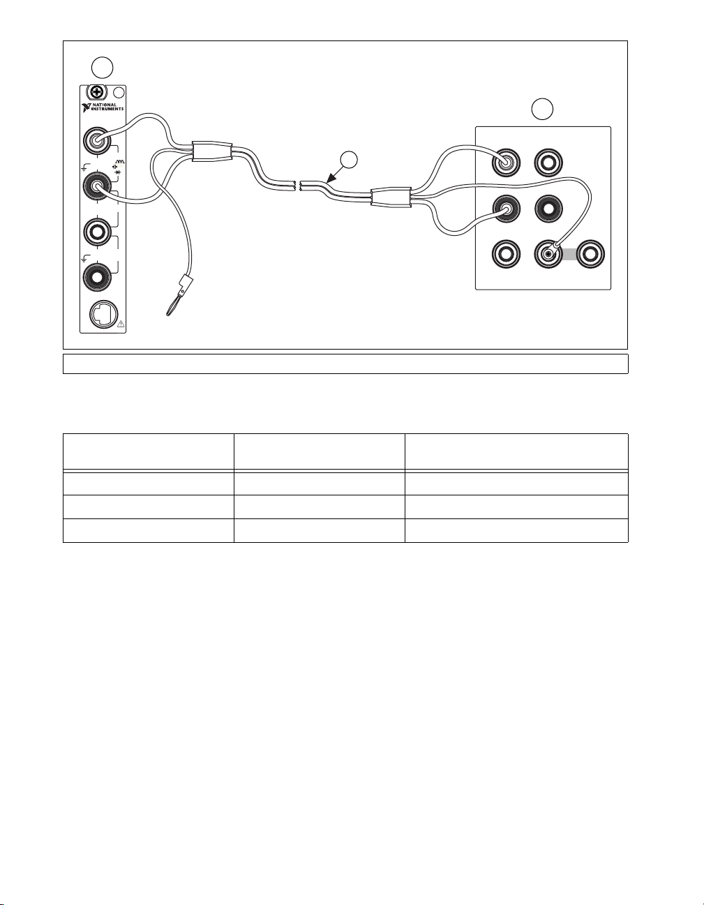
1
6½-Digit FlexDMM
OUTPUT
VΩA
HI
LO
HI
AUX
CURRENT
AUX
I/O
5V
MAX
300V
MAX
1A, 250V
MAX
300V
MAX
INPUT
V
AMPS
SENSE
W 4W
CAT II
HI
W
LO
HI
LO
3
1 NI 4070/4072 2 Fluke 5700A/5720A Calibrator 3 Fluke 5440 Cable
Figure 1. Cable Connections for Voltage and 2-Wire Resistance
Table 1. Fluke 5440 Cable Connections
Banana Plug Connector
(NI 4070/4072)
HI Red OUTPUT HI
LO Black OUTPUT LO
(No connection) Blue V GUARD
Banana Plug Color
(Fluke 5440 Cable)
Binding Post Label
(Fluke 5700A/5720A Calibrator)
2
SENSE
VΩ
HI
LO
GUARD GROUND
23. Wait two minutes for the thermal EMF to stabilize.
24. Generate 0 V on the calibrator.
25. Call
niDMM_ConfigureMeasurement with the following
parameters:
• Function =
NIDMM_VAL_DC_VOLTS
• Range = 0.1
• Resolution = 100e–9
26. Set the input resistance of the NI 4070/4072 to >10 GΩ by calling
niDMM_SetAttributeViReal64 with the following parameters:
• Attribute_ID =
NIDMM_ATTR_INPUT_RESISTANCE
• Attribute_Value = NIDMM_VAL_GREATER_THAN_10_GIGAOHM
NI 4070/4072 Calibration Procedure 10 ni.com
Page 11

27. Call niDMM_ConfigureMultiPoint with the following parameters:
• Trigger Count =
1
• Sample Count = 10
• Sample Trigger = NIDMM_VAL_IMMEDIATE
• Sample Interval = –1
28. Call niDMM_ReadMultiPoint with the following parameters:
• Maximum Time =
NIDMM_VAL_TIME_LIMIT_AUTO
• Array Size = 10
Average the results by summing the returned reading array of the
function and dividing by the returned actual number of points. Store
the result as the 100 mV >10 GΩ mode offset.
29. Set the input resistance of the NI 4070/4072 to 10 MΩ by calling
niDMM_SetAttributeViReal64 with the following parameters:
• Attribute_ID =
NIDMM_ATTR_INPUT_RESISTANCE
• Attribute_Value = NIDMM_VAL_10_MEGAOHM
30. Call niDMM_ConfigureMultiPoint with the following parameters:
• Trigger Count =
1
• Sample Count = 10
• Sample Trigger = NIDMM_VAL_IMMEDIATE
• SampleInterval = –1
31. Call niDMM_ReadMultiPoint with the following parameters:
• Maximum Time =
NIDMM_VAL_TIME_LIMIT_AUTO
• Array Size = 10
Average the results by summing the returned reading array of the
function and dividing by the returned actual number of points. Store
the result as the 100 mV 10 MΩ mode offset.
32. Output 100 mV on the calibrator with the range locked to 2.2 V.
This range prevents a 50 Ω calibrator output resistance from creating
a voltage divider with the internal resistance of the NI 4070/4072.
33. Call
niDMM_ConfigureMeasurement with the following
parameters:
• Function =
NIDMM_VAL_DC_VOLTS
• Range = 0.1
• Resolution = 100e–9
© National Instruments Corporation 11 NI 4070/4072 Calibration Procedure
Page 12

34. Set the input resistance of the NI 4070/4072 to >10 GΩ by calling
niDMM_SetAttributeViReal64 with the following parameters:
• Attribute_ID =
NIDMM_ATTR_INPUT_RESISTANCE
• Attribute_Value = NIDMM_VAL_GREATER_THAN_10_GIGAOHM
35. Call
niDMM_Read. Subtract the previously stored 100 mV >10 GΩ
mode offset from this measurement, and verify that the result falls
between the limits listed in Table 15.
36. Set the input resistance of the NI 4070/4072 to 10 MΩ by calling
niDMM_SetAttributeViReal64 with the following parameters:
• Attribute_ID =
NIDMM_ATTR_INPUT_RESISTANCE
• Attribute_Value = NIDMM_VAL_10_MEGAOHM
37. Call
niDMM_Read. Subtract the previously stored 100 mV 10 MΩ
mode offset from this measurement and verify that the result falls
between the limits listed in Table 15.
38. Output –100 mV on the calibrator with the range locked to 2.2 V.
This range prevents a 50 Ω calibrator output resistance from creating
a voltage divider with the internal resistance of the NI 4070/4072.
39. Set the input resistance of the NI 4070/4072 to >10 GΩ by calling
niDMM_SetAttributeViReal64 with the following parameters:
• Attribute_ID =
NIDMM_ATTR_INPUT_RESISTANCE
• Attribute_Value = NIDMM_VAL_GREATER_THAN_10_GIGAOHM
40. Call
niDMM_Read. Subtract the previously stored 100 mV >10 GΩ
mode offset from this measurement, and verify that the result falls
between the limits listed in Table 15.
41. Set the input resistance of the NI 4070/4072 to 10 MΩ by calling
niDMM_SetAttributeViReal64 with the following parameters:
• Attribute_ID =
NIDMM_ATTR_INPUT_RESISTANCE
• Attribute_Value = NIDMM_VAL_10_MEGAOHM
42. Call
niDMM_Read. Subtract the previously stored 100 mV 10 MΩ
mode offset from this measurement and verify that the result falls
between the limits listed in Table 15.
43. Output 1 V on the calibrator.
44. Call
niDMM_ConfigureMeasurement with the following
parameters:
• Function =
NIDMM_VAL_DC_VOLTS
• Range = 1
• Resolution = 1e–6
NI 4070/4072 Calibration Procedure 12 ni.com
Page 13

45. Set the input resistance of the NI 4070/4072 to >10 GΩ by calling
niDMM_SetAttributeViReal64 with the following parameters:
• Attribute_ID =
NIDMM_ATTR_INPUT_RESISTANCE
• Attribute_Value = NIDMM_VAL_GREATER_THAN_10_GIGAOHM
46. Call
niDMM_Read. Verify that this measurement falls between the
limits listed in Table 15.
47. Set the input resistance of the NI 4070/4072 to 10 MΩ by calling
niDMM_SetAttributeViReal64 with the following parameters:
• Attribute_ID =
NIDMM_ATTR_INPUT_RESISTANCE
• Attribute_Value = NIDMM_VAL_10_MEGAOHM
48. Call
niDMM_Read. Verify that this measurement falls between the
limits listed in Table 15.
49. Output –1 V on the calibrator.
50. Set the input resistance of the NI 4070/4072 to >10 GΩ by calling
niDMM_SetAttributeViReal64 with the following parameters:
• Attribute_ID =
NIDMM_ATTR_INPUT_RESISTANCE
• Attribute_Value = NIDMM_VAL_GREATER_THAN_10_GIGAOHM
51. Call
niDMM_Read. Verify that this measurement falls between the
limits listed in Table 15.
52. Set the input resistance of the NI 4070/4072 to 10 MΩ by calling
niDMM_SetAttributeViReal64 with the following parameters:
• Attribute_ID =
NIDMM_ATTR_INPUT_RESISTANCE
• Attribute_Value = NIDMM_VAL_10_MEGAOHM
53. Call
niDMM_Read. Verify that this measurement falls between the
limits listed in Table 15.
54. Output 10 V on the calibrator.
55. Call
niDMM_ConfigureMeasurement with the following
parameters:
• Function =
NIDMM_VAL_DC_VOLTS
• Range = 10
• Resolution = 10e–6
56. Set the input resistance of the NI 4070/4072 to >10 GΩ by calling
niDMM_SetAttributeViReal64 with the following parameters:
• Attribute_ID =
NIDMM_ATTR_INPUT_RESISTANCE
• Attribute_Value = NIDMM_VAL_GREATER_THAN_10_GIGAOHM
57. Call
niDMM_Read. Verify that this measurement falls between the
limits listed in Table 15.
© National Instruments Corporation 13 NI 4070/4072 Calibration Procedure
Page 14

58. Set the input resistance of the NI 4070/4072 to 10 MΩ by calling
niDMM_SetAttributeViReal64 with the following parameters:
• Attribute_ID =
NIDMM_ATTR_INPUT_RESISTANCE
• Attribute_Value = NIDMM_VAL_10_MEGAOHM
59. Call
niDMM_Read. Verify that this measurement falls between the
limits listed in Table 15.
60. Output –10 V on the calibrator.
61. Set the input resistance of the NI 4070/4072 to >10 GΩ by calling
niDMM_SetAttributeViReal64 with the following parameters:
• Attribute_ID =
NIDMM_ATTR_INPUT_RESISTANCE
• Attribute_Value = NIDMM_VAL_GREATER_THAN_10_GIGAOHM
62. Call
niDMM_Read. Verify that this measurement falls between the
limits listed in Table 15.
63. Set the input resistance of the NI 4070/4072 to 10 MΩ by calling
niDMM_SetAttributeViReal64 with the following parameters:
• Attribute_ID =
• Attribute_Value =
64. Call
niDMM_Read. Verify that this measurement falls between the
NIDMM_ATTR_INPUT_RESISTANCE
NIDMM_VAL_10_MEGAOHM
limits listed in Table 15.
65. Output 100 V on the calibrator.
Caution Avoid touching the connections when generating a high voltage from the
calibrator.
66. Call
niDMM_ConfigureMeasurement with the following
parameters:
• Function =
NIDMM_VAL_DC_VOLTS
• Range = 100
• Resolution = 100e–6
67. Set the input resistance of the NI 4070/4072 to 10 MΩ by calling
niDMM_SetAttributeViReal64 with the following parameters:
• Attribute_ID =
• Attribute_Value =
NIDMM_ATTR_INPUT_RESISTANCE
NIDMM_VAL_10_MEGAOHM
68. Call niDMM_Read. Verify that this measurement falls between the
limits listed in Table 15.
69. Output –100 V on the calibrator.
70. Call
niDMM_Read. Verify that this measurement falls between the
limits listed in Table 15.
NI 4070/4072 Calibration Procedure 14 ni.com
Page 15

71. Call niDMM_ConfigureMeasurement with the following
parameters:
• Function =
NIDMM_VAL_DC_VOLTS
• Range = 300
• Resolution = 300e–6
72. Call niDMM_Read. Before you apply the voltage, the DMM must be in
the 300 V range.
73. Output 300 V on the calibrator.
74. Call
niDMM_Read. Verify that this measurement falls between the
limits listed in Table 15.
75. Output –300 V on the calibrator.
76. Call
niDMM_Read. Verify that this measurement falls between the
limits listed in Table 15.
77. Reset the calibrator for safety reasons.
You have completed verifying the DC voltage of the NI 4070/4072. Select
one of the following options:
• If you want to continue verifying other modes, go to the Verifying AC
Voltage section.
• If you do not want to verify other modes and you are performing a
post-adjustment verification, go to the Completing the Adjustment
Procedures section.
• If you do not want to verify any additional modes and you are
performing a pre-adjustment verification, call
niDMM_close to close
the session.
Verifying AC Voltage
To verify AC voltage of the NI 4070/4072, complete the following steps:
1. Reset the calibrator.
2. Fasten the connectors on one end of the Fluke 5440 cable to the
appropriate banana plug connectors on the NI 4070/4072, and fasten
the connectors on the other end of the cable to the appropriate
calibrator binding posts. Figure 1 shows the correct connections.
Table 1 lists the cable connections.
3. Output 5 mV at 1 kHz on the calibrator.
4. Call
© National Instruments Corporation 15 NI 4070/4072 Calibration Procedure
niDMM_reset to reset the NI 4070/4072 to a known state.
Page 16

5. Call niDMM_ConfigureMeasurement with the following
parameters:
• Function =
NIDMM_VAL_AC_VOLTS
• Range = 0.05
• Resolution = 50e–9
6. Call niDMM_Read. Verify that this measurement falls between the
limits listed in Table 16.
7. Call
niDMM_ConfigureMeasurement with the following
parameters:
• Function =
NIDMM_VAL_AC_VOLTS_DCCOUPLED
• Range = 0.05
• Resolution = 50e–9
8. Call niDMM_Read. Verify that this measurement falls between the
limits listed in Table 16.
9. Output 50 mV at 30 Hz on the calibrator.
10. Call
niDMM_ConfigureMeasurement with the following
parameters:
• Function =
NIDMM_VAL_AC_VOLTS_DCCOUPLED
• Range = 0.05
• Resolution = 50e–9
11. Call niDMM_Read. Verify that this measurement falls between the
limits listed in Table 16.
12. Refer to Table 2 for the appropriate calibrator outputs and parameter
values as you complete the following steps:
a. On the calibrator, output the value listed in the Calibrator Output
column in Table 2 for the current iteration.
b. Call
niDMM_ConfigureMeasurement with Mode set to
NIDMM_VAL_AC_VOLTS and the remaining parameters as shown
in Table 2 for the current iteration.
c. Call
niDMM_Read. Verify that this measurement falls between the
limits listed in Table 16.
d. Call
niDMM_ConfigureMeasurement again, changing Mode to
NIDMM_VAL_AC_VOLTS_DCCOUPLED.
e. Call niDMM_Read. Verify that this measurement falls between the
limits listed in Table 16.
NI 4070/4072 Calibration Procedure 16 ni.com
Page 17
13. Repeat step 12 for each of the remaining iterations shown in Table 2.
Table 2. niDMM_ConfigureMeasurement Parameters
Calibrator Output niDMM_ConfigureMeasurement Parameters
Iteration
1 50 mV 50 Hz NIDMM_VAL_AC_VOLTS 0.05 50e–9
2 50 mV 1kHz NIDMM_VAL_AC_VOLTS 0.05 50e–9
3 50 mV 1kHz NIDMM_VAL_AC_VOLTS 0.5 500e–9
4 50 mV 20 kHz NIDMM_VAL_AC_VOLTS 0.05 50e–9
5 50 mV 50 kHz NIDMM_VAL_AC_VOLTS 0.05 50e–9
6 50 mV 100 kHz NIDMM_VAL_AC_VOLTS 0.05 50e–9
7 50 mV 300 kHz NIDMM_VAL_AC_VOLTS 0.05 50e–9
Amplitude Frequency Function Range Resolution
50 mV 50 Hz NIDMM_VAL_AC_VOLTS_DCCOUPLED 0.05 50e–9
50 mV 1kHz NIDMM_VAL_AC_VOLTS_DCCOUPLED 0.05 50e–9
50 mV 1kHz NIDMM_VAL_AC_VOLTS_DCCOUPLED 0.5 500e–9
50 mV 20 kHz NIDMM_VAL_AC_VOLTS_DCCOUPLED 0.05 50e–9
50 mV 50 kHz NIDMM_VAL_AC_VOLTS_DCCOUPLED 0.05 50e–9
50 mV 100 kHz NIDMM_VAL_AC_VOLTS_DCCOUPLED 0.05 50e–9
50 mV 300 kHz NIDMM_VAL_AC_VOLTS_DCCOUPLED 0.05 50e–9
14. Output 500 mV at 30 Hz on the calibrator.
15. Call
niDMM_ConfigureMeasurement with the following
parameters:
• Function =
NIDMM_VAL_AC_VOLTS_DCCOUPLED
• Range = 0.5
• Resolution = 500e–9
16. Call niDMM_Read. Verify that this measurement falls between the
limits listed in Table 16.
17. Refer to Table 3 for the appropriate calibrator outputs and parameter
values as you complete the following steps:
a. On the calibrator, output the value listed in the Calibrator Output
column in Table 3 for the current iteration.
b. Call
niDMM_ConfigureMeasurement with Mode set to
NIDMM_VAL_AC_VOLTS and the remaining parameters as shown
in Table 3 for the current iteration.
© National Instruments Corporation 17 NI 4070/4072 Calibration Procedure
Page 18
c. Call niDMM_Read. Verify that this measurement falls between the
limits listed in Table 16.
d. Call
e. Call
niDMM_ConfigureMeasurement again, changing Mode to
NIDMM_VAL_AC_VOLTS_DCCOUPLED.
niDMM_Read. Verify that this measurement falls between the
limits listed in Table 16.
Table 3. niDMM_ConfigureMeasurement Parameters
Calibrator Output niDMM_ConfigureMeasurement Parameters
Iteration
Amplitude Frequency Function Range Resolution
1 500 mV 50 Hz NIDMM_VAL_AC_VOLTS 0.5 500e–9
500 mV 50 Hz NIDMM_VAL_AC_VOLTS_DCCOUPLED 0.5 500e–9
2 500 mV 1kHz NIDMM_VAL_AC_VOLTS 0.5 500e–9
500 mV 1kHz NIDMM_VAL_AC_VOLTS_DCCOUPLED 0.5 500e–9
3 500 mV 1kHz NIDMM_VAL_AC_VOLTS 5 5e–6
500 mV 1kHz NIDMM_VAL_AC_VOLTS_DCCOUPLED 5 5e–6
4 500 mV 20 kHz NIDMM_VAL_AC_VOLTS 0.5 500e–9
500 mV 20 kHz NIDMM_VAL_AC_VOLTS_DCCOUPLED 0.5 500e–9
5 500 mV 50 kHz NIDMM_VAL_AC_VOLTS 0.5 500e–9
500 mV 50 kHz NIDMM_VAL_AC_VOLTS_DCCOUPLED 0.5 500e–9
6 500 mV 100 kHz NIDMM_VAL_AC_VOLTS 0.5 500e–9
500 mV 100 kHz NIDMM_VAL_AC_VOLTS_DCCOUPLED 0.5 500e–9
7 500 mV 300 kHz NIDMM_VAL_AC_VOLTS 0.5 500e–9
500 mV 300 kHz NIDMM_VAL_AC_VOLTS_DCCOUPLED 0.5 500e–9
18. Output 5 V at 30 Hz on the calibrator.
19. Call
niDMM_ConfigureMeasurement with the following
parameters:
• Function =
NIDMM_VAL_AC_VOLTS_DCCOUPLED
• Range = 5
• Resolution = 5e–6
20. Call niDMM_Read. Verify that this measurement falls between the
limits listed in Table 16.
NI 4070/4072 Calibration Procedure 18 ni.com
Page 19

21. Refer to Table 4 for the appropriate calibrator outputs and parameter
values as you complete the following steps:
a. On the calibrator, output the value listed in the Calibrator Output
column in Table 4 for the current iteration.
b. Call
niDMM_ConfigureMeasurement with Mode set to
NIDMM_VAL_AC_VOLTS and the remaining parameters as shown
in Table 4 for the current iteration.
c. Call
niDMM_Read. Verify that this measurement falls between the
limits listed in Table 16.
d. Call
e. Call
niDMM_ConfigureMeasurement again, changing Mode to
NIDMM_VAL_AC_VOLTS_DCCOUPLED.
niDMM_Read. Verify that this measurement falls between the
limits listed in Table 16.
Table 4. niDMM_ConfigureMeasurement Parameters
Calibrator Output niDMM_ConfigureMeasurement Parameters
Iteration
1 5V 50 Hz NIDMM_VAL_AC_VOLTS 5 5e–6
2 5V 1kHz NIDMM_VAL_AC_VOLTS 5 5e–6
3 5V 1kHz NIDMM_VAL_AC_VOLTS 50 50e–6
4 5V 1kHz NIDMM_VAL_AC_VOLTS 300 300e–6
5 5V 20 kHz NIDMM_VAL_AC_VOLTS 5 5e–6
6 5V 50 kHz NIDMM_VAL_AC_VOLTS 5 5e–6
7 5V 100 kHz NIDMM_VAL_AC_VOLTS 5 5e–6
8 5V 300 kHz NIDMM_VAL_AC_VOLTS 5 5e–6
Amplitude Frequency Function Range Resolution
5V 50 Hz NIDMM_VAL_AC_VOLTS_DCCOUPLED 5 5e–6
5V 1kHz NIDMM_VAL_AC_VOLTS_DCCOUPLED 5 5e–6
5V 1kHz NIDMM_VAL_AC_VOLTS_DCCOUPLED 50 50e–6
5V 1kHz NIDMM_VAL_AC_VOLTS_DCCOUPLED 300 300e–6
5V 20 kHz NIDMM_VAL_AC_VOLTS_DCCOUPLED 5 5e–6
5V 50 kHz NIDMM_VAL_AC_VOLTS_DCCOUPLED 5 5e–6
5V 100 kHz NIDMM_VAL_AC_VOLTS_DCCOUPLED 5 5e–6
5V 300 kHz NIDMM_VAL_AC_VOLTS_DCCOUPLED 5 5e–6
22. Output 50 V at 30 Hz on the calibrator.
© National Instruments Corporation 19 NI 4070/4072 Calibration Procedure
Page 20
23. Call niDMM_ConfigureMeasurement with the following
parameters:
• Function =
NIDMM_VAL_AC_VOLTS_DCCOUPLED
• Range = 50
• Resolution = 50e–6
24. Call niDMM_Read. Verify that this measurement falls between the
limits listed in Table 16.
25. Refer to Table 5 for the appropriate calibrator outputs and parameter
values as you complete the following steps:
a. On the calibrator, output the value listed in the Calibrator Output
column in Table 5 for the current iteration.
b. Call
niDMM_ConfigureMeasurement with Mode set to
NIDMM_VAL_AC_VOLTS and the remaining parameters as shown
in Table 5 for the current iteration.
c. Call
niDMM_Read. Verify that this measurement falls between the
limits listed in Table 16.
d. Call
e. Call
niDMM_ConfigureMeasurement again, changing Mode to
NIDMM_VAL_AC_VOLTS_DCCOUPLED.
niDMM_Read. Verify that this measurement falls between the
limits listed in Table 16.
Table 5. niDMM_ConfigureMeasurement Parameters
Calibrator Output niDMM_ConfigureMeasurement Parameters
Iteration
1 50 V 50 Hz NIDMM_VAL_AC_VOLTS 50 50e–6
2 50 V 1kHz NIDMM_VAL_AC_VOLTS 50 50e–6
3 50 V 20 kHz NIDMM_VAL_AC_VOLTS 50 50e–6
4 50 V 50 kHz NIDMM_VAL_AC_VOLTS 50 50e–6
5 50 V 100 kHz NIDMM_VAL_AC_VOLTS 50 50e–6
6 50 V 300 kHz NIDMM_VAL_AC_VOLTS 50 50e–6
NI 4070/4072 Calibration Procedure 20 ni.com
Amplitude Frequency Function Range Resolution
50 V 50 Hz NIDMM_VAL_AC_VOLTS_DCCOUPLED 50 50e–6
50 V 1kHz NIDMM_VAL_AC_VOLTS_DCCOUPLED 50 50e–6
50 V 20 kHz NIDMM_VAL_AC_VOLTS_DCCOUPLED 50 50e–6
50 V 50 kHz NIDMM_VAL_AC_VOLTS_DCCOUPLED 50 50e–6
50 V 100 kHz NIDMM_VAL_AC_VOLTS_DCCOUPLED 50 50e–6
50 V 300 kHz NIDMM_VAL_AC_VOLTS_DCCOUPLED 50 50e–6
Page 21

26. Call niDMM_ConfigureMeasurement with the following
parameters:
• Function =
NIDMM_VAL_AC_VOLTS_DCCOUPLED
• Range = 300
• Resolution = 300e–6
27. Call niDMM_Read. The DMM must be in the 300 V range before you
apply the voltage.
28. Output 219 V at 30 Hz on the calibrator.
29. Call
niDMM_Read. Verify that this measurement falls between the
limits listed in Table 16.
30. Refer to Table 6 for the appropriate calibrator outputs and parameter
values as you complete the following steps:
a. On the calibrator, output the value listed in the Calibrator Output
column in Table 6 for the current iteration.
b. Call
niDMM_ConfigureMeasurement with Mode set to
NIDMM_VAL_AC_VOLTS and the remaining parameters as shown
in Table 6 for the current iteration.
c. Call
niDMM_Read. Verify that this measurement falls between the
limits listed in Table 16.
d. Call
e. Call
niDMM_ConfigureMeasurement again, changing Mode to
NIDMM_VAL_AC_VOLTS_DCCOUPLED.
niDMM_Read. Verify that this measurement falls between the
limits listed in Table 16.
Table 6. niDMM_ConfigureMeasurement Parameters
Calibrator Output niDMM_ConfigureMeasurement Parameters
Iteration
1 219 V 50 Hz NIDMM_VAL_AC_VOLTS 300 300e–6
2 219 V 1kHz NIDMM_VAL_AC_VOLTS 300 300e–6
3 219 V 20 kHz NIDMM_VAL_AC_VOLTS 300 300e–6
4 219 V 50 kHz NIDMM_VAL_AC_VOLTS 300 300e–6
5 70 V 300 kHz NIDMM_VAL_AC_VOLTS 300 300e–6
© National Instruments Corporation 21 NI 4070/4072 Calibration Procedure
Amplitude Frequency Function Range Resolution
219 V 50 Hz NIDMM_VAL_AC_VOLTS_DCCOUPLED 300 300e–6
219 V 1kHz NIDMM_VAL_AC_VOLTS_DCCOUPLED 300 300e–6
219 V 20 kHz NIDMM_VAL_AC_VOLTS_DCCOUPLED 300 300e–6
219 V 50 kHz NIDMM_VAL_AC_VOLTS_DCCOUPLED 300 300e–6
70 V 300 kHz NIDMM_VAL_AC_VOLTS_DCCOUPLED 300 300e–6
Page 22

31. Reset the calibrator for safety reasons.
You have completed verifying the AC voltage of the NI 4070/4072. Select
one of the following options:
• If you want to continue verifying other modes, go to the Verifying
4-Wire Resistance section.
• If you do not want to verify other modes and you are performing a
post-adjustment verification, go to the Completing the Adjustment
Procedures section.
• If you do not want to verify any additional modes and you are
performing a pre-adjustment verification, call
niDMM_close to close
the session.
Verifying 4-Wire Resistance
To verify the 4-wire resistance of the NI 4070/4072, complete the
following steps:
1. Reset the calibrator.
2. Fasten the connectors on one end of each Fluke 5440 cable to the
appropriate banana plug connectors on the NI 4070/4072. Fasten the
connectors on the other end of each Fluke 5440 cable to the appropriate
calibrator binding posts. Figure 2 shows the Fluke 5440 cables. Table 7
lists the cable connections.
1
VΩA
AUX
2
SENSE
VΩ
HI
LO
GUARD GROUND
6½-Digit FlexDMM
OUTPUT
HI
LO
HI
CURRENT
AUX
I/O
5V
MAX
300V
MAX
1A, 250V
MAX
300V
MAX
INPUT
V
AMPS
SENSE
W 4W
CAT II
HI
W
LO
HI
3
LO
1 NI 4070/4072 2 Fluke 5700A/5720A Calibrator 3 Fluke 5440 Cables
Figure 2. Cable Connections for 4-Wire Resistance
NI 4070/4072 Calibration Procedure 22 ni.com
Page 23

Table 7. Fluke 5440 Cable Connections
Fluke 5440
Cable Identification
First cable HI Red OUTPUT HI
Second cable HI SENSE Red SENSE HI
Banana Plug Connector
(NI 4070/4072)
LO Black OUTPUT LO
(No connection) Blue V GUARD
LO SENSE Black SENSE LO
(No connection) Blue V GUARD
Banana Plug Color
(Fluke 5440 Cable)
(Fluke 5700A/5720A Calibrator)
3. Wait two minutes for the thermal EMF to stabilize if the Fluke 5440
cables were not previously connected in this configuration.
4. Call
niDMM_reset.
5. Refer to Table 8 for the appropriate calibrator output and function
parameter values as you complete the following steps:
a. On the calibrator, output the value listed in the Calibrator Output
column in Table 8 for the current iteration. Make sure that the
external sense is turned on but 2-wire compensation is turned off.
Note After setting the calibrator output to 0 Ω in the seventh iteration, you do not need to
continually set the calibrator to 0 Ω for iterations 8 through 12.
Binding Post
b. Call
niDMM_ConfigureMeasurement with the parameters set
as shown in Table 8 for the current iteration.
c. Call
niDMM_ConfigureOffsetCompOhms with
OffsetCompOhms set to either
NIDMM_VAL_OFFSET_COMP_OHMS_ON or
NIDMM_VAL_OFFSET_COMP_OHMS_OFF according to Table 8 for
the current iteration.
d. Call
niDMM_Read. Verify that this measurement falls between the
tolerances listed in Table 17. Tolerances are provided instead of
absolute limits because your calibrator will have different discrete
resistance values.
© National Instruments Corporation 23 NI 4070/4072 Calibration Procedure
Page 24

6. Repeat step 5 for each of the remaining iterations listed in Table 8.
Table 8. niDMM_ConfigureMeasurement Parameters
Calibrator
Iteration
1 10 MΩ NIDMM_VAL_4_WIRE_RES 10e6 10 OFF
2 1MΩ NIDMM_VAL_4_WIRE_RES 1e6 1 OFF
3 100 kΩ NIDMM_VAL_4_WIRE_RES 100e3 0.1 OFF
4 10 kΩ NIDMM_VAL_4_WIRE_RES 10e3 0.01 ON
5 1kΩ NIDMM_VAL_4_WIRE_RES 1e3 1e–3 ON
6 100 Ω NIDMM_VAL_4_WIRE_RES 100 100e–6 ON
7 0 Ω NIDMM_VAL_4_WIRE_RES 10e6 10 OFF
8 0 Ω NIDMM_VAL_4_WIRE_RES 1e6 1 OFF
9 0 Ω NIDMM_VAL_4_WIRE_RES 100e3 0.1 OFF
10 0 Ω NIDMM_VAL_4_WIRE_RES 10e3 0.01 ON
11 0 Ω NIDMM_VAL_4_WIRE_RES 1e3 1e–3 ON
12 0 Ω NIDMM_VAL_4_WIRE_RES 100 100e–6 ON
Output
niDMM_ConfigureMeasurement Parameters
OffsetCompOhmsFunction Range Resolution
You have completed verifying the 4-wire resistance of the NI 4070/4072.
Select one of the following options:
• If you want to continue verifying other modes, go to the Verifying
2-Wire Resistance section.
• If you do not want to verify other modes and you are performing a
post-adjustment verification, go to the Completing the Adjustment
Procedures section.
• If you do not want to verify any additional modes and you are
performing a pre-adjustment verification, call
niDMM_close to close
the session.
Verifying 2-Wire Resistance
To verify the 2-wire resistance of the NI 4070/4072, complete the
following steps:
1. Plug in the insulated banana plug shorting bar across the HI and LO
banana plug connectors on the NI 4070/4072.
2. Wait one minute for the thermal EMF to stabilize.
3. Call
NI 4070/4072 Calibration Procedure 24 ni.com
niDMM_reset.
Page 25

4. Call niDMM_ConfigureMeasurement with the following
parameters:
• Function =
NIDMM_VAL_2_WIRE_RES
• Range = 10e3
• Resolution = 0.01
5. Call niDMM_ConfigureOffsetCompOhms with OffsetCompOhms
set to
NIDMM_VAL_OFFSET_COMP_OHMS_ON.
6. Call
niDMM_Read. Verify that this measurement falls between the
limits listed in Table 18.
7. Call
niDMM_ConfigureMeasurement with the following
parameters:
• Function =
NIDMM_VAL_2_WIRE_RES
• Range = 1e3
• Resolution = 1e–3
8. Call niDMM_ConfigureOffsetCompOhms with OffsetCompOhms
set to
NIDMM_VAL_OFFSET_COMP_OHMS_ON.
9. Call
niDMM_Read. Verify that this measurement falls between the
limits listed in Table 18.
10. Call
niDMM_ConfigureMeasurement with the following
parameters:
• Function =
NIDMM_VAL_2_WIRE_RES
• Range = 100
• Resolution = 100e–6
11. Call niDMM_ConfigureOffsetCompOhms with OffsetCompOhms
set to
NIDMM_VAL_OFFSET_COMP_OHMS_ON.
12. Call
niDMM_Read. Verify that this measurement falls between the
limits listed in Table 18.
13. Remove the shorting bar from the NI 4070/4072.
14. Reset the calibrator.
15. Fasten the connectors on one end of the Fluke 5440 cable to the
NI 4070/4072, and fasten the connectors on the other end of the cable
to the appropriate calibrator binding posts. Figure 1 shows the correct
connections. Table 1 lists the cable connections.
16. Wait two minutes for the thermal EMF to stabilize if the Fluke 5440
cable was not previously used in this configuration.
17. Output 0 Ω on the calibrator with 2-wire compensation turned on
but with external sense turned off.
18. Call
niDMM_reset to reset the NI 4070/4072 to a known state.
© National Instruments Corporation 25 NI 4070/4072 Calibration Procedure
Page 26

19. Call niDMM_ConfigureMeasurement with the following
parameters:
• Function =
NIDMM_VAL_2_WIRE_RES
• Range = 100e6
• Resolution = 100
20. Call niDMM_Read and store the result as the 100 MΩ range offset.
21. Call
niDMM_ConfigureMeasurement with the following
parameters:
• Function =
NIDMM_VAL_2_WIRE_RES
• Range = 10e6
• Resolution = 10
22. Call niDMM_Read and store the result as the 10 MΩ range offset.
23. Call
niDMM_ConfigureMeasurement with the following
parameters:
• Function =
NIDMM_VAL_2_WIRE_RES
• Range = 1e6
• Resolution = 1
24. Call niDMM_Read and store the result as the 1 MΩ range offset.
25. Call
niDMM_ConfigureMeasurement with the following
parameters:
• Function =
NIDMM_VAL_2_WIRE_RES
• Range = 100e3
• Resolution = 0.1
26. Call niDMM_ConfigureMultiPoint with the following parameters:
• Trigger Count =
1
• Sample Count = 4
• Sample Trigger = NIDMM_VAL_IMMEDIATE
• Sample Interval = –1
27. Call niDMM_ReadMultiPoint with the following parameters:
• Maximum Time =
NIDMM_VAL_TIME_LIMIT_AUTO
• Array Size = 4
Average the results by summing the returned reading array of the
function and dividing by the returned actual number of points.
Store the result as the 100 kΩ range offset.
NI 4070/4072 Calibration Procedure 26 ni.com
Page 27

28. Call niDMM_ConfigureMeasurement with the following
parameters:
• Function =
NIDMM_VAL_2_WIRE_RES
• Range = 10e3
• Resolution = 0.01
29. Call niDMM_ConfigureMultiPoint with the following parameters:
• Trigger Count =
1
• Sample Count = 4
• Sample Trigger = NIDMM_VAL_IMMEDIATE
• Sample Interval = –1
30. Call niDMM_ReadMultiPoint with the following parameters:
• Maximum Time =
NIDMM_VAL_TIME_LIMIT_AUTO
• Array Size = 4
Average the results by summing the returned reading array of the
function and dividing by the returned actual number of points.
Store the result as the 10 kΩ range offset.
31. Call
niDMM_ConfigureMeasurement with the following
parameters:
• Function =
NIDMM_VAL_2_WIRE_RES
• Range = 1e3
• Resolution = 1e–3
32. Call niDMM_ConfigureMultiPoint with the following parameters:
• Trigger Count =
1
• Sample Count = 4
• Sample Trigger = NIDMM_VAL_IMMEDIATE
• Sample Interval = –1
33. Call niDMM_ReadMultiPoint with the following parameters:
• Maximum Time =
NIDMM_VAL_TIME_LIMIT_AUTO
• Array Size = 4
Average the results by summing the returned reading array of the
function and dividing by the returned actual number of points.
Store the result as the 1 kΩ range offset.
34. Call
niDMM_ConfigureMeasurement with the following
parameters:
• Function =
NIDMM_VAL_2_WIRE_RES
• Range = 100
• Resolution = 100e–6
© National Instruments Corporation 27 NI 4070/4072 Calibration Procedure
Page 28

35. Call niDMM_ConfigureMultiPoint with the following parameters:
• Trigger Count =
1
• Sample Count = 10
• Sample Trigger = NIDMM_VAL_IMMEDIATE
• Sample Interval = –1
36. Call niDMM_ReadMultiPoint with the following parameters:
• Maximum Time =
NIDMM_VAL_TIME_LIMIT_AUTO
• Array Size = 10
Average the results by summing the returned reading array of the
function and dividing by the returned actual number of points.
Store the result as the 100 Ω range offset.
37. Output 100 MΩ on the calibrator without external sense or 2-wire
compensation.
38. Call
niDMM_ConfigureMeasurement with the following
parameters:
• Function =
NIDMM_VAL_2_WIRE_RES
• Range = 100e6
• Resolution = 100
39. Call niDMM_Read. Subtract the previously stored 100 MΩ range offset
from this measurement. Verify that the result falls between the
tolerances listed in Table 18.
40. Output 10 MΩ on the calibrator without external sense or 2-wire
compensation.
41. Call
niDMM_ConfigureMeasurement with the following
parameters:
• Function =
NIDMM_VAL_2_WIRE_RES
• Range = 10e6
• Resolution = 10
42. Call
niDMM_Read. Subtract the previously stored 10 MΩ range offset
from this measurement. Verify that the result falls between the
tolerances listed in Table 18.
43. Output 1 MΩ on the calibrator without external sense or 2-wire
compensation.
44. Call
niDMM_ConfigureMeasurement with the following
parameters:
• Function =
NIDMM_VAL_2_WIRE_RES
• Range = 1e6
• Resolution = 1
NI 4070/4072 Calibration Procedure 28 ni.com
Page 29

45. Call niDMM_Read. Subtract the previously stored 1 MΩ range offset
from this measurement. Verify that the result falls between the
tolerances listed in Table 18.
46. Output 100 kΩ on the calibrator without external sense or 2-wire
compensation.
47. Call
niDMM_ConfigureMeasurement with the following
parameters:
• Function =
NIDMM_VAL_2_WIRE_RES
• Range = 100e3
• Resolution = 0.1
48. Call niDMM_Read. Subtract the previously stored 100 kΩ range offset
from this measurement. Verify that the result falls between the
tolerances listed in Table 18.
49. Output 10 kΩ on the calibrator with 2-wire compensation turned on
but with external sense turned off.
50. Call
niDMM_ConfigureMeasurement with the following
parameters:
• Function =
NIDMM_VAL_2_WIRE_RES
• Range = 10e3
• Resolution = 0.01
51. Call niDMM_Read. Subtract the previously stored 10 kΩ range offset
from this measurement. Verify that the result falls between the
tolerances listed in Table 18.
52. Output 1 kΩ on the calibrator with 2-wire compensation turned on
but with external sense turned off.
53. Call
niDMM_ConfigureMeasurement with the following
parameters:
• Function =
NIDMM_VAL_2_WIRE_RES
• Range = 1e3
• Resolution = 1e–3
54. Call niDMM_Read. Subtract the previously stored 1 kΩ range offset
from this measurement. Verify that the result falls between the
tolerances listed in Table 18.
55. Output 100 Ω on the calibrator with 2-wire compensation turned on
but with external sense turned off.
56. Call
niDMM_ConfigureMeasurement with the following
parameters:
• Function =
NIDMM_VAL_2_WIRE_RES
• Range = 100
• Resolution = 100e–6
© National Instruments Corporation 29 NI 4070/4072 Calibration Procedure
Page 30

57. Call niDMM_Read. Subtract the previously calculated 100 Ω range
offset from this measurement. Verify that the result falls between the
tolerances listed in Table 18.
You have completed verifying the 2-wire resistance of the NI 4070/4072.
Select one of the following options:
• If you want to continue verifying other modes, go to the Verifying DC
Current section.
• If you do not want to verify other modes and you are performing a
post-adjustment verification, go to the Completing the Adjustment
Procedures section.
• If you do not want to verify any additional modes and you are
performing a pre-adjustment verification, call
niDMM_close to close
the session.
Verifying DC Current
To verify the DC current of the NI 4070/4072, complete the following steps:
1. Reset the calibrator.
2. Fasten the connectors on one end of the Fluke 5440 cable to the
NI 4070/4072 HI SENSE and LO banana plug connectors, and connect
the connectors on the other end of the cable to the HI and LO calibrator
binding posts. Figure 3 shows the correct connections. Table 9 lists the
cable connections.
1
VΩA
AUX
2
SENSE
VΩ
HI
LO
GUARD GROUND
6½-Digit FlexDMM
OUTPUT
HI
LO
HI
CURRENT
AUX
I/O
5V
MAX
300V
MAX
1A, 250V
MAX
300V
MAX
INPUT
V
AMPS
SENSE
W 4W
CAT II
HI
W
LO
HI
LO
3
1 NI 4070/4072 2 Fluke 5700A/5720A Calibrator 3 Fluke 5440 Cable
Figure 3. Cable Connections for Current
NI 4070/4072 Calibration Procedure 30 ni.com
Page 31

Table 9. Fluke 5440 Cable Connections
Banana Plug Connector
(NI 4070/4072)
HI SENSE Red OUTPUT HI
LO Black OUTPUT LO
(No connection) Blue V GUARD
Banana Plug Color
(Fluke 5440 Cable)
(Fluke 5700A/5720A Calibrator)
3. Call niDMM_reset to reset the NI 4070/4072 to a known state.
4. Set the current output on the calibrator to NORM and output 0 A.
5. Call
niDMM_ConfigureMeasurement with the following
parameters:
• Function =
NIDMM_VAL_DC_CURRENT
• Range = 0.02
• Resolution = 20e–9
6. Call niDMM_Read. Verify that this measurement falls between the
limits listed in Table 19.
7. Call
niDMM_ConfigureMeasurement with the following
parameters:
• Function =
NIDMM_VAL_DC_CURRENT
• Range = 0.2
• Resolution = 200e–9
8. Call niDMM_Read. Verify that this measurement falls between the
limits listed in Table 19.
9. Call
niDMM_ConfigureMeasurement with the following
parameters:
• Function =
NIDMM_VAL_DC_CURRENT
• Range = 1
• Resolution = 1e–6
10. Call niDMM_Read. Verify that this measurement falls between the
limits listed in Table 19.
11. Call
niDMM_ConfigureMeasurement with the following
parameters:
• Function =
NIDMM_VAL_DC_CURRENT
• Range = 0.02
• Resolution = 20e–9
12. Call niDMM_Read to configure the NI 4070/4072 for a current mode
before applying current.
Binding Post
© National Instruments Corporation 31 NI 4070/4072 Calibration Procedure
Page 32

13. Output 20 mA on the calibrator.
14. Call
niDMM_Read. Verify that this measurement falls between the
limits listed in Table 19.
15. Output –20 mA on the calibrator.
16. Call
niDMM_Read. Verify that this measurement falls between the
limits listed in Table 19.
17. Output 200 mA on the calibrator.
18. Call
niDMM_ConfigureMeasurement with the following
parameters:
• Function =
NIDMM_VAL_DC_CURRENT
• Range = 0.2
• Resolution = 200e–9
19. Call niDMM_Read. Verify that this measurement falls between the
limits listed in Table 19.
20. Output –200 mA on the calibrator.
21. Call
niDMM_Read. Verify that this measurement falls between the
limits listed in Table 19.
22. Output 1 A on the calibrator.
23. Call
niDMM_ConfigureMeasurement with the following
parameters:
• Function =
NIDMM_VAL_DC_CURRENT
• Range = 1
• Resolution =
1e–6
24. Call niDMM_Read. Verify that this measurement falls between the
limits listed in Table 19.
25. Output –1 A on the calibrator.
26. Call
niDMM_Read. Verify that this measurement falls between the
limits listed in Table 19.
You have completed verifying the DC current of the NI 4070/4072. Select
one of the following options:
• If you want to continue verifying other modes, go to the Verifying AC
Current section.
• If you do not want to verify other modes and you are performing a
post-adjustment verification, go to the Completing the Adjustment
Procedures section.
• If you do not want to verify any additional modes and you are
performing a pre-adjustment verification, call
niDMM_close to close
the session.
NI 4070/4072 Calibration Procedure 32 ni.com
Page 33

Verifying AC Current
To verify the AC current of the NI 4070/4072, complete the following
steps:
1. Reset the calibrator.
2. Fasten the connectors on one end of the Fluke 5440 cable to the
NI 4070/4072 HI SENSE and LO banana plug connectors, and fasten
the connectors on the other end of the cable to the HI and LO calibrator
binding posts. Figure 3 shows the correct connections. Table 9 lists the
cable connections.
3. Call
4. Call
5. Call niDMM_Read to configure the NI 4070/4072 for a current mode
6. Output 1 mA at 1 kHz on the calibrator with the current output set
7. Call
8. Output 10 mA at 1 kHz on the calibrator.
9. Call
10. Call
11. Call niDMM_Read. Verify that this measurement falls between the
12. Output 100 mA at 1 kHz on the calibrator.
13. Call
niDMM_reset to reset the NI 4070/4072 to a known state.
niDMM_ConfigureMeasurement with the following
parameters:
• Function =
NIDMM_VAL_AC_CURRENT
• Range = 0.01
• Resolution = 10e–9
before applying current.
to
NORM.
niDMM_Read. Verify that this measurement falls between the
limits listed in Table 20.
niDMM_Read. Verify that this measurement falls between the
limits listed in Table 20.
niDMM_ConfigureMeasurement with the following
parameters:
• Function =
NIDMM_VAL_AC_CURRENT
• Range = 0.1
• Resolution = 100e–9
limits listed in Table 20.
niDMM_Read. Verify that this measurement falls between the
limits listed in Table 20.
© National Instruments Corporation 33 NI 4070/4072 Calibration Procedure
Page 34

14. Call niDMM_ConfigureMeasurement with the following
parameters:
• Function =
NIDMM_VAL_AC_CURRENT
• Range = 1
• Resolution = 1e–6
15. Call niDMM_Read. Verify that this measurement falls between the
limits listed in Table 20.
16. Output 1 A at 1 kHz on the calibrator.
17. Call
niDMM_Read. Verify that this measurement falls between the
limits listed in Table 20.
You have completed verifying the AC current of the NI 4070/4072. Select
one of the following options:
• If you want to continue verifying other modes, go to the Verifying
Frequency section.
• If you do not want to verify other modes and you are performing a
post-adjustment verification, go to the Completing the Adjustment
Procedures section.
• If you do not want to verify any additional modes and you are
performing a pre-adjustment verification, call
niDMM_close to close
the session.
Verifying Frequency
Notes The frequency of the NI 4070/4072 is not user adjustable. If this verification
procedure indicates that the frequency is out of specification, return the NI 4070/4072
to NI for repair.
This verification procedure is optional and requires additional test
equipment. If you do not want to verify frequency, select one of the
following options:
• If you are calibrating an NI 4072 and want to continue verifying other
modes, go to the Verifying Capacitance and Inductance (NI 4072
Only) section.
• If you do not want to verify other modes and are performing a
post-adjustment verification, go to the Completing the Adjustment
Procedures section.
• If you do not want to verify any additional modes and you are
performing a pre-adjustment verification, call
the session.
NI 4070/4072 Calibration Procedure 34 ni.com
niDMM_close to close
Page 35

To verify the frequency of the NI 4070/4072, complete the following steps:
1. Remove all connections from the NI 4070/4072.
Note Polarity is not important in steps 2, 3, and 5.
2. Connect one end of the coaxial cable to the Pomona 4892 double
banana plug.
3. Tighten the other end of the coaxial cable in the screw terminal
channels 5 and 39 of the TB-2715 terminal block.
4. Connect the TB-2715 with the coaxial cable attached to the NI 6608.
5. Plug the Pomona 4892 into the HI and LO terminals of the
NI 4070/4072.
6. Call
7. Call
niDMM_reset to reset the NI 4070/4072 to a known state.
niDMM_ConfigureMeasurement with the following
parameters:
• Function =
NIDMM_VAL_FREQ
• Range = 1
• Resolution = 0
8. Call niDMM_ConfigureFrequencyVoltageRange with
Voltage Range set to
9. Call
GPCTR_Control with the following parameters:
5.
• deviceNumber = the device number of the NI 6608, assigned by
Measurement & Automation Explorer (MAX)
• gpctrNum =
ND_COUNTER_0
• action = ND_RESET
10. Call GPCTR_Set_Application with the following parameters:
• deviceNumber = the device number of the NI 6608, assigned
by MAX
• gpctrNum =
ND_COUNTER_0
• application = ND_PULSE_TRAIN_GNR
11. Call GPCTR_Change_Parameter with the following parameters:
• deviceNumber = the device number of the NI 6608, assigned
by MAX
• gpctrNum =
ND_COUNTER_0
• paramID = ND_COUNT_1
• paramValue = 10e6
© National Instruments Corporation 35 NI 4070/4072 Calibration Procedure
Page 36

12. Call GPCTR_Change_Parameter with the following parameters:
• deviceNumber = the device number of the NI 6608, assigned
by MAX
• gpctrNum =
ND_COUNTER_0
• paramID = ND_COUNT_2
• paramValue = 10e6
13. Call GPCTR_Control with the following parameters:
• deviceNumber = the device number of the NI 6608, assigned
by MAX
• gpctrNum =
ND_COUNTER_0
• action = ND_PROGRAM
14. Call niDMM_Read. Verify that this measurement falls between the
limits listed in Table 21.
15. Call
GPCTR_Control with the following parameters:
• deviceNumber = the device number of the NI 6608, assigned
by MAX
• gpctrNum =
ND_COUNTER_0
• action = ND_RESET
16. Repeat steps 10 through 15 with the following modification: in
steps 11 and 12, change paramValue to
function
GPCTR_Change_Parameter.
500 when you call the
17. Repeat steps 10 through 15 with the following modification: in
steps 11 and 12, change paramValue to
GPCTR_Change_Parameter.
20 when you call the function
You have completed verifying the frequency of the NI 4070/4072. Select
one of the following options:
• If you are calibrating an NI 4072 and want to continue verifying other
modes, go to the Verifying Capacitance and Inductance (NI 4072
Only) section.
• If you do not want to verify other modes and you are performing a
post-adjustment verification, go to the Completing the Adjustment
Procedures section.
• If you do not want to verify any additional modes and you are
performing a pre-adjustment verification, call
niDMM_close to close
the session.
NI 4070/4072 Calibration Procedure 36 ni.com
Page 37

Verifying Capacitance and Inductance (NI 4072 Only)
This verification procedure only applies to the NI 4072 and requires
additional test equipment, as indicated in the Additional Requirements for
the NI 4072 section.
Note The NI 4072 inductance accuracy is theoretically verified if the capacitance
accuracy meets the specifications. If you have access to precision inductors, you can verify
the inductance measurements by comparing your results with the published accuracy
specifications.
NI suggests using traceable capacitor standards with low thermal drift. You
can use different verification capacitors to verify each capacitance range.
You can verify two ranges with the same verification capacitor as long as
its value is ≥10% of the higher capacitor range. For example, you can use a
1 nF verification capacitor to test both the 10 nF and 1 nF ranges.
After taking each measurement, verify that the measurement falls between
the tolerances listed in Table 22. Tolerances are provided instead of
absolute limits, because you can use capacitance verification values other
than the values suggested, or the calibrated value may differ slightly from
the nominal capacitance (for example, 272.43 pF instead of 270.00 pF).
The tolerances shown in Table 22 correspond to the NI 4072 accuracy
specifications.
The following verification procedure assumes the use of verification
capacitors with the following values: 270 pF, 1 nF, 100 nF, 10 μF, and
1000 μF.
The configuration of the cables and fixtures should be consistent
throughout each measurement. If you are using cables to connect the
verification capacitors to the NI 4072 banana plug connectors, minimize
noise by ensuring that the cables remain fixed and do not move during the
measurement.
Keep direct contact with the verification capacitors to a minimum so that
they are constantly kept at the ambient temperature. After connecting a
capacitor to the NI 4072 terminals, NI recommends waiting 30 seconds for
the capacitor temperature to stabilize.
Note You should know the total capacitance up to the banana connectors that plug into the
NI 4072 before performing the verification procedure.
© National Instruments Corporation 37 NI 4070/4072 Calibration Procedure
Page 38

To verify the capacitance measurements of the NI 4072, complete the
following steps:
1. Disconnect any fixtures or cables from the NI 4072.
2. Call
3. Call
niDMM_reset to reset the NI 4070/4072 to a known state.
niDMM_ConfigureMeasurement with the following
parameters:
• Function =
NIDMM_VAL_CAPACITANCE
• Range = 300e-12
• Resolution = 50e-15
4. Set the number of averages of the NI 4072 to 20 by calling
niDMM_SetAttributeViInt32 with the following parameters:
• Attribute_ID =
NIDMM_ATTR_LC_NUMBER_MEAS_TO_AVERAGE
• Attribute_Value = 20
This measurement corresponds to a 0 pF capacitance.
Note
5. Call
niDMM_Read. Verify that this measurement falls between the
tolerances listed in Table 22.
6. Plug in the insulated banana plug shorting bar across the HI and LO
banana plug connectors of the NI 4072.
7. Call
niDMM_ConfigureMeasurement with the following
parameters:
• Function =
NIDMM_VAL_INDUCTANCE
• Range = 10e-6
• Resolution = 1e-9
8. Set the number of averages of the NI 4072 to 40 by calling
niDMM_SetAttributeViInt32 with the following parameters:
• Attribute_ID =
NIDMM_ATTR_LC_NUMBER_MEAS_TO_AVERAGE
• Attribute_Value = 40
Note
This measurement corresponds to a 0 μH inductance.
9. Call
niDMM_Read. Verify that this measurement falls between the
tolerances listed in Table 22.
10. Remove the shorting bar and plug the 270 pF verification capacitor
into the HI and LO banana plug connectors of the NI 4072. Remember
to wait 30 seconds for the temperature to stabilize before performing
the next step.
NI 4070/4072 Calibration Procedure 38 ni.com
Page 39

11. Call niDMM_ConfigureMeasurement with the following
parameters:
• Function =
NIDMM_VAL_CAPACITANCE
• Range = 300e-12
• Resolution = 50e-15
12. Set the number of averages of the NI 4072 to 20 by calling
niDMM_SetAttributeViInt32 with the following parameters:
• Attribute_ID =
NIDMM_ATTR_LC_NUMBER_MEAS_TO_AVERAGE
• Attribute_Value = 20
13. Call niDMM_Read. Verify that this measurement falls between the
tolerances listed in Table 22.
Note If you use capacitance verification values that differ from the values listed in
Table 10, verify that each measurement falls between the tolerances listed in Table 22.
The tolerances shown in Table 22 correspond to the NI 4072 accuracy specifications.
14. Remove the 270 pF verification capacitor, and plug the 1 nF
verification capacitor into the HI and LO banana plug connectors of the
NI 4072.
15. Call
niDMM_ConfigureMeasurement with the following
parameters:
• Function =
NIDMM_VAL_CAPACITANCE
• Range = 1e-9
• Resolution = 100e-15
16. Set the number of averages of the NI 4072 to 20 by calling
niDMM_SetAttributeViInt32 with the following parameters:
• Attribute_ID =
NIDMM_ATTR_LC_NUMBER_MEAS_TO_AVERAGE
• Attribute_Value = 20
Note
If you use capacitance verification values that differ from the values listed in
Table 10, verify that each measurement falls between the tolerances listed in Table 22.
The tolerances shown in Table 22 correspond to the NI 4072 accuracy specifications.
17. Call
niDMM_Read. Verify that this measurement falls between the
tolerances listed in Table 22.
18. Call
niDMM_ConfigureMeasurement with the following
parameters:
• Function =
NIDMM_VAL_CAPACITANCE
• Range = 10e-9
• Resolution = 1e-12
© National Instruments Corporation 39 NI 4070/4072 Calibration Procedure
Page 40

19. Set the number of averages of the NI 4072 to 20 by calling
niDMM_SetAttributeViInt32 with the following parameters:
• Attribute_ID =
NIDMM_ATTR_LC_NUMBER_MEAS_TO_AVERAGE
• Attribute_Value = 20
Note
If you use capacitance verification values that differ from the values listed in
Table 10, verify that each measurement falls between the tolerances listed in Table 22.
The tolerances shown in Table 22 correspond to the NI 4072 accuracy specifications.
20. Call
niDMM_Read. Verify that this measurement falls between the
tolerances listed in Table 22.
21. Remove the verification capacitor, and plug into the HI and LO banana
plug connectors of the NI 4072 the next capacitor to be verified,
according to Table 10.
22. Repeat steps 18 through 21, using the parameters shown in
Table 10 for
NIDMM_ATTR_LC_NUMBER_MEAS_TO_AVERAGE for all verification
niDMM_ConfigureMeasurement and
capacitors listed.
Note If you use capacitance verification values that differ from the values listed in
Table 10, verify that each measurement falls between the tolerances listed in Table 22.
The tolerances shown in Table 22 correspond to the NI 4072 accuracy specifications.
Table 10. niDMM_ConfigureMeasurement Parameters
Valu e of
Verification Capacitor
100 nF 100e-9 10e-12
10 uF 10e-6 1e-9 20
niDMM Configure Measurement Parameters
1e-6 100e-12 20
100e-6 10e-9 3
Number of AveragesRange Resolution
20
1000 uF 1e-3 100e-9 3
10e-3 1e-6 3
You have completed verifying the capacitance and inductance of the
NI 4072. Select one of the following options:
• If you are performing a pre-adjustment verification, call
niDMM_close to close the session.
• If you are performing a post-adjustment verification, go to the
Completing the Adjustment Procedures section.
NI 4070/4072 Calibration Procedure 40 ni.com
Page 41

Adjustment Procedures
This section explains how to adjust the NI 4070/4072. You can choose to
perform these adjustment procedures with or without performing the
verification procedures first.
The parameters Range, Resolution, Expected Measurement, and
Frequency used in function calls in this section have floating point values.
For example, if Range =
NI Digital Multimeters Help for more information about parameter values.
Note NI recommends repeating the verification procedures after you perform these
adjustment procedures. Reverification ensures that the device you have calibrated is
operating within specifications after adjustments.
Caution If you skip any of the steps within a section of the adjustment procedures,
NI-DMM does not allow you to store your new calibration coefficients. Instead, NI-DMM
restores the original coefficients to the EEPROM.
Setting Up the Test Equipment
If you have not already set up the test equipment, complete the following
steps:
1. Remove all connections from the four input banana plug connectors on
2. Verify that the calibrator has been calibrated within the time limits
1, the floating point value is 1.0. Refer to the
the NI 4070/4072.
specified in the Required Test Equipment section, and that DC zeros
calibration has been performed within the last 30 days. Consult the
Fluke 5700A/5720A user documentation for instructions on
calibrating these devices.
Note Ensure that the calibrator is warmed up for at least 60 minutes before you begin this
procedure.
3. Reset the calibrator.
4. If you have not already done so, allow the NI 4070/4072 to warm up
for 60 minutes within a powered-on PXI chassis or PC.
© National Instruments Corporation 41 NI 4070/4072 Calibration Procedure
Page 42

Adjusting DC Voltage and Resistance
To adjust the DC voltage and resistance of the NI 4070/4072, complete the
following steps:
1. Fasten the connectors on one end of the Fluke 5440 cable to the
appropriate banana plug connectors on the NI 4070/4072, and fasten
the connectors on the other end of the cable to the appropriate
calibrator binding posts. Figure 1 shows the correct connections.
Table 1 lists the cable connections.
2. Wait two minutes for the thermal EMF to stabilize if the cable was not
previously connected in this configuration.
3. Call
Note You will use Cal Session in all subsequent function calls.
Note The default user password for adjusting the NI 4070/4072 is NI. Use
niDMM_SetCalPassword to change the password.
niDMM_InitExtCal with the resource descriptor of the
NI 4070/4072 and your valid user password to output a calibration
session (Cal Session) that you can use to perform NI-DMM
calibration or regular measurement functions.
4. Call
niDMM_ConfigurePowerLineFrequency with PowerLine
Frequency set to
50 or 60, depending on the power line frequency
(in hertz) that your instruments are powered from; select
50 for
400 Hz power line frequencies.
5. Output 100 mV on the calibrator with the range locked to 2.2 V.
6. Call
niDMM_CalAdjustGain with the following parameters:
• Mode =
NIDMM_VAL_DC_VOLTS
• Range = 0.1
• Input Resistance = NIDMM_VAL_10_MEGAOHM
• Expected Measurement = 0.1
7. Output –100 mV on the calibrator.
8. Call niDMM_CalAdjustGain with the following parameters:
• Mode =
NIDMM_VAL_DC_VOLTS
• Range = 0.1
• Input Resistance = NIDMM_VAL_10_MEGAOHM
• Expected Measurement = –0.1
9. Output 10 V on the calibrator.
NI 4070/4072 Calibration Procedure 42 ni.com
Page 43

10. Call niDMM_CalAdjustGain with the following parameters:
• Mode =
NIDMM_VAL_DC_VOLTS
• Range = 10
• Input Resistance = NIDMM_VAL_GREATER_THAN_10_GIGAOHM
• Expected Measurement = 10
11. Output –10 V on the calibrator.
12. Call
niDMM_CalAdjustGain with the following parameters:
• Mode =
NIDMM_VAL_DC_VOLTS
• Range = 10
• Input Resistance = NIDMM_VAL_GREATER_THAN_10_GIGAOHM
• Expected Measurement = –10
13. Disconnect the Fluke 5440 cable from the NI 4070/4072 banana plug
connectors, leaving the other end of the cable connected to the
calibrator binding posts.
14. Plug in the insulated banana plug shorting bar across the HI and LO
banana plug connectors of the NI 4070/4072.
15. Wait two minutes for the thermal EMF to stabilize.
16. Call
niDMM_CalAdjustOffset with the following parameters:
• Mode =
NIDMM_VAL_DC_VOLTS
• Range = 10
• Input Resistance = NIDMM_VAL_GREATER_THAN_10_GIGAOHM
17. Call niDMM_CalAdjustMisc with Type set to
NIDMM_EXTCAL_MISCCAL_VREF.
18. Call
niDMM_CalAdjustOffset with the following parameters:
• Mode =
NIDMM_VAL_DC_VOLTS
• Range = 0.1
• Input Resistance = NIDMM_VAL_10_MEGAOHM
19. Remove the shorting bar, and plug the Fluke 5440 cable back into the
NI 4070/4072 banana plug connectors, as shown in Figure 1.
20. Wait one minute for the thermal EMF to stabilize.
21. Output 10 MΩ from the calibrator without external sense.
22. Call
niDMM_CalAdjustGain with the following parameters:
• Mode = NIDMM_VAL_2_WIRE_RES
• Range = 10e6
• Input Resistance = NIDMM_VAL_RESISTANCE_NA
• Expected Value = the display on the calibrator for 10 MΩ
© National Instruments Corporation 43 NI 4070/4072 Calibration Procedure
Page 44

23. Output 0 Ω from the calibrator without external sense or 2-wire
compensation.
24. Call
niDMM_CalAdjustGain with the following parameters:
• Mode =
NIDMM_VAL_2_WIRE_RES
• Range = 10e6
• Input Resistance = NIDMM_VAL_RESISTANCE_NA
• Expected Value = the display on the calibrator for 0 Ω
25. Call
niDMM_CalAdjustOffset with the following parameters:
• Mode =
NIDMM_VAL_2_WIRE_RES
• Range = 10e6
• Input Resistance = NIDMM_VAL_RESISTANCE_NA
26. Disconnect the Fluke 5440 cable from the NI 4070/4072.
27. Call
28. Call
niDMM_CalAdjustMisc with Type set to
NIDMM_EXTCAL_MISCCAL_ZINT.
niDMM_CalAdjustMisc with Type set to
NIDMM_EXTCAL_MISCCAL_2WIRELEAKAGE.
29. On the NI 4070/4072, plug a Pomona B-4 banana cable from the HI
input to the HI SENSE input. Plug another Pomona B-4 banana cable
from the LO input to the LO SENSE input.
Caution Make sure that the insulation of these cables does not touch.
30. Call
niDMM_CalAdjustMisc with Type set to
NIDMM_EXTCAL_MISCCAL_4WIRELEAKAGE.
31. Remove the banana cables, and plug the two sets of Fluke 5440 cables
into the appropriate banana plug connectors on the NI 4070/4072,
as shown in Figure 2 for 4-wire resistance.
32. Wait two minutes for the thermal EMF to stabilize.
33. Output 100 MΩ from the calibrator without external sense.
34. Call
niDMM_CalAdjustGain with the following parameters:
• Mode =
NIDMM_VAL_2_WIRE_RES
• Range = 100e6
• Input Resistance = NIDMM_VAL_RESISTANCE_NA
• Expected Value = the display on the calibrator for 100 MΩ
35. Output 0 Ω from the calibrator without external sense or 2-wire
compensation.
NI 4070/4072 Calibration Procedure 44 ni.com
Page 45

36. Call niDMM_CalAdjustGain with the following parameters:
• Mode =
NIDMM_VAL_2_WIRE_RES
• Range = 100e6
• Input Resistance = NIDMM_VAL_RESISTANCE_NA
• Expected Value = the display on the calibrator for 0 Ω
37. Call
niDMM_CalAdjustOffset with the following parameters:
• Mode =
NIDMM_VAL_2_WIRE_RES
• Range = 100e6
• Input Resistance = NIDMM_VAL_RESISTANCE_NA
38. Output 100 kΩ on the calibrator with external sense turned on
but without 2-wire compensation.
39. Call
niDMM_CalAdjustGain with the following parameters:
• Mode =
NIDMM_VAL_4_WIRE_RES
• Range = 100e3
• Input Resistance = NIDMM_VAL_RESISTANCE_NA
• Expected Value = the display on the calibrator for 100 kΩ
40. Output 0 Ω on the calibrator with external sense turned on but without
2-wire compensation.
41. Call
niDMM_CalAdjustGain with the following parameters:
• Mode =
NIDMM_VAL_4_WIRE_RES
• Range = 100e3
• Input Resistance = NIDMM_VAL_RESISTANCE_NA
• Expected Value = the display on the calibrator for 0 Ω
42. Output 10 kΩ on the calibrator with external sense turned on
but without 2-wire compensation.
43. Call
niDMM_CalAdjustGain with the following parameters:
• Mode =
NIDMM_VAL_4_WIRE_RES
• Range = 10e3
• Input Resistance = NIDMM_VAL_RESISTANCE_NA
• Expected Value = the display on the calibrator for 10 kΩ
44. Output 0 Ω on the calibrator with external sense turned on but without
2-wire compensation.
45. Call
niDMM_CalAdjustOffset with the following parameters:
• Mode =
NIDMM_VAL_4_WIRE_RES
• Range = 100e3
• Input Resistance = NIDMM_VAL_RESISTANCE_NA
© National Instruments Corporation 45 NI 4070/4072 Calibration Procedure
Page 46

46. Call niDMM_CalAdjustOffset with the following parameters:
• Mode =
NIDMM_VAL_4_WIRE_RES
• Range = 10e3
• Input Resistance = NIDMM_VAL_RESISTANCE_NA
47. Call niDMM_CalAdjustMisc with Type set to
NIDMM_EXTCAL_MISCAL_RREF.
48. Call
niDMM_SelfCal to self-calibrate the NI 4070/4072.
49. Output 0 Ω on the calibrator with external sense turned on but with
2-wire compensation turned off.
50. Call
niDMM_CalAdjustOffset with the following parameters:
• Mode =
NIDMM_VAL_4_WIRE_RES
• Range = 10e6
• Input Resistance = NIDMM_VAL_RESISTANCE_NA
51. Call niDMM_CalAdjustOffset with the following parameters:
• Mode =
NIDMM_VAL_4_WIRE_RES
• Range = 1e6
• Input Resistance = NIDMM_VAL_RESISTANCE_NA
52. Call niDMM_CalAdjustOffset with the following parameters:
• Mode =
NIDMM_VAL_4_WIRE_RES
• Range = 1e3
• Input Resistance = NIDMM_VAL_RESISTANCE_NA
53. Call niDMM_CalAdjustOffset with the following parameters:
• Mode =
NIDMM_VAL_4_WIRE_RES
• Range = 100
• Input Resistance = NIDMM_VAL_RESISTANCE_NA
54. Remove the Fluke 5440 cables from the NI 4070/4072, leaving the
other end of the cables connected to the calibrator.
55. Plug in the insulated shorting bar across the HI and LO banana plug
connectors of the NI 4070/4072.
56. Wait two minutes for the thermal EMF to stabilize.
57. Call
niDMM_CalAdjustOffset with the following parameters:
• Mode = NIDMM_VAL_2_WIRE_RES
• Range = 10e6
• Input Resistance = NIDMM_VAL_RESISTANCE_NA
NI 4070/4072 Calibration Procedure 46 ni.com
Page 47

58. Call niDMM_CalAdjustOffset with the following parameters:
• Mode =
NIDMM_VAL_2_WIRE_RES
• Range = 1e6
• Input Resistance = NIDMM_VAL_RESISTANCE_NA
59. Call niDMM_CalAdjustOffset with the following parameters:
• Mode =
NIDMM_VAL_2_WIRE_RES
• Range = 100e3
• Input Resistance = NIDMM_VAL_RESISTANCE_NA
60. Call niDMM_CalAdjustOffset with the following parameters:
• Mode =
NIDMM_VAL_2_WIRE_RES
• Range = 10e3
• Input Resistance = NIDMM_VAL_RESISTANCE_NA
61. Call niDMM_CalAdjustOffset with the following parameters:
• Mode =
NIDMM_VAL_2_WIRE_RES
• Range = 1e3
• Input Resistance = NIDMM_VAL_RESISTANCE_NA
62. Call niDMM_CalAdjustOffset with the following parameters:
• Mode =
NIDMM_VAL_2_WIRE_RES
• Range = 100
• Input Resistance = NIDMM_VAL_RESISTANCE_NA
63. Call niDMM_CalAdjustMisc with Type set to
NIDMM_EXTCAL_MISCCAL_SECTION.
You have completed adjusting the DC voltage and resistance modes of the
NI 4070/4072. Select one of the following options:
• If you are performing additional adjustments, refer to the following
sections, as applicable:
– Adjusting AC Voltage (AC- and DC-Coupled) Modes
– Adjusting Current Modes
– Adjusting Capacitance and Inductance (NI 4072 Only)
Caution For the NI 4072, adjusting the capacitance and inductance is required. Skipping
this step causes an incorrect adjustment of the device.
© National Instruments Corporation 47 NI 4070/4072 Calibration Procedure
Page 48

• If you are not performing additional adjustments, refer to one of the
following sections:
– Verification Procedures—to verify your new calibration
coefficients before saving them to the EEPROM
– Completing the Adjustment Procedures—if you do not want to
verify the adjustments you have just made
Adjusting AC Voltage (AC- and DC-Coupled) Modes
Note If you do not use the AC voltage modes for any measurements, or the accuracy of
these modes is irrelevant, you can skip this section in the calibration procedure and go
directly to the Adjusting Current Modes section.
To adjust the AC voltage of the NI 4070/4072, complete the following
steps:
1. Reset the calibrator.
2. Fasten the connectors on one end of the Fluke 5440 cable into the
appropriate banana plug connectors on the NI 4070/4072, and fasten
the connectors on the other end of the cable to the appropriate
calibrator binding posts. Figure 1 shows the correct connections.
Table 1 lists the cable connections.
3. Refer to Table 11 for the appropriate calibrator output and parameter
values as you complete the following steps:
a. On the calibrator, output the value listed in the Calibrator Output
column in Table 11 for the current iteration.
b. Call
c. Call
4. Repeat step 3 for each of the remaining iterations listed in Table 11.
niDMM_CalAdjustGain with Mode set to
NIDMM_VAL_AC_VOLTS. Set the remaining parameters as shown
in Table 11 for the current iteration.
niDMM_CalAdjustGain again, changing Mode to
NIDMM_VAL_AC_VOLTS_DCCOUPLED.
Table 11. niDMM_CalAdjustGain Parameters
Calibrator Output niDMM_CalAdjustGain Parameters
Iteration
NI 4070/4072 Calibration Procedure 48 ni.com
Amplitude
1 50 mV 1 NIDMM_VAL_AC_VOLTS 0.05 NIDMM_VAL_1_MEGAOHM 0.05
50 mV 1 NIDMM_VAL_AC_VOLTS_DCCOUPLED 0.05 NIDMM_VAL_1_MEGAOHM 0.05
2 500 mV 1 NIDMM_VAL_AC_VOLTS 0.5 NIDMM_VAL_1_MEGAOHM 0.5
500 mV 1 NIDMM_VAL_AC_VOLTS_DCCOUPLED 0.5 NIDMM_VAL_1_MEGAOHM 0.5
f
(kHz)
Mode
Range
(V)
Input Resistance
Expected
Val ue
Page 49

Table 11. niDMM_CalAdjustGain Parameters (Continued)
Calibrator Output niDMM_CalAdjustGain Parameters
Iteration
Amplitude
3 5V 1 NIDMM_VAL_AC_VOLTS 5 NIDMM_VAL_1_MEGAOHM 5
5V 1 NIDMM_VAL_AC_VOLTS_DCCOUPLED 5 NIDMM_VAL_1_MEGAOHM 5
4 50 V 1 NIDMM_VAL_AC_VOLTS 50 NIDMM_VAL_1_MEGAOHM 50
50 V 1 NIDMM_VAL_AC_VOLTS_DCCOUPLED 50 NIDMM_VAL_1_MEGAOHM 50
5 100 V 1 NIDMM_VAL_AC_VOLTS 300 NIDMM_VAL_1_MEGAOHM 100
100 V 1 NIDMM_VAL_AC_VOLTS_DCCOUPLED 300 NIDMM_VAL_1_MEGAOHM 100
f
(kHz)
Mode
Range
(V)
Input Resistance
5. Refer to Table 12 for the appropriate parameter values as you complete
the following steps:
a. Output 0 V on the calibrator.
b. Call
niDMM_CalAdjustOffset with Mode set to
NIDMM_VAL_AC_VOLTS and the remaining parameters as shown
in Table 12 for the current iteration.
c. Call
niDMM_CalAdjustOffset again, changing Mode to
NIDMM_VAL_AC_VOLTS_DCCOUPLED.
6. Repeat step 5 for each of the remaining iterations shown in Table 12.
Expected
Val ue
Table 12. niDMM_CalAdjustOffset Parameters
niDMM_CalAdjustOffset Parameters
Iteration
1 NIDMM_VAL_AC_VOLTS 0.05 NIDMM_VAL_1_MEGAOHM
NIDMM_VAL_AC_VOLTS_DCCOUPLED 0.05 NIDMM_VAL_1_MEGAOHM
2 NIDMM_VAL_AC_VOLTS 0.5 NIDMM_VAL_1_MEGAOHM
NIDMM_VAL_AC_VOLTS_DCCOUPLED 0.5 NIDMM_VAL_1_MEGAOHM
3 NIDMM_VAL_AC_VOLTS 5 NIDMM_VAL_1_MEGAOHM
NIDMM_VAL_AC_VOLTS_DCCOUPLED 5 NIDMM_VAL_1_MEGAOHM
4 NIDMM_VAL_AC_VOLTS 50 NIDMM_VAL_1_MEGAOHM
NIDMM_VAL_AC_VOLTS_DCCOUPLED 50 NIDMM_VAL_1_MEGAOHM
5 NIDMM_VAL_AC_VOLTS 300 NIDMM_VAL_1_MEGAOHM
NIDMM_VAL_AC_VOLTS_DCCOUPLED 300 NIDMM_VAL_1_MEGAOHM
© National Instruments Corporation 49 NI 4070/4072 Calibration Procedure
Mode Range (V) Input Resistance (Ω)
Page 50

7. Refer to Table 13 for the appropriate calibrator outputs and parameter
values as you complete the following steps:
a. On the calibrator, output the value listed in the Calibrator Output
column in Table 13 for the current iteration.
b. Call
niDMM_CalAdjustACFilter with Mode set to
NIDMM_VAL_AC_VOLTS and the remaining parameters as shown
in Table 13 for the current iteration.
Note The Session parameter remains the same for all instances of this function.
c. Call
niDMM_CalAdjustACFilter again, changing Mode to
NIDMM_VAL_AC_VOLTS_DCCOUPLED.
8. Repeat step 7 for each of the remaining iterations shown in Table 13.
Table 13. niDMM_CalAdjustACFilter Parameters
Calibrator Output niDMM_CalAdjustACFilter Parameters
Iteration
1 50 mV 1 NIDMM_VAL_AC_VOLTS 0.05 1e3
2 50 mV 5 NIDMM_VAL_AC_VOLTS 0.05 5e3
3 50 mV 20 NIDMM_VAL_AC_VOLTS 0.05 20e3
4 50 mV 50 NIDMM_VAL_AC_VOLTS 0.05 50e3
5 50 mV 100 NIDMM_VAL_AC_VOLTS 0.05 100e3
6 50 mV 200 NIDMM_VAL_AC_VOLTS 0.05 200e3
7 50 mV 300 NIDMM_VAL_AC_VOLTS 0.05 300e3
Amplitude
50 mV 1 NIDMM_VAL_AC_VOLTS_DCCOUPLED 0.05 1e3
50 mV 5 NIDMM_VAL_AC_VOLTS_DCCOUPLED 0.05 5e3
50 mV 20 NIDMM_VAL_AC_VOLTS_DCCOUPLED 0.05 20e3
50 mV 50 NIDMM_VAL_AC_VOLTS_DCCOUPLED 0.05 50e3
50 mV 100 NIDMM_VAL_AC_VOLTS_DCCOUPLED 0.05 100e3
50 mV 200 NIDMM_VAL_AC_VOLTS_DCCOUPLED 0.05 200e3
Frequency
(kHz)
Mode
Range
(V)
Frequency
(Hz)
50 mV 300 NIDMM_VAL_AC_VOLTS_DCCOUPLED 0.05 300e3
8 50 mV 500 NIDMM_VAL_AC_VOLTS 0.05 500e3
50 mV 500 NIDMM_VAL_AC_VOLTS_DCCOUPLED 0.05 500e3
9 500 mV 1 NIDMM_VAL_AC_VOLTS 0.5 1e3
500 mV 1 NIDMM_VAL_AC_VOLTS_DCCOUPLED 0.5 1e3
NI 4070/4072 Calibration Procedure 50 ni.com
Page 51

Table 13. niDMM_CalAdjustACFilter Parameters (Continued)
Calibrator Output niDMM_CalAdjustACFilter Parameters
Iteration
Amplitude
Frequency
(kHz)
Mode
10 500 mV 5 NIDMM_VAL_AC_VOLTS 0.5 5e3
500 mV 5 NIDMM_VAL_AC_VOLTS_DCCOUPLED 0.5 5e3
11 500 mV 20 NIDMM_VAL_AC_VOLTS 0.5 20e3
500 mV 20 NIDMM_VAL_AC_VOLTS_DCCOUPLED 0.5 20e3
12 500 mV 50 NIDMM_VAL_AC_VOLTS 0.5 50e3
500 mV 50 NIDMM_VAL_AC_VOLTS_DCCOUPLED 0.5 50e3
13 500 mV 100 NIDMM_VAL_AC_VOLTS 0.5 100e3
500 mV 100 NIDMM_VAL_AC_VOLTS_DCCOUPLED 0.5 100e3
14 500 mV 200 NIDMM_VAL_AC_VOLTS 0.5 200e3
500 mV 200 NIDMM_VAL_AC_VOLTS_DCCOUPLED 0.5 200e3
15 500 mV 300 NIDMM_VAL_AC_VOLTS 0.5 300e3
500 mV 300 NIDMM_VAL_AC_VOLTS_DCCOUPLED 0.5 300e3
16 500 mV 500 NIDMM_VAL_AC_VOLTS 0.5 500e3
500 mV 500 NIDMM_VAL_AC_VOLTS_DCCOUPLED 0.5 500e3
Range
(V)
Frequency
(Hz)
17 5 V 1 NIDMM_VAL_AC_VOLTS 5 1e3
5 V 1 NIDMM_VAL_AC_VOLTS_DCCOUPLED 5 1e3
18 5 V 5 NIDMM_VAL_AC_VOLTS 5 5e3
5 V 5 NIDMM_VAL_AC_VOLTS_DCCOUPLED 5 5e3
19 5 V 20 NIDMM_VAL_AC_VOLTS 5 20e3
5 V 20 NIDMM_VAL_AC_VOLTS_DCCOUPLED 5 20e3
20 5 V 50 NIDMM_VAL_AC_VOLTS 5 50e3
5 V 50 NIDMM_VAL_AC_VOLTS_DCCOUPLED 5 50e3
21 5 V 100 NIDMM_VAL_AC_VOLTS 5 100e3
5 V 100 NIDMM_VAL_AC_VOLTS_DCCOUPLED 5 100e3
22 5 V 200 NIDMM_VAL_AC_VOLTS 5 200e3
5 V 200 NIDMM_VAL_AC_VOLTS_DCCOUPLED 5 200e3
23 5 V 300 NIDMM_VAL_AC_VOLTS 5 300e3
5 V 300 NIDMM_VAL_AC_VOLTS_DCCOUPLED 5 300e3
© National Instruments Corporation 51 NI 4070/4072 Calibration Procedure
Page 52

Table 13. niDMM_CalAdjustACFilter Parameters (Continued)
Calibrator Output niDMM_CalAdjustACFilter Parameters
Iteration
Amplitude
Frequency
(kHz)
Mode
24 5 V 500 NIDMM_VAL_AC_VOLTS 5 500e3
5 V 500 NIDMM_VAL_AC_VOLTS_DCCOUPLED 5 500e3
25 50 V 1 NIDMM_VAL_AC_VOLTS 50 1e3
50 V 1 NIDMM_VAL_AC_VOLTS_DCCOUPLED 50 1e3
26 50 V 5 NIDMM_VAL_AC_VOLTS 50 5e3
50 V 5 NIDMM_VAL_AC_VOLTS_DCCOUPLED 50 5e3
27 50 V 20 NIDMM_VAL_AC_VOLTS 50 20e3
50 V 20 NIDMM_VAL_AC_VOLTS_DCCOUPLED 50 20e3
28 50 V 50 NIDMM_VAL_AC_VOLTS 50 50e3
50 V 50 NIDMM_VAL_AC_VOLTS_DCCOUPLED 50 50e3
29 50 V 100 NIDMM_VAL_AC_VOLTS 50 100e3
50 V 100 NIDMM_VAL_AC_VOLTS_DCCOUPLED 50 100e3
30 50 V 200 NIDMM_VAL_AC_VOLTS 50 200e3
50 V 200 NIDMM_VAL_AC_VOLTS_DCCOUPLED 50 200e3
Range
(V)
Frequency
(Hz)
31 50 V 300 NIDMM_VAL_AC_VOLTS 50 300e3
50 V 300 NIDMM_VAL_AC_VOLTS_DCCOUPLED 50 300e3
32 10 V 500 NIDMM_VAL_AC_VOLTS 50 500e3
10 V 500 NIDMM_VAL_AC_VOLTS_DCCOUPLED 50 500e3
33 100 V 1 NIDMM_VAL_AC_VOLTS 300 1e3
100 V 1 NIDMM_VAL_AC_VOLTS_DCCOUPLED 300 1e3
34 100 V 5 NIDMM_VAL_AC_VOLTS 300 5e3
100 V 5 NIDMM_VAL_AC_VOLTS_DCCOUPLED 300 5e3
35 100 V 20 NIDMM_VAL_AC_VOLTS 300 20e3
100 V 20 NIDMM_VAL_AC_VOLTS_DCCOUPLED 300 20e3
36 100 V 50 NIDMM_VAL_AC_VOLTS 300 50e3
100 V 50 NIDMM_VAL_AC_VOLTS_DCCOUPLED 300 50e3
37 100 V 100 NIDMM_VAL_AC_VOLTS 300 100e3
100 V 100 NIDMM_VAL_AC_VOLTS_DCCOUPLED 300 100e3
NI 4070/4072 Calibration Procedure 52 ni.com
Page 53

Table 13. niDMM_CalAdjustACFilter Parameters (Continued)
Calibrator Output niDMM_CalAdjustACFilter Parameters
Iteration
38 100 V 200 NIDMM_VAL_AC_VOLTS 300 200e3
39 50 V 300 NIDMM_VAL_AC_VOLTS 300 300e3
40 10 V 500 NIDMM_VAL_AC_VOLTS 300 500e3
Amplitude
100 V 200 NIDMM_VAL_AC_VOLTS_DCCOUPLED 300 200e3
50 V 300 NIDMM_VAL_AC_VOLTS_DCCOUPLED 300 300e3
10 V 500 NIDMM_VAL_AC_VOLTS_DCCOUPLED 300 500e3
Frequency
(kHz)
Mode
Range
(V)
Frequency
9. Reset the calibrator for safety reasons.
10. Call
niDMM_CalAdjustMisc with Type set to
NIDMM_EXTCAL_MISCCAL_SECTION.
You have completed adjusting the AC voltage modes of the NI 4070/4072.
Select one of the following options:
• If you are performing additional adjustments, refer to the following
sections, as applicable:
– Adjusting Current Modes
– Adjusting Capacitance and Inductance (NI 4072 Only)
(Hz)
Caution For the NI 4072, adjusting the capacitance and inductance is required. Skipping
this step causes an incorrect adjustment of the device.
• If you are not performing additional adjustments, refer to one of the
following sections:
– Verification Procedures—to verify your new calibration
coefficients before saving them to the EEPROM
– Completing the Adjustment Procedures—if you do not want to
verify the adjustments you have just made
Adjusting Current Modes
If you do not use the current modes (DC and AC), or the accuracy is
insignificant for your application, you can skip this section and select one
of the following options:
• If you skip this section and you are calibrating an NI 4072, go to the
Adjusting Capacitance and Inductance (NI 4072 Only) section.
© National Instruments Corporation 53 NI 4070/4072 Calibration Procedure
Page 54

• If you skip this section and you want to verify the new calibration
coefficients before saving them to the EEPROM, repeat the
Verification Procedures section (except for Initial Setup).
• If you skip this section and you do not want to verify the new
calibration coefficients, go to the Completing the Adjustment
Procedures section.
To adjust the current modes of the NI 4070/4072, complete the following
steps:
1. Reset the calibrator.
2. Fasten the connectors on one end of the Fluke 5440 cable to the
NI 4070/4072 HI SENSE and LO banana plug connectors, and fasten
the connectors on the other end of the cable to the HI and LO calibrator
binding posts. Figure 3 shows the correct connections. Table 9 lists the
cable connections.
3. Call
niDMM_ConfigureMeasurement with the following
parameters:
• Function =
NIDMM_VAL_DC_CURRENT
• Range = 0.02
4. Call niDMM_Read to configure the NI 4070/4072 for a current mode
before applying current.
5. Output 20 mA on the calibrator with the current output set to
6. Call
niDMM_CalAdjustGain with the following parameters:
• Mode =
NIDMM_VAL_DC_CURRENT
NORM.
• Range = 0.02
• Input Resistance = NIDMM_VAL_RESISTANCE_NA
• Expected Value = 0.02
7. Output –20 mA on the calibrator with the current output set to NORM.
8. Call
niDMM_CalAdjustGain with the following parameters:
• Mode =
NIDMM_VAL_DC_CURRENT
• Range = 0.02
• Input Resistance = NIDMM_VAL_RESISTANCE_NA
• Expected Value = –0.02
9. Output 0 A on the calibrator.
10. Call
niDMM_CalAdjustOffset with the following parameters:
• Mode =
NIDMM_VAL_DC_CURRENT
• Range = 0.02
• Input Resistance = NIDMM_VAL_RESISTANCE_NA
NI 4070/4072 Calibration Procedure 54 ni.com
Page 55

11. Call niDMM_CalAdjustOffset with the following parameters:
• Mode =
NIDMM_VAL_AC_CURRENT
• Range = 0.01
• Input Resistance = NIDMM_VAL_RESISTANCE_NA
12. Output 200 mA on the calibrator.
13. Call
niDMM_CalAdjustGain with the following parameters:
• Mode =
NIDMM_VAL_DC_CURRENT
• Range = 0.2
• Input Resistance = NIDMM_VAL_RESISTANCE_NA
• Expected Value = 0.2
14. Output –200 mA on the calibrator.
15. Call
niDMM_CalAdjustGain with the following parameters:
• Mode =
NIDMM_VAL_DC_CURRENT
• Range = 0.2
• Input Resistance = NIDMM_VAL_RESISTANCE_NA
• Expected Value = –0.2
16. Output 0 A on the calibrator.
17. Call
niDMM_CalAdjustOffset with the following parameters:
• Mode =
NIDMM_VAL_DC_CURRENT
• Range = 0.2
• Input Resistance = NIDMM_VAL_RESISTANCE_NA
18. Call niDMM_CalAdjustOffset with the following parameters:
• Mode =
NIDMM_VAL_AC_CURRENT
• Range = 0.1
• Input Resistance = NIDMM_VAL_RESISTANCE_NA
19. Output 1 A on the calibrator.
20. Call
niDMM_CalAdjustGain with the following parameters:
• Mode = NIDMM_VAL_DC_CURRENT
• Range = 1
• Input Resistance = NIDMM_VAL_RESISTANCE_NA
• Expected Value = 1
21. Output –1 A on the calibrator.
© National Instruments Corporation 55 NI 4070/4072 Calibration Procedure
Page 56

22. Call niDMM_CalAdjustGain with the following parameters:
• Mode =
• Range = 1
• Input Resistance = NIDMM_VAL_RESISTANCE_NA
• Expected Value = –1
23. Output 0 A on the calibrator with the current output set to NORM.
24. Call
25. Call niDMM_CalAdjustOffset with the following parameters:
26. Call niDMM_CalAdjustMisc with Type set to
You have completed adjusting the current modes of the NI 4070/4072.
Select one of the following options:
niDMM_CalAdjustOffset with the following parameters:
• Mode =
• Range = 1
• Input Resistance = NIDMM_VAL_RESISTANCE_NA
• Mode =
• Range = 1
• Input Resistance = NIDMM_VAL_RESISTANCE_NA
NIDMM_EXTCAL_MISCCAL_SECTION.
NIDMM_VAL_DC_CURRENT
NIDMM_VAL_DC_CURRENT
NIDMM_VAL_AC_CURRENT
♦ If you are calibrating an NI 4070, refer to one of the following sections:
• Verification Procedures—to verify your new calibration coefficients
before saving them to the EEPROM
• Completing the Adjustment Procedures—if you do not want to verify
the adjustments you have just made
♦ If you are calibrating an NI 4072, refer to the Adjusting Capacitance and
Inductance (NI 4072 Only) section.
Adjusting Capacitance and Inductance (NI 4072 Only)
♦ If you are calibrating an NI 4070, skip this section and select one of the
following options:
• If you want to verify the new calibration coefficients before saving
them to the EEPROM, repeat the Verification Procedures section
(except for the Initial Setup section).
• If you do not want to verify the new calibration coefficients, go to the
Completing the Adjustment Procedures section.
NI 4070/4072 Calibration Procedure 56 ni.com
Page 57

♦ If you are calibrating an NI 4072, you must complete this section to attain
a valid calibration.
Caution It is necessary to adjust DC voltage and resistance before running these
adjustment steps. During this procedure, be sure to keep hands and any other moving
objects away from the fixture after calling every function.
To adjust the capacitance and inductance of the NI 4072, complete the
following steps:
1. Disconnect any fixtures or cables from the NI 4072.
2. Call
niDMM_CalAdjustLC with Type set to
NIDMM_EXTCAL_LC_OPEN.
3. Plug in the insulated banana plug shorting bar across the HI and LO
banana plug connectors of the NI 4072.
4. Call
niDMM_CalAdjustLC with Type set to
NIDMM_EXTCAL_LC_SHORT.
5. Remove the shorting bar and plug the 25 Ω resistor across the HI and
LO banana plug connectors of the NI 4072. The leads between the
resistor and the NI 4072 terminals should be ≤1 in.
6. Wait 30 seconds for the thermal EMF to stabilize.
7. Call
niDMM_CalAdjustLC with Type set to
NIDMM_EXTCAL_LC_25OHM.
8. Remove the resistor, and plug in across the HI and LO banana plug
connectors of the NI 4072 the next adjustment resistor, according to
Table 14.
9. Repeat steps 6 through 8 using the parameters shown in Table 14 for
niDMM_CalAdjustLC.
Table 14. niDMM_CalAdjustLC Parameters
niDMM_CalAdjustLC Parameters
Value of Resistor
125 Ω NIDMM_EXTCAL_LC_1KOHM
5kΩ NIDMM_EXTCAL_LC_5KOHM
100 kΩ NIDMM_EXTCAL_LC_100KOHM
Typ e
You have completed adjusting the capacitance and inductance modes of the
NI 4072. Select one of the following options:
• To verify that the NI 4072 is now operating within its specifications,
go to the Verification Procedures section and complete the appropriate
procedures.
© National Instruments Corporation 57 NI 4070/4072 Calibration Procedure
Page 58

• To finish the calibration and close the session, go to the Completing the
Adjustment Procedures section.
Completing the Adjustment Procedures
To complete the adjustment procedure for the NI 4070/4072 and close the
session, call
• Action =
calibration were satisfactory and you want to save the new calibration
coefficients to the EEPROM.
Otherwise,
• Action =
calibration were unsatisfactory and you want to restore the original
calibration coefficients to the EEPROM.
Verification Limits
This section includes the verification limits for DC voltage, AC voltage,
4-wire resistance, 2-wire resistance, DC current, AC current, and frequency
for the NI 4070/4072, and the verification tolerances for capacitance on the
NI 4072. Compare these limits to the results you obtain in the Verification
Procedures section.
niDMM_CloseExtCal with the following parameter:
NIDMM_EXTCAL_ACTION_SAVE if the results of the
NIDMM_EXTCAL_ACTION_ABORT if the results of the
Note Use the values in the 24-Hour Limits column for a post-adjustment verification only.
Otherwise, use the values in the 2-Year Limits column.
Limits in the following tables are based upon the February 2007 edition of the
NI 4070/4072 Specifications. Refer to the most recent NI 4070/4072 specifications online
ni.com/manuals. If a more recent edition of the specifications is available, recalculate
at
the limits based upon the latest specifications.
DC Voltage
Table 15. NI 4070/4072 DC Voltage Verification Limits
Calibrator
Amplitude
0V 1V >10 GΩ/10 MΩ –6 μV 6 μV –2 μV 2 μV
0V 10 V >10 GΩ/10 MΩ –60 μV 60 μV –20 μV 20 μV
0V 100 V 10 MΩ –600 μV 600 μV –200 μV 200 μV
0V 300 V 10 MΩ –6 mV 6mV –1.8 mV 1.8 mV
100 mV 100 mV >10 GΩ/10 MΩ 0.099994 V 0.100006 V 0.099998 V 0.100002 V
NI 4070/4072 Calibration Procedure 58 ni.com
Range Input Resistance
2-Year Limits 24-Hour Limits
Lower Upper Lower Upper
Page 59

Table 15. NI 4070/4072 DC Voltage Verification Limits (Continued)
Calibrator
Amplitude
–100 mV 100 mV >10 GΩ/10 MΩ –0.100006 V –0.099994 V –0.100002 V –0.099998 V
1V 1V >10 GΩ/10 MΩ 0.999969 V 1.000031 V 0.999992 V 1.000008 V
–1 V 1V >10 GΩ/10 MΩ –1.000031 V –0.999969 V –1.000008 V –0.999992 V
10 V 10 V >10 GΩ/10 MΩ 9.99969 V 10.00031 V 9.99994 V 10.00006 V
–10 V 10 V >10 GΩ/10 MΩ –10.00031 V –9.99969 V –10.00006 V –9.99994 V
100 V 100 V 10 MΩ 99.9959 V 100.0041 V 99.9992 V 100.0008 V
–100 V 100 V 10 MΩ –100.0041 V –99.9959 V –100.0008 V –99.9992 V
300 V 300 V 10 MΩ 299.9835 V 300.0165 V 299.9964 V 300.0036 V
–300 V 300 V 10 MΩ –300.0165 V –299.9835 V –300.0036 V –299.9964 V
Range Input Resistance
2-Year Limits 24-Hour Limits
Lower Upper Lower Upper
AC Voltage
Table 16. NI 4070/4072 AC Voltage Verification Limits
Calibrator Output
Amplitude Frequency Lower Upper
5mV 1kHz 50 mV AC/DC 0.0049775 V 0.0050225 V
50 mV 30 Hz 50 mV DC 0.04993 V 0.05007 V
50 mV 50 Hz 50 mV AC/DC 0.049955 V 0.050045 V
Range Coupling
2-Year Limits
50 mV 1kHz 50 mV AC/DC 0.049955 V 0.050045 V
50 mV 1kHz 500 mV AC/DC 0.049875 V 0.050125 V
50 mV 20 kHz 50 mV AC/DC 0.049955 V 0.050045 V
50 mV 50 kHz 50 mV AC/DC 0.049935 V 0.050065 V
50 mV 100 kHz 50 mV AC/DC 0.04971 V 0.05029 V
50 mV 300 kHz 50 mV AC/DC 0.04845 V 0.05155 V
500 mV 30 Hz 500 mV DC 0.49945 V 0.50055 V
500 mV 50 Hz 500 mV AC/DC 0.49965 V 0.50035 V
500 mV 1kHz 500 mV AC/ DC 0.49965 V 0.50035 V
500 mV 1kHz 5V AC/DC 0.49875 V 0.50125 V
500 mV 20 kHz 500 mV AC/DC 0.49965 V 0.50035 V
500 mV 50 kHz 500 mV AC/DC 0.49945 V 0.50055 V
© National Instruments Corporation 59 NI 4070/4072 Calibration Procedure
Page 60

Table 16. NI 4070/4072 AC Voltage Verification Limits (Continued)
Calibrator Output
Amplitude Frequency Lower Upper
500 mV 100 kHz 500 mV AC/DC 0.4974 V 0.5026 V
500 mV 300 kHz 500 mV AC/DC 0.48475 V 0.51525 V
5V 30 Hz 5V DC 4.9945 V 5.0055 V
5V 50 Hz 5V AC/DC 4.9965 V 5.0035 V
5V 1kHz 5V AC/DC 4.9965 V 5.0035 V
5V 1kHz 50 V AC/DC 4.9875 V 5.0125 V
5V 1kHz 300 V AC/D C 4.9375 V 5.0625 V
5V 20 kHz 5V AC/DC 4.9965 V 5.0035 V
5V 50 kHz 5V AC/DC 4.9945 V 5.0055 V
5V 100 kHz 5V AC/DC 4.974 V 5.026 V
5V 300 kHz 5V AC/DC 4.8475 V 5.1525 V
50 V 30 Hz 50 V DC 49.945 V 50.055 V
50 V 50 Hz 50 V AC/DC 49.965 V 50.035 V
50 V 1kHz 50 V AC/DC 49.965 V 50.035 V
50 V 20 kHz 50 V AC/DC 49.965 V 50.035 V
50 V 50 kHz 50 V AC/DC 49.945 V 50.055 V
50 V 100 kHz 50 V AC/DC 49.74 V 50.26 V
Range Coupling
2-Year Limits
50 V 300 kHz 50 V AC/DC 48.475 V 51.525 V
219 V 30 Hz 300 V DC 218.751 V 219.249 V
219 V 50 Hz 300 V AC/DC 218.8305 V 219.1695 V
219 V 1kHz 300 V AC/DC 218.8305 V 219.1695 V
219 V 20 kHz 300 V AC /DC 218.8305 V 219.1695 V
219 V 50 kHz 300 V AC /DC 218.7429 V 219.2571 V
219 V 100 kHz 300 V AC/ DC 217.845 V 220.155 V
70 V 300 kHz 300 V AC/DC 67.75 V 72.25 V
NI 4070/4072 Calibration Procedure 60 ni.com
Page 61

4-Wire Resistance
Note Tolerances are provided for 4-wire resistance instead of absolute limits because the
limits depend on the actual resistance value output by your calibrator.
Table 17. NI 4070/4072 4-Wire Resistance Verification Tolerances
Calibrator
Resistance
10 MΩ 10 MΩ ±410 ppm ±102 ppm
1MΩ 1MΩ ±100 ppm ±22 ppm
100 kΩ 100 kΩ ±86 ppm ±17 ppm
10 kΩ 10 kΩ ±83 ppm ±14 ppm
1kΩ 1kΩ ±83 ppm ±14 ppm
100 Ω 100 Ω ±90 ppm ±25 ppm
0 Ω 10 MΩ ±10 ppm ±2 ppm
0 Ω 1MΩ ±10 ppm ±2 ppm
0 Ω 100 kΩ ±6 ppm ±2 ppm
0 Ω 10 kΩ ±3 ppm ±2 ppm
0 Ω 1kΩ ±3 ppm ±2 ppm
0 Ω 100 Ω ±10 ppm ±10 ppm
2-Wire Resistance
Note Tolerances are provided for 2-wire resistance instead of absolute limits because the
limits depend on the actual resistance value output by your calibrator.
Range
2-Year Tolerance
(ppm of Range)
24-Hour Tolerance
(ppm of Range)
Table 18. NI 4070/4072 2-Wire Resistance Verification Tolerances
Calibrator
Resistance
0 Ω 10 kΩ ±40 ppm ±20 ppm
0 Ω 1kΩ ±400 ppm ±200 ppm
0 Ω 100 Ω ±4000 ppm ±2000 ppm
100 MΩ 100 MΩ ±6040 ppm ±920 ppm
10 MΩ 10 MΩ ±410 ppm ±102 ppm
1MΩ 1MΩ ±100 ppm ±22 ppm
© National Instruments Corporation 61 NI 4070/4072 Calibration Procedure
Range
2-Year Tolerance
(ppm of Range)
24-Hour Tolerance
(ppm of Range)
Page 62

Table 18. NI 4070/4072 2-Wire Resistance Verification Tolerances (Continued)
Calibrator
Resistance
100 kΩ 100 kΩ ±86 ppm ±17 ppm
10 kΩ 10 kΩ ±83 ppm ±14 ppm
1kΩ 1kΩ ±83 ppm ±14 ppm
100 Ω 100 Ω ±90 ppm ±25 ppm
Range
DC Current
Table 19. NI 4070/4072 DC Current Verification Limits
Calibrator Amplitude Range
0A 20 mA –1.5 μA 1.5 μA
0A 200 mA –4 μA 4 μA
0A 1A –20 μA 20 μA
20 mA 20 mA 19.989 mA 20.011 mA
–20 mA 20 mA –20.011 mA –19.989 mA
200 mA 200 mA 199.916 mA 200.084 mA
–200 mA 200 mA –200.084 mA –199.916 mA
2-Year Tolerance
(ppm of Range)
24-Hour Tolerance
(ppm of Range)
2-Year Limits
Lower Upper
1A 1A 0.99945 A 1.00055 A
–1 A 1A –1.00055 A –0.99945 A
AC Current
Table 20. NI 4070/4072 AC Current Verification Limits
Calibrator Output
Amplitude Frequency Lower Upper
1mA 1kHz 10 mA 0.9976 mA 1.0024 mA
10 mA 1kHz 10 mA 9.994 mA 10.006 mA
10 mA 1kHz 100 mA 9.976 mA 10.024 mA
100 mA 1kHz 100 mA 99.94 mA 100.06 mA
100 mA 1kHz 1A 99.7 mA 100.3 mA
1A 1kHz 1A 0.9988 A 1.0012 A
NI 4070/4072 Calibration Procedure 62 ni.com
Range
2-Year Limits
Page 63

Frequency
Table 21. Frequency Limits
2-Year Limits
NI 6608 Output Frequency
1Hz 0.9999 Hz 1.0001 Hz
20 kHz 19.998 kHz 20.002 kHz
500 kHz 499.95 kHz 500.05 kHz
Capacitance and Inductance
Note Because the actual capacitance verification values can differ from the following
values, Table 22 provides tolerances that correspond to the NI 4072 accuracy
specifications
Table 22. NI 4072 Capacitance and Inductance Verification Tolerances
Verification Values Range
0pF 300 pF 0 ±0.5
0uH 10 uH 0 ±1
270 pF 300 pF ±0.15 ±0.1
1nF 1nF ±0.15 ±0.1
1nF 10 nF ±0.15 ±0.1
100 nF 100 nF ±0.15 ±0.1
100 nF 1uF ±0.18 ±0.1
Lower Upper
2-Year Tolerances
% of Reading % of Range
10 uF 10 uF ±0.18 ±0.1
10 uF 100 uF ±0.18 ±0.1
1,000 uF 1,000 uF ±0.18 ±0.1
1,000 uF 10,000 uF ±0.18 ±0.1
© National Instruments Corporation 63 NI 4070/4072 Calibration Procedure
Page 64

Appendix A: Calibration Options
The complete calibration process for the NI 4070/4072 consists of
verifying, adjusting, and reverifying a device. During verification, you
compare the measured performance to an external standard of known
measurement uncertainty to confirm that the product meets or exceeds
specifications. Figure 4 shows the procedural flow for verification.
During adjustment, you correct the measurement error of the device by
adjusting the calibration constants and storing the new calibration constants
in the EEPROM. Frequency is the only mode that does not require
adjustment. Figure 5 shows the procedural flow for adjustment.
Reverifying all modes after adjustments ensures that the adjustment
procedures were performed correctly.
Normally, the calibration sequence is as follows:
1. Verify the operation of the NI 4070/4072 using the 2-year accuracy
limits (or the 90-day accuracy limits if it has been externally calibrated
within that time).
2. Adjust the NI 4070/4072.
3. Reverify the NI 4070/4072 using the 24-hour accuracy limits (or the
2-year accuracy limits when the 24-hour limits are not specified).
Depending on your measurement and accuracy requirements, a complete
calibration of the NI 4070/4072 may not be necessary. A number of options
are available that can shorten the calibration time. The following
adjustment options are available:
• Complete calibration—Performing the entire calibration procedure
from beginning to end; guarantees that the NI 4070/4072 performs at
or above the published specifications for all modes and ranges
• Complete calibration with exceptions:
– Omitting AC voltage mode steps if you do not use the AC voltage
modes or if the AC voltage accuracy is irrelevant
– Omitting DC/AC current mode steps if you do not use the current
modes or if the DC/AC current accuracy is irrelevant
– Omitting both AC voltage and DC/AC current mode steps if you
do not use those modes or if the accuracy of those measurements
is irrelevant
NI 4070/4072 Calibration Procedure 64 ni.com
Page 65

Table 23. Summary of Adjustment Options
Adjustment Optional Required
DC Voltage — Y
Resistance — Y
AC Voltage Y —
AC/DC Current Y —
Inductance and Capacitance
(NI 4072 only)
— Y
© National Instruments Corporation 65 NI 4070/4072 Calibration Procedure
Page 66

Go to
Initial Setup
Verify
DC Voltage
Mode?
No
Ye s
Go to Verifying
DC Voltage
Verify
AC Voltage
Mode?
No
Verify
4-Wire Resistance
Mode?
No
Verify
2-Wire Resistance
Mode?
No
Verify
DC Current
Mode?
No
Verify
AC Current
Mode?
No
Verify
Frequency
Mode?
No
Ye s
Ye s
Ye s
Ye s
Ye s
Ye s
Go to Verifying
AC Voltage
Go to Verifying
4-Wire Resistance
Go to Verifying
2-Wire Resistance
Go to Verifying
DC Current
Go to Verifying
AC Current
Go to Verifying
Frequency
Ye s
Go to Verifying
Capacitance
and Inductance
Go to Completing
the Adjustment
Procedures
Go to Adjustment
Procedures
Flowchart
Verify Capacitance
and Inductance
(NI 4072 Only)?
No
Pre-Adjustment Post-Adjustment
Is this a
Pre-Adjustment or
Post-Adjustment
Verification?
Figure 4. Verification Procedures Flowchart
NI 4070/4072 Calibration Procedure 66 ni.com
Page 67

Verification
Go to
Adjusting
DC Voltage and
Resistance
No
No
Adjust
AC Voltage
Modes?
Ye s
Go to
Adjusting
AC Voltage Modes
Adjust
Current
Modes?
Ye s
Go to
Adjusting
Current Modes
Go to
Adjusting
Capacitance and
Inductance
Perform
Post-Adjustment
Verification?
No
Ye s
Go to
Verification
Procedures Flowchart
Go to
Completing
the Adjustment
Procedures
Figure 5. Adjustment Procedures Flowchart
© National Instruments Corporation 67 NI 4070/4072 Calibration Procedure
Page 68

Where to Go for Support
The National Instruments Web site is your complete resource for technical
support. At
troubleshooting and application development self-help resources to email
and phone assistance from NI Application Engineers.
A Declaration of Conformity (DoC) is our claim of compliance with the
Council of the European Communities using the manufacturer’s
declaration of conformity. This system affords the user protection for
electronic compatibility (EMC) and product safety. You can obtain the DoC
for your product by visiting
supports calibration, you can obtain the calibration certificate for your
product at
National Instruments corporate headquarters is located at
11500 North Mopac Expressway, Austin, Texas, 78759-3504.
National Instruments also has offices located around the world to help
address your support needs. For telephone support in the United States,
create your service request at
instructions or dial 512 795 8248. For telephone support outside the United
States, contact your local branch office:
Australia 1800 300 800, Austria 43 662 457990-0,
Belgium 32 (0) 2 757 0020, Brazil 55 11 3262 3599,
Canada 800 433 3488, China 86 21 5050 9800,
Czech Republic 420 224 235 774, Denmark 45 45 76 26 00,
Finland 385 (0) 9 725 72511, France 33 (0) 1 48 14 24 24,
Germany 49 89 7413130, India 91 80 41190000, Israel 972 3 6393737,
Italy 39 02 413091, Japan 81 3 5472 2970, Korea 82 02 3451 3400,
Lebanon 961 (0) 1 33 28 28, Malaysia 1800 887710,
Mexico 01 800 010 0793, Netherlands 31 (0) 348 433 466,
New Zealand 0800 553 322, Norway 47 (0) 66 90 76 60,
Poland 48 22 3390150, Portugal 351 210 311 210, Russia 7 495 783 6851,
Singapore 1800 226 5886, Slovenia 386 3 425 42 00,
South Africa 27 0 11 805 8197, Spain 34 91 640 0085,
Sweden 46 (0) 8 587 895 00, Switzerland 41 56 2005151,
Taiwan 886 02 2377 2222, Thailand 662 278 6777,
Turkey 90 212 279 3031, United Kingdom 44 (0) 1635 523545
ni.com/support you have access to everything from
ni.com/calibration.
ni.com/certification. If your product
ni.com/support and follow the calling
National Instruments, NI, ni.com, and LabVIEW are trademarks of National Instruments Corporation.
Refer to the Terms of Use section on ni.com/legal for more information about National
Instruments trademarks. Other product and company names mentioned herein are trademarks or trad e
names of their respective companies. For patents covering National Instruments products, refer to the
appropriate location: Help»Patents in your software, the patents.txt file on your CD, or
ni.com/patents.
© 2003–2007 National Instruments Corporation. All rights reserved.
370532F-01 Apr07
 Loading...