

Page 1

Computer-Based
Instruments
NI 4050 User Manual
Digital Multimeter Card for PCMCIA
NI 4050 User Manual
March 2000 Edition
Part Number 321427C-01
Page 2

Worldwide Technical Support and Product Information
www.ni.com
National Instruments Corporate Headquarters
11500 North Mopac Expressway Austin, Texas 78759-3504 USA Tel: 512 794 0100
Worldwide Offices
Australia 03 9879 5166, Austria 0662 45 79 90 0, Belgium 02 757 00 20, Brazil 011 284 5011,
Canada (Calgary) 403 274 9391, Canada (Ontario) 905 785 0085, Canada (Québec) 514 694 8521,
China 0755 3904939, Denmark 45 76 26 00, Finland 09 725 725 11, France 01 48 14 24 24,
Germany 089 741 31 30, Greece 30 1 42 96 427, Hong Kong 2645 3186, India 91805275406,
Israel 03 6120092, Italy 02 413091, Japan 03 5472 2970, Korea 02 596 7456, Mexico (D.F.) 5 280 7625,
Mexico (Monterrey) 8 357 7695, Netherlands 0348 433466, New Zealand 09 914 0488, Norway 32 27 73 00,
Poland 0 22 528 94 06, Portugal 351 1 726 9011, Singapore 2265886, Spain 91 640 0085,
Sweden 08 587 895 00, Switzerland 056 200 51 51, Taiwan 02 2528 7227, United Kingdom 01635 523545
For further support information, see the Technical Support Resources appendix. To comment on the
documentation, send e-mail to techpubs@ni.com
© Copyright 1999, 2000 National Instruments Corporation. All rights reserved.
Page 3

Important Information
Warranty
The NI 4050 is warranted against defects in materials and workmanship for a period of one year from the date of shipment, as
evidenced by receipts or other documentation. National Instruments will, at its option, repair or replace equipment that proves to
be defective during the warranty period. This warranty inclu des part s an d la bor.
The media on which you receive National Instruments software are warranted not to fail to execute programming instructions,
due to defects in materials and workmanship, for a period of 90 days from date of sh ipmen t, as evid enced b y receipt s o r other
documentation. National Instruments will, at its op ti on , repair or repl ace soft ware me dia th at do not ex ecu te pr ogram mi ng
instructions if National Instruments receives notice of such defects during the warranty period. National Instruments does not
warrant that the operation of the software shall be uni nterrup ted or error free.
A Return Material Authorization (RMA) number must be obtained from the factory and clearly marked on the outside of
the package before any equipment will be accepted for warranty work. National Instruments will pay the shipping costs of
returning to the owner parts which are covered by warrant y.
National Instruments believes that the information in this document is accurate. The document has been carefully reviewed
for technical accuracy. In the event that technical or typographical errors exist, National Instruments reserves the right to
make changes to subsequent editions of this document withou t p rio r no ti ce to hold ers o f thi s ed itio n. The read er sh ou ld consul t
National Instruments if errors are suspected. In no even t shall Nati on al Inst rum ents be l iable fo r any dama ges aris in g o ut of
or related to this document or the information contained in it.
XCEPT AS SPECIFIED HEREIN
E
WARRANTY OF MERCHANTABILITY OR FITNESS FOR A PARTICULAR PURPOSE
NEGLIGENCE ON THE PART OF NATIONAL INSTRUMENTS SHALL BE LIMITED TO THE AMOUNT THERETOFORE PAID BY THE CUSTOMER
NSTRUMENTS WILL NOT BE LIABLE FOR DAMAGES RESULTING FROM LOSS OF DATA, PROFITS, USE OF PRODUCTS, OR INCIDENTAL OR
I
CONSEQUENTIAL DAMAGES, EVEN IF ADVISED OF THE POSSIBILITY THEREOF
apply regardless of the form of action, whether in contract or tort, including negligence. Any action against National Instruments
must be brought within one year after the cause of action accrues. National Instruments shall not be liable for any delay in
performance due to causes beyond its reasonable control. The warranty provided herein does not co ver d amag es, defects,
malfunctions, or service failures caused by ow ner’s fai lu re t o foll ow th e Nation al Inst rum ent s in stal l ation, op erat i on, or
maintenance instructions; owner’s modification of the pro du ct; ow ner’s abus e, m isus e, or negligent acts; and po wer failure or
surges, fire, flood, accident, actions of third parties, or other events outside reasonable control.
ATIONAL INSTRUMENTS MAKES NO WARRANTIES, EXPRESS OR IMPLIED, AND SPECIFICALLY DISCLAIMS ANY
, N
Copyright
Under the copyright laws, this publication may not be reproduced or transmitted in any form, electronic or mechanical, including
photocopying, recording, storing in an informatio n retriev al s ystem, o r t ran sl ating , in who le or i n p art, wit ho ut t he prior written
consent of National Instruments Corporation.
USTOMER’S RIGHT TO RECOVER DAMAGES CAUSED BY FAULT OR
. C
. This limitation of the liability of National Instruments will
. N
ATIONAL
Trademarks
CVI™, ComponentWorks™, LabVIEW™, National Instruments™, ni.com™, NI-DAQ™, SCXI™, and VirtualBench™ are trademarks
of National In strum ent s Co rporat ion.
Product and company names mentioned herein are trad emarks o r trad e name s of thei r respect ive compan ies .
WARNING REGARDING USE OF NATIONAL INSTRUMENTS PRODUCTS
(1) NATIONAL INSTRUMENTS PRODUCTS ARE NOT DESIGNED WITH COMPONENTS AND TESTING FOR A LEVEL
OF RELIABILITY SUITABLE FOR USE IN OR IN CONNECTION WITH SURGICAL IMPLANTS OR AS CRITICAL
COMPONENTS IN ANY LIFE SUPPORT SYSTEMS WHOSE FAILURE TO PERFORM CAN REASONABLY BE
EXPECTED TO CAUSE SIGNIFICANT INJURY TO A HUMAN.
(2) IN ANY APPLICATION, I NCLUDING THE ABOVE , RELIABILITY OF OP ERATION OF THE SOFT WARE PRODUCTS
CAN BE IMPAIRED BY ADVERSE FACTORS, INCLUDING BUT NOT LIMITED TO FLUCTUATIONS IN ELECTRICAL
POWER SUPPLY, COMPUTER HARDWARE MALFUNCTIONS, COMPUTER OPERATING SYSTEM SOFTWARE
FITNESS, FITNESS OF COMPILERS AND DEVELOPMENT SOFTWARE USED TO DE VEL OP AN APPLICAT ION,
INSTALLATION ERRORS, SOFTWARE AND HARDWARE COMPATIBILITY PROBLEMS, MALFUNCTIONS OR
FAILURES OF ELECTRONIC MONITORING OR CONTROL DEVICES, TRANSIENT FAILURES OF ELECTRONIC
SYSTEMS (HARDWARE AND/OR SOFTWARE), UNANTICIPATED USES OR MISUSES, OR ERRORS ON THE PART OF
THE USER OR APPLICATIONS DESIGNER (ADVERSE FACTORS SUCH AS THESE ARE HEREAFTER
COLLECTIVELY TERMED “SYSTEM FAILURES”). ANY APPLICATION WHERE A SYSTEM FAILURE WOULD
CREATE A RISK OF HARM TO PROPERTY OR PERSONS (INCLUDING THE RISK OF BODILY INJURY AND DEATH)
SHOULD NOT BE RELIANT SOLELY UPON ONE FORM OF ELECTRON IC SYSTE M DUE TO THE RISK OF SYSTEM
FAILURE. TO AVOID DAMAGE, INJURY, OR DEATH, THE USER OR APPLICATION DESIGNE R MU ST T AKE
REASONABLY PRUDENT STEPS TO PROTECT AGAINST SYSTEM FAILURES, INCLUDING BUT NOT LIMITED TO
BACK-UP OR SHUT DOWN MECHANISMS. BECAUSE EACH END-USER SYSTEM IS CUSTOMIZED AND DIFFERS
FROM NATIONAL INSTRUMENTS' TESTING PLATFORMS AND BECAUSE A USER OR APPLICATION DESIGNER
MAY USE NATIONAL INSTRUMENTS PRODUCTS IN COMBINATION WITH OTHER PRODUCTS IN A MANNER NOT
EVALUATED OR CONTEMPLATED BY NATIONAL INSTRUMENTS, THE USER OR A PPLICATION DE SIGNER IS
ULTIMATELY RESPONSIBLE FOR VERIFYING AND VALIDATING THE SUITAB ILITY OF NA TIONAL
INSTRUMENTS PRODUCTS WHENEVER NATIONAL INSTRUMENTS PRODUCTS ARE INCORPORATED IN A
SYSTEM OR APPLICATION, INCLUDING, WITHOUT LIMITATION, THE APPROPRIATE DESIGN, PROCESS AND
SAFETY LEVEL OF SUCH SYSTEM OR APPLICATION.
Page 4

Compliance
FCC/Canada Radio Frequency Interference Compliance*
Determining FCC Class
The Federal Communications Commission (FCC) has rules to protect wireless communications from interference.
The FCC places digital electronics into two classes. These classes are known as Class A (for use in industrialcommercial locations only) or Class B (for use in residential or commercial locations). Depending on where it is
operated, this product could be subject to restrictions in the FCC rules. (In Canada, the Department of
Communications (DOC), of Industry Canada, regulates wireless interference in much the same way.)
Digital electronics emit weak signals during normal operation that can affect radio, television, or other wireless
products. By examining the product you purchased, you can determine the FCC Class and therefore which of the two
FCC/DOC Warnings apply in the following sections. (Some products may not be labeled at all for FCC; if so, the
reader should then assume these are Class A devices.)
FCC Class A products only display a simple warning statement of one paragraph in length regarding interference and
undesired operation. Most of our products are FCC Class A. The FCC rules have restrictions regarding the locations
where FCC Class A products can be operated.
FCC Class B products display either a FCC ID code, starting with the letters EXN,
or the FCC Class B compliance mark that appears as shown here on the right.
Consult the FCC web site
http://www.fcc.gov for more information.
FCC/DOC Warnings
This equipment generates and uses radio frequency energy and, if not installed and used in strict accordance with the
instructions in this manual and the CE Mark Declaration of Conformity**, may cause interference to radio and
television reception. Classification requirements are the same for the Federal Communications Commission (FCC)
and the Canadian Department of Communications (DOC).
Changes or modifications not expressly approved by National Instruments could void the user’s authority to operate
the equipment under the FCC Rules.
Class A
Federal Communications Commission
This equipment has been tested and found to comply with the limits for a Class A digital device, pursuant to part 15
of the FCC Rules. These limits are designed to provide reasonable protection against harmful interference when the
equipment is operated in a commercial environment. This equipment generates, uses, and can radiate radio frequency
energy and, if not installed and used in accordance with the instruction manual, may cause harmful interference to
radio communications. Operation of this equipment in a residential area is likely to cause harmful interference in
which case the user will be required to correct the interference at his own expense.
Canadian Department of Communications
This Class A digital apparatus meets all requirements of the Canadian Interference-Causing Equipment Regulations.
Cet appareil numérique de la classe A respecte toutes les exigences du Règlement sur le matériel brouilleur du
Canada.
Class B
Federal Communications Commission
This equipment has been tested and found to comply with the limits for a Class B digital device, pursuant to part 15
of the FCC Rules. These limits are designed to provide reasonable protection against harmful interference in a
residential installation. This equipment generates, uses and can radiate radio frequency energy and, if not installed
and used in accordance with the instructions, may cause harmful interference to radio communications. However,
there is no guarantee that interference will not occur in a particular installation. If this equipment does cause harmful
interference to radio or television reception, which can be determined by turning the equipment off and on, the user
is encouraged to try to correct the interference by one or more of the following measures:
• Reorient or relocate the receiving antenna.
• Increase the separation between the equipment and receiver.
Page 5

• Connect the equipment into an outlet on a circuit different from that to which the receiver is connected.
• Consult the dealer or an experienced radio/TV technician for help.
Canadian Department of Communications
This Class B digital apparatus meets all requirements of the Canadian Interference-Causing Equipment Regulations.
Cet appareil numérique de la classe B respecte toutes les exigences du Règlement sur le matériel brouilleur du
Canada.
European Union - Compliance to EEC Directives
Readers in the EU/EEC/EEA must refer to the Manufacturer's Declaration of Conformity (DoC) for information**
pertaining to the CE Mark compliance scheme. The Manufacturer includes a DoC for most every hardware product
except for those bought for OEMs, if also available from an original manufacturer that also markets in the EU, or
where compliance is not required as for electrically benign apparatus or cables.
* Certain exemptions may apply in the USA, see FCC Rules §15.103 Exempted devices, and §15.105(c).
Also available in sections of CFR 47.
** The CE Mark Declaration of Conformity will contain important supplementary information and instructions
for the user or installer.
Page 6

Conventions
The following conventions are used in this manual:
» The » symbol leads you through nested menu items and dialog box options
to a final action. The sequence File»Page Setup»Options directs you to
pull down the File menu, select the Page Setup item, and select Options
from the last dialog box.
This icon denotes a note, which alerts you to important information.
This icon denotes a caution, which advises you of precautions to take to
avoid injury, data loss, or a system crash.
bold Bold text denotes items that you must select or click on in the software,
such as menu items and dialog box options. Bold text also denotes
parameter names.
italic Italic text denotes variables, emphasis, a cross reference, or an introduction
to a key concept. This font also denotes text that is a placeholder for a word
or value that you must supply.
monospace Text in this font denotes text or characters that you should enter from the
keyboard, sections of code, programming examples, and syntax examples.
This font is also used for the proper names of disk drives, paths, directories,
programs, subprograms, subroutines, device names, functions, operations,
variables, filenames and extensions, and code excerpts.
Page 7

Contents
Chapter 1
Taking Measurements with the NI 4050
Cable and Probes ...........................................................................................................1-1
Introduction to the VirtualBench-DMM Soft Front Panel.............................................1-3
Use the Soft Front Panel................................................................................................1-5
Measure DC and AC Voltage..........................................................................1-5
Measure 2-Wire Resistance.............................................................................1-6
Measure the Voltage Drop Across a Diode.....................................................1-7
Measure Current..............................................................................................1-8
Measure Temperature......................................................................................1-9
Chapter 2
NI 4050 Operation
Safety Instructions .........................................................................................................2-1
Measurement Fundamentals ...................................................................................... ....2-2
Warm Up.........................................................................................................2-2
Selecting the Resolution..................................................................................2-2
Grounding........................................................................................................2-2
Voltage Measurements ..................................................................................................2-2
DC Voltage......................................................................................................2-2
Input Ranges ................................... .................................. ................2-3
Measurement Considerations............................................................2-3
Input Impedance .................................................................2-3
Thermal EMF .....................................................................2-4
Noise Rejection...................................................................2-4
AC Voltage......................................................................................................2-6
Input Ranges ................................... .................................. ................2-7
Measurement Considerations............................................................2-7
AC Offset Voltage..............................................................2-7
Frequency Response...........................................................2-7
Resistance Measurements..............................................................................................2-8
2-Wire Resistance Measurements ...................................................................2-8
Input Ranges ................................... .................................. ................2-8
Continuity Measurements.............................................................................. ..2-9
Diode Measurements .....................................................................................................2-9
© National Instruments Corporation vii NI 4050 User Manual
Page 8

Contents
Appendix A
Specifications
Appendix B
Technical Support Resources
Glossary
Index
Figures
Figure 1-1. Installing the NI 4050 and Cables.........................................................1-2
Figure 1-2. NI-DMM Soft Front Panel ....................................................................1-3
Figure 1-3. Digits of Precision.................................................................................1-5
Figure 1-4. Connecting Probes for Voltage Measurement......................................1-6
Figure 1-5. Connections for Resistance Measurement............................................1-7
Figure 1-6. Connecting Signals for Diode Test.......................................................1-7
Figure 1-7. Connections for Current Measurement.................................................1-8
Figure 1-8. Connecting Signals for RTDs and Thermistors....................................1-9
Figure 2-1. Effect of Input Impedance on Signal Measurements............................2-3
Figure 2-2. Normal Mode Measurement Effects.....................................................2-5
Figure 2-3. Common Mode Measurement Effects ..................................................2-6
Figure 2-4. Circuit for 2-Wire Resistance Measurements.......................................2-8
Figure 2-5. Circuit for Diode Measurements...........................................................2-9
NI 4050 User Manual viii www.ni.com
Page 9

Taking Measurements with
the NI 4050
Thank you for buying a National Instruments 4050 digital multimeter card.
A system based on the NI 4050 offers the flexibility, performance, and
size that makes it ideal for service, repair, and manufacturing as well as
for use in industrial and laboratory environments. The NI 4050, used in
conjunction with your computer, is a versatile, cost-effective platform for
high-resolution measurements.
For the most current versions of manuals and example programs, visit
www.ni.com/instruments for free downloads.
Detailed specifications for the NI 4050 are in Appendix A, Specifications.
Note
Before using any measurement equipment, it is important that you thoroughly
understand the safety instructions for that product. The beginning of Chapter 2, NI 4050
Operation, covers the safety guidelines for your NI 4050.
1
Cable and Probes
The NI 4050 instrument kit contains the NI 4050 accessory cable that
connects the NI 4050 to a pair of test probes with shrouded banana plugs,
which are also included in the kit. Both the NI 4050 accessory cable and the
test probes meet international safety requirements including UL 3111 and
IEC 1010-1 for the full ranges of applications supported by the NI 4050 .
Before using any probes or accessories not supplied by National
Instruments, ensure that they meet applicable safety requirements for the
signal levels you may encounter.
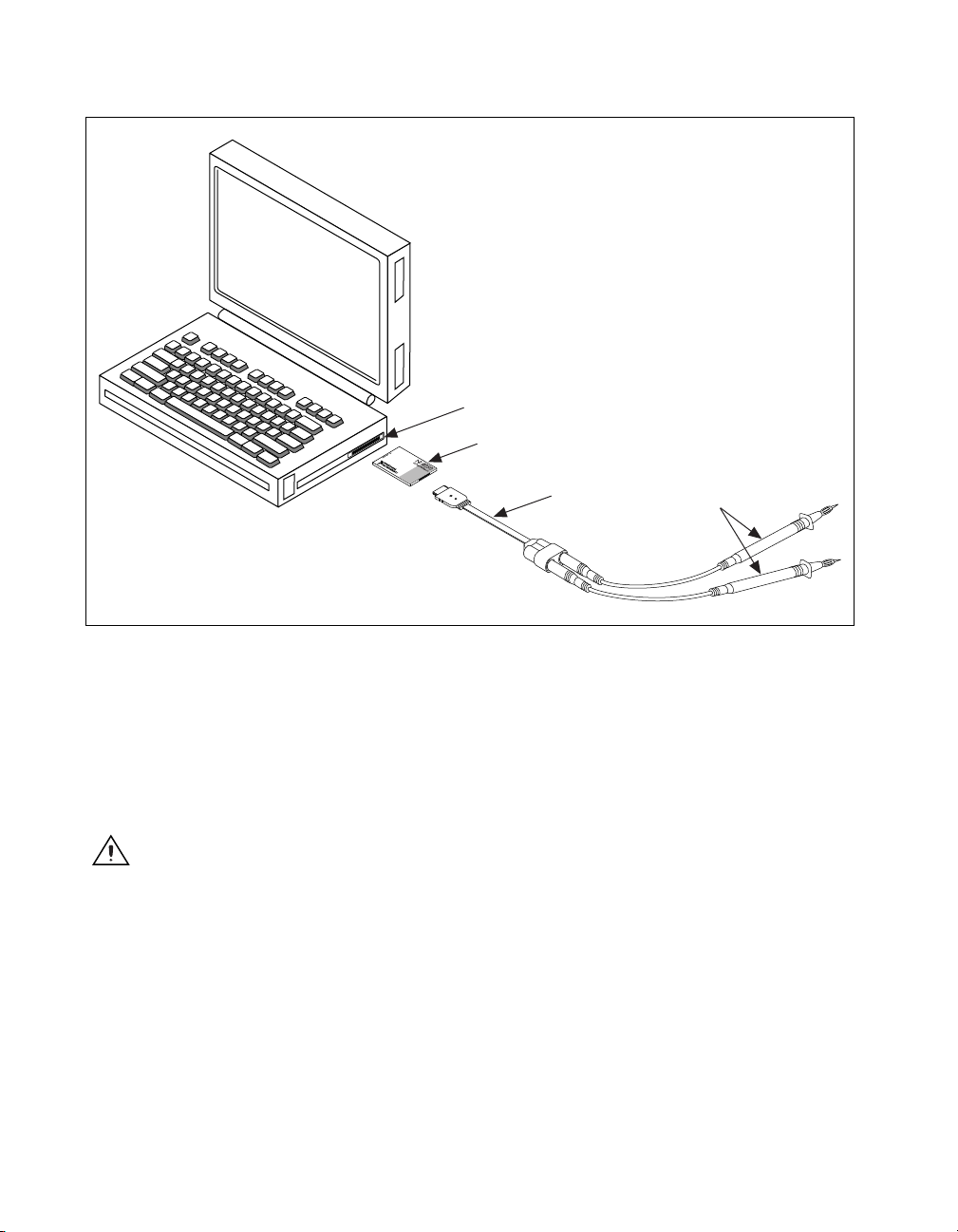
To use the NI 4050 accessory cable and probes with the NI 4050, first
connect the cable to the card as shown in Figure 1-1. The accessory cable
connector is polarized so that it cannot be plugged in incorrectly.
© National Instruments Corporation 1-1 NI 4050 User Manual
Page 10
Chapter 1 Taking Measurements with the NI 4050
Portable
Computer
PCMCIA Slot
NI 4050
Accessory Cable
Probes
Figure 1-1. Installing the NI 4050 and Cables
The test probes connect to the NI 4050 accessory cable via shrouded
banana jacks. The shrouds around the banana jacks prevent you from
contacting potentially hazardous voltages connected to the test probes.
Y ou can also connect the cable to standard, unshrouded banana jack probes
or accessories; however, use unshrouded probes or accessories only when
the voltages are less than 30 V
Caution To prevent possible safety hazards, the maximum voltage between either of the
inputs and the ground of the computer should never exceed ±250 VDC or 250 V
or 42 V
rms
pk-to-pk
.
.
rms
NI 4050 User Manual 1-2 www.ni.com
Page 11

Chapter 1 Taking Measurements with the NI 4050
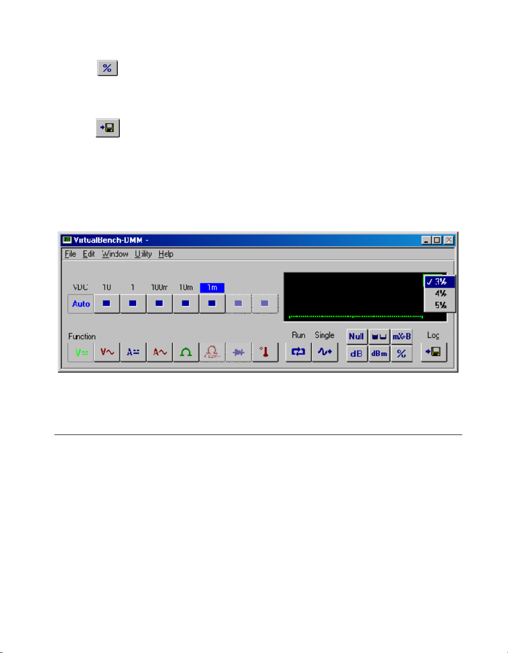
Introduction to the VirtualBench-DMM Soft Front Panel
The following sections explain how to make connections to your NI 4050
and take simple measurements using the VirtualBench-DMM, as shown in
Figure 1-2. To launch the soft front panel, select Start»Programs»
National Instruments DMM»Soft Front Panel.
Figure 1-2.
The following text describes the options available on the soft front panel.
Refer to Help»Online Reference located on the soft front panel for
information on front panel menus.
The range selector determines the range of measurements
V irtualBench-DMM makes. The range differs for each measurement mode.
If the measurement exceeds the range, +OVER or –OVER appears in the
measurement display. Auto selects the range that best matches the input
signal.
The value indicator displays the value measured by your NI 4060
(The value shown is an example only.).
The unit indicator displays the measurement units of the value you are
measuring. The units are expressed as VAC, VDC, mVAC, mVDC, Ω,
kΩ,MΩ, mA, AC, or mA DC. The indicator also displays the digits of
resolution. By clicking on the indicator, you can change the DMM’s
resolution.
NI-DMM Soft Front Panel
© National Instruments Corporation 1-3 NI 4050 User Manual
Page 12
Chapter 1 Taking Measurements with the NI 4050
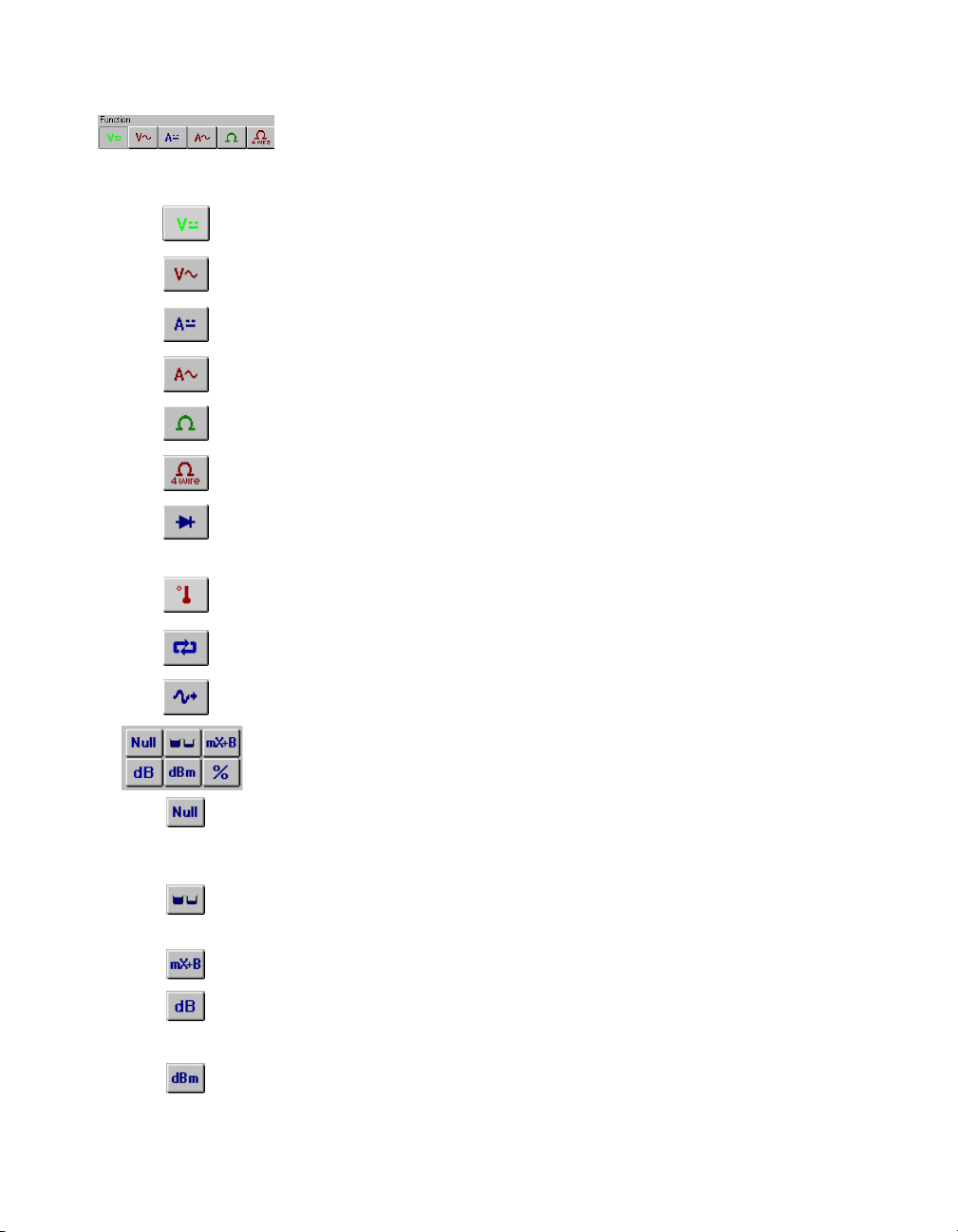
The Function selector allows you select a measurement mode. Select
Edit»Settings and click on the tabs for Current and Resistance or
Temperature to control the data type acquired by VirtualBench-DMM.
DC volts measures the DC component of a voltage signal.
AC volts measures the AC component of a voltage signal.
DC current measures the DC component of a current source.
AC current measures the AC component of a current source.
2-wire measures resistance using the 2-wire method.
4-wire measures resistance using the 4-wire method.
Diode measures the voltage drop across a diode. The maximum voltage
VirtualBench-DMM measures is 2 V.
Temperature measures temperature.
The run button starts and stops continuous DMM measurements.
The single button performs a single measurement.
The math buttons allow you to manipulate readings mathematically.
Null starts relative mode. VirtualBench-DMM makes all subsequent
measurements relative to the measurement it makes when you click
on Null.
Max/Min displays the maximum and minimum values that occur after you
start Relative mode.
mX+B enables the mX+B calculation on all readings.
dB compresses a large range of measurements into a much smaller range
by expressing DC or AC voltage in decibels.
dBm shows decibels above or below a 1 mW reference.
NI 4050 User Manual 1-4 www.ni.com
Page 13
Chapter 1 Taking Measurements with the NI 4050
% selects the percentage calculation. VirtualBench-DMM expresses the
displayed reading as a percent deviation from the reference value entered
in the Math Settings. Refer to Help»Online Reference, Math Settings topic
for more information about dB, dBm, mX+B, and percentage calculations.
The log button enables data logging. To configure the datalog file and log
interval, select Edit»Settings. Refer to Help»Online Reference, Logging
Measurements to Disk topic for more details.
Digits of Precision—A pop-up ring control in the DMM front panel display
allows you to set measurement accuracy to 3 1/2, 4 1/2, or 5 1/2. A larger
value gives greater precision but slower measurement performance. Refer
to Figure 1-3.
Figure 1-3. Digits of Precision
Use the Soft Front Panel
The following sections describe procedures for measuring DC and AC
voltage, resistance, diode, and temperature, using the soft front panel.
Measure DC and AC Voltage
Use the following procedure to measure DC and AC voltage using the soft
front panel:
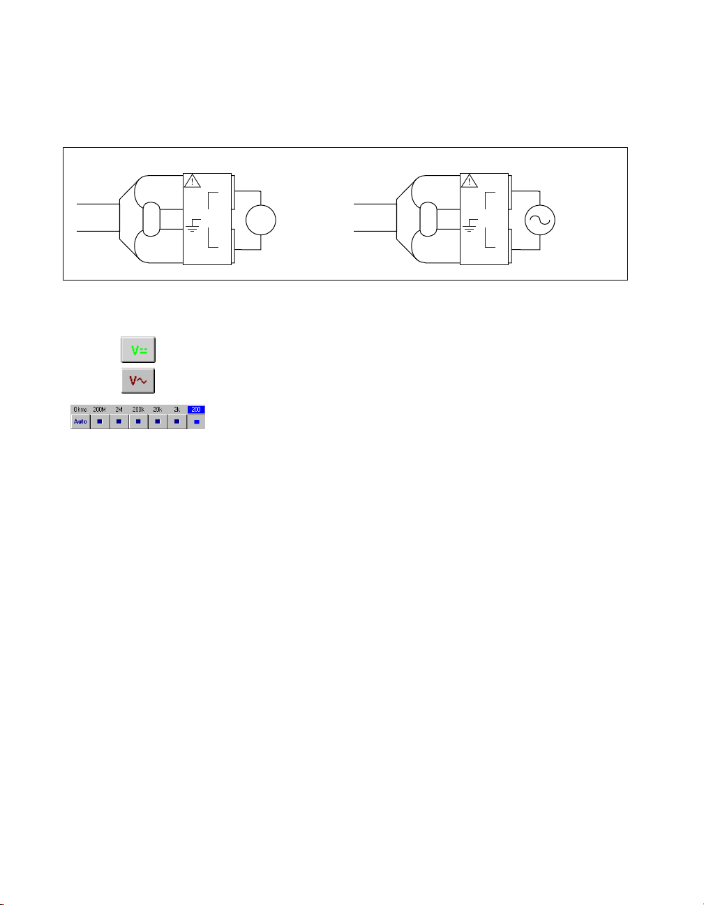
1. Connect the test probes to voltage signals as shown in Figure 1-4. For
DC voltages, the HI (red) terminal is the positive terminal, and the
LO (black) terminal is negative. For A C voltages, positive and ne gative
terms are irrelevant.
© National Instruments Corporation 1-5 NI 4050 User Manual
Page 14
Chapter 1 Taking Measurements with the NI 4050
The NI 4050 is protected against damage from voltages within
±250 VDC or 250 V
above these levels to the inputs.
in all ranges. You should never apply voltages
rms
HI
250 V
MAX.
+
–
LO
2. Select the mode you will measure:
•DC Volts
•AC Volts
3. Select the range for your measurement or autoranging:
• DC Volts—± 20 mV, ± 200 mV, ± 2 V, ± 25 V, and ± 250 V
• AC Volts—20 mV
The value indicator displays the voltage measured.
Measure 2-Wire Resistance
Use the following procedure to measure 2-wire resistance using the soft
front panel:
1. Connect the test probes to a resistor as shown in Figure 1-5. To
accurately measure the value of a resistor, mak e sure the resistor is not
connected to any other circuits. Erroneous or misleading readings may
result if the resistor you are measuring is connected to external circuits
that supply voltages or currents or to external circuits that change the
effective resistance of that resistor.
HI
DC Voltage
Source
250 V
MAX.
LO
Figure 1-4. Connecting Probes for Voltage Measurement
, 200 mV
rms
rms
, 2 V
rms
, 25 V
, and 250 V
rms
AC Voltage
Source
rms
NI 4050 User Manual 1-6 www.ni.com
Page 15

Chapter 1 Taking Measurements with the NI 4050
Figure 1-5. Connections for Resistance Measurement
2. Select 2-wire resistance mode.
3. Select the range for your measurement—200 Ω, 2 kΩ, 20 kΩ, 200 kΩ,
2 MΩ, 200 MΩ, or autorange.
The value indicator indicates the resistance measured. See the 2-Wire
Resistance Measurements section of Chapter 2, NI 4050 Operation, for
more information on 2-wire resistance measurements.
Measuring the Voltage Drop Across a Diode
The NI 4050 can excite a device under test and read the resulting voltage
drop. Diode mode is useful for testing diodes. Use the following procedure
to measure the forward drop across a diode. Voltage up to 2 V can be
measured in this mode.
1. Connect the test probes to a diode as shown in Figure 1-6. To
accurately measure the forward voltage of a diode, make sure that the
diode is not connected to any other circuits. The NI 4050 biases the
diode with a current of 100 µA and measures the resulting voltage
drop. Diode measurements are made with a fixed range of 2.0 V.
250 V
MAX.
HI
Resistor
LO
100 µA
HI
250 V
MAX.
+
Diode
–
LO
Figure 1-6. Connecting Signals for Diode Test
© National Instruments Corporation 1-7 NI 4050 User Manual
Page 16

Chapter 1 Taking Measurements with the NI 4050
2. Select diode mode.
3. Select the range for your measurement. Only the 2 V range is av ailable
for diode measurement.
The value indicator will indicate the voltage drop measured. If the display
indicates 2.200 VDC, the diode is either reverse biased or defectiv e. See the
Diode Measurements section of Chapter 2, NI 4050 Operation, for more
information on diode measurements.
Measure Current
You can use the NI 4050 to measure current with an optional National
Instruments CSM series current shunt module. These accessories are
connected between the NI 4050 cable and the test probes as shown in
Figure 1-7.
250 V
MAX.
HI
Current
Source
LO
Current Shunt
Accessory
Figure 1-7.
Connections for Current Measurement
Current shunt accessories contain a precision resistor that converts the
current through the shunt into a voltage that the NI 4050 can measure in
voltage mode. While the soft front panel cannot measure current directly
with the NI 4050, you can calculate the value of the current flowing through
the shunt by dividing the voltage measured by the value of the precision
resistor.
NI 4050 User Manual 1-8 www.ni.com
Page 17

Measure Temperature
You can measure temperature using common temperature transducers such
as resistive temperature devices (RTD) and thermistors. You can measure
transducers in the 2-wire resistance mode, as shown in Figure 1-8.
Although the soft front panel does not support temperature measurements,
you can convert and scale the transducer value to temperature
programmatically through software.
Note
The NI 4050 for PCMCIA does not support 4-wire resistance measurements. To
avoid measurement errors due to resistance offset, before doing resistance measurements,
measure the resistance to your loads.
Chapter 1 Taking Measurements with the NI 4050
HI
250 V
MAX.
LO
Resistor
Figure 1-8.
Connecting Signals for RTDs and Thermistors
© National Instruments Corporation 1-9 NI 4050 User Manual
Page 18

NI 4050 Operation
This chapter contains safety instructions, measurement fundamentals and
concerns, and scanning information.
Safety Instructions
2
Cautions
following:
Do not operate this instrument in an explosive atmosphere or where there may be
flammable gases or fumes.
Equipment described in this document must be used in an Installation Category II
environment per IEC 664. This category requires local level supply mains-connected
installation.
The NI 4050 must be used in a UL-listed laptop or personal computer.
To prevent safety hazards, the maximum voltage between either of the inputs and the
ground of the computer should never exceed ±250 VDC or 250 V
Do not operate damaged equipment. The safety protection features built into this
instrument can become impaired if the instrument becomes damaged in any way. If the
instrument is damaged, do not use it until service-trained personnel can check its safety.
If necessary, return the instrument to National Instruments for service and repair to ensure
that its safety is not compromised.
Do not operate this instrument in a manner that contradicts the information specified in this
document. Misuse of this instrument could result in a shock hazard.
Do not substitute parts or modify equipment. Because of the danger of introducing
additional hazards, do not install unauthorized parts or modify the instrument. Return the
instrument to National Instruments for service and repair to ensure that its safety is not
compromised.
Connections that exceed any of the maximum signal ratings on the NI 4050 can create a
shock or fire hazard or can damage any or all of the devices connected to the NI 4050.
National Instruments is not liable for any damages or injuries resulting from incorrect
signal connections.
Clean the instrument and accessories by brushing off light dust with a soft, nonmetallic
brush. Remove other contaminants with a stiff nonmetallic brush. The unit must be
completely dry and free from contaminants before returning to service.
To avoid personal injury or damage to electronic equipment, observe the
.
rms
© National Instruments Corporation 2-1 NI 4050 User Manual
Page 19

Chapter 2 NI 4050 Operation
Measurement Fundamentals
Warm Up
The required warm-up time for the NI 4050 is 30 minutes. This warm-up
time is important because measurements made with the NI 4050
multimeter can change with temperature. This change is called a thermal
drift and affects your accuracy. To minimize the effects of thermal drift and
ensure the specified accuracies, take all measurements after the NI 4050
has had a chance to fully warm up. Depending on your environment, the
NI 4050 can operate significantly above ambient temperature. Therefore,
measurements made immediately after powering up the system can differ
significantly from measurements made after the system has fully warmed
up. The NI 4050 temperature specifications are listed in the Accuracy
sections in Appendix A, Specifications.
Selecting the Resolution
The resolution on the NI 4050 multimeter is programmable. You can select
from three different resolutions: 5 1/2 digits, 4 1/2 digits, or 3 1/2 digits.
These settings allow you to trade off speed for resolution. The 5 1/2 digit
setting has the highest resolution and slowest reading rate, while the
3 1/2 digit setting gives you the least resolution and fastest reading rate.
Measurement mode and range affect the reading rate by requiring different
conversion times to obtain a given resolution for the different modes and
ranges.
Grounding
When measuring ground-referenced signals, connect the
ground-referenced side of your signal to the IN HI + terminal for best
performance.
Voltage Measurements
DC Voltage
Your NI 4050 multimeter uses a high-resolution delta sigma, A/D
converter (ADC) to sample signals and convert them into a digital form.
The ADC is preceded by a series of gain and attenuation circuitry that allow
both small and large signals to be measured using the same converter. The
NI 4050 uses a digital filter, which heavily rejects powerline frequencies
(50–60 Hz) and their harmonics, as well as high-frequency noise.
NI 4050 User Manual 2-2 www.ni.com
Page 20

Chapter 2 NI 4050 Operation
Input Ranges
The NI 4050 has five input ranges available for measuring DC voltages.
These ranges are ±20 mV, ±200 mV, ±2.0 V, ±25V, and ±250 V. Each
range has a 10% overrange, except for the 250 V range. The 250 V and
25 V input ranges have a 1 MΩ input impedance; the 2 V, 200 mV, and
20 mV ranges have an input impedance greater than 1 GΩ. Take these
values into consideration when measuring high-impedance sources. When
the NI 4050 is powered off, the 250 V and 25 V input range have a 1 MΩ
input impedance and the 2 V, 200 mV, and 20 mV ranges have an input
impedance of 100 kΩ.
If you are taking measurements that require a high degree of accuracy, you
should consider problems associated with input impedance, noise effects,
and thermal electromotive forces (thermal EMFs). These effects are
discussed in the Measurement Considerations section.
Measurement Considerations
Input Impedance
Figure 2-1 illustrates the input impedance of an NI 4050 and its effect on
the measurement of a circuit under test. If you know the source impedance
of the circuit being tested, you can correct for the attenuation caused by the
NI 4050 in software. Since R
source impedance, R
, to cause a large change in the measured voltage, Vm.
s
is large, at least 1 MΩ, it will require a large
in
External Source
Measured
Voltage
V
+
m
–
© National Instruments Corporation 2-3 NI 4050 User Manual
Input
Impedance
R
in
Figure 2-1.
VsR
--------------- ------------=
Rs+ R
in
in
V
m
Effect of Input Impedance on Signal Measurements
HI
Input
VΩ
LO
Impedance R
s
+
–
Source
Voltage V
s
Page 21

Chapter 2 NI 4050 Operation
Thermal EMF
Thermal EMFs, or thermoelectric potentials, are voltages generated at the
junctions of dissimilar metals and are functions of temperature. Thermal
EMFs in a circuit under test can cause higher than expected offsets that
change with temperature.
Noise Rejection
The NI 4050 filters out AC voltages in the DC voltage measurement
ranges. However, if the amplitudes of the AC voltages are large compared
to the DC voltages, or if the peak value (AC + DC) of the measured voltage
is outside the overrange limits, the NI 4050 may exhibit additional errors.
To minimize these errors, keep the NI 4050 away from strong AC magnetic
sources and minimize the area of the loop formed by the test leads.
Choosing the 5 1/2 digit resolution will also help minimize noise from
AC sources. If the peak value of the measured voltage is likely to exceed
the selected input range, select the next highest input range.
Normal Mode Rejection
Normal mode rejection (NMR) is the ability of the NI 4050 to reject a
normally (differentially) applied signal. The ability is quantified in the
normal mode rejection ratio (NMRR) specification, which indicates the
capability of the NI 4050 to reject 50 or 60 Hz and is valid only at the
specified frequency and useful only when taking DC measurements. The
NMRR is specified at the powerline frequency because this is typically
where most measurement noise occurs.
Figure 2-2 shows a 60 Hz signal connected differentially to the NI 4050 in
DC Volts mode. V
is the voltage that will be measured after the signal is
m
rejected. NMR is very useful when trying to measure DC voltages in the
presence of large powerline interference.
NI 4050 User Manual 2-4 www.ni.com
Page 22

Chapter 2 NI 4050 Operation
HI
Measured
Voltage
V
+
m
–
VmV
VΩ
LO
×=
10
s
Input
–
NMRR
--------------------
20
Source
Voltage
V
s
at 60 Hz
Figure 2-2. Normal Mode Measurement Effects
If you are measuring signals in the presence of large normal mode voltages,
consult Appendix A, Specifications, to calculate the additional error to your
system. Use the equation in Figure 2-2 to calculate the voltage error due to
normal mode voltage.
Common Mode Rejection
Common mode rejection (CMR) is the ability of the NI 4050 to reject
signals that are common to both input terminals. The ability is quantified in
the common mode rejection ratio (CMRR) specification. Theoretically, the
floating measurement circuitry of the NI 4050 should have an infinite
CMRR. Parasitic resistances and capacitances to earth ground limit the
CMR of the NI 4050. This effect is most noticeable when measuring small
signals in the presence of a large common mode voltage, as shown in
Figure 2-3.
© National Instruments Corporation 2-5 NI 4050 User Manual
Page 23

Chapter 2 NI 4050 Operation
HI
Measured
Voltage
V
+
m
–
V
V
error
----- -
VmVsV
Input
VΩ
LO
–
CMRR
--------------------
s
+
V
c
2
20
10
×=
+=
error
+
–
+
–
Source
Voltage
V
s
Common
Voltage
V
c
Figure 2-3. Common Mode Measurement Effects
Using the equation in Figure 2-3, you can calculate the voltage error due to
the common mode voltage. If you are measuring signals in the presence of
large common mode voltages, consult Appendix A, Specifications, to
calculate the additional error to your system.
Effective Common Mode Rejection
Effective common mode rejection is the sum of the CMRR and the NMRR
at a given frequency. It is the effective rejection on a given noise signal that
is applied to both input leads as it gets rejected first by the CMR capability
of the instrument then again by its NMR capability. This specification is
most useful at the powerline frequency where most of the noise resides and
is only valid for DC measurements.
AC Voltage
In the AC voltage ranges, the NI 4050 measures the AC-coupled RMS
value of a signal. The RMS value of a signal is a fundamental measurement
of the magnitude of an AC signal. The RMS value of an AC signal can be
defined mathematically as the square root of the average of the square of
the signal.
In practical terms, the RMS value of an AC signal is the DC v alue required
to produce an equivalent amount of heat in the same resistive load. The
NI 4050 first AC-couples the measured signal to remove any DC
NI 4050 User Manual 2-6 www.ni.com
Page 24

Chapter 2 NI 4050 Operation
components and then measures the RMS value of the A C component. This
method lets you measure a small AC signal in the presence of a large DC
offset.
Input Ranges
The NI 4050 has five input ranges available for measuring AC voltages.
These ranges are 20 mV
The impedance in each of these ranges is a 0.068 µF capacitor followed by
1 MΩ. When the NI 4050 is powered off, the 250 V, 25 V, and 2 V input
ranges have a 0.068 µF capacitor, followed by a 1 MΩ input impedance.
The 200 mV and 20 mV ranges have a 0.068 µF capacit or, followed by
an approximate 100 kΩ input impedance.
The NI 4050 can measure AC voltages to its specif ied accuracy as long as
the voltage is at least 10% and no more than 100% of the selected input
range. The DC component in any of these ranges can be as high as
250 VDC. Each range, except for the 250 V range, has a 10% overrange.
The AC volta ge measurement accuracy depends on many factors, including
the signal amplitude, frequency, and waveform shape.
, 200 mV
rms
rms
, 2.0 V
rms
, 25 V
, and 250 V
rms
rms
.
Measurement Considerations
AC Offset Voltage
The AC measurements of the NI 4050 are specified over the range of 10%
to 100% of the full-scale input range. Below 10% of the input range, errors
due to the AC voltage offset become significant. This offset, unlike DC
voltage offsets, cannot simply be subtracted from the readings or zeroed out
because the offset gets converted in the RMS conversion. To minimize the
errors due to the AC offset voltage, choose an input range that keeps the
measured voltage between 10% and 100% of full scale.
Frequency Response
The accuracy of the NI 4050’s AC voltage measurements is a function of
the input signal frequency. Your NI 4050 is calibrated at the factory using
a 1 kHz sine wave. Your frequency-dependent error will be minimal around
this frequency. The error will then increase as you approach the upper and
lower bandwidth limits. This additional error is added to the accuracy
errors in computing the absolute error.
© National Instruments Corporation 2-7 NI 4050 User Manual
Page 25

Chapter 2 NI 4050 Operation
These additional errors are shown in Appendix A, Specifications. While the
NI 4050 is characterized and specified over the 20 Hz to 25 kHz frequency
range, measurements outside of this range can still be made with decreased
accuracy .
Resistance Measurements
2-Wire Resistance Measurements
The NI 4050 measures 2-wire resistance by passing a current through the
device under test and reading the resulting voltage drop through the same
connections, as illustrated in Figure 2-4. The resistance value is then
computed using Ohm’s Law (R=V/I). To accurately measure the value of
a resistor, make sure the resistor is not connected to any other circuits.
Erroneous or misleading readings can result if the resistor you are
measuring is connected to external circuits that supply voltages or currents,
or to external circuits that change the effective resistance of that resistor.
+
V
sense
–
I
ex
HI
I
ex
Input
VΩ
LO
R
unknown
I
ex
V
R
unknown =
I
= 100 µA (200 Ω, 2 kΩ, 20 kΩ ranges)
ex
Figure 2-4.
sense
I
ex
1 µA (200 kΩ, 2 MΩ, 200 MΩ ranges)
Circuit for 2-Wire Resistance Measurements
Input Ranges
The NI 4050 has five basic input ranges for 2-wire resistance as well as an
extended range. The basic ranges are 200 Ω, 2.0 kΩ, 20 kΩ, 200 kΩ, and
2 MΩ. With the extended range, measurements up to at least 200 MΩ are
possible.
NI 4050 User Manual 2-8 www.ni.com
Page 26

In the extended ohms range, the NI 4050 adds a 1 MΩ resistor in parallel
with the test resistor, and then calculates the value of the resistor being
tested. The test current for the 200 Ω, 2.0 kΩ, and 20 kΩ ranges is 100 µA.
The test current for the 200 kΩ, 2 MΩ, and 200 MΩ ranges is 1 µA.
Continuity Measurements
Many traditional multimeters can take continuity measurements, which test
for the presence or absence of continuity between the two test probes.
These measurements are simply resistance measurements, where the
resistance between the two probes is measured and compared to a set value.
You can perform continuity measurements on a circuit by setting the
NI 4050 to the 200 Ω range and comparing the measured value to some low
resistance value, typically 10 Ω. If the measured value is less than 10 Ω,
there is continuity between the test probes.
Diode Measurements
To properly measure the forward voltage of a diode, make sure that the
diode is not connected to any other circuits. The NI 4050 biases the diode
with a current of 100 µA and measures the resulting voltage drop, as
illustrated in Figure 2-5. Diode measurements are made with a fixed range
of 2.0 V.
Chapter 2 NI 4050 Operation
Note
Different multimeters use different currents to excite the diode. This may result in
different readings for the same diode.
I
HI
+
V
sense
–
Figure 2-5.
© National Instruments Corporation 2-9 NI 4050 User Manual
I
ex
Circuit for Diode Measurements
Input
VΩ
LO
ex
+
V
diode
–
I
ex
V
= V
sense
diode
Page 27

Specifications
This appendix lists the specifications of the NI 4050. These specifications
are guaranteed between 15 and 35 °C unless otherwise specified.
DC Voltage
Accuracy (% of reading ± µV)
A
24 Hour
Range
250.000 V 0.0032% ± 4.9 mV 0.021% ± 49 mV 0.024% ± 49 mV 0.0017% ± 4800 µV
25.0000 V 0.0032% ± 4.9 mV 0.021% ± 49 mV 0.024% ± 49 mV 0.0017% ± 4800 µV
2.00000 V 0.0029% ± 37 µV 0.014% ± 260 µV 0.017% ± 260 µV 0.0009% ± 25 µV
200.000 mV 0.0029% ± 27 µV 0.014% ± 250 µV 0.017% ± 250 µV 0.0009% ± 25 µV
20.0000 mV 0.0029% ± 27 µV 0.014% ± 250 µV 0.017% ± 250 µV 0.0009% ± 25 µV
Accuracy numbers are for 5 1/2 digits and include the effects of full-scale and zero-scale errors, temperature variation,
linearity, and noise.
(25 °C ± 1 °C)
90 Day
(25 °C ± 10 °C)
1 Year
(25° C ± 10 °C)
Temperature Coefficient
(% of Reading/ °C ± µV/ °C)
Noise Rejection
NMRR (10 Hz reading rate, 50/60 Hz
powerline frequency ±1%)..................... 80 dB
DC ECMRR...........................................140 dB (with a 1 kΩ imbalance
in LO lead)
AC ECMR (RDC to 60 Hz)...................150 dB (with a 1 kΩ imbalance
in LO lead)
Input Characteristics
Input bias current ...................................1 nA max
Input resistance ......................................> 1 GΩ (2 V, 200 mV,
20 mV ranges);
1MΩ (250 V, 25 V)
© National Instruments Corporation A-1 NI 4050 User Manual
Page 28

Appendix A Specifications
DC Current
Accuracy (% of reading ± µA
)
DC current measurements require the use of the CSM current shunt
modules.
24 Hour
Range
200.000 mA
20.0000 mA
10.0000 A
Accuracy numbers are for 5 1/2 digits and include the effects of full-scale and zero-scale errors, temperature variation,
linerarity, and noise.
*
Requires 200 mA shunt, CSM-200mA.
**
Requires 10 A shunt, CSM-10A.
(25 °C ± 1 °C)
*
0.1% ± 27 µA 0.14% ± 250 µA 0.15% ± 250 µA 0.0035% ± 25 µA
*
0.1% ± 27 µA 0.14% ± 250 µA 0.15% ± 250 µA 0.0035% ± 25 µA
**
0.02% ± 4 mA 0.035% ± 26 mA 0.035% ± 26 mA 0.007% ± 2.5 mA
90 Day
(25 °C ± 10 °C)
1 Year
(25 °C ± 10 °C)
Temperature Coefficient
(% of Reading/°C ± µA/°C
Input Characteristics
200 mA shunt
Input protection ...............................Fuse F1 500 mA/250 V fast
fusing
Shunt resistor...................................1 Ω
Burden voltage.................................< 400 mV at 200 mA
10 A shunt
Input protection ...............................Fuse F1 12.5 A/250 V fast fusing
Shunt resistor...................................10 mΩ
Burden voltage.................................< 300 mV at 10 A
)
NI 4050 User Manual A-2 www.ni.com
Page 29

AC Voltage
Appendix A Specifications
Accuracy (% of reading ± mV)
24 Hour
Range
250.000 V 0.6% ± 500 mV 0.62% ± 680 mV 0.62% ± 680 mV 0.007% ± 20 mV
25.0000 V 0.3% ± 30 mV 0.32% ± 210 mV 0.32% ± 210 mV 0.007% ± 20 mV
2.00000 V 0.4% ± 3 mV 0.42% ± 21 mV 0.42% ± 21 mV 0.019% ± 2 mV
200.000 mV 0.3% ± 0.22 mV 0.32% ± 1.20 mV 0.32% ± 1.20 mV 0.007% ± 0.110 mV
20.0000 mV 0.4% ± 100 µV 0.42% ± 170 µV 0.42% ± 170 µV 0.019% ± 12 µV
Accuracy numbers are for 5 1/2 digits and include the effects of full-scale and zero-scale errors, temperature variation,
linerarity, and noise, applies for sine waves ≥ 10% of input range. Accuracy may be affected by source impedance, cable
capacitances dielectric absorption, or slew rate.
(25 °C ± 1 °C)
90 Day
(25 °C ± 10 °C)
1 Year
(25 °C ± 10 °C)
Tempe rature Coefficient
(% of Reading/°C ± mV/°C
Noise Rejection
AC CMRR (DC to 60 Hz)......................> 80 dB (with a 1 kΩ imbalance
in LO lead)
Input Characteristics
Input resistance ......................................1 MΩ all ranges
Bandwidth..............................................20 Hz–25 kHz
Additional AC Errors
Frequency-dependent errors
)
Input Frequency Additional Error (% of Reading)
20–50 Hz 2.5%
50–100 Hz 1%
100 Hz–5 kHz 0%
5–10 kHz 1%
10–25 kHz 2.5%
© National Instruments Corporation A-3 NI 4050 User Manual
Page 30

Appendix A Specifications
AC Current
Accuracy (% of reading ± mA)
AC current measurements require the use of the CSM current shunt
module.
24 Hour
Range
200.000 mA
20.0000 mA
10.0000 A
Accuracy numbers are for 5 1/2 digits and include the effects of full-scale and zero-scale errors, temperature variation,
linerarity, and noise.
*
Requires 200 mA shunt, CSM-200mA.
**
Requires 10 A shunt, CSM-10A.
(25 °C ± 1 °C)
*
0.45% ± 0.22 mA 0.47% ± 1.2 mA 0.47% ± 1.2 mA 0.007% ± 0.110 mA
*
0.35% ± 110 µA 0.37% ± 170 µA 0.37% ± 170 µA 0.019% ± 0.120 mA
**
0.3% ± 22 mA 0.32% ± 120 mA 0.32% ± 120 mA 0.026% ± 11 mA
90 Day
(25 °C ± 10 °C)
1 Year
(25 °C ± 10 °C)
Temperature Coefficient
(% of Reading/°C ± mA/°C)
Input Characteristics
200 mA shunt
Input protection ...............................Fuse F1 500 mA/250 V fast
fusing
Shunt resistor...................................1 Ω
Burden voltage.................................< 400 mV at 200 mA
10 A shunt
Input protection ...............................Fuse F1 12.5 A/250 V fast fusing
Shunt resistor...................................10 mΩ
Burden voltage.................................< 300 mV at 10 A
NI 4050 User Manual A-4 www.ni.com
Page 31

Resistance
Appendix A Specifications
Accuracy (% of reading ± Ω)
24 Hour
Range
Extended Ohm
(> 2 M
Ω)
2.00000 M
200.000 k
20.0000 k
2.00000 k
200.000
Accuracy numbers are for 5 1/2 digits and include the effects of full-scale and zero-scale errors, temperature variation,
linearity, and noise.
Ω
Ω
Ω
Ω
Ω
(25 °C ± 1 °C)
0.1% ± 6 k
0.012% ± 55
0.012% ± 37
0.006% ± 0.5
0.006% ± 0.4
0.006% ± 0.4
Ω
Ω
Ω
Ω
Ω
Ω
90 Day
(25 °C ± 10 °C)
0.1% ± 60 k
0.077% ± 370
0.077% ± 350
0.024% ± 4
0.024% ± 4
0.024% ± 4
1 Year
(25 °C ± 10 °C)
Ω
Ω
Ω
Ω
Ω
Ω
0.1% ± 60 k
0.080% ± 20
0.080% ± 2
0.027% ± 4
0.027% ± 4
0.027% ± 4
Ω
Ω
Ω
Ω
Ω
Ω
Temperature Coefficient
(% of Reading/°C ±
0.0072% ± 6 k
0.0072% ± 35
0.0072% ± 35
0.0020% ± 0.40
0.0020% ± 0.40
0.0020% ± 0.40
Measurement mode................................2-wire Ohms
Test current ............................................ 100 µA for 200 Ω, 2 kΩ,
20 kΩ ranges
1 µA for 2 MΩ, 200 kΩ ranges
1 µA and 1 MΩ in parallel for
extended Ohms mode
Diode Testing
Accuracy (% of reading ± µV)
/°C)
ΩΩΩΩ
Ω
Ω
Ω
Ω
Ω
Ω
24 Hour
Range
2 V 0.006% ± 60 µV 0.024% ± 400 µV 0.027% ± 400 µV 0.002% ± 40 µV
Accuracy numbers are for 5 1/2 digits and include the effects of full-scale and zero-scale errors, temperature variation,
linearity, and noise.
(25 °C ± 1 °C)
90 Day
(25 °C ± 10 °C)
1 Year
(25 °C ± 10 °C)
Temperature Coefficient
(% of Reading/°C ± µV/°C)
Test current ................................... .........100 µA
© National Instruments Corporation A-5 NI 4050 User Manual
Page 32

Appendix A Specifications
General Specifications
Settling time............................................Affected by source impedance
Warm-up time.........................................30 minutes for measurements
Bus type..................................................PCMCIA, slave
Altitude.................................................. .Up to 2,000 m; at higher altitudes
Working voltage .....................................250 V maximum between either
Power requirement..................................+5 VDC, 45 mA in operational
Safety......................................................Designed in accordance with
and input signal changes
accurate within specifications
the installation category must be
derated
input terminal and earth ground
mode
IEC 1010-1 and UL 3 111 for
electrical measuring and testing
equipment,
Installation Category II,
Pollution Degree 2,
Double Insulated,
Indoor use,
UL 3111 listed
Physical
Dimensions.............................................Type II PC Card
Environment
Operating temperature............................0 to 55 °C
Storage temperature................................–20 to 70 °C
Relative humidity ...................................10% to 90% noncondensing
NI 4050 User Manual A-6 www.ni.com
Page 33

Technical Support Resources
This appendix describes the comprehensive resources available to you in
the Technical Support section of the National Instruments Web site and
provides technical support telephone numbers for you to use if you have
trouble connecting to our Web site or if you do not have internet access.
NI Web Support
To provide you with immediate answers and solutions 24 hours a day,
365 days a year, National Instruments maintains extensi ve online technical
support resources. They are available to you at no cost, are updated daily,
and can be found in the Technical Support section of our Web site at
www.ni.com/support.
Online Problem-Solving and Diagnostic Resources
• KnowledgeBase—A searchable database containing thousands of
frequently asked questions (F A Qs) and their corresponding answers or
solutions, including special sections devoted to our newest products.
The database is updated daily in response to new customer experiences
and feedback.
• Troubleshooting Wizards—Step-by-step guides lead you through
common problems and answer questions about our entire product line.
Wizards include screen shots that illustrate the steps being described
and provide detailed information ranging from simple getting started
instructions to advanced topics.
• Product Manuals—A comprehensive, searchable library of the latest
editions of National Instruments hardware and software product
manuals.
• Hardware Reference Database—A searchable database containing
brief hardware descriptions, mechanical drawings, and helpful images
of jumper settings and connector pinouts.
• Application Notes—A library with more than 100 short papers
addressing specific topics such as creating and calling DLLs,
developing your own instrument driver software, and porting
applications between platforms and operating systems.
B
© National Instruments Corporation B-1 NI 4050 User Manual
Page 34

Appendix B Technical Support Resources
Software-Related Resources
• Instrument Driver Network—A library with hundreds of instrument
drivers for control of standalone instruments via GPIB, VXI, or serial
interfaces. You also can submit a request for a particular instrument
driver if it does not already appear in the library.
• Example Programs Database—A database with numerous,
non-shipping example programs for National Instruments
programming environments. You can use them to complement the
example programs that are already included with National Instruments
products.
• Software Library—A library with updates and patches to application
software, links to the latest versions of driver software for National
Instruments hardware products, and utility routines.
Worldwide Support
National Instruments has offices located around the globe. Many branch
offices maintain a Web site to provide information on local services. You
can access these Web sites from
www.ni.com/worldwide
If you have trouble connecting to our Web site, please contact your local
National Instruments office or the source from which you purchased your
National Instruments product(s) to obtain support.
For telephone support in the United States, dial 512 795 8248. For
telephone support outside the United States, contact your local branch
office:
Australia 03 9879 5166, Austria 0662 45 79 90 0, Belgium 02 757 00 20,
Brazil 011 284 5011, Canada (Calgary) 4 03 274 9391,
Canada (Ontario) 905 785 0085, Canada (Québec) 514 694 8521,
China 0755 3904939, Denmark 45 76 26 00, Finland 09 725 725 11,
France 01 48 14 24 24, Germany 089 741 31 30, Greece 30 1 42 96 427,
Hong Kong 2645 3186, India 91805275406, Israel 03 6120092,
Italy 02 41309 1, Japan 03 5472 2970, Korea 02 596 7456,
Mexico (D.F.) 5 280 7625, Mexico (Monterrey) 8 357 7695,
Netherlands 0348 433466, New Zealand 09 914 0488,
Norway 32 27 73 00, Poland 0 22 528 94 06, Portugal 351 1 726 9011,
Singapore 2265886, Spain 91 640 0085, Sweden 08 587 895 00,
Switzerland 056 200 51 51, Taiwan 02 2528 7227,
United Kingdom 01635 523545
NI 4050 User Manual B-2 www.ni.com
Page 35

Glossary
Prefix Meanings Value
p- pico- 10
n- nano- 10
µ- micro- 10
m- milli- 10
k- kilo- 10
M- mega- 10
G- giga- 10
Numbers/Symbols
% percent
+ positive of, or plus
– negative of, or minus
–12
–9
–6
–3
3
6
9
/per
°degree
± plus or minus
Ω ohm
A
A amperes
AC alternating current
AC coupled the passing of a signal through a filter network that removes the
DC component of the signal
A/D analog-to-digital
© National Instruments Corporation G-1 NI 4050 User Manual
Page 36

Glossary
ADC analog-to-digital converter—an electronic device, often an integrated
circuit, that converts an analog voltage to a digital number
ADC resolution the resolution of the ADC, which is measured in bits. An ADC with16 bits
has a higher resolution, and thus a higher degree of accuracy, than a
12-bit ADC.
ADE Application Development Environment
amplification a type of signal conditioning that improves accuracy in the resulting
digitized signal and reduces noise
amplitude flatness a measure of how close to constant the gain of a circuit remains over a range
of frequencies
aperture time the period of time over which a measurement is averaged; also called the
number of powerline cycles
attenuate
autozero technique of internally shorting the internal circuit while disconnecting the
to reduce in magnitude
measurement to compensate for temperature effects
B
b bit—one binary digit, either 0 or 1
B byte—eight related bits of data, an eight-bit binary number. Also used to
denote the amount of memory required to store one byte of data.
bus the group of conductors that interconnect individual circuitry in a computer.
Typically, a bus is the expansion veh icle to wh ich I/O or other devices are
connected. Examples of PC buses are the PCI and ISA bus.
burden voltage the voltage drop across the input section of the current mode
C
C Celsius
CMRR common-mode rejection ratio—a measure of an instrument’s ability to
reject interference from a common-mode signal, usually expressed in
decibels (dB)
NI 4050 User Manual G-2 www.ni.com
Page 37

Glossary
CompactPCI refers to the core specification defined by the PCI Industrial Computer
Manufacturer’s Group (PICMG)
conversion device device that transforms a signal from one form to another. For example,
analog-to-digital converters (ADCs) for analog input, digital-to-analog
converters (DACs) for analog output, digital input or output ports, and
counter/timers are conversion devices.
conversion time the time required, in an analog input or output system, from the moment a
channel is interrogated (such as with a read instruction) to the moment that
accurate data is available
coupling the manner in which a signal is connected from one location to another
CPU central processing unit
crest factor the ratio of the peak value of the signal to the RMS value of the signal
CSM current shunt module
D
DAQ data acquisition—(1) collecting and measuring electrical signals from
sensors, transducers, and test probes or fixtures and inputting them to a
computer for processing; (2) collecting and measuring the same kinds of
electrical signals with A/D and/or DIO boards plugged into a computer , and
possibly generating control signals with D/A and/or DIO boards in the
same computer
dB decibel—the unit for expressing a logarithmic measure of the ratio of two
signal levels: dB=20log10 V1/V2, for signals in volts
DC direct current
default setting a default parameter value recorded in the driver. In many cases, the default
input of a control is a certain value (often 0) that means use the current
default setting.
device a plug-in data acquisition board, card, or pad that can contain multiple
channels and conversion devices. Plug-in boards, PCMCIA cards,
devices such as the DAQPad-1200, which connects to your computer
parallel port, are all examples of DAQ devices.
© National Instruments Corporation G-3 NI 4050 User Manual
Page 38

Glossary
dielectric absorption a parasitic phenomenon related to capacitors that can cause unexpectedly
long settling times in circuits using capacitors with poor dielectric
absorption specifications
differential input an analog input consisting of two terminals, both of which are isolated from
computer ground, whose difference is measured
DMM digital multimeter
DNL differential nonlinearity—a measure in LSB of the worst-case deviation of
code widths from their ideal value of 1 LSB
double insulated a device that contains the necessary insulating structures to pro vide electric
shock protection without the requirement of a safety ground connection
drivers software that controls a specific hardware instrument
E
ECMR Effective Common Mode Rejection—a measure of an instrument’s ability
to reject interference from a common-mode signal. This includes both the
effects of normal mode rejection and common mode rejection.
EEPROM electrically erasable programmable read-only memory—ROM that can be
erased with an electrical signal and reprogrammed
EXT TRIG IN external trigger input signal
F
F farads
filtering a type of signal conditioning that allows you to filter unwanted signals from
the signal you are trying to measure
G
gain the factor by which a signal is amplified, sometimes expressed in decibels
NI 4050 User Manual G-4 www.ni.com
Page 39

Glossary
H
harmonics multiples of the fundamental frequency of a signal
half-power bandwidth the frequency range ov er which a circuit maintains a level of at least –3 dB
with respect to the maximum level
hardware the physical components of a computer system, such as the circuit boards,
plug-in boards, chassis, enclosures, peripherals, cables, and so on
Hz hertz—per second, as in cycles per second or samples per second
I
I
ex
IEC International Electrotechnical Commission
IEEE Institute of Electrical and Electronics Engineers
in. inches
inductance the relationship of induced voltage to current
input bias current the current that flow s into the inputs of a circuit
input impedance the measured resistance and capacitance between the input terminals of a
Installation Category
(Overvoltage Category)
instrument driver a set of high-level software functions that controls a specific plug-in DAQ
interrupt a computer signal indicating that the CPU should suspend its current task
interrupt level the relative priority at which a device can interrupt
excitation current
circuit
classification system for expected transients on electrical supply
installations
board. Instrument drivers are available in several forms, ranging from a
function callable language to a virtual instrument (VI) in LabVIEW.
to service a designated activity
I/O input/output—the transfer of data to/from a computer system involving
communications channels, operator interface devices, and/or data
acquisition and control interfaces
© National Instruments Corporation G-5 NI 4050 User Manual
Page 40

Glossary
ISA industry standard architecture
isolation a type of signal conditioning in which you isolate the transducer signals
from the computer for safety purposes. This protects you and your
computer from large voltage spikes and mak es sure the measurements from
the DAQ device are not affected by differences in ground potentials.
isolation voltage the voltage that an isolated circuit can normally withstand, usually
specified from input to input and/or from any input to the amplifier output,
or to the computer bus
M
m meters
MB megabytes of memory
N
NI-DAQ National Instruments driver software for DAQ hardware.
NMRR normal mode rejection ratio—a measure of an instrument’ s ability to reject
a signal applied directly to the differential inputs of the instrument
noise an undesirable electrical signal—Noise comes from external sources such
as the AC po wer line, motors, generators, transformers, fluorescent lights,
soldering irons, CR T displays, computers, electrical storms , welders, radio
transmitters, and internal sources such as semiconductors, resistors, and
capacitors. Noise corrupts signals you are trying to send or receive.
O
Ohm’s Law (R=V/I)—the relationship of voltage to current in a resistance
overrange a segment of the input range of an instrument outside of the normal
measuring range. Measurements can still be made, usually with a
degradation in specifications.
NI 4050 User Manual G-6 www.ni.com
Page 41

Glossary
P
PCI Peripheral Component Interconnect—a high-performance expansion bus
architecture originally developed by Intel to replace ISA and EISA; it is
achieving widespread acceptance as a standard for PCs and workstations
and offers a theoretical maximum transfer rate of 132 Mbytes/s
peak value the absolute maximum or minimum amplitude of a signal (AC + DC)
PXI PCI eXtensions for Instrumentation. PXI is an open specification that
builds off the CompactPCI specification by adding
instrumentation-specific features.
R
Rresistor
RAM random-access memory
range error an error in accuracy that is determined by the input range that is selected.
The range error is independent of the value of the signal being measured.
reading error an error in accuracy that is determined by the input range, as well as the
value being measured
reading rate the rate at which a new measurement is taken. In addition to the
measurement speed, the selection of the reading rate affects the filtering,
and thus the noise level, of measurements.
resolution the smallest signal increment that can be detected by a measurement
system. Resolution can be expressed in bits or in digits. The number of bits
in a system is roughly equal to 3.3 times the number of digits.
rms root mean square—a measure of signal amplitude; the square root of the
average value of the square of the instantaneous signal amplitude
ROM read-only memory
R
sense
© National Instruments Corporation G-7 NI 4050 User Manual
the sense resistor. The vo ltage across this resistor is measured and
converted to a current.
Page 42

Glossary
S
s seconds
S samples
sense in four-wire resistance the sense measures the voltage across the resistor
being excited by the excitation current
settling time the amount of time required for a voltage to reach its final value within
specified limits
S/s samples per second—used to express the rate at which an instrument
samples an analog signal
system noise a measure of the amount of noise seen by an analog circuit or an ADC when
the analog inputs are grounded
T
temperature
coefficient
thermal drift measurements that change as the temperature varies
thermoelectric
potentials
thermal EMFs thermal electromotive forces—voltages generated at the junctions of
transfer rate the rate, m easured in bytes/s, at which data is moved from source to
the percentage that a measurement will vary according to temperature.
See also thermal drift
See thermal EMFs
dissimilar metals that are functions of temperature. Also called
thermoelectric potentials.
destination after software initialization and set up operations; the maximum
rate at which the hardware can operate
U
UL Underwriters Laboratory
NI 4050 User Manual G-8 www.ni.com
Page 43

V
V volts
VAC volts alternating current
VDC volts direct current
Glossary
V
error
voltage error
VI virtual instrument—(1) a combination of hardware and/or software
elements, typically used with a PC, that has the functionality of a classic
stand-alone instrument (2) a LabVIEW software module (VI), which
consists of a front panel user interface and a block diagram program
VMC voltmeter complete signal
V
V
rms
sense
volts, root mean square value
the voltage that is created across the device under test when excited by a
current
W
waveform shape the shape the magnitude of a signal creates over time
working voltage the highest voltage that should be applied to a product in normal use,
normally well under the breakdown voltage for safety margin
© National Instruments Corporation G-9 NI 4050 User Manual
Page 44

Index
A
AC current specifications, A-4
AC voltage measurement, 2-6 to 2-8
AC offset voltage, 2-7
frequency response, 2-7 to 2-8
input ranges, 2-7
using VirtualBench-DMM Soft Front
panel, 1-5 to 1-6
AC voltage specifications, A-3
C
cables and probes, 1-1 to 1-2
installing, 1-1 to 1-2
overview, 1-1
common mode rejection, 2-6 to 2-7
continuity measurements, 2-9
conventions used in manual, vi
current measurement, 1-8
D
DC current specifications, A-2
DC voltage measurement, 2-2 to 2-6
common mode rejection, 2-6 to 2-7
effective common mode rejection, 2-6
input impedance, 2-3
input ranges, 2-3
noise rejection, 2-4 to 2-6
normal mode rejection, 2-4 to 2-5
thermal EMF, 2-4
using VirtualBench-DMM Soft Front panel,
1-5to1-6
DC voltage specifications, A-1
diagnostic resources, online, B-1
diode measurement
circuit (figure), 2-9
description, 2-9
using VirtualBench-DMM Soft Front
panel, 1-7 to 1-8
diode testing specifications, A-5
E
effective common mode rejection, 2-6
environment specifications, A-6
F
frequency response, AC voltage
measurement, 2-7 to 2 -8
G
grounding the NI 4050, 2-2
I
input impedance, DC voltage measurement, 2-3
input ranges
AC voltage measurement, 2-7
DC voltage measurement, 2-3
two-wire resistance measurements,
2-8to2-9
M
measurement
AC voltage, 2-6 to 2-8
AC offset voltage, 2-7
frequency response, 2-7 to 2-8
input ranges, 2-7
© National Instruments Corporation I-1 NI 4050 User Manual
Page 45

Index
using VirtualBench-DMM Soft Front
panel, 1-5 to 1-6
current, 1-8
DC voltage, 2-2 to 2-6
common mode rejection, 2-6 to 2-7
effective common mode
rejection, 2-6
input impedance, 2-3
input ranges, 2-3
noise rejection, 2-4 to 2-6
normal mode rejection, 2-4 to 2-5
thermal EMF, 2-4
using VirtualBench-DMM Soft Front
panel, 1-5 to 1-6
diode
circuit (figure), 2-9
description, 2-9
using VirtualBench-DMM Soft Front
panel, 1-7 to 1-8
fundamentals of measurement
grounding, 2-2
selecting resolution, 2-2
warm-up time, 2-2
resistance, 2-8 to 2-9
continuity, 2-9
two-wire, 2-8 to 2-9
circuit (figure), 2-8
input ranges, 2-8 to 2-9
using VirtualBench-DMM Soft
Front panel, 1-6 to 1-7
temperature, 1-9
N
National Instruments Web support, B-1 to B-2
NI 4050. See also measurement;
specifications.
cables and probes, 1-1 to 1-2
features, 1-1
fundamentals of measurement
grounding, 2-2
selecting resolution, 2-2
warm-up time, 2-2
noise rejection
AC voltage specifications, A-3
DC voltage measurement, 2-4 to 2-6
common mode rejection, 2-6 to 2-7
effective common mode
rejection, 2-6
normal mode rejection, 2-4 to 2-5
DC voltage specifications, A-1
normal mode rejection, 2-4 to 2-5
O
online problem-solving and diagnostic
resources, B-1
operation of NI 4050. See measurement.
P
physical specifications, A-6
probes and cables, 1-1 to 1-2
installing, 1-1 to 1-2
overview, 1-1
problem-solving and diagnostic resources,
online, B-1
R
resistance measurement, 2-8 to 2-9
continuity, 2-9
two-wire, 2-8 to 2-9
circuit (figure), 2-8
input ranges, 2-8 to 2-9
using VirtualBench-DMM Soft Front
panel, 1-6 to 1-7
resistance specifications, A-5
resolution selection, 2-2
NI 4050 User Manual I-2 © National Instruments Corporation
Page 46

Index
S
safety instructions, 2-1
soft front panel. See VirtualBench-DMM Soft
Front panel.
software-related resources, B-2
specifications, A-1 to A-6
AC current, A-4
AC voltage, A-3
DC current, A-2
DC voltage, A-1
diode testing, A-5
environment, A-6
general, A-6
physical, A-6
resistance, A-5
T
technical support resources, B-1 to B-2
temperature measurements, using
VirtualBench-DMM Soft Front panel, 1-9
thermal EMF, DC voltage measurement, 2-4
two-wire resistance measurements, 2-8 to 2-9
circuit (figure), 2-8
input ranges, 2-8 to 2-9
using VirtualBench-DMM Soft Front
panel, 1-6 to 1-7
V
VirtualBench-DMM Soft Front
panel, 1-3 to 1-9
current measurement, 1-8
DC and AC voltage measurement,
1-5to1-6
diode measurement, 1-7 to 1-8
illustration, 1-3
options on front panel, 1-3 to 1-5
two-wire resistance measurement,
1-6to1-7
voltage measurement. See AC voltage
measurement; DC voltage measurement.
W
warm-up time requirement for NI 4050, 2-2
Web support from National Instruments,
B-1 to B-2
online problem-solving and diagnostic
resources, B-1
software-related resources, B-2
Worldwide technical support, B-2
© National Instruments Corporation I-3 NI 4050 User Manual
 Loading...