

Page 1

Computer-Based
Instruments
NI 2590/2591 User Manual
NI 2590/2591 User Manual
November 2000 Edition
Part Number 322387B-01
Page 2

Worldwide Technical Support and Product Information
ni.com
National Instruments Corporate Headquarters
11500 North Mopac Expressway Austin, Texas 78759-3504 USA Tel: 512 794 0100
Worldwide Offices
Australia 03 9879 5166, Austria 0662 45 79 90 0, Belgium 02 757 00 20, Brazil 011 284 5011,
Canada (Calgary) 403 274 9391, Canada (Ottawa) 613 233 5949, Canada (Québec) 514 694 8521,
China (Shanghai) 021 6555 7838, China (ShenZhen) 0755 3904939, Denmark 45 76 26 00,
Finland 09 725 725 11, France 01 48 14 24 24, Germany 089 741 31 30, Greece 30 1 42 96 427,
Hong Kong 2645 3186, India 91805275406, Israel 03 6120092, Italy 02 413091, Japan 03 5472 2970,
Korea 02 596 7456, Mexico 5 280 7625, Netherlands 0348 433466, New Zealand 09 914 0488,
Norway 32 27 73 00, Poland 0 22 528 94 06, Portugal 351 1 726 9011, Singapore 2265886, Spain 91 640 0085,
Sweden 08 587 895 00, Switzerland 056 200 51 51, Taiwan 02 2528 7227, United Kingdom 01635 523545
For further support information, see the Technical Support Resources appendix. To comment on the
documentation, send e-mail to techpubs@ni.com
© Copyright 1999, 2000 National Instruments Corporation. All rights reserved.
Page 3

Important Information
Warranty
The NI 2590 and NI 2591 switch modules and accessories are warranted against defects in materials and workmanship for a
period of one year from the date of shipment, as evidenced by receipts or other documentation. National Instruments will, at its
option, repair or replace equipment that proves to be defective during the warranty period. This warranty includes parts and labor.
The media on which you receive National Instruments software are warranted not to fail to execute programming instructions,
due to defects in materials and workmanship, for a period of 90 days from date of shipment, as evidenced by receipts or other
documentation. National Instruments will, at its option, repair or replace software media that do not execute programming
instructions if National Instruments receives notice of such defects during the warranty period. National Instruments does not
warrant that the operation of the software shall be uninterrupted or error free.
A Return Material Authorization (RMA) number must be obtained from the factory and clearly marked on the outside of
the package before any equipment will be accepted for warranty work. National Instruments will pay the shipping costs of
returning to the owner parts which are covered by warranty.
National Instruments believes that the information in this document is accurate. The document has been carefully reviewed
for technical accuracy. In the event that technical or typographical errors exist, National Instruments reserves the right to
make changes to subsequent editions of this document without prior notice to holders of this edition. The reader should consult
National Instruments if errors are suspected. In no event shall National Instruments be liable for any damages arising out of
or related to this document or the information contained in it.
E
XCEPT AS SPECIFIED HEREIN,NATIONAL INSTRUMENTS MAKES NO WAR RANTIES, EXPRESS OR IMPLIED, AND SPECIFICALLY DISCLAIMS ANY
WARRANTY OF MERCHANTABILITY OR FITNESS FOR A PARTICULAR PURPOSE
NEGLIGENCE ON THE PART OF
INSTRUMENTS WILL NOT BE LIABLE FOR DAMAGES RESULTING F ROM LOSS OF DATA, PROFITS, USE OF PRODUCTS, OR INCIDENTAL OR
CONSEQUENTIAL DAMAGES
apply regardless of the form of action, whether in contract or tort, including negligence. Any action against National Instruments
must be brought within one year after the cause of action accrues. National Instruments shall not be liable for any delay in
performance due to causes beyond its reasonable control. The warranty provided herein does not cover damages, defects,
malfunctions, or service failures caused by owner’s failure to follow the National Instruments installation, operation, or
maintenance instructions; owner’s modification of the product; owner’s abuse, misuse, or negligent acts; and power failure or
surges, fire, flood, accident, actions of third parties, or other events outside reasonable control.
NATIONAL INSTRUMENTS SHALL BE LIMITED TO THE AMOUNT THERETOFORE PAID BY THE CUSTOMER.NATIONAL
, EVEN IF ADVISED OF THE POSSIBILITY THEREOF. This limitation of the liability of National Instruments will
.CUSTOMER’S RIGHT TO RECOVER DAMAGES CAUSED BY FAULT OR
Copyright
Under the copyright laws, this publication may not be reproduced or transmitted in any form, electronic or mechanical, including
photocopying, recording, storing in an information retrieval system, or translating, in whole or in part, without the prior written
consent of National Instruments Corporation.
Trademarks
CVI™,IVI™,LabVIEW™, National Instruments™,ni.com™,andPXI™are trademarks of National Instruments Corporation.
Product and company names mentioned herein are trademarks or trade names of their respective companies.
WARNING REGARDING USE OF NATIONAL INSTRUMENTS PRODUCTS
(1) NATIONAL INSTRUMENTS PRODUCTS ARE NOT DESIGNED WITH COMPONENTS AND TESTING FOR A LEVEL
OF RELIABILITY SUITABLE FOR USE IN OR IN CONNECTION WITH SURGICAL IMPLANTS OR AS CRITICAL
COMPONENTS IN ANY LIFE SUPPORT SYSTEMS WHOSE FAILURE TO PERFORM CAN REASONABLY BE
EXPECTED TO CAUSE SIGNIFICANT INJURY TO A HUMAN.
(2) IN ANY APPLICATION, INCLUDING THE ABOVE, RELIABILITY OF OPERATION OF THE SOFTWARE PRODUCTS
CAN BE IMPAIRED BY ADVERSE FACTORS, INCLUDING BUT NOT LIMITED TO FLUCTUATIONS IN ELECTRICAL
POWER SUPPLY, COMPUTER HARDWARE MALFUNCTIONS, COMPUTER OPERATING SYSTEM SOFTWARE
FITNESS, FITNESS OF COMPILERS AND DEVELOPMENT SOFTWARE USED TO DEVELOP AN APPLICATION,
INSTALLATION ERRORS, SOFTWARE AND HARDWARE COMPATIBILITY PROBLEMS, MALFUNCTIONS OR
FAILURES OF ELECTRONIC MONITORING OR CONTROL DEVICES, TRANSIENT FAILURES OF ELECTRONIC
SYSTEMS (HARDWARE AND/OR SOFTWARE), UNANTICIPATED USES OR MISUSES, OR ERRORS ON THE PART OF
THE USER OR APPLICATIONS DESIGNER (ADVERSE FACTORS SUCH AS THESE ARE HEREAFTER
COLLECTIVELY TERMED “SYSTEM FAILURES”). ANY APPLICATION WHERE A SYSTEM FAILURE WOULD
CREATE A RISK OF HARM TO PROPERTY OR PERSONS (INCLUDING THE RISK OF BODILY INJURY AND DEATH)
SHOULD NOT BE RELIANT SOLELY UPON ONE FORM OF ELECTRONIC SYSTEM DUE TO THE RISK OF SYSTEM
FAILURE. TO AVOID DAMAGE, INJURY, OR DEATH, THE USER OR APPLICATION DESIGNER MUST TAKE
REASONABLY PRUDENT STEPS TO PROTECT AGAINST SYSTEM FAILURES, INCLUDING BUT NOT LIMITED TO
BACK-UP OR SHUT DOWN MECHANISMS. BECAUSE EACH END-USER SYSTEM IS CUSTOMIZED AND DIFFERS
FROM NATIONAL INSTRUMENTS' TESTING PLATFORMS AND BECAUSE A USER OR APPLICATION DESIGNER
MAY USE NATIONAL INSTRUMENTS PRODUCTS IN COMBINATION WITH OTHER PRODUCTS IN A MANNER NOT
EVALUATED OR CONTEMPLATED BY NATIONAL INSTRUMENTS, THE USER OR APPLICATION DESIGNER IS
ULTIMATELY RESPONSIBLE FOR VERIFYING AND VALIDATING THE SUITABILITY OF NATIONAL
INSTRUMENTS PRODUCTS WHENEVER NATIONAL INSTRUMENTS PRODUCTS ARE INCORPORATED IN A
SYSTEM OR APPLICATION, INCLUDING, WITHOUT LIMITATION, THE APPROPRIATE DESIGN, PROCESS AND
SAFETY LEVEL OF SUCH SYSTEM OR APPLICATION.
Page 4

Compliance
FCC/Canada Radio Frequency Interference Compliance*
Determining FCC Class
The Federal Communications Commission (FCC) has rules to protect wireless communications from interference.
The FCC places digital electronics into two classes. These classes are known as Class A (for use in industrialcommercial locations only) or Class B (for use in residential or commercial locations). Depending on where it is
operated, this product could be subject to restrictions in the FCC rules. (In Canada, the Department of
Communications (DOC), of Industry Canada, regulates wireless interference in much the same way.)
Digital electronics emit weak signals during normal operation that can affect radio, television, or other wireless
products. By examining the product you purchased, you can determine the FCC Class and therefore which of the two
FCC/DOC Warnings apply in the following sections. (Some products may not be labeled at all for FCC; if so, the
reader should then assume these are Class A devices.)
FCC Class A products only displaya simplewarning statement of one paragraph in length regarding interference and
undesired operation. Most of our products are FCC Class A. The FCC rules have restrictions regarding the locations
where FCC Class A products can be operated.
FCC Class B products display either a FCC ID code, starting with the letters EXN,
or the FCC Class B compliance mark that appears as shown here on the right.
Consult the FCC web site
http://www.fcc.gov
FCC/DOC Warnings
This equipment generates and uses radio frequency energy and, if not installed and used in strict accordance with the
instructions in this manual and the CE Mark Declaration of Conformity**, may cause interference to radio and
television reception. Classification requirements are the same for the Federal Communications Commission (FCC)
and the Canadian Department of Communications (DOC).
Changes or modifications not expressly approved by National Instruments could void the user’s authority to operate
the equipment under the FCC Rules.
Class A
Federal Communications Commission
This equipment has been tested and found to comply with the limits for a Class A digital device, pursuant to part 15
of the FCC Rules. These limits are designed to provide reasonable protection against harmful interference when the
equipment is operated ina commercial environment. This equipment generates, uses, and can radiate radio frequency
energy and, if not installed and used in accordance with the instruction manual, may cause harmful interference to
radio communications. Operation of this equipment in a residential area is likely to cause harmful interference in
which case the user will be required to correct the interference at his own expense.
for more information.
Canadian Department of Communications
This Class A digital apparatus meets all requirements of the Canadian Interference-Causing Equipment Regulations.
Cet appareil numérique de la classe A respecte toutes les exigences du Règlement sur le matériel brouilleur du
Canada.
Class B
Federal Communications Commission
This equipment has been tested and found to comply with the limits for a Class B digital device, pursuant to part 15
of the FCC Rules. These limits are designed to provide reasonable protection against harmful interference in a
residential installation. This equipment generates, uses and can radiate radio frequency energy and, if not installed
and used in accordance with the instructions, may cause harmful interference to radio communications. However,
there is no guarantee that interference will not occur in a particular installation. If this equipment does cause harmful
interference to radio or television reception, which can be determined by turning the equipment off and on, the user
is encouraged to try to correct the interference by one or more of the following measures:
• Reorient or relocate the receiving antenna.
• Increase the separation between the equipment and receiver.
Page 5

• Connect the equipment into an outlet on a circuit different from that to which the receiver is connected.
• Consult the dealer or an experienced radio/TV technician for help.
Canadian Department of Communications
This Class B digital apparatus meets all requirements of the Canadian Interference-Causing Equipment Regulations.
Cet appareil numérique de la classe B respecte toutes les exigences du Règlement sur le matériel brouilleur du
Canada.
European Union - Compliance to EEC Directives
Readers in the EU/EEC/EEA must refer to the Manufacturer's Declaration of Conformity (DoC) for information**
pertaining to the CE Mark compliance scheme. The Manufacturer includes a DoC for most every hardware product
except for those bought for OEMs, if also available from an original manufacturer that also markets in the EU, or
where compliance is not required as for electrically benign apparatus or cables.
* Certain exemptions may apply in the USA, see FCC Rules §15.103 Exempted devices,and§15.105(c).
Also available in sections of CFR 47.
** The CE Mark Declaration of Conformity will contain important supplementary information and instructions
for the user or installer.
Page 6
Conventions
The following conventions are used in this manual:
<> Angle brackets that contain numbers separated by an ellipsis represent a
range of values associated with a bit or signal name—for example,
DBIO<3..0>.
This icon denotes a note, which alerts you to important information.
This icon denotes a caution, which advises you of precautions to take to
avoid injury, data loss, or a system crash.
This icon denotes a warning, which advises you of precautions to take to
avoid being electrically shocked.
italic Italic text denotes variables, emphasis, a cross reference, or an introduction
to a key concept. This font also denotes text that is a placeholder for a word
or value that you must supply.
monospace
Text in this font denotes text or characters that you should enter from the
keyboard, sections of code, programming examples, and syntax examples.
This font is also used for the proper names of disk drives, paths, directories,
programs, subprograms, subroutines, device names, functions, operations,
variables, filenames and extensions, and code excerpts.
Page 7

Contents
Chapter 1
Routing Signals with Your NI 2590/2591
About the NI 2590/2591 ................................................................................................1-1
Triggers............................................................................................................1-1
RF Switching Precautions..............................................................................................1-2
Contact Protection.......................................................................................................... 1-2
Connecting Signals ........................................................................................................1-3
NI 2590 Front Connector.................................................................................1-3
NI 2591 Front Connector.................................................................................1-4
Software Choices ...........................................................................................................1-5
NI-SWITCH Driver Software .........................................................................1-5
National Instruments Application Software .................................................... 1-5
Third-Party Software.......................................................................................1-6
Cabling and Accessory Requirements ...........................................................................1-6
Chapter 2
NI 2590/2591 Operation
Safety Instructions .........................................................................................................2-1
Functional Overview...................................................................................................... 2-2
Relay Operation .............................................................................................................2-5
NI 2590 Operation...........................................................................................2-5
NI 2591 Operation...........................................................................................2-5
Switch Control Circuitry................................................................................................2-6
Random Scanning .......................................................................................................... 2-6
PXI Interface..................................................................................................................2-7
PXI Triggers ....................................................................................................2-7
External Trigger Input....................................................................... 2-7
Scanner Advanced.............................................................................2-7
Modes................................................................................................2-8
Initiating Scanning........................................................................................... 2-8
Multiboard Triggering .....................................................................................2-8
Appendix A
Specifications
Appendix B
Servicing Your Module
© National Instruments Corporation vii NI 2590/2591 User Manual
Page 8

Contents
Appendix C
Common Questions
Appendix D
Technical Support Resources
Glossary
Index
NI 2590/2591 User Manual viii ni.com
Page 9

Routing Signals
with Your NI 2590/2591
This manual describes the electrical and mechanical characteristics of the
NI 2590, a 1 × 4, 50 Ω, 1.3 GHz multiplexer module, and the NI 2591,
a1× 4, 50 Ω, 4.0 GHz multiplexer module, for the PXI bus. It contains
information concerning their installation and operation.
About the NI 2590/2591
This section summarizes the features and operation of the NI 2590/2591
switch module; refer to Chapter 2, NI 2590/2591 Operation,formore
complete details. In addition, refer to Appendix A, Specifications,
for detailed specifications of the switch module.
The NI 2590/2591 are general-purpose, 4-channel, high-bandwidth
multiplexing switches.
The NI 2590 uses single-pole double-throw high-bandwidth relays capable
of switching signals from DC to 1.3 GHz. The characteristic impedance of
the channels is 50 Ω. The maximum rated voltage of the switch is 24 VDC,
and the maximum rated current is 1 ADC.
1
The NI 2591 uses a self-contained relay module consisting of three
high-bandwidth relays capable of switching signals from DC to 4 GHz. The
characteristic impedance of the channels is 50 Ω. The maximum rated DC
voltage of the module is 30 V. The maximum rated current is 0.33 A.
Triggers
Two triggers are used for handshaking between the NI 2590/2591 switches
and other PXI instruments. The scanner advanced trigger indicates when
the module has closed all the necessary switches for the next scan and the
switches have settled, or debounced.
© National Instruments Corporation 1-1 NI 2590/2591 User Manual
Page 10
Chapter 1 Routing Signals with Your NI 2590/2591
The external trigger input trigger is generated by another instrument or by
software and causes the NI 2590/2591 to advance to the next entry in the
scan list. The triggers can be routed to any of the PXI TTL triggers or to the
PXIstartrigger.
Refer to Chapter 2, NI 2590/2591 Operation, for more information on
triggers.
RF Switching Precautions
The NI 2590/2591 is a reflective switch, meaning that any channels not
switched to the common channel are unterminated, and any signal on an
unterminated channel will be reflected to its source. For most low-power
switching applications this is not a problem. However, operation with an
unterminated output can damage some high-power RF sources. Consult
your RF source documentation for more information about connecting to
unterminated channels.
Caution
PXI chassis before removing the NI 2590/2591 from the chassis. Observe electrostatic
discharge handling precautions during and after removal of the module, or when
connecting and disconnecting signals on the front panel.
Warning
exceed the maximum voltage for the NI 2590/2591 can result in an electrical shock hazard
and damage to the switch module and any or all of the modules connected to the PXI
backplane. National Instruments is not liable for any damages or injuries resulting from
exceeding maximum voltage ratings. Refer to Appendix A, Specifications, for information.
Always disconnect all signals from the front connectors and power down the
Do not exceed the channel-to-ground voltage rating. Any connections that
Contact Protection
Caution
when operated with no signal or a very small signal present. At full rated power—1Aat
24 VDC for the NI 2590 and 0.33 A at 30 VDC for the NI 2591—the life of the switch is
downgraded to 100,000 operations. If your setup allows, it is always best to turn off the
input signals connected to the switch module during the switching operation to avoid
contact arcing within the switch. Switching large inductive loads can also cause contact
arcing. In such instances, install a flyback diode or varistor across the inductance to protect
the switch.
The contacts of the relay are rated for a life of 5 × 10⁶mechanical operations
NI 2590/2591 User Manual 1-2 ni.com
Page 11

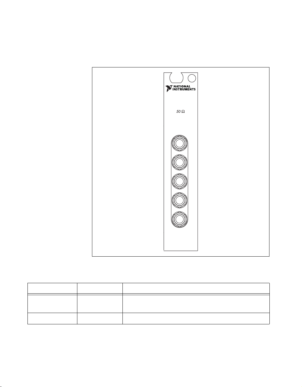
Connecting Signals
The front of the NI 2590 module has five “push-on” SMB connectors for
signal connections. The NI 2591 has five SMA female connectors. The
center connection, labeled COM, is connected in a through path to one of
the other four connections depending on the software instructions sent to
the switch.
NI 2590 Front Connector
The following diagram shows the NI 2590 front connector. Table 1-1
describes the connector signals.
Chapter 1 Routing Signals with Your NI 2590/2591
2590
1×4 1.3 GHz Mux
CH0
CH1
COM
CH2
CH3
Figure 1-1. NI 2590 Front Connector
© National Instruments Corporation 1-3 NI 2590/2591 User Manual
Page 12
Chapter 1 Routing Signals with Your NI 2590/2591
NI 2591 Front Connector
The following diagram shows the NI 2591 front connector. Table 1-1
describes the connector signals.
2591
1×4 4 GHz Mux
0
1
C
O
M
2
3
Figure 1-2. NI 2591 Front Connector
Table 1-1. Front Connector Signal Description
Signal Name Type Description
CH<0..3> Input/Output Channels—Where signals are connected to the switch
module
COM Input/Output Common—The common for the respective channel
NI 2590/2591 User Manual 1-4 ni.com
Page 13

Chapter 1 Routing Signals with Your NI 2590/2591
Software Choices
You have several options to choose from when programming your National
Instruments switch module. You can use the NI-SWITCH driver software
or National Instruments application software.
NI-SWITCH Driver Software
The NI-SWITCH instrument driver is an Interchangeable Virtual
Instrument (IVI)-compliant instrument driver that is bundled with the
module at no cost.
NI-SWITCH features a set of operations and attributes that exercise all
the functionality of the switching hardware, including configuration,
opening/closing, and scanning. In addition, NI-SWITCHNI-SWITCH
comes with an interactive soft front panel and online documentation.
NI-SWITCH eliminates the need to understand complex register
programming and interrupt handling in the Microsoft operating systems,
and frees you to focus on creating your test system.
National Instruments Application Software
LabVIEW and LabWindows/CVI are innovative program development
software packages for data acquisition and control applications. LabVIEW
uses graphical programming, whereas LabWindows/CVI enhances
traditional programming languages. Both packages include extensive
libraries for data acquisition, instrument control, data analysis, and
graphical data presentation. Using LabVIEW or LabWindows/CVI can
significantly reduce the development time for your data acquisition and
control application.
LabVIEW features interactive graphics, a state-of-the-art user interface,
and a powerful graphical programming language. The LabVIEW
NI-SWITCH VI Library, a series of virtual instruments (VIs) for using
LabVIEW with National Instruments switch hardware, is included with
the NI-SWITCH driver.
LabWindows/CVI features interactive graphics, a state-of-the-art user
interface, and uses the ANSI standard C programming language. The
LabWindows/CVI NI-SWITCH Library, a series of functions for using
LabWindows/CVI with National Instruments switch hardware, is included
with the NI-SWITCH driver.
© National Instruments Corporation 1-5 NI 2590/2591 User Manual
Page 14

Chapter 1 Routing Signals with Your NI 2590/2591
Third-Party Software
The NI-SWITCH instrument driver also includes support files for
Microsoft Visual C++ and Microsoft Visual Basic. See the NI-SWITCH
Software Readme File for version support information.
Cabling and Accessory Requirements
National Instruments recommends the use of cables and accessories with
50 Ω characteristic impedance with the NI 2590/2591.
NI 2590/2591 User Manual 1-6 ni.com
Page 15

NI 2590/2591 Operation
This chapter contains safety instructions and a functional overview of the
NI 2590/2591 switch modules. It also explains the operation of each
functional unit making up the switch module.
Safety Instructions
2
Cautions
instrument can become impaired if the instrument becomes damaged in any way. If the
instrument is damaged, do not use it until service-trained personnel can check its safety.
If necessary, return the instrument to National Instruments for service and repair to ensure
that its safety is not compromised.
Do not operate this instrument in a manner that contradicts the information specified in this
document. Misuse of this instrument could result in a shock hazard.
Do not substitute parts or modify equipment beyond what is described in Appendix B,
Servicing Your Module. Because of the danger of introducing additional hazards, do not
install unauthorized parts or modify the instrument. Return the instrument to National
Instruments for service and repair to ensure that its safety is not compromised.
Connections that exceed any of the maximum signal ratings on the NI 2590/2591 can
create a shock or fire hazard or can damage any or all of the devices connected to the
NI 2590/2591. National Instruments is not liable for any damages or injuries resulting
from incorrect signal connections.
Clean instrument and accessories by brushing off light dust with a soft, nonmetallic brush.
Remove other contaminants with a stiff nonmetallic brush. The unit must be completely
dry and free from contaminants before returning to service.
Do not operate damaged equipment. The safety protection features built into this
© National Instruments Corporation 2-1 NI 2590/2591 User Manual
Page 16

Chapter 2 NI 2590/2591 Operation
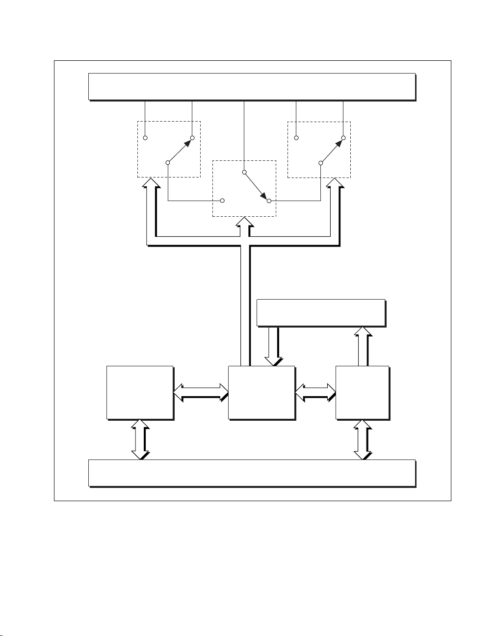
Functional Overview
The following block diagrams illustrate the key functional components of
the NI 2590 and NI 2591 switch modules.
The major components of the NI 2590/2591 are as follows:
• General-purpose high-frequency relays
• Switch control circuitry
• Random scanning
• PXIbus interface
• Triggers
NI 2590/2591 User Manual 2-2 ni.com
Page 17
CH3
CH2
Front Panel
COM
CH1
Chapter 2 NI 2590/2591 Operation
CH0
MUX23
Triggers
MUX0123
Relay Control
MUX01
Scan Memory
PXI
Interface
PXIbus Connector
Figure 2-1. NI 2590 Module Block Diagram
© National Instruments Corporation 2-3 NI 2590/2591 User Manual
Page 18

Chapter 2 NI 2590/2591 Operation
CH3
CH2
Front Panel
COM
DECODER
CH1
Control
Lines
Scan Memory
CH0
High–
Frequency
Relay
4 GHz
Relay Module
Triggers
Relay Control
PXI Bus Connector
PXI
Interface
Figure 2-2. NI 2591 Module Block Diagram
NI 2590/2591 User Manual 2-4 ni.com
Page 19

Relay Operation
NI 2590 Operation
The NI 2590 has four channels, CH0 through CH3, any one of which can
be connected to the single common channel (COM) by closing the
appropriate relays.
You can control the relays individually, or you can use higher-level
commands to energize the correct relays to connect a channel (such as
CH0) to COM. Only one channel can be connected to the common channel
at any time, and it is not possible to connect one channel to another channel
bypassing the common channel.
The NI 2590 relays are single-side stable. When power is removed from the
relay coil, the relay returns to its de-energized state. When all three relays
are de-energized, the default connection is from CH0 to COM, as shown in
Figure 2-1. To connect CH2 to COM, you energize MUX0123; to connect
CH3 to COM, you energize MUX0123 and MUX23. You can specify the
channel to connect to COM and let the NI-Switch driver energize the
appropriate relays for you. Refer to the NI-SWITCH Software User Manual
for further information.
Chapter 2 NI 2590/2591 Operation
NI 2591 Operation
The NI 2591 is very similar to the NI 2590 in some respects, but different
in others. The NI 2591 has 4 channels, CH0 through CH3, any one of which
can be connected to the single COM by closing the appropriate relays.
The NI 2591 does not allow for control of the individual relays. You must
use the high-level commands to connect the channels, such as CH2 to
COM. Only one channel can be connected to the common channel at any
time, and it is not possible to connect one channel to another channel,
bypassing the common channel. The default (power off) connection of the
NI 2591 is CH3 to COM. Refer to Figure 2-2 to see how the connections in
the NI 2591 are made.
© National Instruments Corporation 2-5 NI 2590/2591 User Manual
Page 20

Chapter 2 NI 2590/2591 Operation
Switch Control Circuitry
The switch control circuitry (SCC) is responsible for opening and closing
relays on the NI 2590/2591. You can load commands for the SCC into scan
memory using the driver software you received with your kit. Consult the
online help or your software documentation for specific information on the
appropriate commands. There are two reasons for storing the commands in
memory before the SCC can process them:
• Both the operate and release times for the NI 2590/2591 are 15 ms.
Using memory storage, the software can send multiple commands to
the SCC without having to wait for a relay action to complete.
• The memory is used to store a scan list necessary for hardware
random scanning.
Random Scanning
The NI 2590/2591 can perform random scanning. In random scanning,
the switch module can open or close relays in any order.
The scan list is downloaded to onboard memory. Commands in the scan
list can perform the following actions:
• Open or close relays
• Wait for an external trigger
• Generate a scanner advanced trigger
• Generate a breakpoint interrupt
You can use the driver software to configure the switch module for
continuous or one-time scanning. In continuous scanning, the switch
module cycles through the scan list until you disable scanning. For
one-time scanning, the switch module runs through the scan list only once.
You can also use software commands to clear the scan list or reset it to the
beginning at any time.
The onboard control logic for the NI 2590/2591 switch module gives you
direct access to open and close the relays, and also the ability to download
up to 1,024 random scanning instructions. The software included with the
module automatically configures the NI 2590/2591 and downloads the scan
list to hardware for you. The scan list itself downloads directly into the
memory of the module to deliver the fastest scan possible with no controller
NI 2590/2591 User Manual 2-6 ni.com
Page 21

PXI Interface
PXI Triggers
Chapter 2 NI 2590/2591 Operation
intervention. You can configure the switch module to process the scan list
once or to continuously loop through the scan list.
You can configure and control your NI 2590/2591 switch module through
the PXI interface, taking advantage of PXI features. The NI 2590/2591
uses the PXI TTL triggers to synchronize scanning with a measurement
device such as the NI 5102 (PXI) 20 MS/s oscilloscope, or the NI 5411
for PXI arbitrary waveform generator.
External Trigger Input
The NI 2590/2591 can use an external trigger input to advance between
scan setups in a scan list. Using the driver software, you can configure the
switch module to route the external trigger from any of the PXI TTL trigger
lines or the PXI star trigger. Alternatively, you can use a software
command to trigger the switch module.
All external trigger lines are compatible with TTL voltage levels and are
edge sensitive. The minimum pulse width from the PXI TTL triggers and
PXI star trigger is 70 ns.
Scanner Advanced
The NI 2590/2591 can generate a scanner advanced trigger to indicate
when the switch module is set up and ready to take measurements. Using
the driver software, you can configure the switch module to route the
scanner advanced (SCANADV) trigger to any PXI TTL trigger line or to
the PXI star trigger. You can configure the switch module to generate the
SCANADV trigger when a relay has settled (or debounced).
Because the NI 2590/2591 has open-collector drivers on the PXI TTL
trigger lines, you can have multiple switch modules using the same trigger
line in the multiboard SCANADV mode.
© National Instruments Corporation 2-7 NI 2590/2591 User Manual
Page 22

Chapter 2 NI 2590/2591 Operation
Modes
SCANADV has two modes of operation. In its default mode, the
SCANADV trigger asserts for 1 µs after the relay has debounced. You
can also configure the switch module for handshaking mode, in which the
SCANADV trigger goes high after a relay settles, and the SCANADV
trigger goes low after the external trigger input asserts. You can use this
handshaking mode for multiboard scanning.
Note
The NI 2590/2591 ignores external triggers when it is not in a wait-for-trigger state
while scanning.
Initiating Scanning
When you use the NI 2590/2591 to initiate a scan, make sure the
measurement device is armed (waiting for trigger) before enabling
scanning on the switch module. Enabling scanning causes the first
switch(es) in the scan list to close and generates a scanner advanced
trigger after the relay switches have settled or debounced.
When you use the measurement device to initiate a scan, make sure
scanning is enabled on the NI 2590/2591 before the measurement device
starts to take measurements. This ensures that the switch module has the
correct signal routed and that the switch module is waiting for an external
trigger from the measurement device.
Always configure the triggers in a system before configuring the
measurement device or the NI 2590/2591 for scanning. When triggers
are configured, a state change or pulse could occur on the trigger line.
This is also possible when you reset the switch module.
Multiboard Triggering
You can use multiple NI 2590/2591 switch modules—or multiple other
National Instruments switch modules such as the NI 2503—together in
conjunction with an instrument such as a National Instruments
oscilloscope/digitizer. In multiple switch-module systems, be sure to
identify one switch module as the master switch module.
All other switch modules for the system are identified as slave switch
modules. The master switch module can route an external trigger from the
front connector to a PXI backplane trigger. In addition, the master switch
module can route the SCANADV trigger from the PXI backplane to either
the front connector or another backplane trigger. This functionality makes
NI 2590/2591 User Manual 2-8 ni.com
Page 23

Chapter 2 NI 2590/2591 Operation
it possible to wire external triggers from/to only one switch module in the
system, which simplifies the wiring scheme.
Note
The NI 2590/2591 does not support triggers on the front panel connector. If the
trigger signal is external to the chassis, you must use a different National Instruments
switch module, such as the NI 2503, as the master switch module.
For more information, refer to the NI-SWITCH Software User Manual.
© National Instruments Corporation 2-9 NI 2590/2591 User Manual
Page 24

Specifications
This appendix lists the specifications for the NI 2590/2591 switch module.
These specifications are typical at 25 °C unless otherwise noted.
NI 2590
Input Characteristics
Number of relays.................................... 3
Common-mode voltage
Channel to earth ..............................24 VDC
Maximum switching voltage
AC................................................... 24 V
DC................................................... 24 VDC
Maximum switching capacity per channel
DC................................................... 1 A at 24 V
AC................................................... 1 A
rms
rms
A
at 24 V
Maximum switching
power per channel .................................. 24 W
Contact on resistance (initial) ................ 100 mΩ max
Contact material ..................................... Gold-clad silver
RF Performance Characteristics
Characteristic impedance (Z0)................ 50 Ω
Insertion loss at:
< 100 MHz ......................................< 0.4 dB
< 500 MHz ......................................< 0.9 dB
< 1.3 GHz........................................< 1.5 dB
© National Instruments Corporation A-1 NI 2590/2591 User Manual
Page 25

Appendix A Specifications for NI 2590
VSWR at:
< 100 MHz.......................................< 1.15
< 500 MHz.......................................< 1.35
< 1.3 GHz ........................................< 1.5
Isolation:
< 500 MHz.......................................< –62 dB
< 1.3 GHz ........................................< –50 dB
Risetime ..................................................< 300 ps
Signal delay ............................................< 3 ns
Maximum RF carry power
at 900 MHz .............................................10 W
Note
Refer to the cautions and warning in the RF Switching Precautions and Contact
Protection sections of Chapter 1, Routing Signals with Your NI 2590/2591, for important
information about using your NI 2590/2591 with high-power signals.
Dynamic Characteristics
Relay operate time (at 20 °C)
Typical.............................................15 ms
Relay release time (at 20 °C)
Typical.............................................15 ms
Expected life
Mechanical (no load).......................5 × 10
6
operations
Electrical at maximum
5
operations
Caution
switching capacity ...........................10
Exceeding the maximum switching capability will decrease the expected life
of the NI 2590/2591.
PXI Bus Interface
Slave
NI 2590/2591 User Manual A-2 ni.com
Page 26

PXI Trigger Bus
Power Requirement
Physical
Environment
Appendix A Specifications for NI 2590
Trigger lines ...........................................8
Star trigger.............................................. 1
+5 VDC
Minimum (all relays opened).......... 350 mA
Maximum (all relays closed) .......... 0.6 A
Dimensions............................................. 10 by 16 by 4 cm
(3.9by6.3by1.6in.)
Weight.................................................... 240 g (8.5 oz)
I/O connector.......................................... 5 SMB female
Operating temperature..........................0 to 50 °C
Storage temperature..............................–20 to 70 °C
Relative humidity................................... 5 to 85% noncondensing
Maximum altitude .................................. 2,000 m
Certifications and Compliances
CE Mark Compliance
See the Declaration of Conformity sheet accompanying product.
© National Instruments Corporation A-3 NI 2590/2591 User Manual
Page 27

Appendix A Specifications for NI 2591
NI 2591
Input Characteristics
Number of relays ....................................3
Common-mode voltage
Maximum switching voltage
Maximum switching capacity per channel
Maximum switching
power per channel...................................10 W
Contact on resistance (initial) .................200 mΩ max
Channel to earth...............................30 V
AC....................................................30 V
DC....................................................30 VDC
DC....................................................30 VDC at 0.33 ADC
AC....................................................30 V
or DC
rms
rms
at 0.33 A
rms
rms
Contact material......................................Gold
RF Performance Characteristics
Characteristic impedance (Z0) ................50 Ω
Insertion loss at:
< 2.5 GHz ........................................< 0.6 dB
< 4 GHz ...........................................< 0.9 dB
VSWR at:
< 2.5 GHz ........................................< 1.3
< 4 GHz ...........................................< 1.5
Isolation:
< 2.5 GHz ........................................< –60 dB
< 4 GHz ...........................................< –55 dB
Maximum RF carry power
at 900 MHz .............................................10 W
NI 2590/2591 User Manual A-4 ni.com
Page 28

Note
Refer to the safety information in Chapter 2, NI 2590/2591 Operation, for important
information about using your NI 2591 with high-power signals.
Dynamic Characteristics
Relay operate time (at 20 °C)
Typical ............................................ 15 ms
Relay release time (at 20 °C)
Typical ............................................ 15 ms
Expected life
Mechanical (no load) ...................... 5 × 10
Electrical at maximum
switching capacity........................... 10
Appendix A Specifications for NI 2591
6
operations
5
operations
Caution
the NI 2591.
Exceeding the maximum switching capability will decrease the expected life of
Power Requirement
Physical
Environment
+5 VDC
Maximum (all relays closed) .......... 250 mW
Weight.................................................... 1.1 kg
Dimensions............................................. 10 by 16 by 4 cm
(3.9by6.3by1.6in.)
I/O connector.......................................... 5 SMA female per bank
Operating temperature..........................0 to 50 °C
Storage temperature..............................–20 to 70 °C
Relative humidity................................... 5 to 85% noncondensing
© National Instruments Corporation A-5 NI 2590/2591 User Manual
Page 29

Appendix A Specifications for NI 2591
Electromagnetic compatibility
(EMC) emissions.............................Refer to the document supplied
EMI..................................................FCC Class A compliant
Maximum altitude...................................2,000 m
Certifications and Compliances
CE Mark Compliance
See the Declaration of Conformity sheet accompanying product.
with the chassis for compliance
to relevant directives.
NI 2590/2591 User Manual A-6 ni.com
Page 30

Servicing Your Module
This appendix describes procedures for servicing your NI 2590/2591
module.
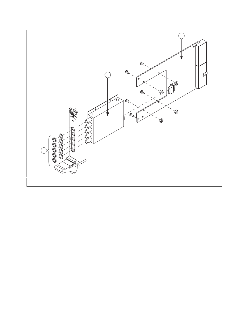
Replacing the NI 2590 Relay Module
B
The NI 2590 is constructed so that the relay module can be replaced when
the relays fail. The life of the relay is nominally 10
switching the maximum rated load.
You can order an RF 2590 replacement relay module for your NI 2590 from
National Instruments. The replacement kit contains the fully assembled
module.
1
5
4
5
operations when
2
3
1 Header
2 Relay Module
© National Instruments Corporation B-1 NI 2590/2591 User Manual
3Screws
4 SMB Connectors
Figure B-1. NI 2590 Parts Locator Diagram
5 Hex Nuts and Washers
Page 31

Appendix B Servicing Your Module
Follow these instructions to replace the failed module as shown in
Figure B-1.
1. Ground yourself with a grounding strap or a ground connected to
your PXI chassis. Properly grounding yourself prevents damage to
your PXI module from electrostatic discharge.
2. Remove the two Phillips-head screws that fasten the NI 2590 relay
module board to the module carrier.
3. Remove the hex nuts and washers from the SMB connectors on the
front panel.
4. Gently disconnect the rear of the module from the header, then
carefully remove the module.
5. Install the replacement module and screws in reverse order, taking care
not to damage the connector pins on the module.
Replacing the NI 2591 Relay Module
The NI 2591 is constructed so that the relay module can be replaced when
the relays fail. The life of the relay is nominally 10
switching the maximum rated load.
You can order an RF 2591 replacement relay module for your NI 2591 from
National Instruments. The replacement kit contains the fully assembled
module.
5
operations when
NI 2590/2591 User Manual B-2 ni.com
Page 32
Appendix B Servicing Your Module
3
2
1
1 Hex Nuts and Washers 2 Relay Module 3 Base Card
Figure B-2.
RF 2591 Replacement Relay Module
Follow these instructions to replace the failed module as shown in
Figure B-2.
1. Ground yourself with a grounding strap or a ground connected to your
PXI chassis. Properly grounding yourself prevents damage to your PXI
module from electrostatic discharge.
2. Remove the four Phillips-head screws and nuts that fasten the NI 2591
relay module to the module carrier.
3. Remove the hex nuts and washers from the SMA connectors on the
front panel.
4. Remove the PXI ejector handle screw that secures the front panel.
5. Remove the module from the base card.
6. Install the replacement module and screws in reverse order, taking care
not to damage the connector pins on the module.
© National Instruments Corporation B-3 NI 2590/2591 User Manual
Page 33

Common Questions
This appendix addresses common questions you may have while using
your NI 2590/2591 switch module.
What should I do if the software detects the module but the switches do
not switch?
Verify that the switches do not switch. Close your application program
and then launch the soft front panel as described in the Set up and Test
document you received with your kit. The soft front panel shows the state
of each relay on the module. Try closing and opening the switches.
Also be sure to check the return codes of the NI-Switch operation to ensure
that there are no errors (negative value) or warnings (positive value). You
can also use the NI-Spy utility to check for error codes.
Finally, verify that your code is correct. For reference, see the examples
described in the NI-SWITCH Software User Manual. The NI-Switch driver
also ships with several examples in source code. Compare your algorithm
to those in the examples.
C
What should I do if scanning does not work?
First, ensure that you have configured the switch module and the instrument
to match trigger lines. The output trigger of the instrument should connect
to the trigger input of the switch module. In addition, the scanner advanced
trigger of the switch module should be connected to the input trigger of the
instrument.
If the switch module is used to initiate the scan, make sure the scope or arb
is waiting for a trigger before enabling scanning on the switch module. This
is the recommended method for hardware scanning.
If the scope or arb is used to initiate the scan, enable scanning on the switch
module before configuring the scope or arb to start taking measurements.
Also be sure to check the return codes of the NI-Switch operation to ensure
that there are no errors (negative value) or warnings (positive value). You
can also use the NI-Spy utility to check for error codes.
© National Instruments Corporation C-1 NI 2590/2591 User Manual
Page 34

Appendix C Common Questions
Finally, verify that your code is correct. For reference, see the examples
described in the NI-SWITCH Software User Manual. The NI-Switch driver
also ships with several examples in source code. Compare your algorithm
to the ones in the examples.
Do I need to program the switch module myself?
The NI 2590/2591 comes with the NI-Switch driver software, which
exports the full functionality of the module. NI-Switch handles the
complex issues of direct memory access, interrupts, and operating
system interfacing.
NI 2590/2591 User Manual C-2 ni.com
Page 35

Technical Support Resources
Web Support
National Instruments Web support is your first stop for help in solving
installation, configuration, and application problems and questions. Online
problem-solving and diagnostic resources include frequently asked
questions, knowledge bases, product-specific troubleshooting wizards,
manuals, drivers, software updates, and more. Web support is available
through the Technical Support section of
NI Developer Zone
ni.com
D
The NI Developer Zone at
building measurement and automation systems. At the NI Developer Zone,
you can easily access the latest example programs, system configurators,
tutorials, technical news, as well as a community of developers ready to
share their own techniques.
Customer Education
National Instruments provides a number of alternatives to satisfy your
training needs, from self-paced tutorials, videos, and interactive CDs to
instructor-led hands-on courses at locations around the world. Visit the
Customer Education section of
syllabi, training centers, and class registration.
System Integration
If you have time constraints, limited in-house technical resources, or other
dilemmas, you may prefer to employ consulting or system integration
services. You can rely on the expertise available through our worldwide
network of Alliance Program members. To find out more about our
Alliance system integration solutions, visit the System Integration section
of
ni.com
ni.com/zone
ni.com
is the essential resource for
for online course schedules,
© National Instruments Corporation D-1 NI 2590/2591 User Manual
Page 36

Appendix D Technical Support Resources
Worldwide Support
National Instruments has offices located around the world to help address
your support needs. You can access our branch office Web sites from the
Worldwide Offices section of
up-to-date contact information, support phone numbers, e-mail addresses,
and current events.
If you have searched the technical support resources on our Web site and
still cannot find the answers you need, contact your local office or National
Instruments corporate. Phone numbers for our worldwide offices are listed
at the front of this manual.
ni.com
. Branch office Web sites provide
NI 2590/2591 User Manual D-2 ni.com
Page 37

Glossary
Prefix Meaning Value
p- pico- 10
n- nano- 10
µ- micro- 10
m- milli- 10
M- mega- 10
G- giga- 10
Numbers and Symbols
° degrees
Ω ohms
% percent
–12
–9
– 6
–3
6
9
> greater than
< less than
A
A amperes
AC alternating current
ADC amperes direct current
ANSI American National Standards Institute
© National Instruments Corporation G-1 NI 2590/2591 User Manual
Page 38

Glossary
B
breakpoint a specified point in program code where the program pauses to perform
some action; a breakpoint interrupt can be added to a scan list for
debugging or other special needs.
bus the group of conductors that interconnect individual circuitry in a computer.
Typically, a bus is the expansion vehicle to which I/O or other devices are
connected. Examples of PC buses are the ISA and PCI bus.
C
CCelsius
channel pin or wire lead on the multiplexer to which you apply or from which you
read the signal
common a channel that is typically the output of a switch module
contact bounce the intermittent switching that occurs when the movable metal parts of a
relay make or break contact
D
DC direct current
debounced indicates when the contact bounce has ended. See contact bounce.
device a plug-in module, board, or pad that can contain multiple channels and
conversion devices. Some examples of devices are computers,
multimeters, multiplexers, oscillators, operator interfaces, and
counters.
diode an electronic component that acts primarily as a one-way valve
drivers/driver software software that controls a specific hardware device such as a switch module
E
external trigger a voltage pulse from an external source that triggers an event such as
A/D conversion
NI 2590/2591 User Manual G-2 ni.com
Page 39

Glossary
F
flyback voltage the voltage spike generated the instant current stops flowing through an
inductor
H
handshaking the use of two trigger lines between two instruments, such as a switch and
a DMM, to synchronize their actions
Hz hertz—the number of scans read or updates written per second
I
in. inches
Interchangeable
Virtual Instrument
I/O input/output—the transfer of data to/from a computer system involving
ISA Industry Standard Architecture
IVI See Interchangeable Virtual Instrument.
an advanced architecture for instrument drivers that includes features such
as simulation and state caching
communications channels, operator interface devices, and/or data
acquisition and control interfaces
N
NI-Switch an IVI-based instrument driver that supports the National Instruments line
of switch modules
P
PXI PCI with extensions for instrumentation
© National Instruments Corporation G-3 NI 2590/2591 User Manual
Page 40

Glossary
R
random scanning scanning the channels in a mux in any order
reflective switch a switch architecture in which the unused channels are NOT terminated in
the characteristic impedance of the system. The unused channels are open
circuits.
relay a switch that connects or disconnects the signal to a common through the
physical movement of a metal arm
rms root mean square—the square root of the average value of the square of the
instantaneous signal amplitude; a measure of signal amplitude
S
s seconds
scan the data acquisition of signals connected to multiple channels of a
multiplexer. Typically, the measurement device uses a trigger to advance
the multiplexer to the next channel in the scan.
scan list a list of channels supplied to NI-Switch that indicates the order in which
channels will be scanned
scanner advanced
trigger
SCC switch control circuitry
SMB sub-miniature snap-on connector
soft front panel a graphical program included with NI-Switch that you can use to
the trigger generated by the switch module when scanning. The trigger
occurs after the switch module has closed a switch and the switch has
settled.
interactively control the switch
T
trigger any event that causes or starts some form of data capture
TTL Transistor-Transistor Logic
NI 2590/2591 User Manual G-4 ni.com
Page 41

Glossary
V
V volts
varistor an electrical resistor whose resistance depends on the applied voltage
VDC volts, direct current
VI virtual instrument—(1) a combination of hardware and/or software
elements, typically used with a PC, that has the functionality of a classic
stand-alone instrument (2) a LabVIEW software module (VI), which
consists of a front panel user interface and a block diagram program
VSWR Voltage Standing Wave Ratio. The impedance match of the device to the
overall system.
W
Wwatts
wire data path between nodes
© National Instruments Corporation G-5 NI 2590/2591 User Manual
Page 42

Index
B
block diagrams
NI 2590, 2-3
NI 2591, 2-4
C
cables and accessories, 1-6
certification and compliances
NI 2590, A-3
NI 2591, A-6
CH<0..3> signal (table), 1-4
COM signal (table), 1-4
common questions about NI 2590/2591,
C-1toC-2
connectors
front connector
NI 2590 (figure), 1-3
NI 2591 (figure), 1-4
overview, 1-3
signal descriptions for front connectors
(table), 1-4
contact protection, 1-2
conventions used in manual, vi
customer education, D-1
D
debouncing of switches, 1-1
dynamic characteristics
NI 2590, A-2
NI 2591, A-5
E
environment specifications
NI 2590, A-3
NI 2591, A-5 to A-6
external trigger input, 1-2, 2-7
F
front connector
NI 2590 front connector (figure), 1-3
NI 2591 front connector (figure), 1-4
signal descriptions (table), 1-4
I
input characteristics
NI 2590, A-1
NI 2591, A-4
L
LabVIEW and LabWindows/CVI software, 1-5
M
maintaining the NI 2590. See servicing the
NI 2590/2591.
multiboard triggering, 2-8 to 2-9
N
National Instruments application software, 1-5
NI 2590/2591 switch module. See also operation
of NI 2590/2591.
block diagrams, 2-3 to 2-4
cabling and accessories, 1-6
common questions, C-1 to C-2
connecting signals, 1-3
© National Instruments Corporation I-1 NI 2590/2591 User Manual
Page 43

Index
contact protection, 1-2
front connectors (figures), 1-3 to 1-4
overview, 1-1
parts locator diagram
NI 2590, B-1
NI 2591, B-3
replacing relay module
NI 2590, B-1 to B-2
NI 2591, B-2 to B-3
RF switching precautions, 1-2
servicing,B-1toB-3
software choices, 1-5 to 1-6
triggers, 1-1 to 1-2
NI Developer Zone, D-1
NI-Switch instrument driver, 1-5, C-2
O
operation of NI 2590/2591, 2-1 to 2-9
block diagrams
NI 2590, 2-3
NI 2591, 2-4
functional overview, 2-2
PXI interface, 2-7 to 2-9
initiating scanning, 2-8
multiboard triggering, 2-8 to 2-9
PXI triggers, 2-7 to 2-8
random scanning, 2-6 to 2-7
relay operation
NI 2590, 2-5
NI 2591, 2-5
safety instructions, 2-1
switch control circuitry, 2-6
P
parts locator diagram
NI 2590, B-1
NI 2591, B-3
physical specifications
NI 2590, A-3
NI 2591, A-5
power requirement specifications
NI 2590, A-3
NI 2591, A-5
programming. See NI-Switch instrument
driver; software choices.
PXI interface, 2-7 to 2-9
bus interface specifications, A-2
initiating scanning, 2-8
multiboard triggering, 2-8 to 2-9
PXI triggers, 2-7 to 2-8
external trigger input, 1-2, 2-7
modes of operation, 2-8
overview, 1-1
scanner advanced, 1-1, 2-7
trigger bus specifications, A-3
Q
questions about NI 2590/2591, C-1 to C-2
R
random scanning, 2-6 to 2-7
reflective switch, 1-2
relay module, replacing
NI 2590, B-1 to B-2
NI 2591, B-2 to B-3
relay operation
NI 2590, 2-5
NI 2591, 2-5
RF performance characteristics
NI 2590, A-1 to A-2
NI 2591, A-4 to A-5
RF switching precautions, 1-2
NI 2590/2591 User Manual I-2 ni.com
Page 44

Index
S
safety instructions, 2-1
scanner advanced trigger
modes of operation, 2-8
overview, 1-1
purpose and use, 2-7
scanning
common questions, C-1 to C-2
initiating, 2-8
random scanning, 2-6 to 2-7
servicing the NI 2590/2591, B-1 to B-3
parts locator diagram
NI 2590, B-1
NI 2591, B-3
replacing relay module
NI 2590, B-1 to B-2
NI 2591, B-2 to B-3
signal descriptions for front connector
(table), 1-4
software choices, 1-5 to 1-6
National Instruments application
software, 1-5
NI-Switch instrument driver, 1-5
third-party software, 1-6
specifications, A-1 to A-6
certification and compliances
NI 2590, A-3
NI 2591, A-6
dynamic characteristics
NI 2590, A-2
NI 2591, A-5
environment
NI 2590, A-3
NI 2591, A-5 to A-6
input characteristics
NI 2590, A-1
NI 2591, A-4
physical
NI 2590, A-3
NI 2591, A-5
power requirement
NI 2590, A-3
NI 2591, A-5
PXI bus interface, A-2
PXI trigger bus, A-3
RF performance characteristics
NI 2590, A-1 to A-2
NI 2591, A-4 to A-5
switch control circuitry, 2-6
switches do not switch, C-1
system integration, by National
Instruments, D-1
T
technical support resources, D-1 to D-2
third-party software, 1-6
triggering, multiboard, 2-8 to 2-9
triggers. See PXI triggers.
W
Web support from National Instruments, D-1
Worldwide technical support, D-2
© National Instruments Corporation I-3 NI 2590/2591 User Manual
 Loading...