

National Instruments myRIO-1950 User Manual
USER GUIDE AND SPECIFICATIONS
NI myRIO-1950
The National Instruments myRIO-1950 is an embedded reconfigurable I/O (RIO) device that
students can use to design control, robotics, and mechatronics systems. This document contains
pinouts, connectivity information, dimensions, mounting instructions, and specifications for the
NI myRIO-1950.
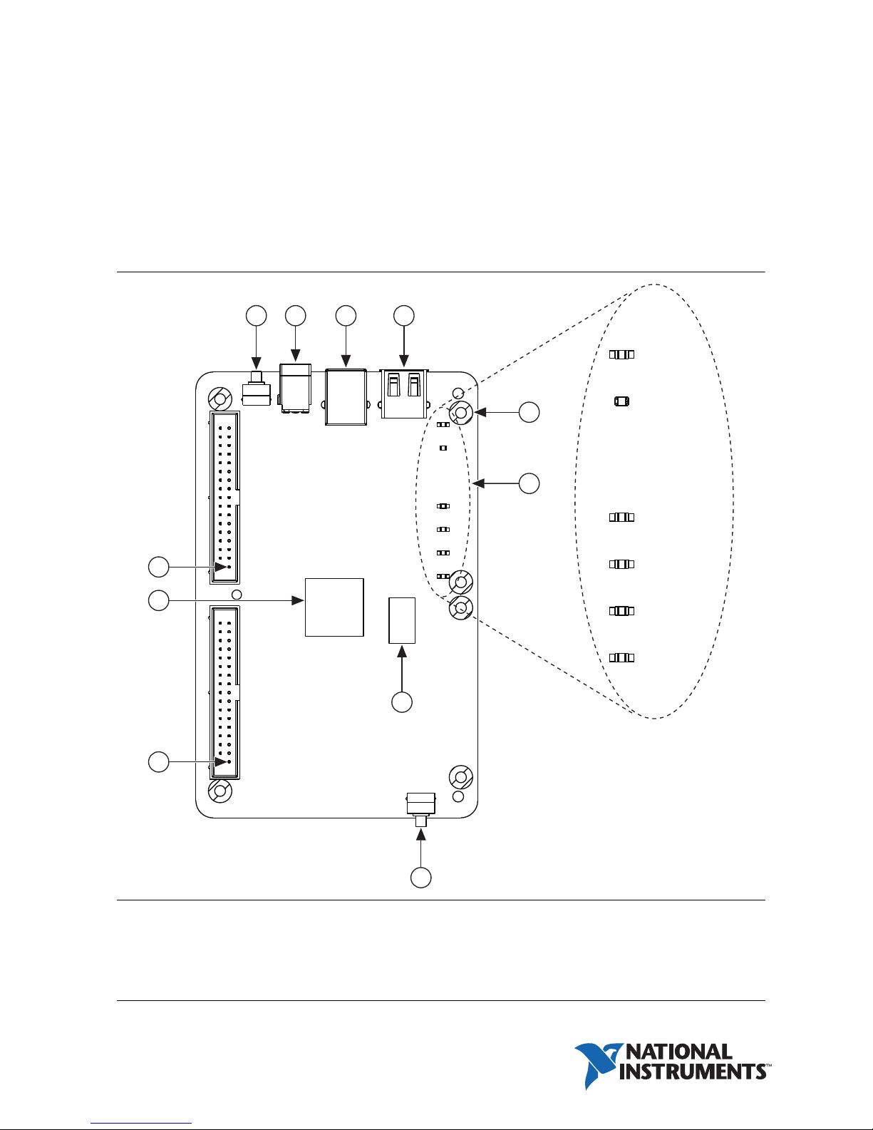
Figure 1. NI myRIO-1950
1
2 3 4
POWER
11
10
5
6
7
9
STATUS
LED 0
LED 1
LED 2
LED 3
1 Reset Button
2 Power Connector
3 Device USB Connector
4 Host USB Connector
5 Mounting Hole Connected to Chassis Ground (x6)
6LEDs
8
7 DDR3 Memory
8User Button
9 MXP Connector B, Pin 1
10 Processor/FPGA
11 MXP Connector A, Pin 1
Safety Information
Caution Do not operate the hardware in a manner not specified in this document
and in the user documentation. Misuse of the hardware can result in a hazard. You
can compromise the safety protection if the hardware is damaged in any way. If the
hardware is damaged, return it to National Instruments for repair.
Clean the hardware with a soft, nonmetallic brush. Make sure that the hardware is completely
dry and free from contaminants before returning it to service.
Electromagnetic Compatibility Guidelines
This product was tested and complies with the regulatory requirements and limits for
electromagnetic compatibility (EMC) stated in the product specifications. These requirements
and limits provide reasonable protection against harmful interference when the product is
operated in the intended operational electromagnetic environment.
This product is intended for use in commercial locations. There is no guarantee that harmful
interference will not occur in a particular installation or when the product is connected to a test
object. To minimize interference with radio and television reception and prevent unacceptable
performance degradation, install and use this product in strict accordance with the instructions
in the product documentation.
Furthermore, any modifications to the product not expressly approved by National Instruments
could void your authority to operate it under your local regulatory rules.
Caution To ensure the specified EMC performance, the length of any cable
connected to the USB ports must be no longer than 3 m (10 ft), and the length of any
cable connected to the MXP ports must be no longer than 0.3 m (1 ft).
Caution To ensure the specified EMC performance, do not connect the power input
to a DC mains supply or to any supply requiring a connecting cable longer than 3 m
(10 ft). A DC mains supply is a local DC electricity supply network in the
infrastructure of a site or building.
2 | ni.com | NI myRIO-1950 User Guide and Specifications
ESD Warning
Caution Although this product has been designed to be as robust as possible, ESD
(electrostatic discharge) can damage or upset this product. This product must be
protected at all times from ESD. Static charges may easily produce potentials of
several kilovolts on the human body or equipment, which can discharge without
detection. Industry-standard ESD precautions must be employed at all times.
The NI myRIO-1950 is designed and intended for use as a development platform for
hardware or software in an educational/professional laboratory environment. To
facilitate usage, the board is manufactured with its components and connecting traces
openly exposed to the operator and the environment. As a result, ESD sensitive
(ESDS) components on the board, such as the semiconductor integrated circuits, can
be damaged when exposed to an ESD event. To indicate the ESD sensitivity of the
NI myRIO-1950, it carries the symbol shown below.
NI myRIO-1950 User Guide and Specifications | © National Instruments | 3
Hardware Overview
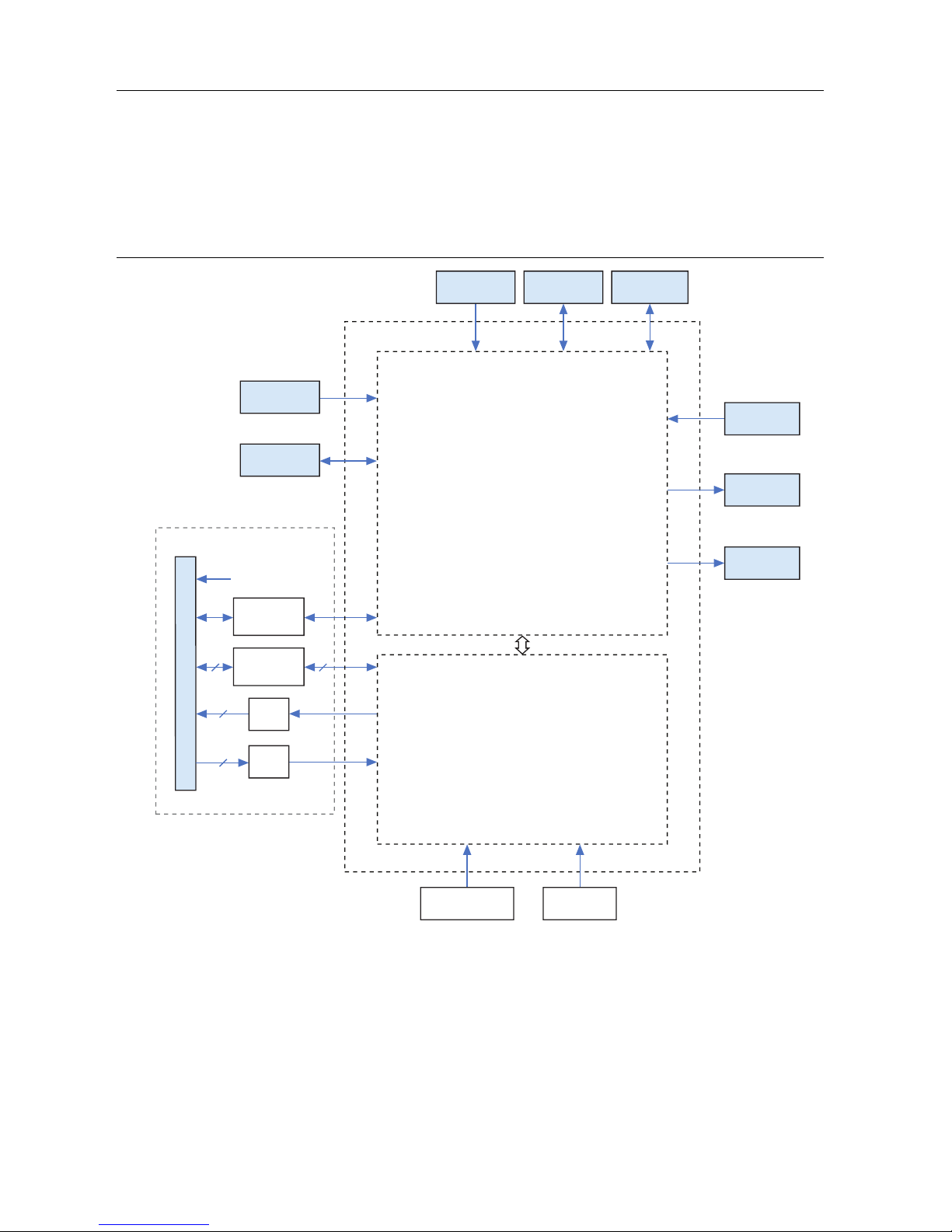
The NI myRIO-1950 provides analog input (AI), analog output (AO), digital input and output
(DIO), and power output in a compact embedded device. The NI myRIO-1950 connects to a host
computer over USB.
The following figure shows the arrangement and functions of NI myRIO-1950 components.
Figure 2. NI myRIO-1950 Hardware Block Diagram
(x2)
MXP A/B
Nonvolatile
Memory
DDR3
+3.3 V
UART
16 16
DIO
2
AO
Xilinx Zynq-7010
Processor (LabVIEW RT)
Reset
Button
USB Device
Port
USB Host
Port
Watchdog
Status
LED
User
LEDs
4
AI
FPGA (LabVIEW FPGA)
Accelerometer Button0
4 | ni.com | NI myRIO-1950 User Guide and Specifications
Connector Pinouts
AO0
AO1
AGND
DGND
UART.RX
DGND
UART.TX
DGND
DIO11 / ENC.A
DGND
DIO12 / ENC.B
DGND
DIO13
DGND
DGND
DIO14 / I2C.SCL
DIO15 / I2C.SDA
+5V
AI1
AI3
AI2
DIO1
DIO2
DIO3
DIO4
AI0
DIO0
DIO5 / SPI.CLK
DIO6 / SPI.MISO
DIO7 / SPI.MOSI
DIO8 / PWM0
DIO9 / PWM1
DIO10 / PWM2
+3.3 V
3433323130292827262524
23
22
21
20
191817
1615141312111098
7
654
3
2
1
NI myRIO-1950 Expansion Port (MXP) connectors A and B carry identical sets of signals. The
signals are distinguished in software by the connector name, as in
ConnectorB/DIO1. Refer to the software documentation for information about configuring
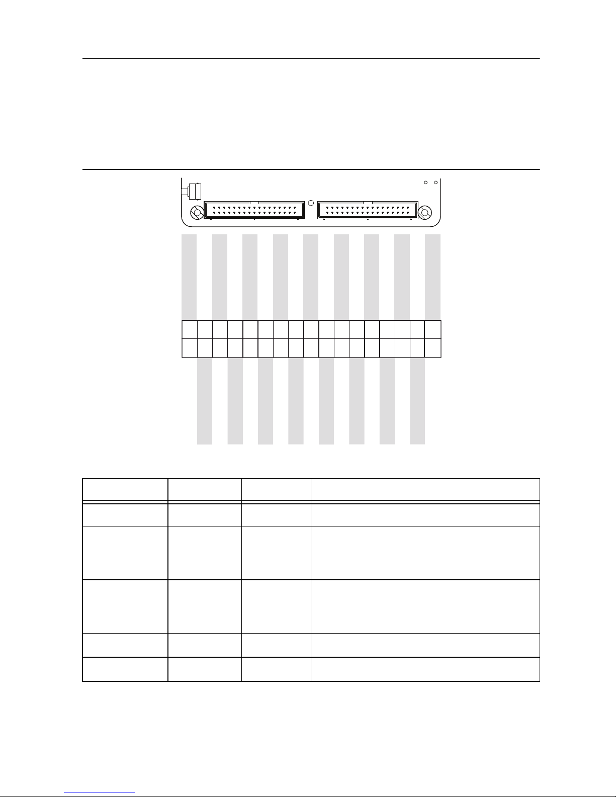
and using signals. The following figure and table show the signals on MXP connectors A and B.
Note that some pins carry secondary functions as well as primary functions.
Figure 3. Primary/Secondary Signals on MXP Connectors A and B
ConnectorA/DIO1 and
Table 1. Descriptions of Signals on MXP Connectors A and B
Signal Name Reference Direction Description
+5V DGND Output +5 V power output.
AI <0..3> AGND Input 0-5 V, referenced, single-ended analog input
channels. Refer to the Analog Input
Channels section for more information.
AO <0..1> AGND Output 0-5 V referenced, single-ended analog
output. Refer to the Analog Output Channels
section for more information.
AGND N/A N/A Reference for analog input and output.
+3.3V DGND Output +3.3 V power output.
NI myRIO-1950 User Guide and Specifications | © National Instruments | 5

Table 1. Descriptions of Signals on MXP Connectors A and B (Continued)
Signal Name Reference Direction Description
DIO <0..15> DGND Input or
Output
General-purpose digital lines with 3.3 V
output, 3.3 V/5 V-compatible input. Refer to
the DIO Lines section for more information.
UART.RX DGND Input UART receive input. UART lines are
electrically identical to DIO lines.
UART.TX DGND Output UART transmit output. UART lines are
electrically identical to DIO lines.
DGND N/A N/A Reference for digital signals, +5 V, and +3.3 V.
Analog Input Channels
The NI myRIO-1950 has analog input channels on myRIO Expansion Port (MXP) connectors A
and B. The analog inputs are multiplexed to a single analog-to-digital converter (ADC) that
samples all channels.
MXP connectors A and B have four single-ended analog input channels per connector, AI0-AI3,
which you can use to measure 0-5 V signals.
Note For important information about improving measurement accuracy by
reducing noise, go to ni.com/info and enter the Info Code analogwiring.
Figure 4 shows the analog input topology of the NI myRIO-1950.
Figure 4. NI myRIO-1950 Analog Input Topology
AI0
MXP A
0–5 V
MXP B
AI1
AI2
AI3
MUX
AI0
AI1
AI2
AI3
ADC
6 | ni.com | NI myRIO-1950 User Guide and Specifications
 Loading...