

National Instruments myDAQ User Manual
USER GUIDE
1
A
MA
X
60
V
2
0
V
r
ms
MA
X
VΩ
A
NI myDAQ
DeutschFrançais
ni.com/manuals
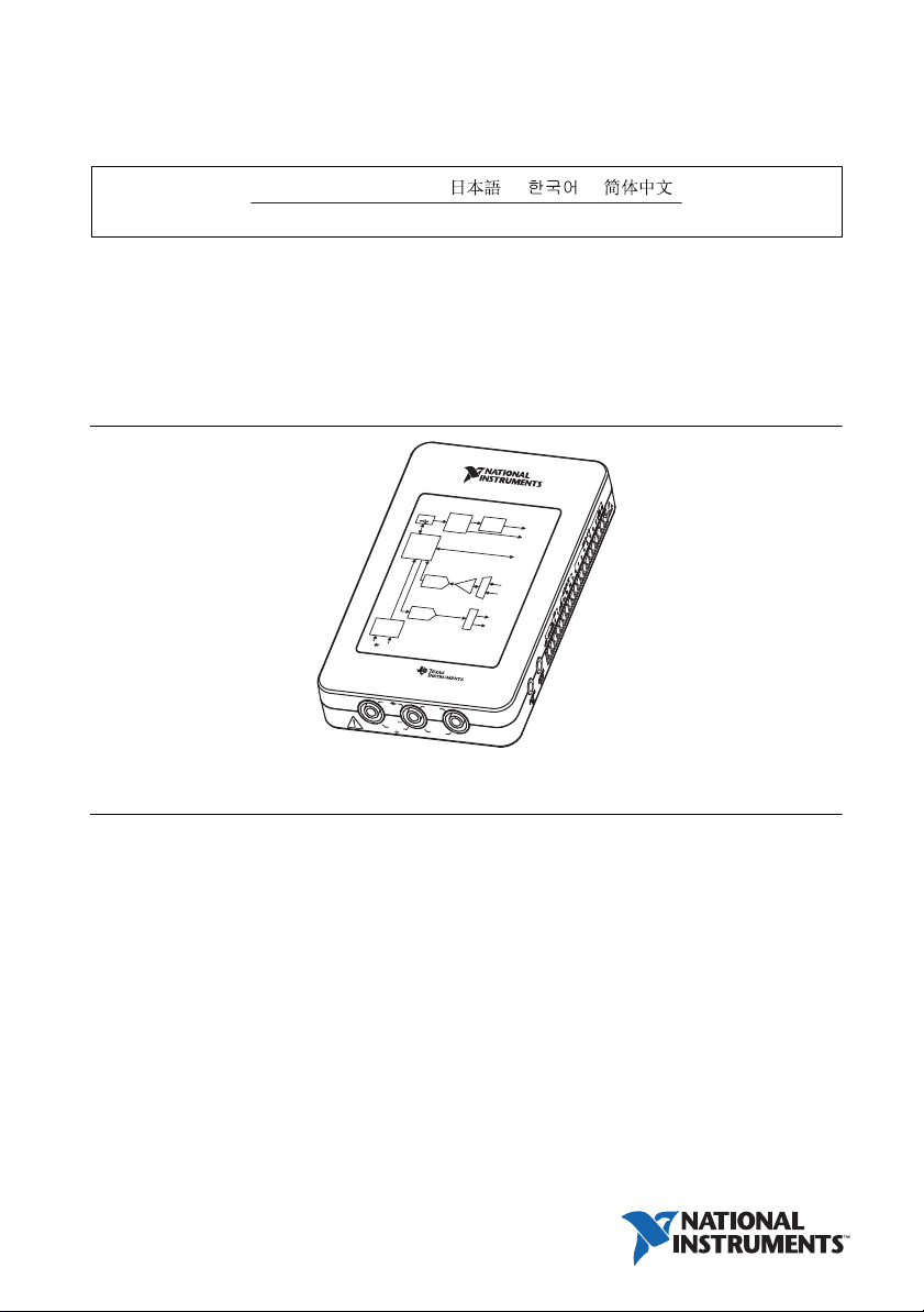
NI myDAQ is a low-cost portable data acquisition (DAQ) device that uses NI LabVIEW-based
software instruments, allowing students to measure and analyze real-world signals. NI myDAQ
is ideal for exploring electronics and taking sensor measurements. Combined with NI LabVIEW
on the PC, students can analyze and process acquired signals and control simple processes
anytime, anywhere.
Figure 1. NI myDAQ
NI myDAQ
P
ower Supply
US
B
Cu
rr
e
nt
D
C-to
DC
L
imit
e
r
Co
n
ve
r
ter
±
15 V
5
S
ystem
T
imin
g
Digital I
Con
t
roller
Analog
Analog-
to-Digital
Co
nverte
r
A
n
alog
Output
D
ig
it
a
l-
to
A
n
a
lo
g
Co
n
v
e
r
te
r
D
ig
ita
l
M
u
ltimet
e
r
V
Ω
A
NI
myDA
Q
A
n
s
u
p
p
VΩ
20 V
M
AX
H
I
S
a
l
o
g
I
C
s
li
e
d
b
y
r
ms
1
A
C
MA
O
X
M
H
V
n
put/Output
DI
O
In
put
r
e
x
e
G
a
in
AI
pl
i
t
ul
AUD
M
I
O
IN
h
c
AO
it
Sw
AU
D
I
O
O
U
T
y
st
em
D
iagr
am
I
Contents
Safety Information .................................................................................................................... 2
Electromagnetic Compatibility Guidelines .............................................................................. 3
NI myDAQ Hardware Overview.............................................................................................. 3
Analog Input (AI) .............................................................................................................4
Analog Output (AO) ......................................................................................................... 4
Digital Input/Output (DIO)............................................................................................... 5
Power Supplies ................................................................................................................. 5
Digital Multimeter (DMM) .............................................................................................. 5
NI myDAQ Software Overview ............................................................................................... 6
NI ELVISmx Driver Software.......................................................................................... 6
NI LabVIEW and NI ELVISmx Express VIs ..................................................................6
NI myDAQ and NI Multisim............................................................................................ 6
Getting Started .......................................................................................................................... 6

Making Signal Connections with NI myDAQ..........................................................................7
Setting up Your NI myDAQ Device.................................................................................7
Connecting Signals ...........................................................................................................9
Connecting Analog Input Signals ..................................................................................... 10
NI myDAQ DMM Fuse Replacement .............................................................................. 13
Digital I/O (DIO) and Counters/Timers.................................................................................... 15
Using NI myDAQ with NI ELVISmx Software Instruments ...................................................16
NI ELVISmx Instrument Launcher .................................................................................. 17
Digital Multimeter (DMM)...............................................................................................18
Oscilloscope (Scope) ........................................................................................................ 19
Function Generator (FGEN) ............................................................................................. 20
Bode Analyzer .................................................................................................................. 21
Dynamic Signal Analyzer (DSA) .....................................................................................22
Arbitrary Waveform Generator (ARB).............................................................................23
Digital Reader ................................................................................................................... 24
Digital Writer .................................................................................................................... 25
Example: Measuring a Signal Using the NI ELVISmx Oscilloscope
with NI myDAQ ............................................................................................................ 26
Using NI myDAQ with LabVIEW ...........................................................................................27
NI ELVISmx Express VIs in LabVIEW...........................................................................27
Example: Measuring Signals Using the NI ELVISmx Oscilloscope Express VI
with NI myDAQ ............................................................................................................ 28
Using NI-DAQmx with NI myDAQ ................................................................................30
Example: Measuring Audio Pass-Through in LabVIEW with NI myDAQ .....................30
Texas Instruments Components in NI myDAQ........................................................................ 34
Resource Conflicts .................................................................................................................... 35
Additional Resources ................................................................................................................ 37
Related Documentation..................................................................................................... 37
Other Resources ................................................................................................................ 38
Common Terms and Acronyms........................................................................................38
Warranty ........................................................................................................................... 39
Worldwide Support and Services ..................................................................................... 39
Safety Information
Caution Do not operate the hardware in a manner not specified in this document
and in the user documentation. Misuse of the hardware can result in a hazard. You
can compromise the safety protection if the hardware is damaged in any way. If the
hardware is damaged, return it to National Instruments for repair.
Clean the hardware with a soft, nonmetallic brush. Make sure that the hardware is completely
dry and free from contaminants before returning it to service.
2 | ni.com | NI myDAQ User Guide
Electromagnetic Compatibility Guidelines
Cautions To ensure the specified EMC performance:
• The USB cable must be less than 2.0 m (6.6 ft) in length.
• The length of any wire or cable connected to the 20-pin screw terminal
connector must be no longer than 0.3 m (1 ft).
• The length of any wire or cable connected to the Audio or DMM ports must be
no longer than 3 m (10 ft).
This product was tested and complies with the regulatory requirements and limits for
electromagnetic compatibility (EMC) as stated in the product specifications. These requirements
and limits are designed to provide reasonable protection against harmful interference when the
product is operated in its intended operational electromagnetic environment.
This product is intended for use in residential, commercial, and industrial locations. There is no
guarantee that harmful interference will not occur in a particular installation or when the product
is connected to a test object. To minimize the potential for the product to cause interference to
radio and television reception or to experience unacceptable performance degradation, install
and use this product in strict accordance with the instructions in the product documentation.
Furthermore, any changes or modifications to the product not expressly approved by National
Instruments could void your authority to operate it under your local regulatory rules.
NI myDAQ Hardware Overview
NI myDAQ provides analog input (AI), analog output (AO), digital input and output (DIO),
audio, power supplies, and digital multimeter (DMM) functions in a compact USB device.
Tip The Common Terms and Acronyms section has a list of acronyms and terms
that you will see in this manual, and in many engineering and measurement
documents and websites.
Integrated circuits supplied by Texas Instruments form the power and analog I/O subsystems of
NI myDAQ. Figure 2 depicts the arrangement and function of the NI myDAQ subsystems. Refer
to Table 5 for more information on all of the Texas Instruments components used in NI myDAQ.
NI myDAQ User Guide | © National Instruments | 3
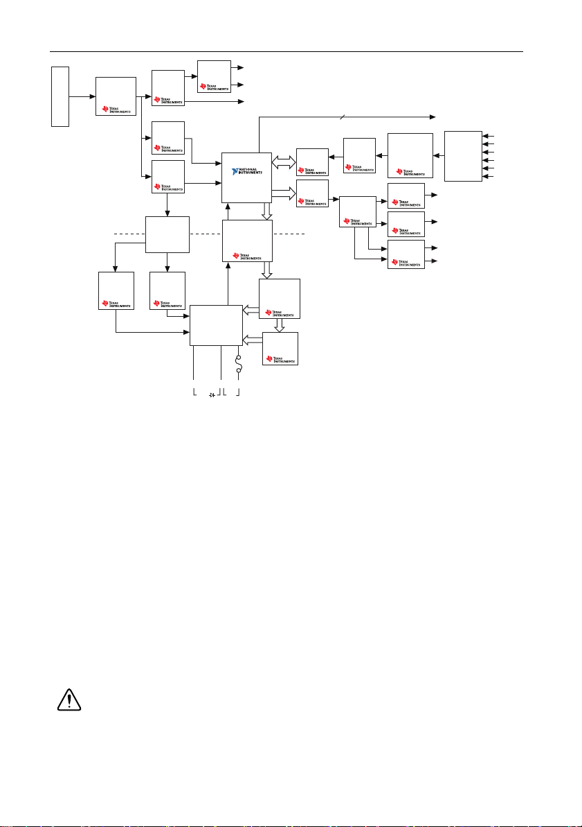
Figure 2. NI myDAQ Hardware Block Diagram
Protection
Circuit
(CSD25302Q2)
DC/DC
Isolation
Transformer
LDO
Regulator
(TPS76433)
LDO
Regulator
(TPS76433)
VBUS
Isolated +3.3 V
+15 V
+3.3 V
+1.2 V
+5 V
–15 V
USB-STC3
Digital
Isolator
(ISO7241)
DMM
Shift
Register
(SN74AHC595)
Switch
(TS5A3159)
Regulator
(TPS61170)
Isolation
Barrier
HI
HI
COM
DAC
(DAC8551)
Switch
(TS12A44514)
Gain
(TLE2082)
OP AMP
(OPA1642)
Audio AMP
(TPA6110A2)
AO 0
AO 1
Line Out R
Line Out L
Instrumentation
Amplifier
(OPA1642)
Channel
Multiplexer
AI 0–
AI 0+
AI 1–
AI 1+
Line In L
Line In R
8
DIO x
USB Connector
Regulator
(TPS62007)
Regulator
(TPS62003)
ADC
(ADS8319)
OP AMP
(OPA1642)
Current
Limiter
(TPS2553)
(V Ω ) (A)
+3.3 V
LDO
Regulator
(TPS71501)
Isolated +5 V
Note: NI myDAQ components may be changed or substituted without notice.
Analog Input (AI)
There are two analog input channels on NI myDAQ. These channels can be configured either as
general-purpose high-impedance differential voltage input or audio input. The analog inputs are
multiplexed, meaning a single analog-to-digital converter (ADC) is used to sample both
channels. In general-purpose mode, you can measure up to ±10 V signals. In audio mode, the
two channels represent left and right stereo line level inputs. Analog inputs can be measured at
up to 200 kS/s per channel, so they are useful for waveform acquisition. Analog inputs are used
in the NI ELVISmx Oscilloscope, Dynamic Signal Analyzer, and Bode Analyzer instruments.
Analog Output (AO)
There are two analog output channels on NI myDAQ. These channels can be configured as either
general-purpose voltage output or audio output. Both channels have a dedicated
digital-to-analog converter (DAC), so they can update simultaneously. In general-purpose
mode, you can generate up to ±10 V signals. In audio mode, the two channels represent left and
right stereo outputs.
Caution f using earphones to listen to the audio output of the NI myDAQ, ensure
that the volume is set to a safe level. Listening to audio signals at a high volume may
result in permanent hearing loss.
4 | ni.com | NI myDAQ User Guide

Analog outputs can be updated at up to 200 kS/s per channel, making them useful for waveform
generation. Analog outputs are used in the NI ELVISmx Function Generator, Arbitrary
Waveform Generator, and Bode Analyzer instruments.
Digital Input/Output (DIO)
There are eight DIO lines on NI myDAQ. Each line is a Programmable Function Interface (PFI),
meaning that it can be configured as a general-purpose software-timed digital input or output, or
it can act as a special function input or output for a digital counter. Refer to Digital I/O (DIO)
and Counters/Timers section for more information about the counter on NI myDAQ.
Note The digital I/O lines are 3.3 V LVTTL and are tolerant to 5 V inputs. The
digital output is not compatible with 5 V CMOS logic levels.
Power Supplies
There are three power supplies available for use on NI myDAQ. +15 V and -15 V can be used
to power analog components such as operational amplifiers and linear regulators. +5 V can be
used to power digital components such as logic devices.
The total power available for the power supplies, analog outputs, and digital outputs is limited
to 500 mW (typical)/100 mW (minimum). To calculate the total power consumption of the
power supplies, multiply the output voltage by the load current for each voltage rail and sum
them together. For digital output power consumption, multiply 3.3 V by the load current. For
analog output power consumption, multiply 15 V by the load current. Using audio output
subtracts 100 mW from the total power budget.
For example, if you use 50 mA on +5 V, 2 mA on +15 V, 1 mA on -15 V, use four DIO lines to
drive LEDs at 3 mA each, and have a 1 mA load on each AO channel, the total output power
consumption is:
5 V × 50 mA = 250 mW
|+15 V| × 2 mA = 30 mW
|-15 V| × 1 mA = 15 mW
3.3 V × 3 mA × 4 = 39.6 mW
15 V × 1 mA × 2 = 30 mW
Total output power consumption = 250 mW + 30 mW + 15 mW + 39.6 mW +
30 mW = 364.6 mW
Digital Multimeter (DMM)
The NI myDAQ DMM provides the functions for measuring voltage (DC and AC), current (DC
and AC), resistance, and diode voltage drop.
DMM measurements are software-timed, so update rates are affected by the load on the
computer and USB activity.
NI myDAQ User Guide | © National Instruments | 5

NI myDAQ Software Overview
NI ELVISmx Driver Software
NI ELVISmx is the driver software that supports NI myDAQ. NI ELVISmx uses
LabVIEW-based software instruments to control the NI myDAQ device, providing the
functionality of a suite of common laboratory instruments. Refer to the Using NI myDAQ with
NI ELVISmx Software Instruments section for information on the NI ELVISmx suite of
measurement instruments.
NI ELVISmx is located on your driver software installation media included in the NI myDAQ
kit, or can be found by searching for
drivers
of LabVIEW, go to
. To determine the version of NI ELVISmx software support required for your version
ni.com/info and enter the Info Code exsbw6.
NI LabVIEW and NI ELVISmx Express VIs
Also installed with NI ELVISmx are the LabVIEW Express VIs, which use NI ELVISmx
software instruments to program NI myDAQ with more enhanced functionality. For more
information on the NI ELVISmx Express VIs, refer to the Using NI myDAQ with LabVIEW
section.
Note NI ELVISmx supports LabVIEW (32 bit). To use NI ELVISmx with
LabVIEW on a 64-bit operating system, you must have LabVIEW (32 bit) installed.
NI myDAQ and NI Multisim
You can use NI ELVISmx instruments in NI Multisim to simulate a circuit, measure the real
signals with NI myDAQ, and compare simulated and acquired data. To see step-by-step
instructions for using NI ELVISmx instruments in NI Multisim, refer to Using NI ELVISmx in
NI Multisim help file, installed with NI ELVISmx. To access this help file, go to Start»
All Programs»National Instruments»NI ELVISmx for NI ELVIS & NI myDAQ»Using
NI ELVISmx in NI Multisim.
ELVISmx on the Drivers and Updates page at ni.com/
Getting Started
Getting started with NI myDAQ is a simple process, but it is important to ensure that you install
the right components in the correct order. To get started with your NI myDAQ, complete the
following steps:
1. Install the NI myDAQ Software Suite from the DVD shipped with your device.
The NI myDAQ Software Suite installs application software (NI LabVIEW, NI Multisim)
first, and then installs the NI ELVISmx driver software.
Note If you are not installing software from the NI myDAQ Software Suite media,
make sure to install all application software before installing the driver software.
6 | ni.com | NI myDAQ User Guide
2. Connect the cable from the computer Hi-Speed USB port to the USB port on the device.
The computer will recognize the NI myDAQ and the NI ELVISmx Instrument Launcher
appears. You can also manually open NI ELVISmx Instrument Launcher by selecting
Start»All Programs»National Instruments»NI ELVISmx for NI ELVIS &
NI myDAQ»NI ELVISmx Instrument Launcher.
Caution To ensure the specified EMC performance, the USB cable must be less
than 2.0 m (6.6 ft) in length.
Making Signal Connections with NI myDAQ
Setting up Your NI myDAQ Device
Caution Insert and remove the 20-position screw terminal connector aligned
evenly to the NI myDAQ. Inserting the screw terminal connector at an angle to the
NI myDAQ may cause damage to the connector.
The screw terminal connector must snap securely into place to ensure proper signal
connection.
NI myDAQ User Guide | © National Instruments | 7
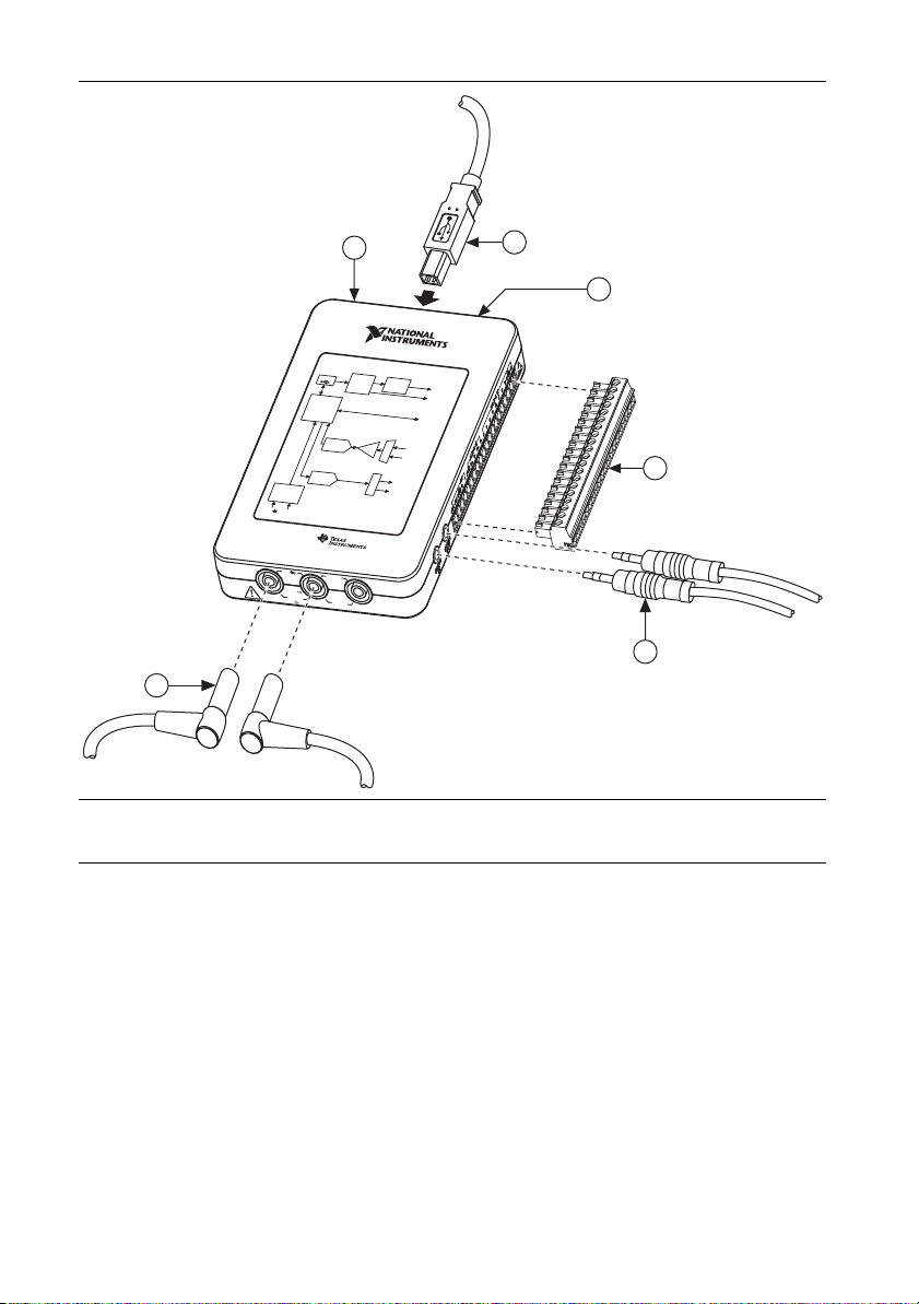
Figure 3. NI myDAQ Connection Diagram
1 A
M
A
X
6
0
V
2
0
V
rms
M
A
X
VΩ
A
6
1NI myDAQ
2USB Cable
3LED
1
2
3
NI myDAQ
Power Supply
U
SB
Current
DC-toDC
Limiter
Conver
t
e
r
±15 V
5
S
y
stem
Tim
in
g
Dig
ital
Controlle
r
An
a
log
I
An
a
log
-
to-Digit
a
l
Con
Gain
v
ert
e
r
A
n
a
log Output
D
ig
ital-
to-Analo
g
C
o
n
ve
r
ter
Dig
i
ta
l
Multimet
e
r
VΩ
A
N
I m
y
D
A
supp
V
Ω
2
0
MAX
H
I
AQ Sys
nalog
IC
s
lied b
y
Vr
m
s
1
A
CO
MAX
M
H
I
V
Input
/
O
u
tput
D
IO
n
p
ut
exer
AI
pl
ti
AUDIO
Mul
IN
ch
AO
t
i
Sw
AUDIO OUT
te
m
Dia
g
ram
4
5
4 20-Position Screw Terminal Connector
5 Audio Cable
6 DMM Banana Cable
8 | ni.com | NI myDAQ User Guide

Connecting Signals
AUDI OINAUDI O
OUT
Figure 4 shows the available audio, AI, AO, DIO, GND, and power signals accessed through the
3.5 mm audio jacks and screw terminal connections. Refer to Table 1 for descriptions of these
signals.
Cautions Signal wires must be securely affixed and screwed down in the screw
terminal connector to ensure proper connection.
To ensure the specified EMC performance:
• The length of any wire or cable connected to the 20-pin screw terminal
connector must be no longer than 0.3 m (1 ft).
• The length of any wire or cable connected to the Audio or DMM ports must be
no longer than 3 m (10 ft).
Figure 4. NI myDAQ 20-Position Screw Terminal I/O Connector
Table 1. Screw Terminal Signal Descriptions
Signal
Name
AUDIO IN — Input Audio Input—Left and right audio inputs
Reference Direction Description
on a stereo connector
AUDIO OUT — Output Audio Output—Left and right audio
outputs on a stereo connector
+15V/-15V AGND Output +15 V/-15 V power supplies
AGND — — Analog Ground—Reference terminal for
AI, AO, +15 V, and -15 V
AO 0/AO 1 AGND Output Analog Output Channels 0 and 1
AI 0+/AI 0-;
AGND Input Analog Input Channels 0 and 1
AI 1+/AI 1-
DIO <0..7> DGND Input or
Output
Digital I/O Signals—General-purpose
digital lines or counter signals
DGND — — Digital Ground—Reference for the DIO
lines and the +5 V supply
5V DGND Output 5 V power supply
NI myDAQ User Guide | © National Instruments | 9
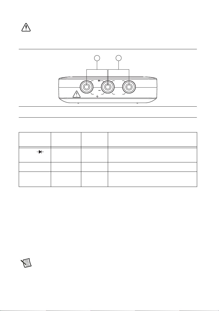
Figure 5 shows the DMM connections on the NI myDAQ. Table 2 describes these signals.
1 A A
MAX
6
0 V
20 Vrms
MAX
A
V
Ω
Caution 60 VDC/20 Vrms maximum. Do not plug digital multimeter probes into
circuits with Hazardous Voltages, such as wall outlets.
Figure 5. Connections for DMM Measurements
MAX
2
HIHI COM
1
0 V
20 Vrms
MAX
1 Connectors for Voltage/Resistance/Diode/Continuity
2 Connectors for Current
Table 2. DMM Signal Descriptions
Signal
Name
Reference Direction Description
HI (VΩ ) COM Input Positive terminal for voltage, resistance,
and diode measurements
COM — — Reference for all DMM measurements
HI (A) COM Input Positive terminal for current measurements
(Fused: F 1.25 A 250 V Fast-Acting)
Connecting Analog Input Signals
When configuring the input channels and making signal connections, you must first determine
whether the signal sources are floating or ground referenced. The following sections describe
these two signal types.
Ground-Referenced Signal Sources
A ground-referenced signal source is connected to the building system ground, so it is already
connected to a common ground point with respect to the NI myDAQ device, assuming that the
computer is plugged into the same power system. Instruments or devices with nonisolated
outputs that plug into the building power system are ground-referenced signal sources.
Note Most laptop computers have isolated power supplies, and are consequently
not connected to the building ground system. In these cases, treat the analog input
signal as floating with respect to NI myDAQ.
10 | ni.com | NI myDAQ User Guide

The difference in ground potential between two instruments connected to the same building power
+
–
+
–
AI+
AGND
Signal Source
AI–
+
–
AI+
AGND
Signal Source
R
source
>100
Ω
AI–
+
–
system is typically between 1 and 100 mV. This difference can be much higher if power
distribution circuits are improperly connected. If a grounded signal source is improperly measured,
this difference might appear as a measurement error. Connect the differential analog inputs across
the signal source and do not connect the NI myDAQ AGND pin to the grounded source.
Figure 6. Ground-Referenced Differential Connection
Floating Signal Sources
A floating signal source is not connected to the same ground reference as NI myDAQ, but
instead has an isolated reference point. Some examples of floating signal sources are
battery-powered devices, outputs of transformers, thermocouples, optical isolator outputs, and
isolation amplifiers. An instrument or device that has an isolated output is a floating signal
source. You must connect the ground reference of a floating signal to an NI myDAQ AGND pin
through a bias resistor or jumper wire to establish a local or onboard reference for the signal.
Otherwise, the measured input signal varies as the source floats out of the common-mode input
range.
The easiest way to reference the source to AGND is to connect the positive side of the signal to
AI+ and connect the negative side of the signal to AGND as well as to AI- without using
resistors. This connection works well for DC-coupled sources with low source impedance (less
than 100 Ω).
Figure 7. Differential Connections for Floating Signal Sources without Resistors
For larger source impedances, however, this connection leaves the differential signal path
significantly off balance. Noise that couples electrostatically onto the positive line does not
couple onto the negative line because it is connected to ground. This noise appears as a
differential-mode signal instead of a common-mode signal, and thus appears in your data. In this
case, instead of directly connecting the negative line to AGND, connect the negative line to
AGND through a resistor that is about 100 times the equivalent source impedance. The resistor
puts the signal path nearly in balance, so that about the same amount of noise couples onto both
NI myDAQ User Guide | © National Instruments | 11
connections, yielding better rejection of electrostatically coupled noise. This configuration does
+
–
+
–
AI+
AGND
Signal Source
R
source
>100
Ω
AI–
+
–
+
–
AI+
AGND
Signal Source
R
source
>100
Ω
AI–
not load down the source.
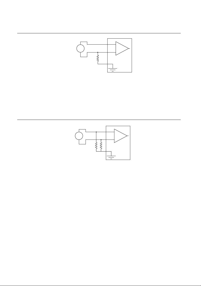
Figure 8. Differential Connections for Floating Signal Sources with a Single Resistor
You can fully balance the signal path by connecting another resistor of the same value between
the positive input and AGND, as shown in Figure 9. This fully balanced configuration offers
slightly better noise rejection, but has the disadvantage of loading the source down with the
series combination (sum) of the two resistors. If, for example, the source impedance is 2 kΩ and
each of the two resistors is 100 kΩ, the resistors load down the source with 200 kΩ and produce
a -1% gain error.
Figure 9. Differential Connections for Floating Signal Sources with Two Resistors
Both positive and negative analog input lines require a DC path to ground in order for the
instrumentation amplifier to work. If the source is AC coupled (capacitively coupled), a resistor
is needed between the positive input and AGND. If the source has low impedance, choose a
resistor that is large enough not to significantly load the source but small enough not to produce
significant input offset voltage as a result of input bias current (typically 100 kΩ to 1 MΩ). In
this case, connect the negative input directly to AGND. If the source has high output impedance,
balance the signal path as previously described using the same value resistor on both the positive
and negative inputs.
12 | ni.com | NI myDAQ User Guide
 Loading...