

National Instruments MXI-Express x4, MXI PCIe-8372, MXI PCIe-8371, MXI PCIe-8374, MXI PCIe-8370 Setup Manual
Page 1

Artisan Technology Group is your source for quality
new and certied-used/pre-owned equipment
• FAST SHIPPING AND
DELIVERY
• TENS OF THOUSANDS OF
IN-STOCK ITEMS
• EQUIPMENT DEMOS
• HUNDREDS OF
MANUFACTURERS
SUPPORTED
• LEASING/MONTHLY
RENTALS
• ITAR CERTIFIED
SECURE ASSET SOLUTIONS
SERVICE CENTER REPAIRS
Experienced engineers and technicians on staff
at our full-service, in-house repair center
Instra
Remotely inspect equipment before purchasing with
our interactive website at www.instraview.com
Contact us: (888) 88-SOURCE | [email protected] | www.artisantg.com
SM
REMOTE INSPECTION
View
WE BUY USED EQUIPMENT
Sell your excess, underutilized, and idle used equipment
We also offer credit for buy-backs and trade-ins
www.artisantg.com/WeBuyEquipment
LOOKING FOR MORE INFORMATION?
Visit us on the web at www.artisantg.com for more
information on price quotations, drivers, technical
specications, manuals, and documentation
Page 2

Set Up Your MXI -Express x4
™
System
This document explains what you will need to set up various
MXI-Express x4 hardware configurations.
The products covered by this guide are the NI PCIe-8371/8372 and
NI PXIe-8370/8374. For the remainder of this manual the term
MXI-Express x4 product refers to any of these products.
Additional compatible products are included in subsequent tables, but are
not covered in this manual.
Terminology
The following terms may be used throughout this document:
• Host PC—A host computer with at least one PCI Express x4 or wider
slot available.
Note Using a PCI Express slot wider than x4 may result in negotiation down to x1 width,
and therefore limiting bandwidth. This is uncommon in newer PCs.
• Expansion Chassis—An expansion chassis of any of the following
types:
– CompactPCI Express chassis
– PXI Express chassis
– NI HDD RAID
• MXI-Express x4 copper cable—Standard PCI Express specification
compliant cable with x4 PCIe connectors.
Note Refer to the Cabling section for details. Most MXI-Express kits include the cable,
but not all.
• Host Board—The MXI-Express x4 board of a cabled pair of boards
that is closer to the CPU.
Artisan Technology Group - Quality Instrumentation ... Guaranteed | (888) 88-SOURCE | www.artisantg.com
Page 3
• Target Board—The MXI-Express x4 board of a cabled pair of boards
that is farther from the CPU.
• Cabled Pair—Two MXI-Express x4 boards that are connected with a
single cable.
Connecting a PC to an Expansion Chassis
Using a MXI-Express x4 Copper Cable
Refer to the Terminology section for more detail on the items in this list.
Equipment Needed
❑ Host PC
❑ Expansion chassis
❑ MXI-Express x4 copper cable
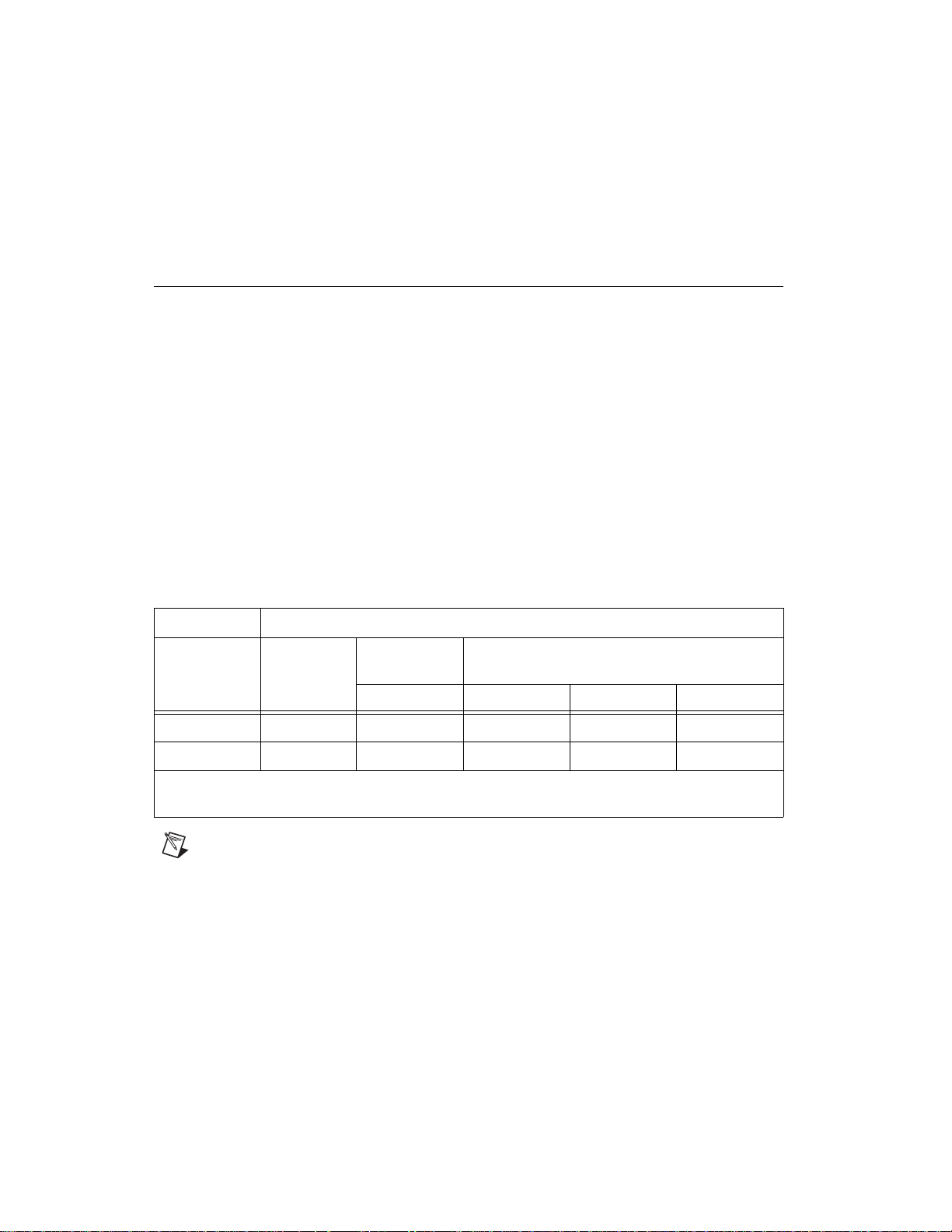
❑ A MXI-Express x4 host board and target board that is appropriate for
the host system slot and target chassis. Refer to Table 1 for more
information.
Table 1. MXI-Express x4 Connectivity Support from a Host PC Using a x4 Copper Cable
From Host Ta rg et s
PXI Express
Chassis
Slot Type Product
PCI Express x4 NI PCIe-8371
PCI Express x4 NI PCIe-8372
Note: For installation instructions and other information about the NI HDD series of products, refer to
their respective user manuals.
Note For full PXI or PXI Express functionality, refer to the Software Installation and
Configuration section for more information.
Set Up Your MXI-Express x4 System 2 ni.com
NI PXIe-8370 NI HDD-8263 NI HDD-8264 NI HDD-8265
HDD RAID
Artisan Technology Group - Quality Instrumentation ... Guaranteed | (888) 88-SOURCE | www.artisantg.com
Page 4
Connecting Additional Expansion Chassis to a System
Using a MXI-Express x4 Copper Cable
Refer to the Terminology section for more detail on the items in this list.
Equipment Needed
❑ Chassis to daisy-chain from
❑ Expansion chassis to daisy-chain to
❑ MXI-Express x4 copper cable
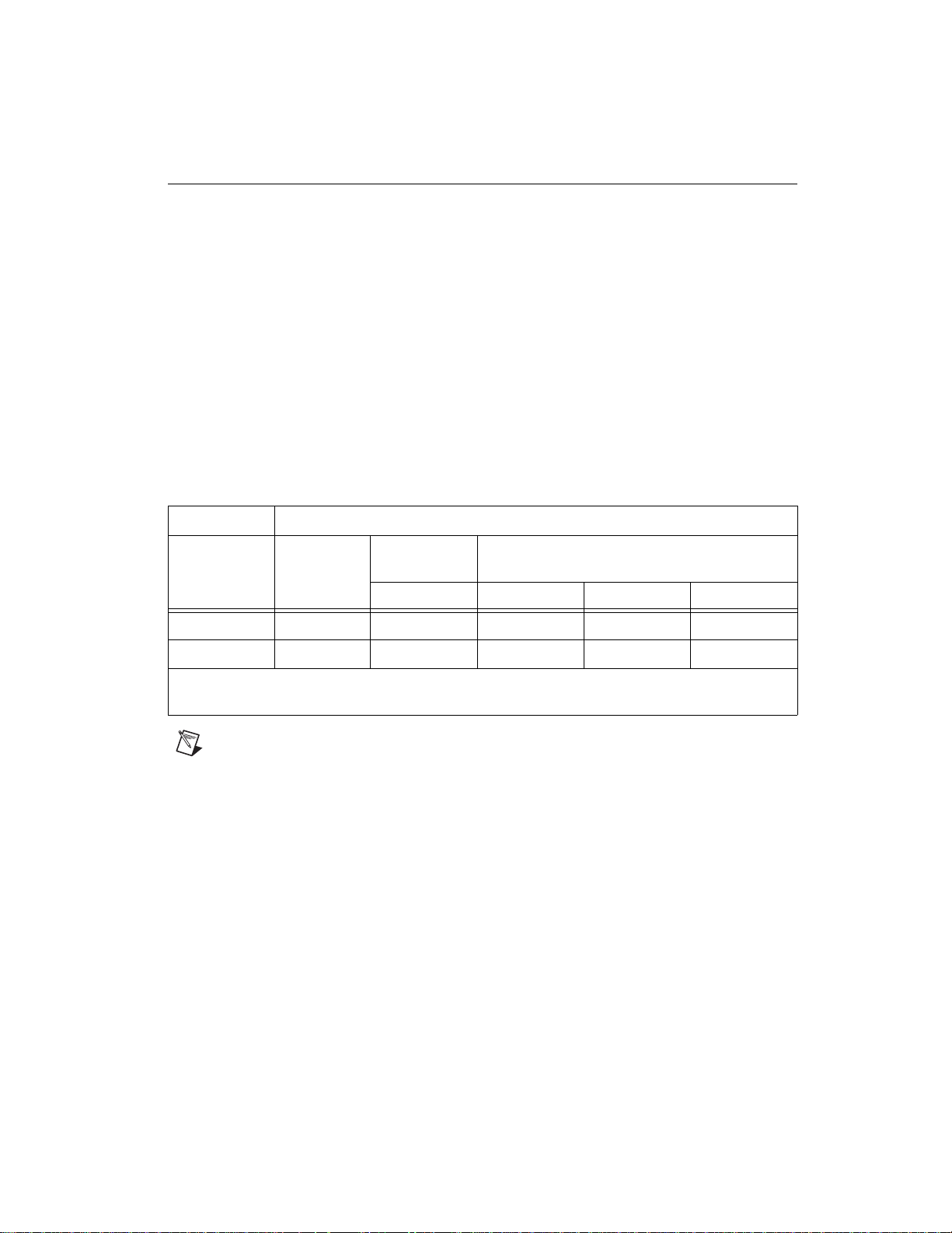
❑ A MXI-Express x4 host board and target board that is appropriate for
the host system slot and target chassis. Refer to Table 2 for more
information.
Table 2. MXI-Express x4 Connectivity Support from a Chassis Using a x4 Copper Cable
From Chassis Ta rg et s
PXI Express
Chassis
HDD RAID
Slot Type Product
PXI Express x4 NI PXIe-8374
PXI Express x4 NI 8262 —
Note: For installation instructions and other information about the NI HDD series of products, refer to
their respective user manuals.
Note For full PXI or PXI Express functionality, refer to the Software Installation and
Configuration section of for more information.
NI PXIe-8370 NI HDD-8263 NI HDD-8264 NI HDD-8265
© National Instruments Corporation 3 Set Up Your MXI-Express x4 System
Artisan Technology Group - Quality Instrumentation ... Guaranteed | (888) 88-SOURCE | www.artisantg.com
Page 5

Installation and Configuration
This section explains how to unpack, install, and configure the
MXI-Express x4 hardware and software.
Unpacking
Your MXI-Express x4 cards are shipped in antistatic packages to prevent
electrostatic damage (ESD) to the devices. ESD can damage several
components on the device.
Caution Never touch the exposed pins of connectors. Doing so may damage the device.
To avoid such damage in handling the device, take the following
precautions:
• Ground yourself using a grounding strap or by holding a grounded
object.
• Touch the antistatic package to a metal part of the computer chassis
before removing the device from the package.
Remove the device from the package and inspect the device for loose
components or any sign of damage. Notify NI if the device appears
damaged in any way. Do not install a damaged device into the computer or
into a PXI Express or CompactPCI Express chassis.
Store the device in the antistatic envelope when not in use.
Set Up Your MXI-Express x4 System 4 ni.com
Artisan Technology Group - Quality Instrumentation ... Guaranteed | (888) 88-SOURCE | www.artisantg.com
Page 6

Hardware Installation
The following are general instructions for installing the MXI-Express x4
cards. Consult your computer user manual or technical reference manual
for specific instructions and warnings.
Installing an NI PCIe-8371/8372
Complete the following steps to install the NI PCIe-8371/8372 in your
computer.
1. Power off your computer.
Caution To protect both yourself and the computer from electrical hazards, your computer
should remain off until you finish installing all hardware as instructed.
2. Remove the top cover or access port to the PCI Express expansion
slots.
3. Touch the metal part of the power supply case inside the computer to
discharge any static electricity that might be on your clothes or body.
4. Unplug the computer and wait 30 seconds to allow the energy stored
in the computer’s power supply to fully dissipate.
5. Select any available PCI Express expansion slot (x4 or wider).
Note Using a PCI Express slot wider than x4 may result in negotiation down to x1 width,
which will reduce throughput performance. This is rare in modern systems.
Note The BIOS or motherboard may not support the NI PCIe-8371/8372 in a slot intended
for a graphics card.
Note Not all PCI Express expansion slots that have x4 or wider physical connectors are
electrically capable of x4 PCI Express operation. Check with the motherboard
manufacturer to verify that the slot is capable of x4 PCI Express operation.
6. Locate the metal bracket that covers the cut-out in the back panel of the
computer for the slot you have selected. Remove and save the
bracket-retaining screw and the bracket cover.
7. Line up the NI PCIe-8371/8372 with the slot on the back panel. Slowly
lower the NI PCIe-8371/8372 until its card-edge connector is resting
on the expansion slot receptacle. Using slow, evenly distributed
pressure, press the NI PCIe-8371/8372 straight down until it seats in
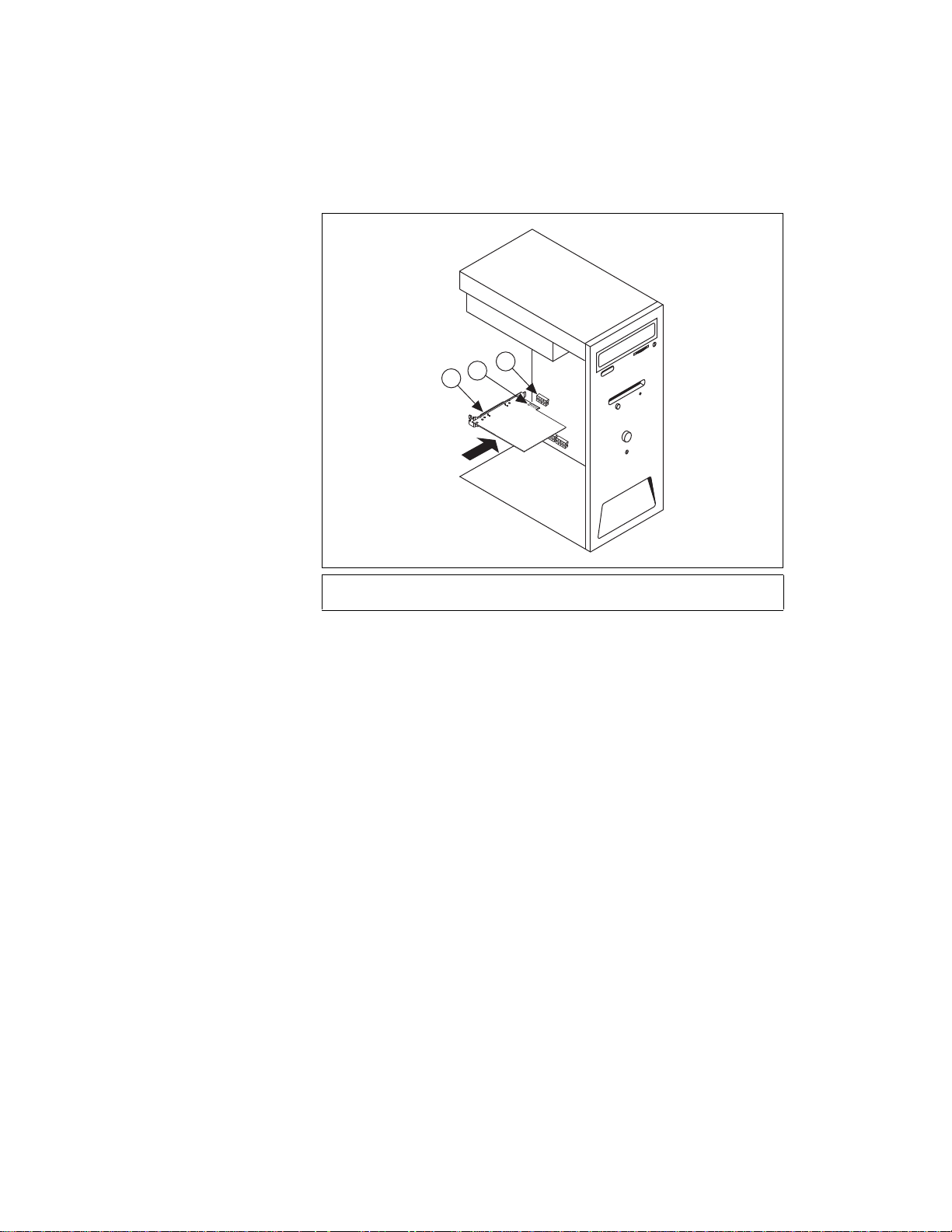
the expansion slot, as shown in Figure 1.
8. Secure the NI PCIe-8371/8372 to the back panel rail using a bracket
retaining screw.
© National Instruments Corporation 5 Set Up Your MXI-Express x4 System
Artisan Technology Group - Quality Instrumentation ... Guaranteed | (888) 88-SOURCE | www.artisantg.com
Page 7
9. Replace the computer cover.
1
3
2
10. Plug the computer back in.
1 NI PCIe-8371/8372
2 PCI Express x4 Card-Edge Connector
Figure 1. Installing the NI PCIe-8371/8372
3 PCI Express Slot (x4 or wider)
Installing the Low-Profile Bracket on the NI PCIe-8371 (Optional)
To install the NI PCIe-8371 in a host computer that requires a low-profile
height card, the front bracket must be replaced with the low-profile bracket
included with your kit. Complete the following steps to replace the bracket.
1. Remove the standard height front bracket already installed on your
NI PCIe-8371 card by removing the two 4-40 × 1/4 inch Phillips head
screws that attach the bracket to the card. Note that the two mounting
tabs for the standard height bracket rest against the front side of the
card, which is the side upon which the cable receptacle connector
housing rests. Set the two screws aside to re-use when installing the
low-profile bracket.
Set Up Your MXI-Express x4 System 6 ni.com
Artisan Technology Group - Quality Instrumentation ... Guaranteed | (888) 88-SOURCE | www.artisantg.com
Page 8
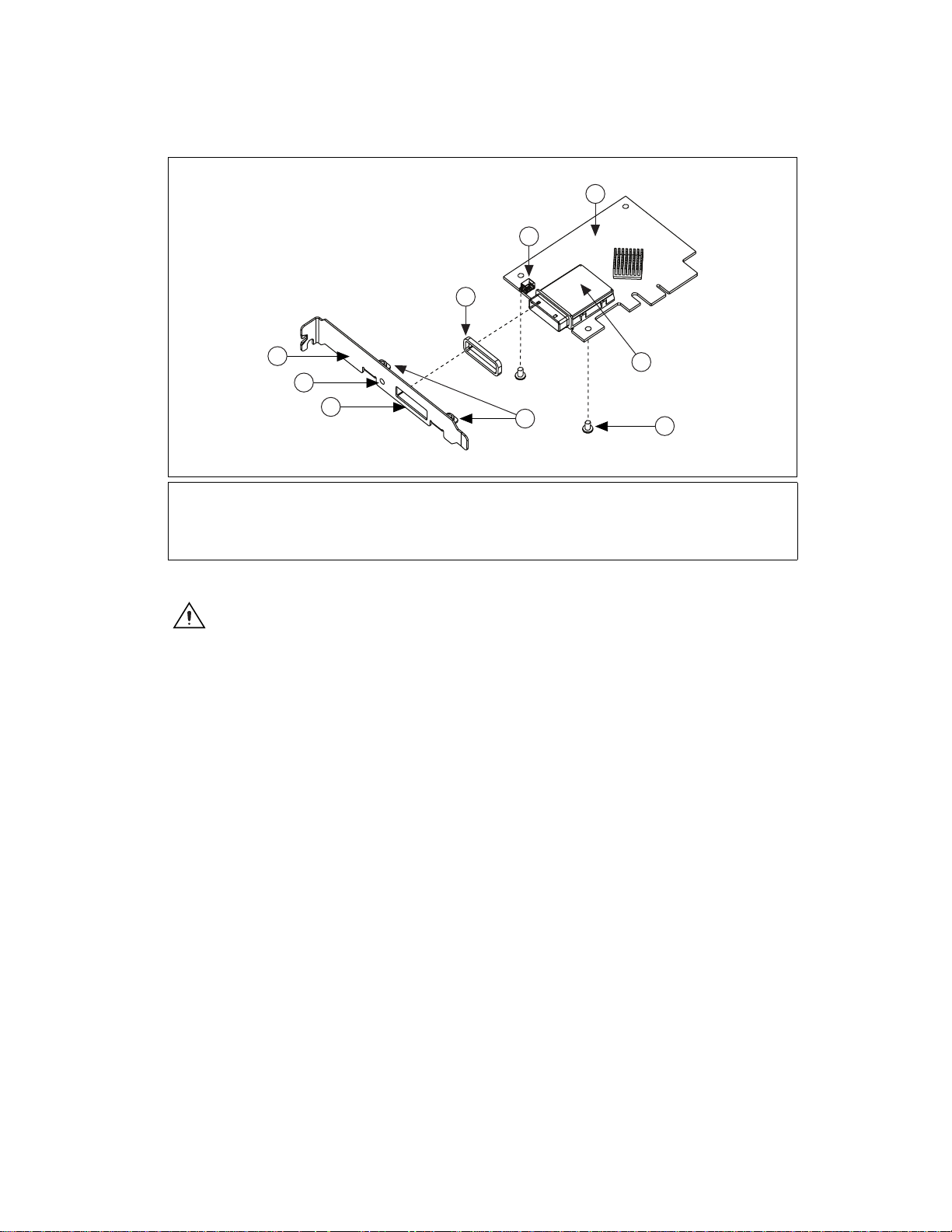
1 Standard Height Bracket
4
1
5
9
8
7
6
2
3
2EMI Gasket
3LED
4 Front Side of Card
5 Connector Shield
6 4-40 1/4 in. Phillips Head Screws (x2)
7 Mounting Tabs
8 Bracket Hole for Connector Shield
9 Bracket Hole for LED
Figure 2. Removing the Standard Height Bracket from the NI PCIe-8371
Caution
When removing the bracket, be careful not to remove or lose the EMI gasket on
the cable receptacle connector housing.
2. Fit the low-profile bracket onto the NI PCIe-8371. Note that the
two mounting tabs that the screws thread into rest against the back side
of the card for the low-profile bracket. Ensure that the front bracket
LED bulb is situated in the display hole correctly.
3. Align the mounting holes on the card with the threaded holes on the
mounting tabs of the bracket, and insert the screws from the front side.
4. Tighten each screw to a maximum torque of 3.6 lb · in. (0.407 N · m).
© National Instruments Corporation 7 Set Up Your MXI-Express x4 System
Artisan Technology Group - Quality Instrumentation ... Guaranteed | (888) 88-SOURCE | www.artisantg.com
Page 9
Installing an NI PXIe-8370 or NI PXIe-8374
H
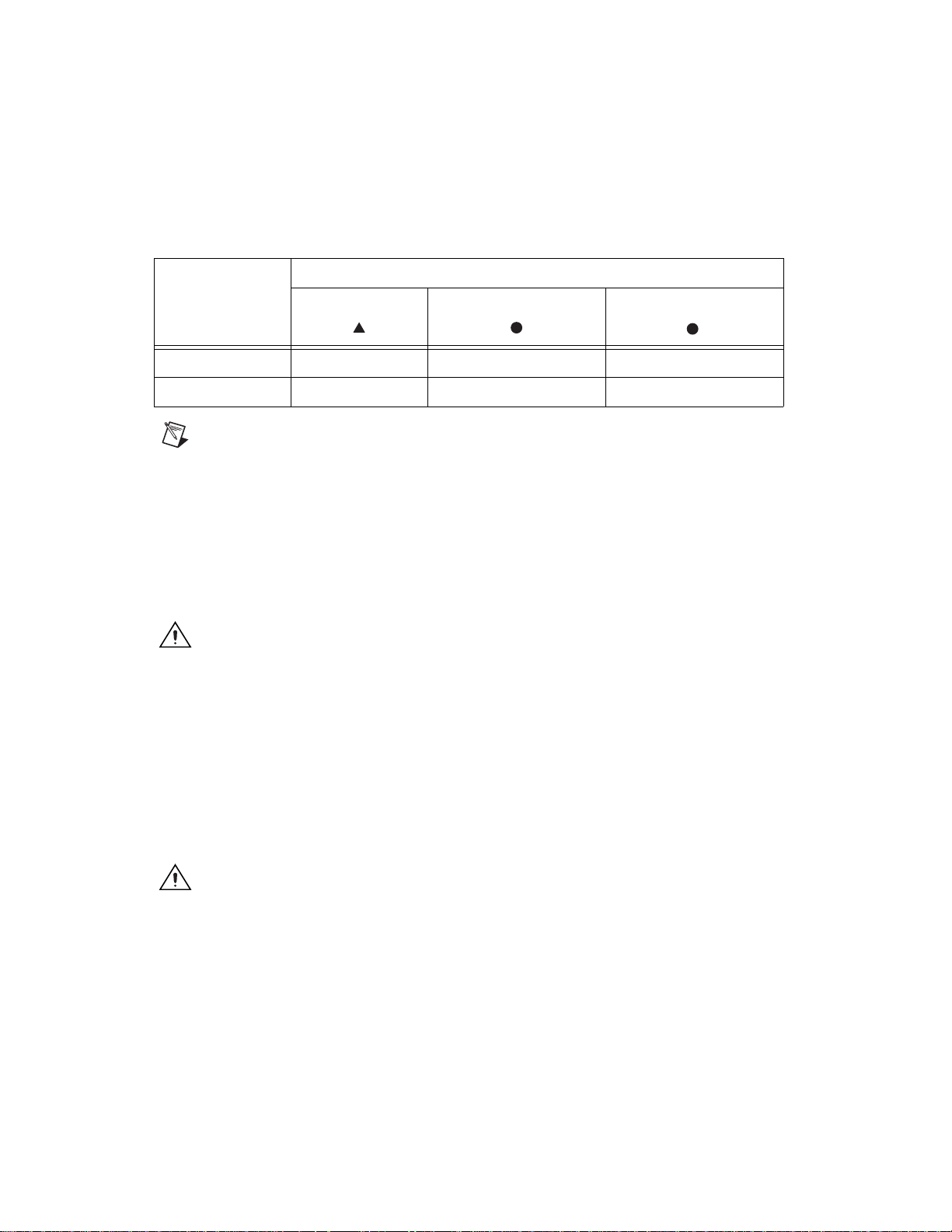
Table 3 provides information on which PXI Express MXI-Express x4
boards are compatible with which chassis slot types.
Table 3. NI MXI-Express x4 PXI Express Board Slot Type Compatibility
PXI Express Chassis
NI PXI Express
Controller Peripheral Hybrid
Board
NI PXIe-8370 — —
NI PXIe-8374 —
Note For this section, all of the above products will be referred to as an “NI PXI Express
board”.
Complete the following steps to install the NI PXI Express board in your
PXI Express or CompactPCI Express chassis.
1. Power off your PXI Express or CompactPCI Express chassis, but leave
it plugged in while installing the NI PXI Express board. The power
cord grounds the chassis and protects it from electrical damage while
you install the module.
Caution To protect both yourself and the chassis from electrical hazards, leave the chassis
off until you finish installing the NI PXI Express board.
2. Remove or open any doors or covers blocking access to the slot in
which you intend to install the NI PXI Express board.
3. Touch a metal part of the chassis to discharge any static electricity that
might be on your clothes or body.
4. Make sure the injector/ejector handle is in its downward position.
Be sure to remove all connector packaging and protective caps from
retaining screws on the module. Align the NI PXI Express board with
the card guides on the top and bottom of the system controller slot.
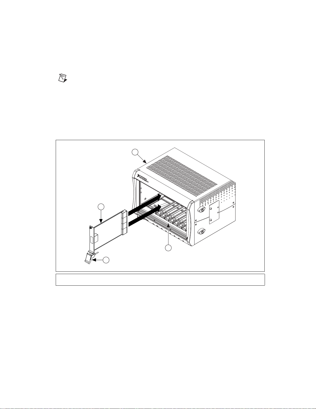
Caution Do not raise the injector/ejector handle as you insert the NI PXI Express board.
It will not insert properly unless the handle is in its downward position so that it does not
interfere with the injector/ejector rail on the chassis, as shown in Figure 3.
5. Hold the handle as you slowly slide the module into the chassis until
the handle catches on the injector/ejector rail.
Set Up Your MXI-Express x4 System 8 ni.com
Artisan Technology Group - Quality Instrumentation ... Guaranteed | (888) 88-SOURCE | www.artisantg.com
Page 10
6. Raise the injector/ejector handle until the module firmly seats into the
backplane receptacle connectors. The front panel of the NI PXI
Express board should be even with the front panel of the chassis.
Note LEDs on the back side of the NI PXIe-8370 will light, indicating the presence of 5 V
auxiliary power. Refer to the LED Indicators section for details.
7. Tighten the bracket-retaining screws on the top and bottom of the front
panel to secure the NI PXI Express board to the chassis.
8. Replace or close any doors or covers to the chassis.
Figure 3 shows an NI PXI Express board just before installation in the
system controller slot of a National Instruments PXI Express chassis.
1
NI PXIe-1062Q
2
4
3
1 PXI Express/CompactPCI Express Chassis
2 NI PXI Express board
3 Ejector Handle in Down Position
4 Injector/Ejector Rail
Figure 3. Example NI PXI Express Board Installation Into a PXI Express Chassis
© National Instruments Corporation 9 Set Up Your MXI-Express x4 System
Artisan Technology Group - Quality Instrumentation ... Guaranteed | (888) 88-SOURCE | www.artisantg.com
Page 11
Cabling
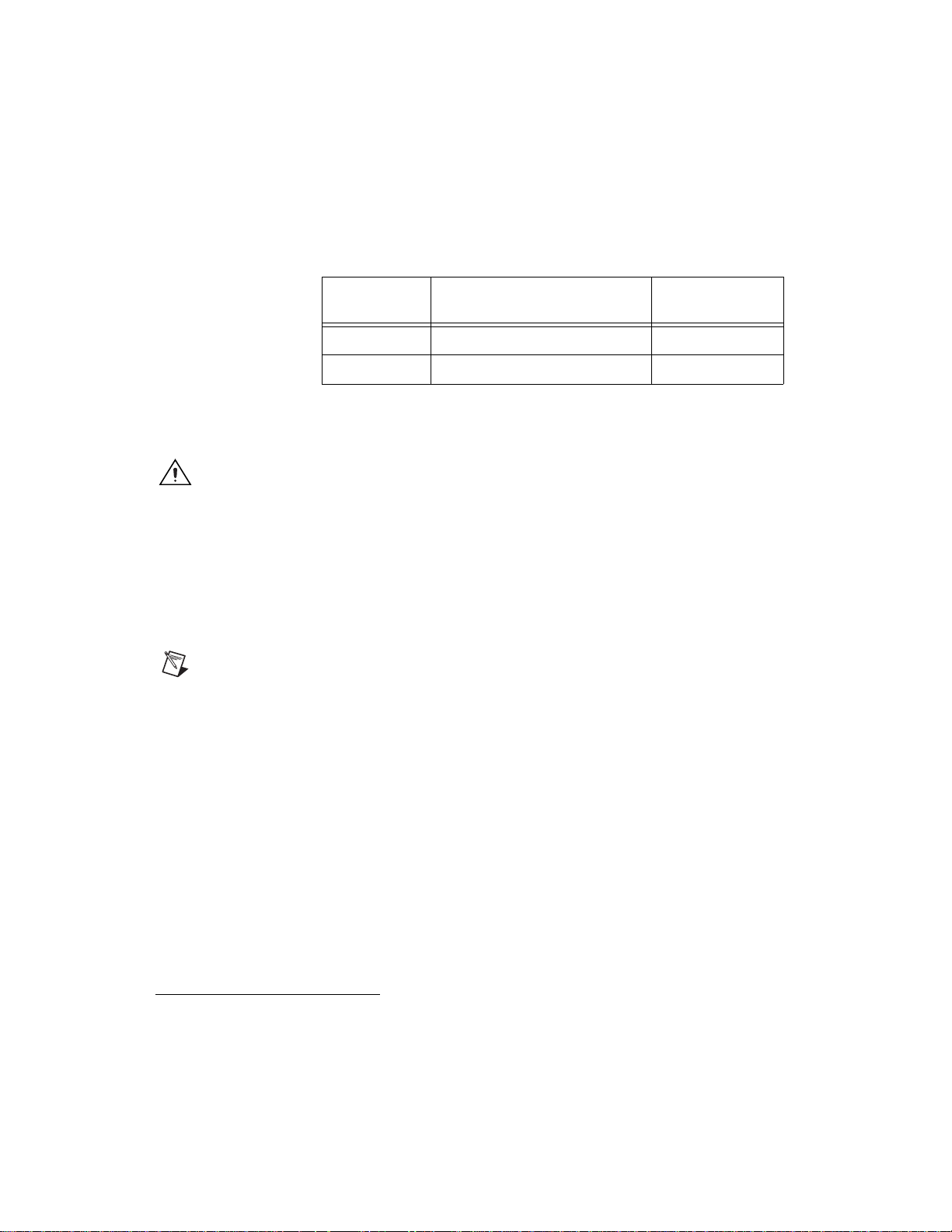
MXI-Express x4 is available with copper cables of various lengths. Table 4
shows the MXI-Express x4 copper cables
Instruments.
Table 4. National Instruments MXI-Express x4 Copper Cables
Cable Length
(Meters)
3 m MXI-Express x4 copper cable 779725-03
7 m MXI-Express x4 copper cable 779725-07
Connect the MXI-Express x4 cable to both MXI-Express x4 cards. The
cables have no polarity, so either end may be connected to either card.
Caution Do not remove the cable after the system is powered on. Doing so can hang
or cause errors in applications communicating with devices behind MXI-Express x4. If a
cable becomes unplugged, plug it back into the system. (You may need to restart your
computer.)
Powering On the MXI-Express x4 System
1. Power-on all of the expansion chassis in any order you choose.
2. Power-on the host.
1
available from National
Description Part Number
Note There are no requirements on how MXI-Express x4 expansion chassis are powered
up relative to each other, as long as they are all on before the computer is powered on.
3. Observe the LED status on the NI PCIe-8371, NI PCIe-8372,
NI PXIe-8370 and NI PXIe-8374 where applicable. A properly
connected and powered up system should report a valid link and power
status on all of these boards once the host PC is powered on. Refer to
the LED Indicators section for more information.
Typical PCI-PCI bridges and switches are used to add PCI devices to a PCI
hierarchy in which all the bridges and devices are contained within a single
chassis. Because of this, BIOSes and operating systems make the
assumption that all PCI devices in the entire hierarchy will be available as
soon as code execution begins at power-up time. This assumption means
that all of the expansion chassis must be turned on before the host PC for
the BIOS and OS to correctly configure a MXI-Express x4 system.
1
For more information, refer to the Terminology section.
Set Up Your MXI-Express x4 System 10 ni.com
Artisan Technology Group - Quality Instrumentation ... Guaranteed | (888) 88-SOURCE | www.artisantg.com
Page 12
Powering Off the MXI-Express x4 System
Because operating systems and drivers commonly make the assumption
that PCI devices will be present in the system from power-up to
power-down, it is important to not power off the expansion chassis until
after the host PC is powered off. Powering off the expansion chassis while
the host is still on can cause crashes or hangs. However, once the host pc is
powered off, the order that the expansion chassis are powered off is not
important.
Note To power down the chassis while the host computer or host chassis is on, you may
need to hold the power button for at least four seconds. However, this behavior cannot be
guaranteed.
LED Indicators
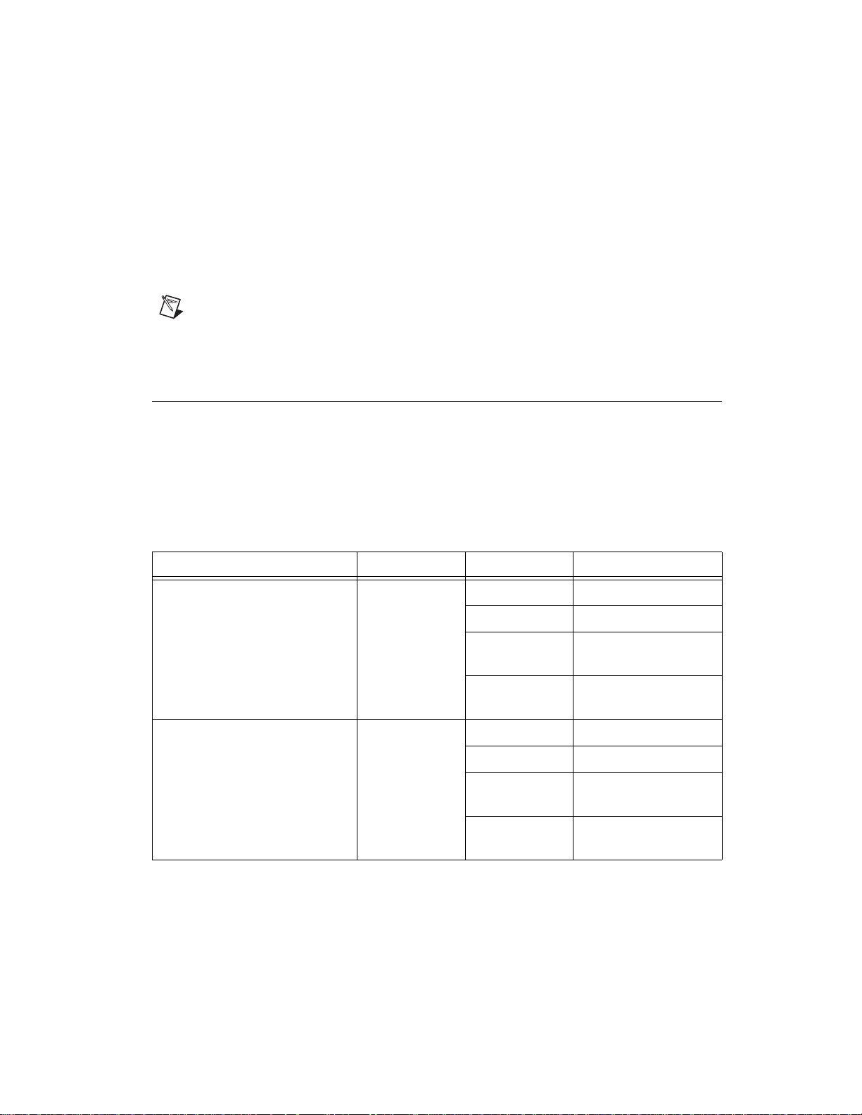
The LEDs on MXI-Express x4 cards give status information about power
supplies and link state. The NI PCIe-8371 and NI PXIe-8374 have
one tri-color LED on the panel, indicating power and link status. The
NI PCIe-8372 has two tri-color LEDs on the panel, indicating power and
link status for each port. The NI PXIe-8370 has two LEDs, one for power
supply status and one for link state.
Table 5. LED Status Descriptions of MXI-Express x4 Products
Board LED Color Meaning
NI PCIe-8371 (199994x-01L)
NI PXIe-8374 (193970x-02L)
NI PCIe-8372 (194591x-01L) PWR/LINK Off Power is off
© National Instruments Corporation 11 Set Up Your MXI-Express x4 System
PWR/LINK Off Power is off
Blinking Red Power is out of spec
Solid Amber Power is within spec;
no link to chassis
Solid Green Power is within spec;
link established
Solid Red Power is out of spec
Solid Amber Power is within spec;
no link to chassis
Solid Green Power is within spec;
link established
Artisan Technology Group - Quality Instrumentation ... Guaranteed | (888) 88-SOURCE | www.artisantg.com
Page 13
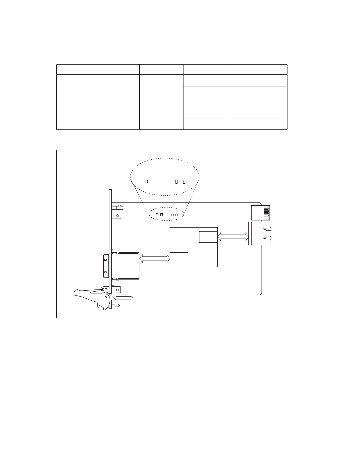
Table 5. LED Status Descriptions of MXI-Express x4 Products (Continued)
Cabled
PCI-Express x4
Copper
PCIe Switch
PCIe Gen 1 x4
4
0
Link Good
4
0
Link Activity
Por t 0
Por t 4
PCIe Gen 1 x4
Board LED Color Meaning
NI PXIe-8370 (194402x-02) PWR Off No power
Blinking Red Power is out of spec
Solid Green Power is within spec
LINK Off Link not established
Solid Green Link established
Refer to Figure 4 for onboard LED locations.
Figure 4. NI PXIe-8374 (193970x-02L) Onboard LED Locations
Link Good LEDs—LEDs that indicate a successful cable link (LED 0) and
backplane link (LED 4).
Link Activity LEDs—LEDs that indicate link activity on the cable link
(LED 0) and the backplane link (LED 4).
Set Up Your MXI-Express x4 System 12 ni.com
Artisan Technology Group - Quality Instrumentation ... Guaranteed | (888) 88-SOURCE | www.artisantg.com
Page 14
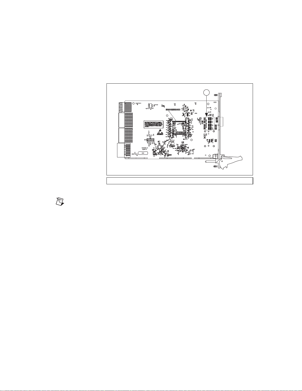
The NI PXIe-8370 also has a vertical column of 16 LEDs on the back panel
1
of the card near the front connector, as shown in Figure 5. These LEDs
provide additional information about the link status of the PCI Express
lanes on the module to the backplane. Each group of four LEDs
corresponds to one of the four PCI Express links to the backplane.
1 Back Panel LEDs
Figure 5. NI PXIe-8370 Back Side LED Locations
Notes
If you are using a chassis (such as the NI PXIe-1062) that directly links the
PXI Express board, the LEDs to that slot will not illuminate until you have a PXI Express
board installed and linked.
If you are using the NI PXIe-1062 chassis, you will notice that the last group of LEDs has
an LED (PORT 3) illuminated even if no boards are populated in the slots. Since the
NI PXIe-1062 uses the last link for a PCI Express to PCI bridge for PXI communication,
this link should always be active. Different chassis topologies will give different default
behaviors. Contact your chassis’ manufacturer for more information on your chassis’
topology.
© National Instruments Corporation 13 Set Up Your MXI-Express x4 System
Artisan Technology Group - Quality Instrumentation ... Guaranteed | (888) 88-SOURCE | www.artisantg.com
Page 15

Software Installation and Configuration
Installation
MXI-Express x4 is based on PCI Express technology, using PCI Express
switches and/or bridges to enable control of a PXI Express chassis from a
PC or another PXI Express chassis with an available PCI Express or
PXI Express slot. This technology will be recognized as a collection of
PCI-to-PCI bridges to the operating system, and should automatically have
CompactPCI Express level support without any additional software.
Note For full PXI/PXI Express functionality such as chassis and controller identification,
trigger routing, and slot detection, install the PXI Platform Services software included with
your kit. This software also can be found at
PXI Platform Services.
ni.com/updates by searching for
For operating system support, refer to the KnowledgeBase
PXI Platform Services Operating System Support at
Configuring Your System
Note The following requires the PXI Platform Services software and
Measurement & Automation Explorer (MAX), included on your PXI Platform
Services CD or your driver CD.
For information on configuring your system in MAX, open MAX and
navigate to Help»Help Topics»PXI.
53399AQ7,
ni.com/kb.
Set Up Your MXI-Express x4 System 14 ni.com
Artisan Technology Group - Quality Instrumentation ... Guaranteed | (888) 88-SOURCE | www.artisantg.com
Page 16

LabVIEW, National Instruments, NI, ni.com, the National Instruments corporate logo, and the Eagle
logo are trademarks of National Instruments Corporation. Refer to the Trademark Information at
ni.com/trademarks for other National Instruments trademarks. Other product and company
names mentioned herein are trademarks or trade names of their respective companies. For patents
covering National Instruments products/technology, refer to the appropriate location: Help»Patents
in your software, the patents.txt file on your media, or the National Instruments Patent Notice
at ni.com/patents. Refer to the Export Compliance Information at ni.com/legal/
export-compliance for the National Instruments global trade compliance policy and how to
obtain relevant HTS codes, ECCNs, and other import/export data.
© 2006–2011 National Instruments Corporation. All rights reserved.
371976C-01 Jul11
Artisan Technology Group - Quality Instrumentation ... Guaranteed | (888) 88-SOURCE | www.artisantg.com
Page 17

Artisan Technology Group is your source for quality
new and certied-used/pre-owned equipment
• FAST SHIPPING AND
DELIVERY
• TENS OF THOUSANDS OF
IN-STOCK ITEMS
• EQUIPMENT DEMOS
• HUNDREDS OF
MANUFACTURERS
SUPPORTED
• LEASING/MONTHLY
RENTALS
• ITAR CERTIFIED
SECURE ASSET SOLUTIONS
SERVICE CENTER REPAIRS
Experienced engineers and technicians on staff
at our full-service, in-house repair center
Instra
Remotely inspect equipment before purchasing with
our interactive website at www.instraview.com
Contact us: (888) 88-SOURCE | [email protected] | www.artisantg.com
SM
REMOTE INSPECTION
View
WE BUY USED EQUIPMENT
Sell your excess, underutilized, and idle used equipment
We also offer credit for buy-backs and trade-ins
www.artisantg.com/WeBuyEquipment
LOOKING FOR MORE INFORMATION?
Visit us on the web at www.artisantg.com for more
information on price quotations, drivers, technical
specications, manuals, and documentation
 Loading...