

National Instruments MON-10467 User Manual
USER GUIDE
MON-10467
MON-10467
12-Channel Wireless Vibration Measurement Device
This document explains how to install the MON-10467. You can use the MON-10467 to
wirelessly connect up to 12 sensors, such as piezoelectric accelerometers, proximity probes,
tachometers, voltage, and temperature, to your network without conduit for power or network
lines. This device is available in lithium battery, 24 V DC, and 120/220 V AC variants to
support your application’s requirements. Rated for outdoor use, the MON-10467 has a rugged

enclosure and a built-in mounting flange. With a five second data buffer per channel and full
waveform transmission, this device is ideal for applications that require wireless monitoring.
Note Read the MON-10467 Safety, Environmental, and Regulatory Information
document on ni.com/manuals before installing.
Note In this document, the MON-10467 (AC), MON-10467 (DC), and
MON-10467 (BATTERY) are referred to inclusively as the MON-10467. The
information in this document applies to all versions of the MON-10467 unless
otherwise specified.
Note The guidelines in this document are specific to the MON-10467. The other
components in the system might not meet the same safety ratings. Refer to the
documentation for each component in the system to determine the safety and EMC
ratings for the entire system.
Contents
Related Documentation.............................................................................................................3
Unpacking................................................................................................................................. 3
Kit Contents.............................................................................................................................. 3
What You Need to Get Started..................................................................................................4
Safety........................................................................................................................................ 5
Electromagnetic Compatibility Notices.................................................................................... 7
Parts Diagrams.......................................................................................................................... 8
MON-10467 with Door Closed.........................................................................................8
MON-10467 (AC) Parts Diagram.....................................................................................9
MON-10467 (DC) Parts Diagram...................................................................................10
MON-10467 (BATTERY) Parts Diagram.......................................................................11
Pinouts.....................................................................................................................................11
Analog Input Pinout........................................................................................................ 11
24 V DC Power Bus Terminals Pinout........................................................................... 12
Opening and Closing the Door................................................................................................13
Mounting.................................................................................................................................13
Installing the Antenna and Boot..............................................................................................14
Proximity Probe Drivers and Electronic Accessories............................................................. 15
Wiring......................................................................................................................................18
Wiring Guidelines........................................................................................................... 18
Using the Desiccant Kit.......................................................................................................... 26
MON-10401 Replacement Battery Pack for the MON-10467 (BATTERY)..........................28
Safety.............................................................................................................................. 28
Replacing the Battery Pack............................................................................................. 28
Battery Pack Recycling...................................................................................................29
Using the Reset Button........................................................................................................... 30
Where to Go Next................................................................................................................... 32
Product Certifications and Declarations................................................................................. 32
Worldwide Support and Services............................................................................................ 32
2 | ni.com | MON-10467 User Guide
Related Documentation
3
1 2 4 5 6
The following documents contain information about the MON-10467. To view them, go to
ni.com/manuals.
• MON-10467 Safety, Environmental, and Regulatory Information
• MON-10467 Specifications
For help using your device in InsightCM, refer to the InsightCM Help in software or online at
ni.com/r/insightcmhelp.
Unpacking
Notice Electrostatic Discharge (ESD) can damage the device. To prevent damage,
use industry-standard ESD prevention measures during unpacking, installation,
maintenance, and operation.
Notice Never touch exposed signal terminals, power terminals, or antenna
connector.
Remove the device from the package and inspect it for loose components or any other signs of
damage. Notify NI if the device appears damaged in any way. Do not install a damaged
device.
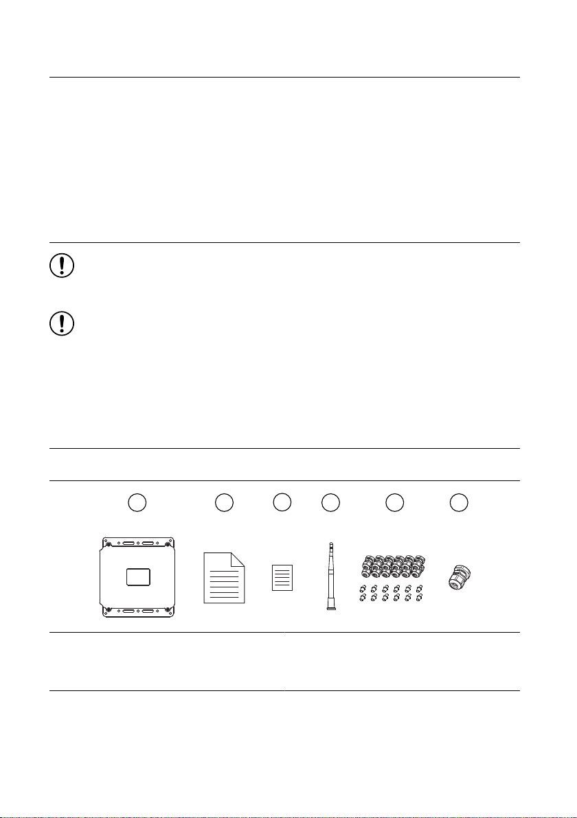
Kit Contents
MON-10467 (AC) and MON-10467 (DC) Kit Contents
1. MON-10467
2. MON-10467 Safety, Environmental, and
Regulatory Information
3. NI Monitoring Devices Card
4. 1 Antenna with weather-protective boot
5. 12 M16 Glands
6. 1 PG16 Gland
MON-10467 User Guide | © National Instruments | 3
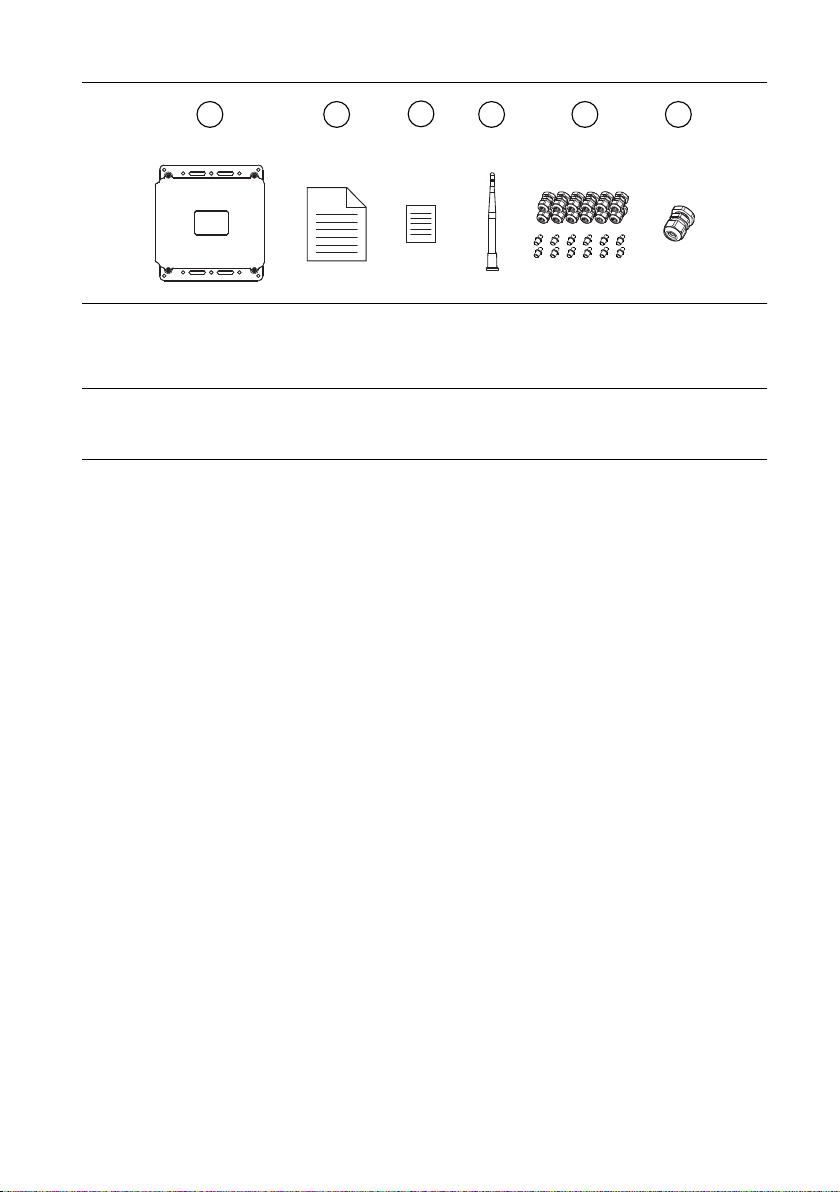
MON-10467 (BATTERY) Kit Contents
3
1 2 4 5 6
1. MON-10467
2. MON-10467 Safety, Environmental, and
Regulatory Information
3. NI Monitoring Devices Card
4. 1 Antenna with weather-protective boot
5. 12 M16 Glands
6. 1 M16 Gland
What You Need to Get Started
MON-10467 (AC)
Hardware needed:
• M6 to M8 bolts and nuts or 1/4 in. to 5/16 in. bolts and nuts
• Washers (recommended)
• M16 glands (supplied by NI)
• Plugs rated for Type 3 or greater ingress protection for unused ports
• PG16 gland (supplied by NI) or 0.5 in. conduit fitting
• Power cable with a smooth, round jacket and individual conductors up to 12 AWG that
comply with your local electrical code
Tools needed:
• 2.5 mm flat-blade screwdriver (your own or NI part number 786911-01)
• 19 mm deep socket or wrench
• 22 mm socket or wrench
• 27 mm deep socket
• 30 mm socket or wrench
• 24 mm socket or wrench
• (Optional) multi-prong actuation tool (WAGO part number 279-433)
• (Optional) 19 mm gland dome nut tightening tool (SEALCON part number S-1900-WR)
• (Optional) 24 mm gland dome nut tightening tool (SEALCON part number S-2400-WR)
4 | ni.com | MON-10467 User Guide

MON-10467 (DC)
Hardware needed:
• M6 to M8 bolts and nuts or 1/4 in. to 5/16 in. bolts and nuts
• Washers (recommended)
• M16 glands (supplied by NI)
• Plugs rated for Type 3 or greater ingress protection for unused ports
• PG16 gland (supplied by NI) or 0.5 in. conduit fitting
• Power cable with a smooth, round jacket and individual conductors up to 14 AWG that
comply with your local electrical code
Tools needed:
• 2.5 mm flat-blade screwdriver (your own or NI part number 786911-01)
• #2 Phillips screwdriver
• 19 mm deep socket or wrench
• 22 mm socket or wrench
• 27 mm deep socket
• 30 mm socket or wrench
• 24 mm socket or wrench
• (Optional) multi-prong actuation tool (WAGO part number 279-433)
• (Optional) 19 mm gland dome nut tightening tool (SEALCON part number S-1900-WR)
• (Optional) 24 mm gland dome nut tightening tool (SEALCON part number S-2400-WR)
MON-10467 (BATTERY)
Hardware needed:
• M6 to M8 bolts and nuts or 1/4 in. to 5/16 in. bolts and nuts
• Washers (recommended)
• M16 glands (supplied by NI)
• Plugs rated for Type 3 or greater ingress protection for unused ports
• Chassis ground cable with a smooth, round jacket and spade or ring lug
Tools needed:
• 2.5 mm flat-blade screwdriver (your own or NI part number 786911-01)
• #2 Phillips screwdriver
• 19 mm deep socket or wrench
• 22 mm socket or wrench
• (Optional) multi-prong actuation tool (WAGO part number 279-433)
• (Optional) 19 mm gland dome nut tightening tool (SEALCON part number S-1900-WR)
Safety
MON-10467 User Guide | © National Instruments | 5
Caution Observe all instructions and cautions in the user documentation. Using
the model in a manner not specified can damage the model and compromise the
built-in safety protection. Return damaged models to NI for repair.
Attention Suivez toutes les instructions et respectez toutes les mises en garde de la
documentation utilisateur. L'utilisation d'un modèle de toute autre façon que celle
spécifiée risque de l'endommager et de compromettre la protection de sécurité
intégrée. Renvoyez les modèles endommagés à NI pour réparation.
Caution The protection provided by the MON-10467 can be impaired if it is used
in a manner not described in the user documentation.
Attention La protection apportée par le MON-10467 risque d'être endommagée s'il
est utilisé d'une autre façon que celle décrite dans la documentation utilisateur.
Caution All wiring must be insulated for the highest voltage used.
Attention Tout le câblage doit être isolé pour la plus haute tension utilisée.
Caution An external circuit breaker box must be installed according to applicable
electrical codes by trained personnel to serve as the power disconnect when
installing the MON-10467 (AC). The circuit breaker box must be easy to reach and
marked as the power disconnect for the device.
Attention Un boîtier de disjoncteur externe doit être installé par du personnel
qualifié, conformément aux normes électriques en vigueur, afin de servir de
dispositif de coupure de courant lors de l'installation du MON-10467 (AC). Le
boîtier du disjoncteur doit être facilement accessible et marqué en tant que dispositif
de coupure de courant pour l'appareil.
Caution Disconnect external power to the MON-10467 (AC) and use the external
circuit breaker box to completely remove mains power before opening the device for
service.
Attention Débranchez l'alimentation externe du MON-10467 (AC) et utilisez le
boîtier de disjoncteur externe pour couper complètement l'alimentation secteur avant
d'ouvrir l'appareil pour l'entretien.
Caution Remove power to the MON-10467 (DC) before opening it for service.
Attention Mettez le MON-10467 (DC) hors tension avant de l'ouvrir pour
l'entretien.
Caution Conduit or gland fittings must be installed by trained personnel according
to applicable electrical standards and the torque specified by the manufacturer.
6 | ni.com | MON-10467 User Guide

Attention Les raccords de conduits ou presse-étoupe doivent être installés par du
personnel qualifié conformément aux normes électriques applicables et au couple
spécifié par le fabricant.
Electromagnetic Compatibility Notices
Refer to the following notices for cables, accessories, and prevention measures necessary to
ensure the specified EMC performance.
Notice For EMC declarations and certifications, and additional information, refer
to the Product Certifications and Declarations section.
Notice The length of the signal cable must be no longer than 30 m (100 ft).
Notice Operate this product only with shielded cables and accessories.
Notice The performance of this product can be disrupted if subjected to
Electrostatic Discharge (ESD) during operation. To prevent damage, industrystandard ESD prevention measures must be employed during installation,
maintenance, and operation.
MON-10467 User Guide | © National Instruments | 7
Parts Diagrams
MON-10467
1
2
3
3
3
3
2
4
5
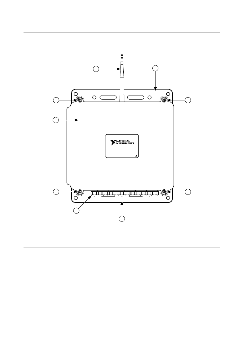
MON-10467 with Door Closed
1. Antenna
2. Mounting flanges
3. Captive screws
8 | ni.com | MON-10467 User Guide
4. Glands
5. Door
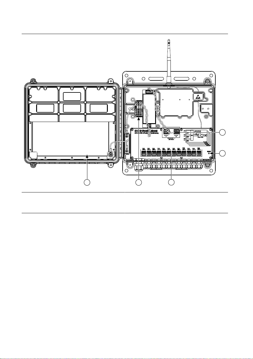
MON-10467 (AC) Parts Diagram
3
5
2
1
4
1. 24 V DC power bus terminals
2. Reset button
3. Analog input terminals
4. AC power input terminals
5. Door pocket for desiccant pack
MON-10467 User Guide | © National Instruments | 9
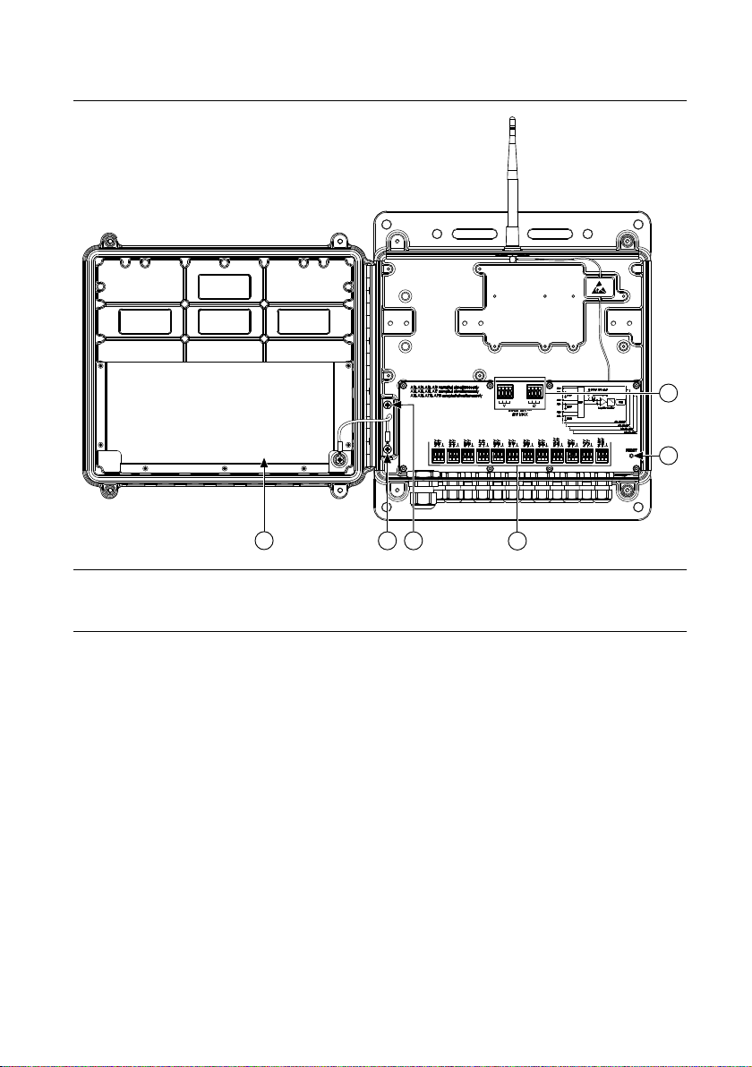
MON-10467 (DC) Parts Diagram
1
2
3
6
5
4
1. 24 V DC power bus terminals
2. Reset button
3. Analog input terminals
10 | ni.com | MON-10467 User Guide
4. Chassis ground screw
5. Ground shelf
6. Door pocket for desiccant pack
 Loading...