

Page 1

USER GUIDE
MID-7654/7652 S
This user guide describes the electrical and mechanical aspects of the
MID-7654/7652 servo power motor drive and describes how to use
the MID-7654/7652 with your motion controller.
Contents
Conventions ............................................................................................2
Introduction.............................................................................................2
What You Need to Get Started ............................................................... 3
Safety Information .................................................................................. 3
Front Panel Switches...............................................................................5
Host Bus Interlock Circuit ......................................................................6
Front Panel LEDs.................................................................................... 6
Amplifier Fault Output LEDs .......................................................... 7
Amplifier Inhibit LEDs.................................................................... 7
Limit Status LEDs ........................................................................... 7
Front Panel DIP Switch Settings............................................................. 8
Inhibit Input Polarity Setting ........................................................... 9
Inhibit Output Polarity Setting......................................................... 9
Limit Status LED Polarity Setting................................................... 10
Setting Continuous and Peak Current Limits .................................. 10
Setting Motor Inductance Levels..................................................... 13
Back Panel Connector Wiring.................................................................15
Terminal Block Wiring.................................................................... 17
Servo Motor Power Terminal Blocks....................................... 17
Rear Guard................................................................................ 19
Encoder Terminal Blocks ......................................................... 22
Limit Switch Terminal Blocks ................................................. 24
Breakpoint and Trigger Terminal Blocks................................. 25
Analog I/O Terminal Blocks .................................................... 25
Step and Direction Terminal Block ..........................................26
Cable Installation for CE Compliance .............................................27
Accessories Included for Optional Use...................................................28
Strain-Relief Bar Installation ........................................................... 28
Panel Mount Kit Installation............................................................ 29
ERVOPOWER
M
OTOR
D
RIVE
National Instruments™, NI™, and ni.com™ are trademarks of National Instruments Corporation. Product and company names mentioned herein are
trademarks or trade names of their respective companies.
322691B-01 Copyright © 2000, 2001 National Instruments Corp. All rights reserved. June 2001
Page 2

Modifying the Power Entry Module........................................................30
Replacing a Fuse...............................................................................30
Changing the Line Voltage...............................................................31
Amplifier/Driver Command Signals .......................................................31
Specifications...........................................................................................31
Technical Support Resources ..................................................................36
NI Web Support................................................................................36
Worldwide Support ..........................................................................36
Conventions
The following conventions are used in this guide:
This icon denotes a note, which alerts you to important information.
This icon denotes a caution, which advises you of precautions to take to
avoid injury, data loss, or a system crash.
This icon denotes a warning, which advises you of precautions to take to
avoid being electrically shocked.
italic Italic text denotes emphasis, a cross reference, or an introduction to a key
concept.
monospace
overline
Introduction
Text in this font denotes text or characters that you should enter from the
keyboard, sections of code, programming examples, and syntax examples.
This font is also used for the proper names of disk drives, paths, directories,
programs, subprograms, subroutines, device names, functions, operations,
variables, filenames and extensions, and code excerpts.
Indicates the signal is active-low.
Your MID-7654 or 7652 servo power motor drive is a complete power
amplifier and system interface for use with four or two axes of
simultaneous servo motion control, respectively. The MID-7654/7652
is ideal for industrial and laboratory applications and has everything you
need to connect motors, encoders, limit switches, I/O, and other motion
hardware to National Instruments motion controllers.
The MID-7654/7652 can drive a broad range of servo motors with its
pulse-width modulation (PWM) amplifiers with user-specified peak and
continuous output current settings. In all configurations, power supplies are
built in and use standard 240/120 VAC for operation. Electronics are
fan-cooled to ensure reliable operation.
MID-7654/7652 Servo Power Motor Drive User Guide 2 ni.com
Page 3

The MID-7654/7652 simplifies your field wiring through separate encoder,
limit switch, and motor power removable screw terminal connector blocks
for each axis. The terminal blocks do not require any special wiring tools
for installation. The MID-7654/7652 connects to National Instruments
motion controllers via a 68-pin, high-density interconnect cable.
The MID-7654/7652 has four levels of amplifier inhibit/disable protection
for motion system shut down. The front panel contains both enable and
power switches for direct motor inhibiting and system power-down
operations. The MID-7654/7652 also has a host bus power interlock that
activates an internal driver inhibit signal if the host computer is shut down
or if the motion controller interface cable is disconnected. The inhibit input
from the back panel connectors also inhibits the servo drives when
activated.
You can use the MID-7654/7652 enclosure as a benchtop unit, panel
mounted using a panel mount kit, or rack-mounted using a 19-inch standard
rack kit.
What You Need to Get Started
To set up and use your MID-7654/7652 accessory, you must have the
following items:
❑
The MID-7654/7652 servo power motor drive with attached rear guard
MID-7654/7652 Servo Power Motor Drive User Guide
❑
❑
Power cord (IEC type)
❑
Strain-relief bar, part number 187407-01 (included)
❑
Panel-mount kit, part number 187243-01 (included)
❑
SHC68-C68-S shielded cable assembly, part number 186380-02
(not included)
Refer to the Specifications section later in this guide for detailed
specifications for the MID-7654/7652.
Safety Information
Follow these guidelines to ensure your safety and protect your equipment:
• Keep away from live circuits. Do not remove equipment covers or
shields unless you are trained to do so. Hazardous voltages may exist
even when the equipment is turned off. To avoid a shock hazard, do not
perform procedures involving cover or shield removal unless you are
© National Instruments Corporation 3 MID-7654/7652 Servo Power Motor Drive User Guide
Page 4

qualified to do so and disconnect all field power prior to removing
covers or shields.
• Do not operate damaged equipment. The safety protection features
built into this device can become impaired if the device becomes
damaged in any way. If the device is damaged, turn the device off and
do not use it until service-trained personnel can check its safety.
If necessary, return the device to National Instruments for service and
repair to ensure its safety is not compromised.
• Do not operate this equipment in a manner that contradicts the
information specified in this guide. Misuse of this equipment could
result in a shock hazard.
• Do not substitute parts or modify equipment. Because of the danger
of introducing additional hazards, do not install unauthorized parts
or modify the device. Return the device to National Instruments for
service and repair to ensure its safety features are not compromised.
• When connecting or disconnecting signal lines to the MID-7654/7652
terminal block screw terminals, make sure the lines are powered off.
Potential differences between the lines and the MID-7654/7652
ground create a shock hazard while you connect the lines.
• Connections that exceed any of the maximum signal ratings on the
MID-7654/7652 device can create a shock or fire hazard or can
damage any or all of the motion controllers connected to the
MID-7654/7652 chassis, the host computer, and the MID-7654/7652
device. This includes power signals to ground and vice versa. National
Instruments is not liable for any damages or injuries resulting from
incorrect signal connections.
• The servo motor connectors on this drive are energized when the unit
is powered on. The rear guard must be in place at all times while the
unit is connected to a power outlet. Disconnect the MID-7654/7652
unit from power outlet before connecting wires to or disconnecting
wires from the servo motor connectors. Strip back the insulation of
the servo motor wires to the servo motor connectors no more than
7 mm. Reattach the rear guard before you reconnect the unit to a power
outlet. Failure to do so could result in electric shock leading to serious
bodily injury or death.
• The bottom surface of the MID-7654/7652 can get very hot to the
touch under certain conditions. To avoid a burn hazard, refer to the
Setting Continuous and Peak Current Limits section within the Front
Panel DIP Switch Settings section of this guide for the appropriate
current setting and safety hazards.
MID-7654/7652 Servo Power Motor Drive User Guide 4 ni.com
Page 5
Front Panel Switches
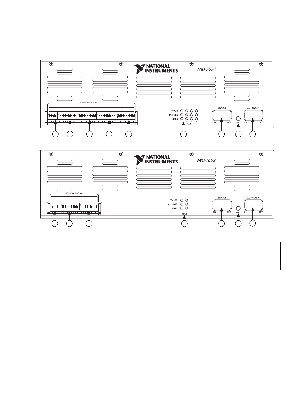
Figure 1 shows the front panel for your MID-7654/7652. The DIP switches
are shown with the detachable metal cover plate removed.
POL AXIS 1 AXIS 2 AXIS 3 AXIS 4
21 3 4 5
MID-7654
4 Axis Servo Motor Drive
4 Axis Servo Motor Drive
6
2 Axis Servo Motor Drive
7
8
9
POL AXIS 1 AXIS 2
21 3
6
7
9
8
MID-7652
1 Polarity DIP Switch Bank
2 Axis 1 DIP Switch Bank
3 Axis 2 DIP Switch Bank
4Axis3DIPSwitchBank*
5Axis4DIPSwitchBank*
6 LED Status Array
7 Enable Switch
8 Green Power LED
9 Power Switch
* This DIP switch bank is only available on the MID-7654.
Figure 1. MID-7654/7652 Front Panel
There are two rocker switches on the MID-7654/7652 front panel:
AC POWER and ENABLE. Figure 1 illustrates the location of these
switches.
The AC POWER switch energizes the motor bus (+48 V) and the logic
(+5 V) power supplies. When switched on, the green power LED labeled
+5 V illuminates. If this LED fails to illuminate, check the power cord and
main input fuse on the back panel.
© National Instruments Corporation 5 MID-7654/7652 Servo Power Motor Drive User Guide
Page 6

The ENABLE switch enables or inhibits the servo amplifiers. If the
ENABLE switch is in the inhibit position (OFF), the amplifier output stages
are inhibited and the yellow LEDs for all axes illuminate. See the Front
Panel LEDs section of this guide for more information.
Both the AC POWER and ENABLE switches can inhibit the servo
amplifiers. However, as long as the AC POWER switch is on, only the servo
amplifier output stages are disabled. The remaining circuitry remains
active, including the quadrature encoder circuit.
Warning
change the line voltage from the factory setting. Refer to the Specifications section of this
guide for fuse specifications. Refer to the Modifying the Power Entry Module section for
moreinformationonhandlingthepowerentrymodule.
Yo u must change the MID-7654/7652 main input fuse on the rear panel if you
Host Bus Interlock Circuit
The MID-7654/7652 has a host bus interlock circuit that monitors the
presence of +5 V from the host computer and disables the MID-7654/7652
when the voltage is not present or falls out of tolerance. This circuit shuts
down the servo amplifiers for all axes by activating the inhibit when the
host computer is disconnected from the MID-7654/7652 or inadvertently
shut down. Activation of the host bus interlock circuitry illuminates the
yellow LEDs (middle row) of the LED status array for all axes. See the
FrontPanelLEDssection of this guide for more information.
Front Panel LEDs
The front panel LEDs consist of a single green LED to indicate if the main
5 V power is active. If the DC power supplies are active, the green power
LED illuminates. If this LED fails to illuminate, check the power cord and
the main input fuse on the front panel.
An LED status array of 3 rows by 4 columns on the MID-7654 or 3 rows
by 2 columns on the MID-7652 provides a variety of status information.
Refer to Figure 1 for the location of the front panel LEDs. The LED status
array is arranged by motor axes. Each of the four columns represents an
axis, and each of the three rows represents a particular status. Table 1
summarizes the axes and statuses to which the different LEDs in the 3 × 4
or 3 × 2 array correspond.
MID-7654/7652 Servo Power Motor Drive User Guide 6 ni.com
Page 7

Amplifier Fault Output (red) 1 2 3
Amplifier Inhibit (yellow) 1 2 3
Limit Status (green) 1 2 3
*
These LEDs only appear on the MID-7654.
Amplifier Fault Output LEDs
The top row of the LED status array indicates the status of the amplifiers.
A red LED indicates an overcurrent condition, a short circuit condition, an
over temperature condition, or a problem with the motor bus voltage on that
axis.
Amplifier Inhibit LEDs
The middle row of the LED status array indicates if a motor axis is
inhibited. An axis is inhibited and the LED illuminates yellow if the host
bus interlock circuitry is activated from the back panel, if the ENABLE
switch on the front panel is in the inhibit position, if the motion controller’s
inhibit signal is low, or if the per-axis inhibit input is actively driven. You
can select the polarity of the per-axis inhibit input from the front panel DIP
switches. See the Front Panel DIP Switch Settings section of this guide for
more information.
Table 1. Front Panel LED Indicators
Status Motor Axis
*
*
*
*
4
*
4
*
4
Limit Status LEDs
The bottom row of the LED status array indicates if a limit switch is
currently active. The LED illuminates green when either the forward or
reverse limit switch is active for each axis. You can select the polarity for
the limit status LEDs from the front panel DIP switches. See the Front
Panel DIP Switch Settings of this guide for more information.
© National Instruments Corporation 7 MID-7654/7652 Servo Power Motor Drive User Guide
Page 8
Front Panel DIP Switch Settings
The MID-7654/7652 front panel has a detachable metal plate that, when
removed, provides access to one 4-position DIP switch bank and either four
(MID-7654) or two (MID-7652) 9-position DIP switch banks. Refer to
Figure 1 for the location of these switches.
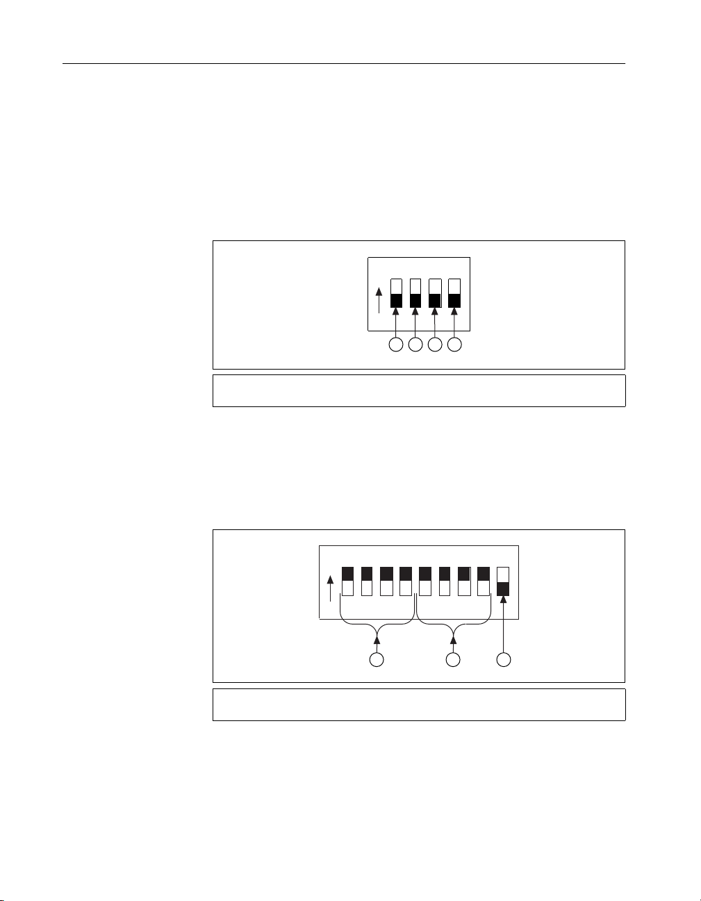
Use the DIP switches on the 4-position DIP switch bank to configure the
inhibit in, inhibit out, and limit status LED polarity as shown in Figure 2.
The different settings for these switches are described in the following
sections.
O
N
1234
1 2 3 4
1 Inhibit In Polarity Switch
2 Inhibit Out Polarity Switch
3 Limit Status LED Polarity Switch
4 Reserved
Figure 2. 4-Position DIP Switch Bank Layout
Use the DIP switches on each 9-position DIP switch bank to configure the
continuous current limit, the peak current limit, and the motor inductance
(low or standard) for each axis, as shown in Figure 3. The different settings
for these switches are described in the following sections.
O
123456789
N
1 2
1 Continuous Current Limit Switches
2 Peak Current Limit Switches
Figure 3. 9-Position DIP Switch Bank Layout
3 Motor Inductance Switch
3
MID-7654/7652 Servo Power Motor Drive User Guide 8 ni.com
Page 9
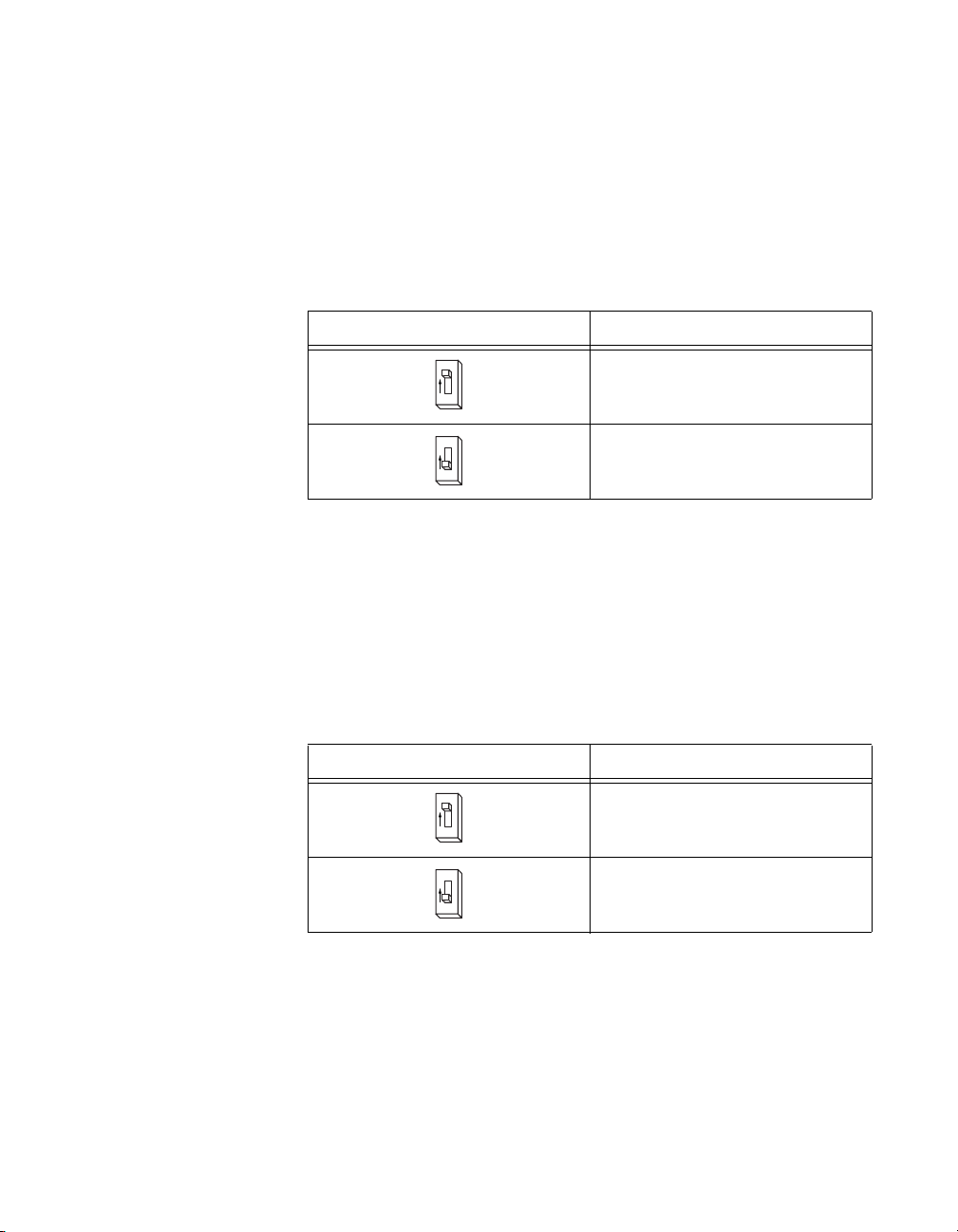
Inhibit Input Polarity Setting
UseDIPswitch1onthe4-positionDIPswitchbanktogloballysetthe
polarity for the inhibit input for all axes. Refer to Figures 1 and 3 for the
location of this switch.
The factory-default setting of DIP switch 1 is active-low. If the inhibit input
is active, the axis is inhibited and the yellow status LED (middle row)
corresponding tothat axis illuminates. Table 2 shows the DIP switch setting
for the inhibit input polarity selection.
Switch Setting Operation
Inhibit Output Polarity Setting
UseDIPswitch2onthe4-positionDIPswitchbanktogloballysetthe
polarity for the inhibit output for all axes. Refer to Figures 1 and 3 for the
location of this switch.
The factory-default setting of DIP switch 2 is active-high. Table 3 shows
the DIP switch setting for the inhibit output polarity selection.
Switch Setting Operation
Table 2.
O
N
1
O
N
1
Table 3.
O
N
3
Inhibit Input Polarity DIP Switch Settings
Active-high
Active-low
(factory default)
Inhibit Output Polarity DIP Switch Settings
Active-high
(factory default)
O
N
3
© National Instruments Corporation 9 MID-7654/7652 Servo Power Motor Drive User Guide
Active-low
Page 10
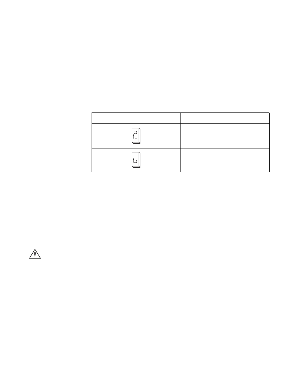
Limit Status LED Polarity Setting
UseDIPswitch3onthe4-positionDIPswitchbanktogloballysetthe
polarity for the Limit Status LED. Refer to Figures 1 and 3 for the location
of this switch.
The factory-default setting is active-high. Typically, you set the switch to
match your controller’s polarity setting, so if either the reverse or forward
limits for an axis are active, the green status LED (on the bottom row)
corresponding to that axis illuminates. This DIP switch alters only the
polarity for the LEDs, not the actual limit to the motion controller. Table 4
shows the DIP switch setting for the Limit Status LED polarity selection.
Table 4. Limit Status LED DIP Switch Settings
Switch Setting Operation
O
N
2
O
N
2
Setting Continuous and Peak Current Limits
The MID-7654/7652 uses high-efficiency PWM amplifiers configured as
torque blocks (current amplifiers or transconductance amplifiers). The
peak current limit is the maximum current your motor can withstand for
short periods of time. The continuous current limit is the maximum current
your motor can withstand indefinitely. The MID-7654/7652 varies the gain
applied to the input voltage so the maximum input voltage corresponds to
a current output equal to the peak current limit, I
Caution
error trip point is set above zero in the motion controller configuration software. The
default following error is 32,767.
To avoid overheating the drive under a motor fault condition, ensure the following
Active-high
(factory default)
Active-low
.
peak
MID-7654/7652 Servo Power Motor Drive User Guide 10 ni.com
Page 11
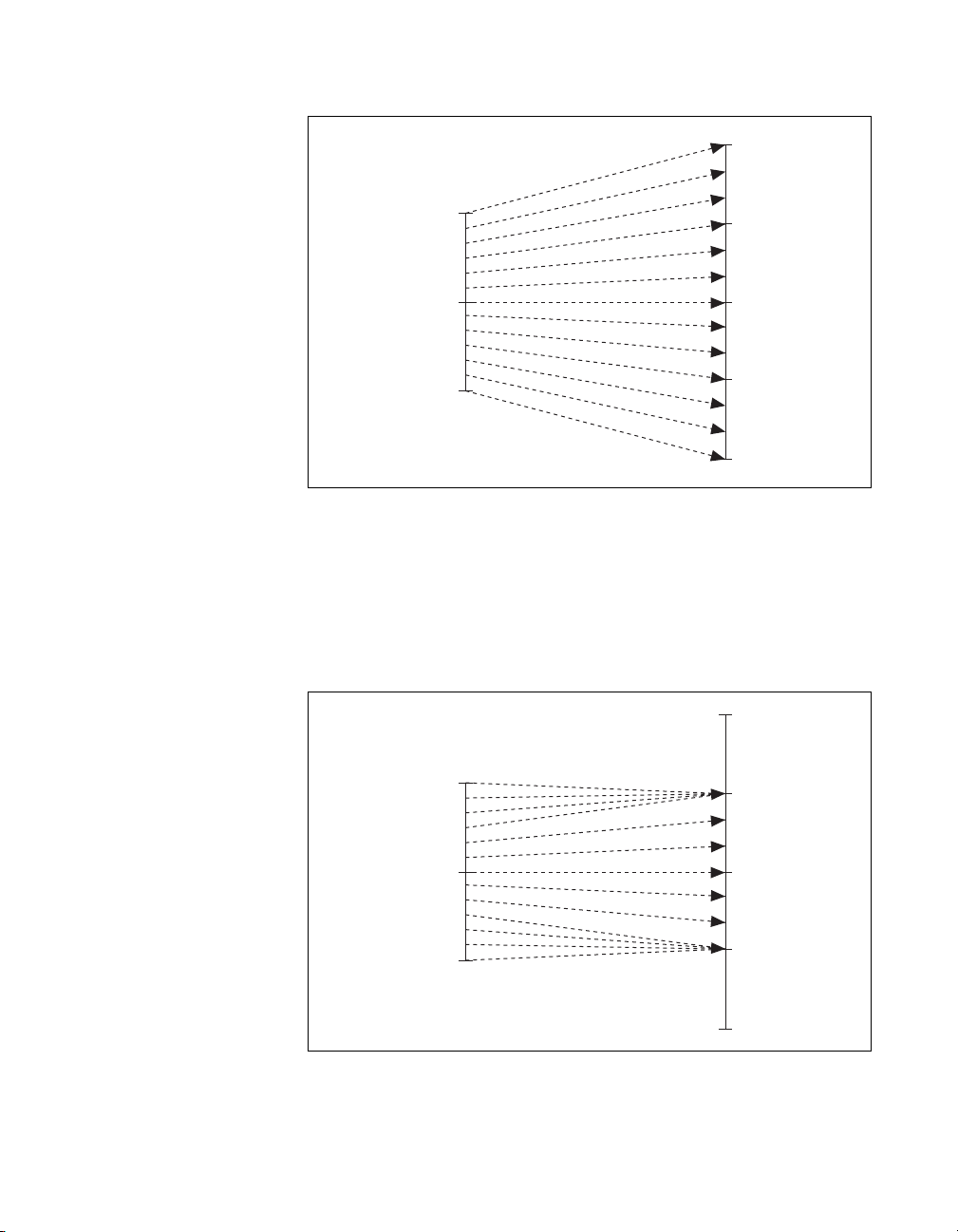
Figure 4 illustrates the command voltage input to current output
relationship for periods of time less than 2.7 seconds.
+I
peak
+V
max
+I
cont
0V
0A
Output Current
–I
Input Command Voltage
–V
max
Gain Applied
cont
–I
peak
Figure 4. Input Voltage to Output Current Relationship for Periods
of Time Less Than 2.7 Seconds
Figure 5 shows the command voltage input to current output relationship
for periods of time greater than 2.7 seconds. The maximum current output
corresponds to the continuous current limit, I
voltages that would result in a higher current output than I
is applied instead result in a current output of I
+V
max
. Therefore, command
cont
cont
.
when the gain
cont
+I
peak
+I
cont
0V
0A
Output Current
–I
Input Command Voltage
–V
max
Gain Applied
cont
–I
peak
Figure 5. Input Voltage to Output Current Relationship for Periods
of Time Greater Than 2.7 Seconds
© National Instruments Corporation 11 MID-7654/7652 Servo Power Motor Drive User Guide
Page 12

The amplifier peak and continuous current limits have been factory set for
5 A continuous current output and 10 A peak current output. Verify that
these settings are appropriate for your application before powering your
motors.
Use DIP switches 1 through 4 on each of the 9-position DIP switch banks
to set the continuous current limit for each axis. Use DIP switches
5 through 8 on each of the 9-position DIP switch banks to set the peak
current limit for each axis. Refer to Figures 1 and 3 for the location of the
continuous current limit and peak current limit switches. Table 5 shows the
DIP switch settings for all possible current limit settings.
Note
The switches shown in Table 5 show the settings for switches 1 through 4, which are
the continuous current DIP switches. Configure the settings for switches 5 through 8 in the
same manner to set the peak current values.
Table 5. Continuous and Peak Output Current DIP Switch Settings
Continuous
Switch
O
N
1
234
O
N
1
234
O
N
1
234 1
O
N
1
234 1
O
N
1
234
O
N
1
234 1
O
N
1
234
O
N
1
234
Current (A)
5.00 10.00 1.25 2.50
4.50 9.00 1.15 2.30
3.80 7.55 1.10 2.20
3.00 6.00 1.05 2.10
2.45 4.90 1.00 1.95
2.10 4.20 0.95 1.85
1.95 3.85 0.90 1.80
1.70 3.45 0.85
Peak Current
(A)
Switch
O
N
1
234
O
N
1
234
O
N
234
O
N
234
O
N
1
234
O
N
234
O
N
1
234
O
N
1
234
Continuous
Current (A)
(default)
Peak Current
(A)
1.70
(default)
MID-7654/7652 Servo Power Motor Drive User Guide 12 ni.com
Page 13

If you are connecting multiple motors to your MID-7654/7652, verify that
the total power dissipated by the motors at any given time is less than the
total power the drive can provide. If the total power requirement exceeds
the capability of the drive at any point, the drive will provide less power to
the motors than desired until the total power requirement drops back down.
Your MID-7654/7652 may overheat under continuous operation with loads
that exceed specified limits.
Caution
400 W at 25% duty cycle for a sustained period of time.
A fire safety hazard exists when the total power dissipated by the motors exceeds
To determine the maximum total power dissipation of all of the motors
combined, add up the maximum power each motor can dissipate. If this
value is less than or equal to 400 W at 25% duty cycle, you will not exceed
the capabilities of the MID-7654/7652.
If the value is greater than 400 W at 25% duty cycle, you may still be within
the operating capabilities of the MID-7654/7652, since it is unlikely you
will run all of your motors simultaneously at their maximum levels. Make
a reasonable estimation of the maximum power your motors will require at
any given time and verify that this value is less than 400 W at 25% duty
cycle.
Setting Motor Inductance Levels
Depending on the construction of your motor, you may need to configure
one or more axes to the low inductance setting rather than the default
standard inductance setting. Table 6 shows the motor inductance level
ranges for the two different settings.
Motor Inductance MID-7654/7652 Setting
Table 6. Motor Inductance Levels
Greater than 440 µH Standard
Between 110 and 440 µH Low
© National Instruments Corporation 13 MID-7654/7652 Servo Power Motor Drive User Guide
Page 14

Use the last DIP switch on each of the 9-position DIP switch banks to set
the motor inductance level for each axis. Refer to Figures 1 and 3 for the
location of the of the motor inductance level switch. Table 7 shows the DIP
switch settings for low and standard motor inductance.
Table 7. Motor Inductance Level DIP Switch Settings
Switch Setting Operation
O
N
9
O
N
9
Low motor inductance
Standard motor inductance
(factory default)
MID-7654/7652 Servo Power Motor Drive User Guide 14 ni.com
Page 15

Back Panel Connector Wiring
Figure 6 shows the MID-7654/7652 back panel connectors without their
rear guards.
MID-7654
MID-7652
1 Motion Controller Connector
2 Analog Input Connector
3 Analog Output Connector
4 Trigger Connector
5 Breakpoint Connector
6 Step/Direction Connector
7ACPower
* This connector is available only on the MID-7654.
Encoder
Connectors
8Axis1
9Axis2
10 Axis 3*
11 Axis 4*
Limit
Connectors
12 Axis 1
13 Axis 2
14 Axis 3*
15 Axis 4*
Motor
Connectors
16 Axis 1
17 Axis 2
18 Axis 3*
19 Axis 4*
Figure 6. MID-7654/7652 Back Panel Connectors
© National Instruments Corporation 15 MID-7654/7652 Servo Power Motor Drive User Guide
Page 16

Caution
Be sure to turn off the ENABLE and AC POWER switches for your
MID-7654/7652 and host computer and disconnect the unit from the power outlet before
making connections to your motion controller.
Warning
The servo motor connectors on this drive are energized when the unit is powered
on. The rear guard must be in place at all times while the unit is connected to a power
outlet. Disconnect the MID-7654/7652 unit from power outlet before connecting wires
to or disconnecting wires from the servo motor connectors. Strip back the insulation of
the servo motor wires to the servo motor connectors no more than 7 mm. Reattach the rear
guard before you reconnect the unit to a power outlet. Failure to do so could result in
electric shock leading to serious bodily injury or death. Refer to the Rear Guard section of
this guide for information on using the rear guard.
Take the following steps to wire your motion system to your
MID-7654/7652:
1. Connect the motion controller to the MID-7654/7652 using the
interface cable. Wire the motor power, limit switch, encoder, and I/O
terminal blocks to your motion control system.
2. For proper operation, configure the power entry module to match the
voltage of your power source. Refer to the Modifying the Power Entry
Module section for more information.
Caution
Yo u must change the MID-7654/7652 main input fuse on the rear panel if you
change the line voltage from the factory setting. Refer to the Replacing a Fuse section in
the Modifying the Power Entry Module section of this guide for information on changing
afuse.
3. Install the power cord into the back panel AC connector and plug it into
a correctly rated power source.
MID-7654/7652 Servo Power Motor Drive User Guide 16 ni.com
Page 17

Terminal Block Wiring
This section describes how to wire the terminal blocks on your
MID-7654/7652.
Servo Motor Power Terminal Blocks
For motor power wiring, each MID-7654/7652 axis has a separate
5-position removable screw terminal block. Figure 7 shows a typical servo
motor configuration pin assignment. The dotted loop indicates a shielded
cable.
Warning
Motor +
Motor –
Shield
Figure 7.
+ –
Servo Motor
Typical Servo Motor (DC Brush Type) Terminal Block Pin Assignment
Motor Case Ground
The servo motor connectors on this drive are energized when the unit is powered
1
2
3
4
5
on. The rear guard must be in place at all times while the unit is connected to a power
outlet. Disconnect the MID-7654/7652 unit from power outlet before connecting wires
to or disconnecting wires from the servo motor connectors. Strip back the insulation of
the servo motor wires to the servo motor connectors no more than 7 mm. Reattach the rear
guard before you reconnect the unit to a power outlet. Failure to do so could result in
electric shock leading to serious bodily injury or death. Refer to the Rear Guard section of
this guide for information on using the rear guard.
You should use shielded 20 AWG wire or larger for the motor power
cable. If available, connect a motor case ground wire to pin 3
(Ground/Shield) on the MID-7654/7652 as shown in Figure 7; this wire
helps avoid ground loops and signal noise problems. (Case ground connects
to the motor housing, not to any of the motor power terminals.)
Caution
© National Instruments Corporation 17 MID-7654/7652 Servo Power Motor Drive User Guide
Never connect unused center taps or winding terminals to pin 3.
Page 18

Depending on your motor, you may need to reverse the connections shown
in Figure 7, as there is no industry standard for direction of movement
relative to the positive and negative motor inputs. Table 8 shows the
National Instruments motion control standard directional polarity.
Table 8. National Instruments Standard Directional Polarity
Commanded
Direction
Description
Forward Clockwise (CW) facing
motor shaft
Reverse Counter-clockwise (CCW)
facing motor shaft
Figure 8 shows clockwise and counter-clockwise motor rotation.
Figure 8. Clockwise and Counter-Clockwise Motor Rotation
Motor Signal
Relationship
Motor – is greater than
Motor +
Motor + is greater than
Motor –
CCW
Command
Signal
Positive voltage
Negative voltage
CW
MID-7654/7652 Servo Power Motor Drive User Guide 18 ni.com
Page 19

Rear Guard
The rear guard consists of the protection cover, protection plates, and
bottom mounting plate as shown in Figure 9.
1 Bottom Mounting Plate
2ProtectionCover
Figure 9. Rear Guard Consisting of the Protection Cover,
Protection Plates, and Bottom Mounting Plate
3ProtectionPlate
© National Instruments Corporation 19 MID-7654/7652 Servo Power Motor Drive User Guide
Page 20

The rear guard installed on the MID-7654/7652 is shown in Figure 10.
INSTRUMENTS
NATIONAL
Figure 10. Rear Guard Installed on the MID-7654/7652
Warning
The servo motor connectors on this drive are energized when the unit is powered
on. The rear guard must be in place at all times while the unit is connected to a power
outlet. Disconnect the MID-7654/7652 unit from power outlet before connecting wires
to or disconnecting wires from the servo motor connectors. Strip back the insulation of
the servo motor wires to the servo motor connectors no more than 7 mm. Reattach the rear
guard before you reconnect the unit to a power outlet. Failure to do so could result in
electric shock leading to serious bodily injury or death.
Follow these steps carefully to ensure safe operation of your
MID-7654/7652:
1. Ensure that the MID-7654/7652 is powered off and disconnected from
the power outlet before wiring any cables to the unit. The +5V green
LED should not be illuminated after the MID-7654/7652 is powered
off and disconnected from the power outlet.
2. Ensure that the bottom mounting plate of the rear guard is securely
fastened to both sides of the MID-7654/7652, as shown in Figure 10.
3. Remove the protection plates for the axes to be used, rotate, and
re-install the protection plates in the open position, as shown in
Figure 11.
MID-7654/7652 Servo Power Motor Drive User Guide 20 ni.com
Page 21

1ProtectionCover 2ProtectionPlate
Figure 11. Protection Cover and Protection Plates:
Used Axes 1 & 2, Unused Axes 3 & 4.
Note
The protection plates for any unused axes should remain installed in the closed
position at all times, as shown on axes 3 and 4 in Figure 11. For axes you are using, the
protection plates must be removed, rotated, and re-installed in the open position, as shown
onaxes1and2inFigure11.
Contact your National Instruments sales representative to replace lost protection plates
(part number 188063A-01).
4. Remove the protection cover using the following procedure:
a. Remove the two screws that attach the protection cover to the side
of the bottom mounting plate, as shown in Figure 10.
b. Lift the protection cover from the slot on the bottom mounting
plate, as shown in Figure 9.
5. Plug the servo motor cables into the servo motor terminals of the
MID-7654/7652. The cables must be placed over the bottom mounting
plate of the rear guard.
6. Re-attach the protection cover
a. Insert the tab of the protection cover, shown in Figure 9, into the
slot on the bottom mounting plate.
b. Lower the protection cover over the servo motor cables and secure
it to the side of the bottom mounting plate using the two screws
youremovedinstep4.
© National Instruments Corporation 21 MID-7654/7652 Servo Power Motor Drive User Guide
Page 22

7. Ensure that the rear guard is held securely in place before reconnecting
your MID-7654/7652 to a power outlet.
Encoder Terminal Blocks
For quadrature incremental encoder signals, each MID-7654/7652 axis has
a separate 8-position removable screw terminal block. Where applicable,
the MID-7654/7652 accepts two types of encoder signal inputs:
single-ended (TTL) or differential line driver. You can accommodate
open-collector output encoders by using 2.2 kΩ pullup resistors to
+5 VDC.
Figure 12 shows the typical encoder wiring pin assignment for
single-ended signal input.
Encoder A
Encoder B
Encoder Index
+5 V
Digital Ground
1
2
3
4
5
6
7
8
Figure 12. Typical Single-Ended Encoder Wiring Pin Assignment
Figure 13 shows the typical encoder wiring pin assignment for differential
line driver signal inputs.
Encoder A
Encoder A
Encoder B
Encoder B
Encoder Index
Encoder Index
+5 V
Digital Ground
Figure 13. Typical Differential Line Driver Encoder Wiring Pin Assignment
1
2
3
4
5
6
7
8
If the encoder cable length is greater than 10 ft, use encoders with line
driver outputs for your applications. Power for a +5 V encoder—generated
by a power supply inside the MID-7654/7652—is available on pin 7.
MID-7654/7652 Servo Power Motor Drive User Guide 22 ni.com
Page 23

Note
If you require other encoder power voltages, reference an external power supply to
the Digital Ground signal on the 8-pin encoder terminal block.
The MID-7654/7652 supports differential inputs for Phase A, Phase B, and
Index signals. You can easily accommodate encoders with various phase
relationships by swapping the signals and/or connecting them to the
inverting inputs as required by your application. The Index signal must
occur when both Phase A and Phase B signals are low, as shown in
Figure 14. If the Index polarity is inverted, try reversing the Index and
Index
signals on differential encoders or using the Index input on
single-ended encoders.
Figure 14 shows the proper encoder phasing for CW (forward) motor
rotation.
Phase A
Phase B
Index
Figure 14. Encoder Signal Phasing, CW Rotation
Closed-loop servo applications require consistent directional polarity
between the motor and encoder for correct operation. The National
Instruments motion control standard directional polarity is as follows:
• Positive = forward = clockwise (CW) facing motor shaft
• Negative = reverse = counter-clockwise (CCW) facing motor shaft
Refer to Figure 8 for a depiction of clockwise and counter-clockwise
rotation.
When connecting the encoder wiring to your MID-7654/7652, use shielded
wire of at least 24 AWG. You must use cables with twisted pairs and an
overall shield for improved noise immunity and enhanced encoder signal
integrity. Figure 15 shows twisted pairs in a shielded cable.
© National Instruments Corporation 23 MID-7654/7652 Servo Power Motor Drive User Guide
Page 24

Shield
Drain
Encoder A
Encoder A
Encoder B
Encoder B
Encoder Index
Encoder Index
+5 V
Digital
Ground
Figure 15. Shielded Twisted Pairs
Note
Using an unshielded cable may produce noise, which can corrupt the encoder signals
and cause lost counts, reduced accuracy, or other erroneous encoder and controller
operation.
Limit Switch Terminal Blocks
For end-of-travel limit, home, inhibit input, and inhibit output connections,
MID-7654/7652 axes have a separate, 6-position removable screw terminal
connector block. Figure 16 shows the limit switch terminal block pin
assignments.
Forward Limit
Home Input
Reverse Limit
Inhibit Input
Inhibit Output
Digital Ground
1
2
3
4
5
6
Figure 16. Limit Switch Terminal Block Pin Assignment
(Passive Limit Switch Connection Example)
You can configure the inhibit output signal to be asserted low or asserted
high from the MID-7654/7652 when an axis is inhibited. This signal can be
useful for actuating mechanical brakes or for monitoring an axis status.
Refer to the Amplifier Inhibit LEDs section of this guide for a description
of the conditions that will cause an axis to be inhibited.
MID-7654/7652 Servo Power Motor Drive User Guide 24 ni.com
Page 25

Breakpoint and Trigger Terminal Blocks
Both the breakpoint and trigger connectors use a 6-pin removable terminal
block.
The trigger terminal block provides access to the trigger input lines,
shutdown input line, and digital ground. The breakpoint terminal block
provides access to the breakpoint output lines, the +5 V supplied by the
MID-7654/7652, and the digital ground. Figures 17 and 18 show the
breakpoint and trigger 6-position terminal block assignments.
Trigger Input 1
Trigger Input 2
Trigger Input 3
Trigger Input 4
Shutdown Input
Digital Ground
Figure 17. Trigger Terminal Block Pin Assignment
Breakpoint Output 1
Breakpoint Output 2
Breakpoint Output 3
Breakpoint Output 4
+5 V
Digital Ground
Figure 18. Breakpoint Terminal Block Pin Assignment
1
2
3
4
5
6
1
2
3
4
5
6
Analog I/O Terminal Blocks
The MID-7654/7652 features two analog I/O connectors.
The analog input connector uses a 6-pin removable terminal block, which
provides access to four analog-to-digital converter channels, an analog
reference voltage from the converter circuit, and an analog input ground
signal.
The analog output connector uses a 5-pin removable terminal block, which
provides access to four digital-to-analog converter channels and analog
output ground. Refer to Figures 19 and 20 for terminal block pin
assignments.
© National Instruments Corporation 25 MID-7654/7652 Servo Power Motor Drive User Guide
Page 26

Analog Input 1
Analog Input 2
Analog Input 3
Analog Input 4
Analog Reference (Output)
Analog Input Ground
1
2
3
4
5
6
Figure 19. Analog Input Terminal Block Pin Assignment
Analog Output 1
Analog Output 2
Analog Output 3
Analog Output 4
Analog Output Ground
1
2
3
4
5
Figure 20. Analog Output Terminal Block Pin Assignment
Step and Direction Terminal Block
The MID-7654/7652 passes step and direction signals from the controller
directly through the drive, allowing you to access them through the 8-pin
removable terminal block. This feature is useful if your system includes
both stepper and servo motors, as it reduces the amount of custom cabling
required to connect your motors and drives to the controller.
To use the step and direction connector, select an unused axis on the
MID-7654/7652 and connect the step and direction outputs for that axis
to your stepper drive. Refer to Figure 21 for the terminal block pin
assignments. Connect additional signals for the axis, such as inhibit
outputs, limit switches, breakpoints and triggers, and encoder feedback,
as described earlier in this guide.
Step 1
Direction 1
Step 2
Direction 2
Step 3
Direction 3
Step 4
Direction 4
1
2
3
4
5
6
7
8
Figure 21. Step and Direction Terminal Block Pin Assignment
MID-7654/7652 Servo Power Motor Drive User Guide 26 ni.com
Page 27
Cable Installation for CE Compliance
Take the following additional steps to ensure CE Compliance:
1. Enclose the terminal block wires in a 360-degree shielded cable. This
requires a braided shield.
2. Install the strain-relief bar on the MID-7654/7652 as described in the
Accessories Included for Optional Use section of this guide.
3. Place all cables connecting to the back panel through the strain-relief
bar, as follows:
a. All servo motor cables must pass through the far right clamp on
the strain-relief bar, which is directly aligned with the servo motor
terminals and protection cover.
b. All remaining cables should pass through the three clamps to the
left of the servo motor terminals.
c. Cables passing through the same clamp must be of the same cable
diameter.
d. Cables passing through the same clamp must be parallel and must
not overlap each other, as shown in Figure 22.
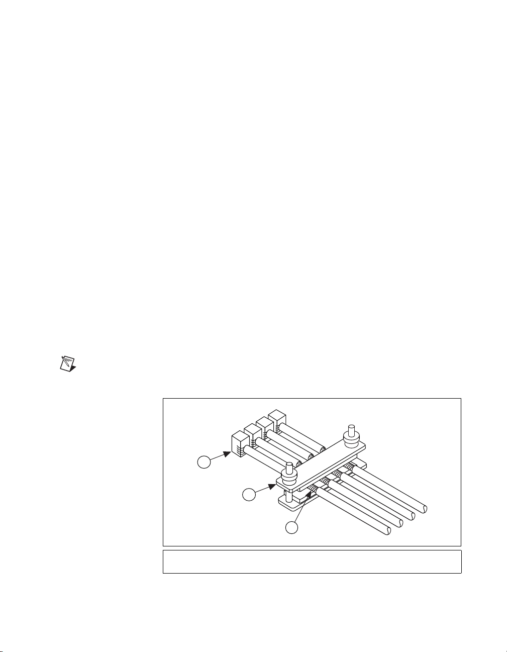
4. All cables must be properly grounded to the strain-relief bar, which
grounds them to the MID-7654/7652 chassis ground. Follow these
steps to ground the cables to the strain-relief bar:
a. Remove the outer jacket from the section of the cable to be
inserted between the strain-relief bar clamp and foam, as shown in
Figure 22. This will expose the braided shield of the cable.
Note
Do not cut the braided shield of the cable.
3
2
1
1 Braided Shield of the Cable
2 Strain Relief Bar
Figure 22. Required Cabling for CE Compliance
© National Instruments Corporation 27 MID-7654/7652 Servo Power Motor Drive User Guide
3 Terminal Block Connector
Page 28

b. Lay the cables so that the braided shield makes full contact with
the foam of the strain-relief bar. The braided shield must only
make contact with the strain-relief bar, and no other part of the
device.
c. Lower the clamp and tighten the thumb nuts to remove all gaps
between the foam and the cable shields. The foam should press
around the shield of the cable to provide 360-degree grounding to
the cable shield.
5. Ground the braided shield at the opposite end of the cables to your
destination enclosure ground.
Accessories Included for Optional Use
Strain-Relief Bar Installation
The strain-relief bar provides strain relief for wiring to the back panel
terminals of the MID-7654/7652. It must be used to provide necessary
grounding for CE compliance. Refer to the Cable Installation for CE
Compliance section of this guide for more information.
The arms of the strain-relief bar attach between the sides of the
MID-7654/7652 and the bottom mounting plate of the rear guard with the
thumb nuts facing upwards, as shown in Figure 23. Refer to the Rear Guard
section of this guide for more information on removing and replacing the
protection cover from the rear guard. Refer to Figure 23 while following
these strain-relief bar installation steps:
1. Remove the protection cover of the rear guard.
2. Place the strain-relief bar so it fits within the sides of the bottom
mounting plate.
3. Attach the strain-relief bar to the side panels of the MID-7654/7652
using the provided screws.
4. Replace the protection cover.
MID-7654/7652 Servo Power Motor Drive User Guide 28 ni.com
Page 29

1
1 Rear Guard Assembly 2 Strain Relief Bar
Figure 23. MID-7654/7652 with the Strain-Relief Bar Installed
Panel Mount Kit Installation
The panel mount kit allows you to mount the MID-7654/7652 inside a
cabinet or enclosure. Attach the panel mount kit to the rear and front set
of screw holes on the side panels of the MID-7654/7652, as shown in
Figure 24, using the provided screws.
2
© National Instruments Corporation 29 MID-7654/7652 Servo Power Motor Drive User Guide
Page 30

INSTRUMENTS
NATIONAL
1
1 Rear Guard Assembly 2 Panel Mount
Figure 24. MID-7654/7652 with the Panel Mount Kit Installed
Note
The strain-relief bar and panel mount kit cannot be installed at the same time,
because they will not simultaneously fit under the sides of the bottom mounting plate.
Modifying the Power Entry Module
This section covers replacing fuses and switching the line voltage for
your drive.
Replacing a Fuse
Follow these steps to replace a fuse on your MID-7654/7652:
1. Pry open the hinged cover on the power entry module (number 7 in
Figure 6).
2. Remove the fuse holder. Notice how the fuse holder is oriented so you
can replace it properly.
3. Replace the blown fuse in the fuse holder. Be sure the new fuse is
oriented in the same way as the original fuse, and that it is rated at the
proper voltage.
2
MID-7654/7652 Servo Power Motor Drive User Guide 30 ni.com
Page 31

4. Push the fuse holder back into the power entry module with the same
orientation you observed in step 2.
5. Close the hinged cover.
Changing the Line Voltage
Follow these steps to change the line voltage on your MID-7654/7652:
1. Pry open the hinged cover on the power entry module (number 7 in
Figure 6).
2. Remove the fuse holder.
3. Replace the two fuses with the appropriate fuses for the desired line
voltage as listed in the Specifications section.
4. Rotate the fuse holder 180 degrees so the desired line voltage number
shows through the window when the power module cover is closed.
5. Push the fuse holder back into the power entry module with the new
orientation.
6. Close the hinged cover.
Amplifier/Driver Command Signals
The PWM amplifiers used in the MID-7654/7652 accept an
industry-standard ±10 V analog torque (current) command signal. Servo
motion controllers used with the MID-7654/7652 provide this standard
output and are programmed to close both the velocity loop and position
loop using an enhanced PID algorithm.
Specifications
The following specifications apply only to the MID-7654/7652. You must
account for your motion controller to obtain a system specification. Refer
to your controller specifications to determine overall system specifications.
Some signals define compatibility as signal pass-through, which means the
MID-7654/7652 may use passive filtering on these signals. This will not
affect the voltage range or current handling capability. Consult your motion
controller specifications to determine the allowable voltage range and logic
level compatibility of the signal.
Servo Amplifiers
Type ....................................................... Elmo Motion Control VIO 10/100
Peak current limit (2.7 s)........................ 1.7–10 A (default 1.7 A)
© National Instruments Corporation 31 MID-7654/7652 Servo Power Motor Drive User Guide
Page 32

Continuous current limit.........................0.85–5 A (default 0.85 A)
DC-bus motor voltage ............................48 VDC
PWM frequency......................................32 kHz
Continuous power output rating
(all axes combined).................................400 W at 25% duty cycle
Encoders
Inputs ......................................................Quadrature, incremental
Differential input threshold ....................± 0.3 V (typical)
Single ended input threshold ..................TTL/CMOS
Voltage range..........................................0–5VDC
Maximum quadrature frequency.............20 MHz
Limit and Home Switch Inputs
Compatibility ..........................................Signal pass-through
Inhibit Inputs
Voltage range..........................................0–12 VDC
Input low voltage ....................................0.8 V
Input high voltage...................................2 V
Inhibit Outputs
Voltage range..........................................0–5VDC
Output low voltage .................................0.5 V at 64 mA
Output high voltage ................................2.4 V at 32 mA
Trigger Input
Noise filter (RC time constant)...............100 ns
Compatibility ..........................................Signal pass-through
Breakpoint Outputs
Compatibility ..........................................Signal pass-through
MID-7654/7652 Servo Power Motor Drive User Guide 32 ni.com
Page 33

Analog Inputs
Noise filter (RC time constant) .............. 10 µs
Compatibility ......................................... Signal pass-through
Analog Outputs
Compatibility ......................................... Signal pass-through
Step/Direction Outputs
Compatibility ......................................... Signal pass-through
Shutdown Input
Compatibility ......................................... Signal pass-through
User 5 V Supply
Voltage range @ 0.5 A...........................4.7–5.2 V
Included Connectors
Encoders................................................. 8-position mini-combicon
3.81 mm plug (1 per axis)
Limits ..................................................... 6-position mini-combicon
3.81 mm plug (1 per axis)
Servo Motors.......................................... 5-position combicon
5.08 mm plug (1 per axis)
Breakpoints ............................................ 6-position mini-combicon
3.81 mm plug (1 total)
Triggers .................................................. 6-position mini-combicon
3.81 mm plug (1 total)
Step/Direction ........................................ 8-position mini-combicon
3.81 mm plug (1 total)
Analog input........................................... 6-position mini-combicon
3.81 mm plug (1 total)
Analog output......................................... 5-position mini-combicon
3.81 mm plug (1 total)
© National Instruments Corporation 33 MID-7654/7652 Servo Power Motor Drive User Guide
Page 34

Environment
Power Supply
AC power................................................Detachable AC power cord
(IEC standard type)
Motion I/O ..............................................68-pin female high density
VHDCI type
Operating temperature ............................0 to 50 °C (32 to 122 °F)
Storage temperature................................–20 to 70 °C(–4to158°F)
Humidity.................................................10% – 90% (noncondensing)
Maximum Altitude .................................2,000 meters
Pollution Degree .....................................2
Indoor Use Only
Input voltage ...........................................90–132 VAC / 198–264 VAC,
47–63 Hz
Input fuse
115 VAC (factory default)...............8 A (Littelfuse #312008)
230 VAC..........................................6 A (Littelfuse #312006)
Input fuse dimensions.............................0.25 in. by 1.25 in.
Input Power Peak Current (at max load)
115 VAC..........................................10 A
230 VAC..........................................5 A
Installation category ...............................II
Host Bus Voltage Interlock
Undervoltage threshold...........................4 VDC
Physical
Length.....................................................30.6 by 25.4 by 8.8 cm
(12.0by10by3.5in.)
Weight ....................................................10.2 kg (22.5 lb.)
MID-7654/7652 Servo Power Motor Drive User Guide 34 ni.com
Page 35

Safety
Meets the requirements of the following standards for safety for electrical
equipment for measurement, control, and laboratory use:
• EN 61010-1:1993/A2:1995, IEC 61010-1:1990/A2:1995
• UL 3101-1:1993, UL 3111-1:1994, UL 3121-1:1998
• CAN/CSA C22.2 No. 1010.1:1992/A2:1997
UL Recognized to UL 508C, power conversion equipment, File # E208822
Electromagnetic Compatibility
EMC/EMI............................................... CE, C-Tick and FCC Part 15
Electrical emissions................................ EN 55011 Class A @ 10 meters
Electrical immunity................................ Evaluated to EN 61326:1998,
Note
This device should only be operated with shielded cabling for full EMC & EMI
compliance. Refer to the Declaration of Conformity (DoC) for this product for any
additional regulatory compliance information. The DoC for this product is available via the
following web site:
by product family. Select the appropriate product family, followed by your product and a
link to the DoC will appear in Adobe Acrobat format. Click on the Acrobat icon to
download or read the DoC.
http://digital.ni.com/hardref.nsf
(Class A) Compliant.
FCC Part 15A above 1 GHz.
Table 1
. This site lists the DoCs
© National Instruments Corporation 35 MID-7654/7652 Servo Power Motor Drive User Guide
Page 36

Technical Support Resources
NI Web Support
National Instruments Web support is your first stop for help in solving
installation, configuration, and application problems and questions.
Online problem-solving and diagnostic resources include frequently
asked questions, knowledge bases, product-specific troubleshooting
wizards, manuals, drivers, software updates, and more. Web support is
available through the Technical Support section of
Worldwide Support
National Instruments has offices located around the world to help address
your support needs. You can access our branch office Web sites from the
Worldwide Offices section of
up-to-date contact information, support phone numbers, e-mail addresses,
and current events.
If you have searched the technical support resources on our Web site
and still cannot find the answers you need, contact your local office or
National Instruments corporate. For telephone support in the United States,
dial 512 795 8248. For telephone support outside the United States, contact
your local branch office:
Australia 03 9879 5166, Austria 0662 45 79 90 0, Belgium 02 757 00 20,
Brazil 011 284 5011, Canada (Calgary) 403 274 9391,
Canada (Montreal) 514 288 5722, Canada (Ottawa) 613 233 5949,
Canada (Québec) 514 694 8521, Canada (Toronto) 905 785 0085,
China (Shanghai) 021 6555 7838, China (ShenZhen) 0755 3904939,
Denmark 45 76 26 00, Finland 09 725 725 11, France 01 48 14 24 24,
Germany 089 741 31 30, Greece 30 1 42 96 427, Hong Kong 2645 3186,
India 91805275406, Israel 03 6120092, Italy 02 413091,
Japan 03 5472 2970, Korea 02 596 7456, Malaysia 603 9596711,
Mexico 5 280 7625, Netherlands 0348 433466,
New Zealand 09 914 0488, Norway 32 27 73 00, Poland 0 22 528 94 06,
Portugal 351 1 726 9011, Singapore 2265886, Spain 91 640 0085,
Sweden 08 587 895 00, Switzerland 056 200 51 51,
Taiwan 02 2528 7227, United Kingdom 01635 523545
ni.com
ni.com
. Branch office Web sites provide
.
 Loading...