

Page 1

National Instruments MID-7654 Manual
Get Pricing & Availability at
ApexWaves.com
Call Today: 1-800-915-6216
Email: sales@apexwaves.com
https://www.apexwaves.com/modular-systems/national-instruments/motor-drives/MID-7654
Page 2

SER GUIDE
MID-7654/7652 Servo Power Motor Drive User Guide and Specifications
This user guide describes the electrical and mechanical aspects of the MID-7654/7652 servo power
motor drive and describes how to use the MID-7654/7652 with your motion controller.
Contents
Conventions ......................................................................................................................................... 2
Introduction.......................................................................................................................................... 2
What You Need to Get Started ............................................................................................................ 3
Safety Information ............................................................................................................................... 3
Electromagnetic Compatibility Information........................................................................................ 5
Front Panel Switches ........................................................................................................................... 6
Host Bus Interlock Circuit ................................................................................................................... 7
Front Panel LEDs................................................................................................................................. 7
Amplifier Fault Output LEDs ...................................................................................................... 7
Amplifier Inhibit LEDs................................................................................................................ 7
Limit Status LEDs ....................................................................................................................... 8
Front Panel DIP Switch Settings ......................................................................................................... 8
Inhibit Input Polarity Setting ....................................................................................................... 9
Inhibit Output Polarity Setting..................................................................................................... 9
Limit Status LED Polarity Setting ...............................................................................................9
Setting Continuous and Peak Current Limits .............................................................................. 10
Setting Motor Inductance Levels .................................................................................................13
Back Panel Connector Wiring ............................................................................................................. 14
Terminal Block Wiring ................................................................................................................ 15
Servo Motor Power Terminal Blocks .................................................................................. 15
Rear Guard ........................................................................................................................... 16
Encoder Terminal Blocks .................................................................................................... 19
Limit Switch Terminal Blocks............................................................................................. 21
Breakpoint and Trigger Terminal Blocks ............................................................................ 21
Analog I/O Terminal Blocks................................................................................................ 22
Step and Direction Terminal Block ..................................................................................... 22
Cable Installation for CE Compliance ......................................................................................... 23
Accessories Included for Optional Use ............................................................................................... 24
Strain-Relief Bar Installation ....................................................................................................... 24
Panel Mount Kit Installation........................................................................................................ 25
Modifying the Power Entry Module.................................................................................................... 25
Replacing a Fuse.......................................................................................................................... 25
Changing the Line Voltage .......................................................................................................... 26
Amplifier/Driver Command Signals.................................................................................................... 26
Specifications....................................................................................................................................... 26
Where to Go for Support ..................................................................................................................... 30
Page 3
Conventions
The following conventions are used in this guide:
» The » symbol leads you through nested menu items and dialog box options to a final action.
The sequence Options»Settings»General directs you to pull down the Options menu, select
the Settings item, and select General from the last dialog box.
This icon denotes a note, which alerts you to important information.
This icon denotes a caution, which advises you of precautions to take to avoid injury, data loss,
or a system crash. When this symbol is marked on a product, refer to the Specifications section
of this guide for information about precautions to take.
When this symbol is marked on a product, it denotes a component that may be hot.
Touching this component may result in bodily injury.
bold Bold text denotes items that you must select or click in the software, such as menu items and
dialog box options. Bold text also denotes parameter names.
italic Italic text denotes variables, emphasis, a cross-reference, or an introduction to a key concept.
Italic text also denotes text that is a placeholder for a word or value that you must supply.
monospace Text in this font denotes text or characters that you should enter from the keyboard, sections
of code, programming examples, and syntax examples. This font is also used for the proper
names of disk drives, paths, directories, programs, subprograms, subroutines, device names,
functions, operations, variables, filenames, and extensions.
overline
Introduction
The National Instruments MID-7654/7652 servo power motor drive is a complete power amplifier and
system interface for use with four or two axes of simultaneous servo motion control, respectively.
The MID-7654/7652 is ideal for industrial and laboratory applications and has everything you need
to connect motors, encoders, limit switches, I/O, and other motion hardware to National Instruments
motion controllers.
The MID-7654/7652 can drive a broad range of servo motors with its pulse-width modulation (PWM)
amplifiers with user-specified peak and continuous output current settings. In all configurations, power
supplies are built in and use standard 240/120 VAC for operation. Electronics are fan-cooled to ensure
reliable operation.
The MID-7654/7652 simplifies your field wiring through separate encoder, limit switch, and motor
power removable screw terminal connector blocks for each axis. The terminal blocks do not require any
special wiring tools for installation. The MID-7654/7652 connects to National Instruments motion
controllers via a 68-pin, high-density interconnect cable.
The MID-7654/7652 has four levels of amplifier inhibit/disable protection for motion system shut down.
The front panel contains both enable and power switches for direct motor inhibiting and system
power-down operations. The MID-7654/7652 also has a host bus power interlock that activates an
internal driver inhibit signal if the host computer is shut down or if the motion controller interface cable
is disconnected. The inhibit input from the back panel connectors also inhibits the servo drives when
activated.
Indicates the signal is active low.
MID-7654/7652 Servo Power Motor Drive User Guide 2 ni.com
Page 4

You can use the MID-7654/7652 enclosure as a benchtop unit, panel mounted using a panel mount kit,
or rack-mounted using a 19-inch standard rack kit.
What You Need to Get Started
To set up and use your MID-7654/7652 accessory, you must have the following items:
❑ The MID-7654/7652 servo power motor drive with attached rear guard
❑ Power cord (IEC type)
❑ Strain-relief bar, NI part number 187407-01 (included)
❑ Panel-mount kit, NI part number 187243-01 (included)
❑ SHC68-C68-S shielded cable assembly, NI part number 186380-02 (not included)
Refer to the Specifications section of this document for detailed specifications for the MID-7654/7652.
Safety Information
The following section contains important safety information that you must follow when installing and
using the hardware.
Do not operate the hardware in a manner not specified in this document and in the user documentation.
Misuse of the hardware can result in a hazard. You can compromise the safety protection if the hardware
is damaged in any way. If the hardware is damaged, return it to National Instruments for repair.
Clean the hardware with a soft, nonmetallic brush. Make sure that the hardware is completely dry and
free from contaminants before returning it to service.
Do not substitute parts or modify the hardware except as described in this document. Use the hardware
only with the chassis, modules, accessories, and cables specified in the installation instructions or
specifications. You must have all covers and filler panels installed during operation of the hardware.
Do not operate the hardware in an explosive atmosphere or where there may be flammable gases or
fumes unless the hardware is UL (U.S.) or Ex (EU) Certified and marked for hazardous locations.
The hardware must be in a suitably rated IP 54 minimum enclosure for hazardous locations.
You must insulate signal connections for the maximum voltage for which the hardware is rated. Do not
exceed the maximum ratings for the hardware. Do not install wiring while the hardware is live with
electrical signals. Do not remove or add connector blocks when power is connected to the system. Avoid
contact between your body and the connector block signal when hot swapping hardware. Remove power
from signal lines before connecting them to or disconnecting them from the hardware.
Caution The MID-7654/7652 does not provide overload protection for motor loads. Overload
protection must be provided externally by the system designer.
Caution The MID-7654/7652 does not provide motor overtemperature sensing. External
temperature sensing must be provided externally by the system designer. Temperature sensing is
required for monitoring the motor temperature and disabling the drive.
Caution When connecting or disconnecting signal lines to the MID-7654/7652 terminal block screw
terminals, make sure the lines are powered off. Potential differences between the lines and the
MID-7654/7652 ground create a shock hazard while you connect the lines.
© National Instruments Corporation 3 MID-7654/7652 Servo Power Motor Drive User Guide
Page 5
Caution Connections that exceed any of the maximum signal ratings on the MID-7654/7652 device
can create a shock or fire hazard or can damage any or all of the motion controllers connected to the
MID-7654/7652 chassis, the host computer, and the MID-7654/7652 device. This includes power
signals to ground and vice versa. National Instruments is not liable for any damages or injuries
resulting from incorrect signal connections.
Caution The servo motor connectors on this drive are energized when the unit is powered on. The
rear guard must be in place at all times while the unit is connected to a power outlet. Disconnect the
MID-7654/7652 unit from power outlet before connecting wires to or disconnecting wires from
the servo motor connectors. Strip back the insulation of the servo motor wires to the servo motor
connectors no more than 7 mm. Reattach the rear guard before you reconnect the unit to a power
outlet. Failure to do so could result in electric shock leading to serious bodily injury or death. Refer
to the Rear Guard section of this document for more information.
Hot Surface The bottom surface of the MID-7654/7652 can get very hot to the touch under certain
conditions. To avoid a burn hazard, refer to the Setting Continuous and Peak Current Limits section
within the Front Panel DIP Switch Settings section of this guide for the appropriate current setting
and safety hazards.
Operate the hardware only at or below Pollution Degree 2. Pollution is foreign matter in a solid, liquid,
or gaseous state that can reduce dielectric strength or surface resistivity. The following is a description
of pollution degrees:
• Pollution Degree 1 means no pollution or only dry, nonconductive pollution occurs. The pollution
has no influence. Typical level for sealed components or coated PCBs.
• Pollution Degree 2 means that only nonconductive pollution occurs in most cases. Occasionally,
however, a temporary conductivity caused by condensation must be expected. Typical level for
most products.
• Pollution Degree 3 means that conductive pollution occurs, or dry, nonconductive pollution occurs
that becomes conductive due to condensation.
Note The MID-7654/7652 is intended for indoor use only.
Operate the hardware at or below the measurement category1 marked on the hardware label.
2
Measurement circuits are subjected to working voltages
and transient stresses (overvoltage) from the
circuit to which they are connected during measurement or test. Measurement categories establish
standard impulse withstand voltage levels that commonly occur in electrical distribution systems.
The following is a description of measurement categories:
• Measurement Category I is for measurements performed on circuits not directly connected to the
3
electrical distribution system referred to as MAINS
voltage. This category is for measurements of
voltages from specially protected secondary circuits. Such voltage measurements include signal
levels, special hardware, limited-energy parts of hardware, circuits powered by regulated
low-voltage sources, and electronics.
• Measurement Category II is for measurements performed on circuits directly connected to the
3
electrical distribution system (MAINS
). This category refers to local-level electrical distribution,
such as that provided by a standard wall outlet (for example, 115 AC voltage for U.S. or 230 AC
1
Measurement categories, also referred to as overvoltage or installation categories, are defined in electrical safety standard
IEC 61010-1 and IEC 60664-1.
2
Working voltage is the highest rms value of an AC or DC voltage that can occur across any particular insulation.
3
MAINS is defined as a hazardous live electrical supply system that powers hardware. Suitably rated measuring circuits may
be connected to the MAINS for measuring purposes.
MID-7654/7652 Servo Power Motor Drive User Guide 4 ni.com
Page 6

voltage for Europe). Examples of Measurement Category II are measurements performed on
household appliances, portable tools, and similar hardware.
• Measurement Category III is for measurements performed in the building installation at the
distribution level. This category refers to measurements on hard-wired hardware such as hardware
in fixed installations, distribution boards, and circuit breakers. Other examples are wiring,
including cables, bus bars, junction boxes, switches, socket outlets in the fixed installation, and
stationary motors with permanent connections to fixed installations.
• Measurement Category IV is for measurements performed at the primary electrical supply
installation typically outside buildings. Examples include electricity meters and measurements on
primary overcurrent protection devices and on ripple control units.
To obtain the safety certification(s) for this product, visit
number or product line, and click the appropriate link in the Certification column.
Electromagnetic Compatibility Information
This hardware has been tested and found to comply with the applicable regulatory requirements and
limits for electromagnetic compatibility (EMC) as indicated in the hardware’s Declaration of
Conformity (DoC)
against harmful interference when the hardware is operated in the intended electromagnetic
environment. In special cases, for example when either highly sensitive or noisy hardware is being used
in close proximity, additional mitigation measures may have to be employed to minimize the potential
for electromagnetic interference.
While this hardware is compliant with the applicable regulatory EMC requirements, there is no
guarantee that interference will not occur in a particular installation. To minimize the potential for
the hardware to cause interference to radio and television reception or to experience unacceptable
performance degradation, install and use this hardware in strict accordance with the instructions in
the hardware documentation and the DoC
If this hardware does cause interference with licensed radio communications services or other nearby
electronics, which can be determined by turning the hardware off and on, you are encouraged to try to
correct the interference by one or more of the following measures:
• Reorient the antenna of the receiver (the device suffering interference).
• Relocate the transmitter (the device generating interference) with respect to the receiver.
• Plug the transmitter into a different outlet so that the transmitter and the receiver are on different
branch circuits.
Some hardware may require the use of a metal, shielded enclosure (windowless version) to meet the
EMC requirements for special EMC environments such as, for marine use or in heavy industrial areas.
Refer to the hardware’s user documentation and the DoC
When the hardware is connected to a test object or to test leads, the system may become more sensitive
to disturbances or may cause interference in the local electromagnetic environment.
Operation of this hardware in a residential area is likely to cause harmful interference. Users are required
to correct the interference at their own expense or cease operation of the hardware.
1
. These requirements and limits are designed to provide reasonable protection
1
.
ni.com/certification, search by model
1
for product installation requirements.
Changes or modifications not expressly approved by National Instruments could void the user’s right to
operate the hardware under the local regulatory rules.
1
The Declaration of Conformity (DoC) contains important EMC compliance information and instructions for the user or
installer. To obtain the DoC for this product, visit
and click the appropriate link in the Certification column.
© National Instruments Corporation 5 MID-7654/7652 Servo Power Motor Drive User Guide
ni.com/certification, search by model number or product line,
Page 7
Front Panel Switches
Figure 1 shows the front panel for your MID-7654/7652. The DIP switches are shown with the
detachable metal cover plate removed.
POL AXIS 1 AXIS 2 AXIS 3 AXIS 4
21 3 4 5
POL AXIS 1 AXIS 2
MID-7654
4 Axis Servo Motor Drive
4 Axis Servo Motor Drive
6
2 Axis Servo Motor Drive
7
8
9
21 3
6
9
87
MID-7652
1 Polarity DIP Switch Bank
2 Axis 1 DIP Switch Bank
3 Axis 2 DIP Switch Bank
4 Axis 3 DIP Switch Bank*
5 Axis 4 DIP Switch Bank*
6 LED Status Array
7 Enable Switch
8 Green Power LED
9Power Switch
Figure 1. MID-7654/7652 Front Panel
Note Items followed by an asterisk (*) are available on the MID-7654 only.
There are two rocker switches on the MID-7654/7652 front panel: AC POWER and ENABLE. Figure 1
illustrates the location of these switches.
The AC POWER switch energizes the motor bus (+48 V) and the logic (+5 V) power supplies. When
switched on, the green power LED labeled +5 V illuminates. If this LED fails to illuminate, check the
power cord and main input fuse on the back panel.
The ENABLE switch enables or inhibits the servo amplifiers. If the ENABLE switch is in the inhibit
position (OFF), the amplifier output stages are inhibited and the yellow LEDs for all axes illuminate.
See the Front Panel LEDs section of this guide for more information.
MID-7654/7652 Servo Power Motor Drive User Guide 6 ni.com
Page 8
Both the AC POWER and ENABLE switches can inhibit the servo amplifiers. However, as long as the
AC POWER switch is on, only the servo amplifier output stages are disabled. The remaining circuitry
remains active, including the quadrature encoder circuit.
Caution You must change the MID-7654/7652 main input fuse on the rear panel if you change
the line voltage from the factory setting. Refer to the Specifications section of this guide for fuse
specifications. Refer to the Modifying the Power Entry Module section for more information on
handling the power entry module.
Host Bus Interlock Circuit
The MID-7654/7652 has a host bus interlock circuit that monitors the presence of +5 V from the host
computer and disables the MID-7654/7652 when the voltage is not present or falls out of tolerance. This
circuit shuts down the servo amplifiers for all axes by activating the inhibit when the host computer is
disconnected from the MID-7654/7652 or inadvertently shut down. Activation of the host bus interlock
circuitry illuminates the yellow LEDs (middle row) of the LED status array for all axes. See the Front
Panel LEDs section of this guide for more information.
Front Panel LEDs
The front panel LEDs consist of a single green LED to indicate if the main 5 V power is active. If the
DC power supplies are active, the green power LED illuminates. If this LED fails to illuminate, check
the power cord and the main input fuse on the front panel.
An LED status array of 3 rows by 4 columns on the MID-7654 or 3 rows by 2 columns on the MID-7652
provides a variety of status information. Refer to Figure 1 for the location of the front panel LEDs. The
LED status array is arranged by motor axes. Each of the four columns represents an axis, and each of
the three rows represents a particular status. Table 1 summarizes the axes and statuses to which the
different LEDs in the 3 × 4 or 3 × 2 array correspond.
Table 1. Front Panel LED Indicators
Status Motor Axis
Amplifier Fault Output (red) 1 2 3
Amplifier Inhibit (yellow) 1 2 3
Limit Status (green) 1 2 3
*
These LEDs only appear on the MID-7654.
*
*
*
*
4
*
4
*
4
Amplifier Fault Output LEDs
The top row of the LED status array indicates the status of the amplifiers. A red LED indicates an
overcurrent condition, a short circuit condition, an over temperature condition, or a problem with the
motor bus voltage on that axis.
Amplifier Inhibit LEDs
The middle row of the LED status array indicates if a motor axis is inhibited. An axis is inhibited and
the LED illuminates yellow if the host bus interlock circuitry is activated from the back panel, if the
ENABLE switch on the front panel is in the inhibit position, if the motion controller’s inhibit signal is
low, or if the per-axis inhibit input is actively driven. You can select the polarity of the per-axis inhibit
input from the front panel DIP switches. See the Front Panel DIP Switch Settings section of this guide
for more information.
© National Instruments Corporation 7 MID-7654/7652 Servo Power Motor Drive User Guide
Page 9
Limit Status LEDs
1234
O
N
1 2 3 4
123456789
O
N
1 2
3
The bottom row of the LED status array indicates if a limit switch is currently active. The LED
illuminates green when either the forward or reverse limit switch is active for each axis. You can select
the polarity for the limit status LEDs from the front panel DIP switches. See the Front Panel DIP Switch
Settings of this guide for more information.
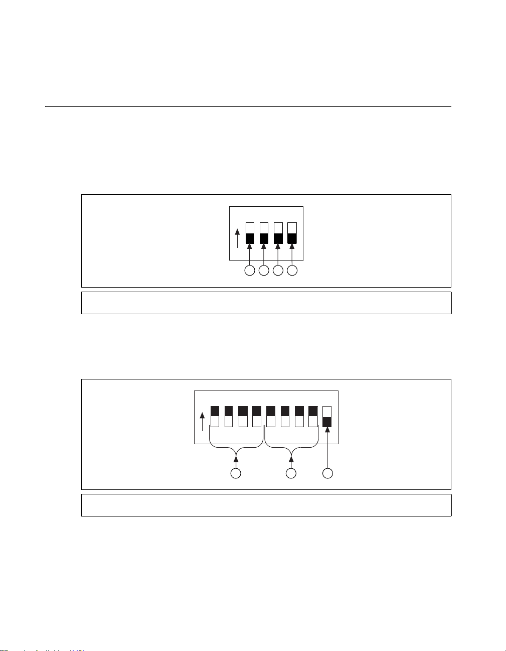
Front Panel DIP Switch Settings
The MID-7654/7652 front panel has a detachable metal plate that, when removed, provides access to
one 4-position DIP switch bank and either four (MID-7654) or two (MID-7652) 9-position DIP switch
banks. Refer to Figure 1 for the location of these switches.
Use the DIP switches on the 4-position DIP switch bank to configure the inhibit in, inhibit out, and limit
status LED polarity as shown in Figure 2. The different settings for these switches are described in the
following sections.
1 Inhibit In Polarity Switch
2 Inhibit Out Polarity Switch
Use the DIP switches on each 9-position DIP switch bank to configure the continuous current limit,
the peak current limit, and the motor inductance (low or standard) for each axis, as shown in Figure 3.
The different settings for these switches are described in the following sections.
1 Continuous Current Limit Switches
2 Peak Current Limit Switches
3 Limit Status LED Polarity Switch
4 Reserved
Figure 2. 4-Position DIP Switch Bank Layout
3 Motor Inductance Switch
Figure 3. 9-Position DIP Switch Bank Layout
MID-7654/7652 Servo Power Motor Drive User Guide 8 ni.com
Page 10

Inhibit Input Polarity Setting
1
O
N
1
O
N
3
O
N
3
O
N
Use DIP switch 1 on the 4-position DIP switch bank to globally set the polarity for the inhibit input for
all axes. Refer to Figures 1 and 3 for the location of this switch.
The factory-default setting of DIP switch 1 is active-low. If the inhibit input is active, the axis is inhibited
and the yellow status LED (middle row) corresponding to that axis illuminates. Table 2 shows the DIP
switch setting for the inhibit input polarity selection.
Switch Setting Operation
Inhibit Output Polarity Setting
Use DIP switch 2 on the 4-position DIP switch bank to globally set the polarity for the inhibit output for
all axes. Refer to Figures 1 and 3 for the location of this switch.
The factory-default setting of DIP switch 2 is active-high. Table 3 shows the DIP switch setting for the
inhibit output polarity selection.
Switch Setting Operation
Table 2. Inhibit Input Polarity DIP Switch Settings
Active-high
Active-low
(factory default)
Table 3. Inhibit Output Polarity DIP Switch Settings
Active-high
(factory default)
Active-low
Limit Status LED Polarity Setting
Use DIP switch 3 on the 4-position DIP switch bank to globally set the polarity for the Limit Status
LED. Refer to Figures 1 and 3 for the location of this switch.
The factory-default setting is active-high. Typically, you set the switch to match the polarity setting on
your controller, so if either the reverse or forward limits for an axis are active, the green status LED (on
the bottom row) corresponding to that axis illuminates. This DIP switch alters only the polarity for the
LEDs, not the actual limit to the motion controller. Table 4 shows the DIP switch setting for the Limit
Status LED polarity selection.
© National Instruments Corporation 9 MID-7654/7652 Servo Power Motor Drive User Guide
Page 11

Table 4. Limit Status LED DIP Switch Settings
2
O
N
2
O
N
Switch Setting Operation
Setting Continuous and Peak Current Limits
The MID-7654/7652 uses high-efficiency PWM amplifiers configured as torque blocks (current
amplifiers or transconductance amplifiers). The peak current limit is the maximum current your motor
can withstand for short periods of time. The continuous current limit is the maximum current your motor
can withstand indefinitely.
Caution To avoid overheating the drive under a motor fault condition, ensure the following error
limit is set above zero in the motion controller configuration software. The default following error
limit is 32,767.
Figure 4 illustrates the command voltage input to current output relationship for periods of time less than
2.7 seconds.
Active-high
(factory default)
Active-low
+I
peak
+V
max
0 V
+I
0 A
cont
Output Current
–I
Input Command Voltage
–V
max
Gain Applied
cont
–I
peak
Figure 4. Input Voltage to Output Current Relationship for Periods of Time Less Than 2.7 Seconds
MID-7654/7652 Servo Power Motor Drive User Guide 10 ni.com
Page 12

Figure 5 shows the command voltage input to current output relationship for periods of time greater than
1
O
N
234
1
O
N
234
1
O
N
234
1
O
N
234
1
O
N
234
1
O
N
234
2.7 seconds. The maximum current output corresponds to the continuous current limit, I
command voltages that would result in a higher current output than I
+V
cont
max
.
result in a current output of I
when the gain is applied instead
cont
+I
peak
+I
cont
. Therefore,
cont
0 V
0 A
Output Current
–I
Input Command Voltage
–V
max
Gain Applied
cont
–I
peak
Figure 5. Input Voltage to Output Current Relationship for Periods of Time Greater Than 2.7 Seconds
The amplifier peak and continuous current limits have been factory set for 5 A continuous current output
and 10 A peak current output. Verify that these settings are appropriate for your application before
powering your motors.
Use DIP switches 1 through 4 on each of the 9-position DIP switch banks to set the continuous current
limit for each axis. Use DIP switches 5 through 8 on each of the 9-position DIP switch banks to set the
peak current limit for each axis. Refer to Figures 1 and 3 for the location of the continuous current limit
and peak current limit switches. Table 5 shows the DIP switch settings for all possible current limit
settings.
Note The switches shown in Table 5 show the settings for switches 1 through 4, which are the
continuous current DIP switches. Configure the settings for switches 5 through 8 in the same manner
to set the peak current values.
Table 5. Continuous and Peak Output Current DIP Switch Settings
Switch
Continuous
Current (A)
Peak
Current (A)
Switch
Continuous
Current (A)
Current (A)
5.00 10.00 1.25 2.50
Peak
4.50 9.00 1.15 2.30
3.80 7.55 1.10 2.20
© National Instruments Corporation 11 MID-7654/7652 Servo Power Motor Drive User Guide
Page 13

Switch
1
O
N
234
1
O
N
234
1
O
N
234
1
O
N
234
1
O
N
234
1
O
N
234
1
O
N
234
1
O
N
234
1
O
N
234
1
O
N
234
Table 5. Continuous and Peak Output Current DIP Switch Settings (Continued)
Continuous
Current (A)
Peak
Current (A)
Switch
Continuous
Current (A)
3.00 6.00 1.05 2.10
2.45 4.90 1.00 1.95
2.10 4.20 0.95 1.85
1.95 3.85 0.90 1.80
Peak
Current (A)
1.70 3.45 0.85
(default)
1.70
(default)
If you are connecting multiple motors to your MID-7654/7652, verify that the total power dissipated by
the motors at any given time is less than the total power the drive can provide. If the total power
requirement exceeds the capability of the drive at any point, the drive will provide less power to the
motors than desired until the total power requirement drops back down. Your MID-7654/7652 may
overheat under continuous operation with loads that exceed specified limits.
Caution A fire safety hazard exists when the total power dissipated by the motors exceeds 400 W at
25% duty cycle for a sustained period of time.
To determine the maximum total power dissipation of all of the motors combined, add up the maximum
power each motor can dissipate. If this value is less than or equal to 400 W at 25% duty cycle, you will
not exceed the capabilities of the MID-7654/7652.
If the value is greater than 400 W at 25% duty cycle, you may still be within the operating capabilities
of the MID-7654/7652, since it is unlikely you will run all of your motors simultaneously at their
maximum levels. Make a reasonable estimation of the maximum power your motors will require at any
given time and verify that this value is less than 400 W at 25% duty cycle.
MID-7654/7652 Servo Power Motor Drive User Guide 12 ni.com
Page 14

Setting Motor Inductance Levels
9
O
N
9
O
N
Depending on the construction of your motor, you may need to configure one or more axes to the low
inductance setting rather than the default standard inductance setting. Table 6 shows the motor
inductance level ranges for the two different settings.
Motor Inductance MID-7654/7652 Setting
Greater than 440 μH Standard
Between 110 and 440 μH Low
Use the last DIP switch on each of the 9-position DIP switch banks to set the motor inductance level for
each axis. Refer to Figures 1 and 3 for the location of the of the motor inductance level switch. Table 7
shows the DIP switch settings for low and standard motor inductance.
Table 7. Motor Inductance Level DIP Switch Settings
Switch Setting Operation
Table 6. Motor Inductance Levels
Low motor inductance
Standard motor inductance
(factory default)
© National Instruments Corporation 13 MID-7654/7652 Servo Power Motor Drive User Guide
Page 15

Back Panel Connector Wiring
MID-7654
MID-7652
Figure 6 shows the MID-7654/7652 back panel connectors without their rear guards.
1 Motion Controller Connector
2 Analog Input Connector
3 Analog Output Connector
4 Trigger Connector
5 Breakpoint Connector
6 Step/Direction Connector
7AC Power
Encoder Connectors
8Axis 1
9Axis 2
10 Axis 3*
11 Axis 4*
Limit Connectors
12 Axis 1
13 Axis 2
14 Axis 3*
15 Axis 4*
Motor Connectors
16 Axis 1
17 Axis 2
18 Axis 3*
19 Axis 4*
Figure 6. MID-7654/7652 Back Panel Connectors
Note Items followed by an asterisk (*) are available on the MID-7654 only.
Caution Be sure to turn off the ENABLE and AC POWER switches for your MID-7654/7652 and
host computer and disconnect the unit from the power outlet before making connections to your
motion controller.
MID-7654/7652 Servo Power Motor Drive User Guide 14 ni.com
Page 16

Caution The servo motor connectors on this drive are energized when the unit is powered on. The
1
2
3
4
5
Motor +
Motor –
Motor Case Ground
+–
Shield
Servo Motor
rear guard must be in place at all times while the unit is connected to a power outlet. Disconnect the
MID-7654/7652 unit from power outlet before connecting wires to or disconnecting wires from
the servo motor connectors. Strip back the insulation of the servo motor wires to the servo motor
connectors no more than 7 mm. Reattach the rear guard before you reconnect the unit to a power
outlet. Failure to do so could result in electric shock leading to serious bodily injury or death. Refer
to the Rear Guard section of this guide for information on using the rear guard.
Take the following steps to wire your motion system to your MID-7654/7652:
1. Connect the motion controller to the MID-7654/7652 using the interface cable. Wire the motor
power, limit switch, encoder, and I/O terminal blocks to your motion control system.
2. For proper operation, configure the power entry module to match the voltage of your power source.
Refer to the Modifying the Power Entry Module section for more information.
Caution You must change the MID-7654/7652 main input fuse on the rear panel if you change the
line voltage from the factory setting. Refer to the Replacing a Fuse section in the Modifying the
Power Entry Module section of this guide for information on changing a fuse.
3. Install the power cord into the back panel AC connector and plug it into a correctly rated power
source.
Terminal Block Wiring
This section describes how to wire the terminal blocks on your MID-7654/7652.
Servo Motor Power Terminal Blocks
For motor power wiring, each MID-7654/7652 axis has a separate 5-position removable screw terminal
block. Figure 7 shows a typical servo motor configuration pin assignment. The dotted loop indicates a
shielded cable.
You should use shielded 20 AWG wire or larger for the motor power cable. If available, connect a motor
case ground wire to pin 3 (Ground/Shield) on the MID-7654/7652 as shown in Figure 7; this wire helps
avoid ground loops and signal noise problems. (Case ground connects to the motor housing, not to any
of the motor power terminals.)
© National Instruments Corporation 15 MID-7654/7652 Servo Power Motor Drive User Guide
Figure 7. Typical Servo Motor (DC Brush Type) Terminal Block Pin Assignment
Caution The servo motor connectors on this drive are energized when the unit is powered on. The
rear guard must be in place at all times while the unit is connected to a power outlet. Disconnect the
MID-7654/7652 unit from power outlet before connecting wires to or disconnecting wires from
the servo motor connectors. Strip back the insulation of the servo motor wires to the servo motor
connectors no more than 7 mm. Reattach the rear guard before you reconnect the unit to a power
outlet. Failure to do so could result in electric shock leading to serious bodily injury or death. Refer
to the Rear Guard section of this guide for information on using the rear guard.
Page 17

Caution Never connect unused center taps or winding terminals to pin 3.
CCW
CW
Depending on your motor, you may need to reverse the connections shown in Figure 7, as there is no
industry standard for direction of movement relative to the positive and negative motor inputs. Table 8
shows the National Instruments motion control standard directional polarity.
Table 8. National Instruments Standard Directional Polarity
Commanded
Direction Description Motor Signal Relationship Command Signal
Forward Clockwise (CW) facing motor
shaft
Reverse Counter-clockwise (CCW)
facing motor shaft
Motor – is greater than
Motor +
Motor + is greater than
Motor –
Positive voltage
Negative voltage
Figure 8 shows clockwise and counter-clockwise motor rotation.
Figure 8. Clockwise and Counter-Clockwise Motor Rotation
Rear Guard
The rear guard consists of the protection cover, protection plates, and bottom mounting plate as shown
in Figure 9.
MID-7654/7652 Servo Power Motor Drive User Guide 16 ni.com
Page 18

1 Bottom Mounting Plate 2 Protection Cover 3 Protection Plate
NATIONAL
INSTRUMENTS
Figure 9. Rear Guard Consisting of the Protection Cover, Protection Plates, and Bottom Mounting Plate
The rear guard installed on the MID-7654/7652 is shown in Figure 10.
Figure 10. Rear Guard Installed on the MID-7654/7652
© National Instruments Corporation 17 MID-7654/7652 Servo Power Motor Drive User Guide
Page 19

Caution The servo motor connectors on this drive are energized when the unit is powered on. The
2
rear guard must be in place at all times while the unit is connected to a power outlet. Disconnect the
MID-7654/7652 unit from power outlet before connecting wires to or disconnecting wires from
the servo motor connectors. Strip back the insulation of the servo motor wires to the servo motor
connectors no more than 7 mm. Reattach the rear guard before you reconnect the unit to a power
outlet. Failure to do so could result in electric shock leading to serious bodily injury or death.
Follow these steps carefully to ensure safe operation of your MID-7654/7652:
1. Ensure that the MID-7654/7652 is powered off and disconnected from the power outlet before
wiring any cables to the unit. The +5V green LED should not be illuminated after the
MID-7654/7652 is powered off and disconnected from the power outlet.
2. Ensure that the bottom mounting plate of the rear guard is securely fastened to both sides of the
MID-7654/7652, as shown in Figure 10.
3. Remove the protection plates for the axes to be used, rotate, and re-install the protection plates in
the open position, as shown in Figure 11.
1 Protection Cover 2 Protection Plate
Figure 11. Protection Cover and Protection Plates: Used Axes 1 & 2, Unused Axes 3 & 4.
Note The protection plates for any unused axes should remain installed in the closed position at all
times, as shown on axes 3 and 4 in Figure 11. For axes you are using, the protection plates must be
removed, rotated, and re-installed in the open position, as shown on axes 1 and 2 in Figure 11.
Contact your National Instruments sales representative to replace lost protection plates
(part number 188063A-01).
4. Remove the protection cover using the following procedure:
a. Remove the two screws that attach the protection cover to the side of the bottom mounting
plate, as shown in Figure 10.
b. Lift the protection cover from the slot on the bottom mounting plate, as shown in Figure 9.
MID-7654/7652 Servo Power Motor Drive User Guide 18 ni.com
Page 20

5. Plug the servo motor cables into the servo motor terminals of the MID-7654/7652. The cables must
1
2
3
4
5
6
7
8
Encoder A
Encoder B
Encoder Index
+5 V
Digital Ground
1
2
3
4
5
6
7
8
Encoder A
Encoder A
Encoder B
Encoder B
Encoder Index
Encoder Index
+5 V
Digital Ground
be placed over the bottom mounting plate of the rear guard.
6. Re-attach the protection cover
a. Insert the tab of the protection cover, shown in Figure 9, into the slot on the bottom mounting
plate.
b. Lower the protection cover over the servo motor cables and secure it to the side of the bottom
mounting plate using the two screws you removed in step 4.
7. Ensure that the rear guard is held securely in place before reconnecting your MID-7654/7652 to a
power outlet.
Encoder Terminal Blocks
For quadrature incremental encoder signals, each MID-7654/7652 axis has a separate 8-position
removable screw terminal block. Where applicable, the MID-7654/7652 accepts two types of encoder
signal inputs: single-ended (TTL) or differential line driver. You can accommodate open-collector
output encoders by using 2.2 kΩ pullup resistors to +5 VDC.
Figure 12 shows the typical encoder wiring pin assignment for single-ended signal input.
Note The dotted loop indicates a shielded cable. A line above a signal indicates that the signal is
active low.
Figure 12. Typical Single-Ended Encoder Wiring Pin Assignment
Figure 13 shows the typical encoder wiring pin assignment for differential line driver signal inputs.
Figure 13. Typical Differential Line Driver Encoder Wiring Pin Assignment
If the encoder cable length is greater than 10 ft, use encoders with line driver outputs for your
applications. Power for a +5 V encoder—generated by a power supply inside the MID-7654/7652—is
available on pin 7.
© National Instruments Corporation 19 MID-7654/7652 Servo Power Motor Drive User Guide
Page 21

Note If you require other encoder power voltages, reference an external power supply to the Digital
Phase A
Phase B
Index
Shield
+5 V
Encoder Index
Encoder Index
Encoder B
Encoder B
Encoder A
Drain
Encoder A
Digital
Ground
Ground signal on the 8-pin encoder terminal block.
The MID-7654/7652 supports differential inputs for Phase A, Phase B, and Index signals. You can easily
accommodate encoders with various phase relationships by swapping the signals and/or connecting
them to the inverting inputs as required by your application. The Index signal must occur when both
Phase A and Phase B signals are low, as shown in Figure 14. If the Index polarity is inverted, try
reversing the Index and Index
signals on differential encoders or using the Index input on single-ended
encoders.
Figure 14 shows the proper encoder phasing for CW (forward) motor rotation.
Figure 14. Encoder Signal Phasing, CW Rotation
Closed-loop servo applications require consistent directional polarity between the motor and encoder
for correct operation. The National Instruments motion control standard directional polarity is as
follows:
• Positive = forward = clockwise (CW) facing motor shaft
• Negative = reverse = counter-clockwise (CCW) facing motor shaft
Refer to Figure 8 for a depiction of clockwise and counter-clockwise rotation.
When connecting the encoder wiring to your MID-7654/7652, use shielded wire of at least 24 AWG.
You must use cables with twisted pairs and an overall shield for improved noise immunity and enhanced
encoder signal integrity. Figure 15 shows twisted pairs in a shielded cable.
MID-7654/7652 Servo Power Motor Drive User Guide 20 ni.com
Figure 15. Shielded Twisted Pairs
Page 22

Note Using an unshielded cable may produce noise, which can corrupt the encoder signals and
1
6
2
3
4
5
Forward Limit
Home Input
Inhibit Input
Digital Ground
Reverse Limit
Inhibit Output
1
2
3
4
5
6
Trigger Input 1
Trigger Input 2
Trigger Input 4
Digital Ground
Trigger Input 3
Shutdown Input
1
2
3
4
5
6
Breakpoint Output 1
Breakpoint Output 2
Breakpoint Output 4
Digital Ground
Breakpoint Output 3
+5 V
cause lost counts, reduced accuracy, or other erroneous encoder and controller operation.
Limit Switch Terminal Blocks
For end-of-travel limit, home, inhibit input, and inhibit output connections, MID-7654/7652 axes have
a separate, 6-position removable screw terminal connector block. Figure 16 shows the limit switch
terminal block pin assignments.
Figure 16. Limit Switch Terminal Block Pin Assignment
(Passive Limit Switch Connection Example)
You can configure the inhibit output signal to be asserted low or asserted high from the MID-7654/7652
when an axis is inhibited. This signal can be useful for actuating mechanical brakes or for monitoring
an axis status. Refer to the Amplifier Inhibit LEDs section of this guide for a description of the
conditions that will cause an axis to be inhibited.
Breakpoint and Trigger Terminal Blocks
Both the breakpoint and trigger connectors use a 6-pin removable terminal block.
© National Instruments Corporation 21 MID-7654/7652 Servo Power Motor Drive User Guide
The trigger terminal block provides access to the trigger input lines, shutdown input line, and digital
ground. The breakpoint terminal block provides access to the breakpoint output lines, the +5 V supplied
by the MID-7654/7652, and the digital ground. Figures 17 and 18 show the breakpoint and trigger
6-position terminal block assignments.
Figure 17. Trigger Terminal Block Pin Assignment
Figure 18. Breakpoint Terminal Block Pin Assignment
Page 23

Analog I/O Terminal Blocks
1
2
3
4
5
6
Analog Input 1
Analog Input 2
Analog Input 4
Analog Input Ground
Analog Input 3
Analog Reference (Output)
1
2
3
4
5
Analog Output 1
Analog Output 2
Analog Output 4
Analog Output 3
Analog Output Ground
1
2
3
4
5
6
7
8
Step 1
Direction 1
Direction 2
Direction 3
Step 2
Step 3
Direction 4
Step 4
The MID-7654/7652 features two analog I/O connectors.
The analog input connector uses a 6-pin removable terminal block, which provides access to
four analog-to-digital converter channels, an analog reference voltage from the converter circuit,
and an analog input ground signal.
The analog output connector uses a 5-pin removable terminal block, which provides access to
four digital-to-analog converter channels and analog output ground. Refer to Figures 19 and 20 for
terminal block pin assignments.
Figure 19. Analog Input Terminal Block Pin Assignment
Step and Direction Terminal Block
The MID-7654/7652 passes step and direction signals from the controller directly through the drive,
allowing you to access them through the 8-pin removable terminal block. This feature is useful if your
system includes both stepper and servo motors, as it reduces the amount of custom cabling required to
connect your motors and drives to the controller.
To use the step and direction connector, select an unused axis on the MID-7654/7652 and connect the
step and direction outputs for that axis to your stepper drive. Refer to Figure 21 for the terminal block
pin assignments. Connect additional signals for the axis, such as inhibit outputs, limit switches,
breakpoints and triggers, and encoder feedback, as described earlier in this guide.
MID-7654/7652 Servo Power Motor Drive User Guide 22 ni.com
Figure 20. Analog Output Terminal Block Pin Assignment
Figure 21. Step and Direction Terminal Block Pin Assignment
Page 24

Cable Installation for CE Compliance
2
3
1
Take the following additional steps to ensure CE Compliance:
1. Enclose the terminal block wires in a 360-degree shielded cable. This requires a braided shield.
2. Install the strain-relief bar on the MID-7654/7652 as described in the Accessories Included for
Optional Use section of this guide.
3. Place all cables connecting to the back panel through the strain-relief bar, as follows:
a. All servo motor cables must pass through the far right clamp on the strain-relief bar, which is
directly aligned with the servo motor terminals and protection cover.
b. All remaining cables should pass through the three clamps to the left of the servo motor
terminals.
c. Cables passing through the same clamp must be of the same cable diameter.
d. Cables passing through the same clamp must be parallel and must not overlap each other,
as shown in Figure 22.
4. All cables must be properly grounded to the strain-relief bar, which grounds them to the
MID-7654/7652 chassis ground. Follow these steps to ground the cables to the strain-relief bar:
a. Remove the outer jacket from the section of the cable to be inserted between the strain-relief
bar clamp and foam, as shown in Figure 22. This will expose the braided shield of the cable.
Note Do not cut the braided shield of the cable.
1 Braided Shield of the Cable 2 Strain Relief Bar 3 Terminal Block Connector
Figure 22. Required Cabling for CE Compliance
b. Lay the cables so that the braided shield makes full contact with the foam of the strain-relief
bar. The braided shield must only make contact with the strain-relief bar, and no other part of
the device.
c. Lower the clamp and tighten the thumb nuts to remove all gaps between the foam and the
cable shields. The foam should press around the shield of the cable to provide 360-degree
grounding to the cable shield.
5. Ground the braided shield at the opposite end of the cables to your destination enclosure ground.
© National Instruments Corporation 23 MID-7654/7652 Servo Power Motor Drive User Guide
Page 25

Accessories Included for Optional Use
1
2
Strain-Relief Bar Installation
The strain-relief bar provides strain relief for wiring to the back panel terminals of the MID-7654/7652.
It must be used to provide necessary grounding for CE compliance. Refer to the Cable Installation for
CE Compliance section of this guide for more information.
The arms of the strain-relief bar attach between the sides of the MID-7654/7652 and the bottom
mounting plate of the rear guard with the thumb nuts facing upwards, as shown in Figure 23. Refer to
the Rear Guard section of this guide for more information on removing and replacing the protection
cover from the rear guard. Refer to Figure 23 while following these strain-relief bar installation steps:
1. Remove the protection cover of the rear guard.
2. Place the strain-relief bar so it fits within the sides of the bottom mounting plate.
3. Attach the strain-relief bar to the side panels of the MID-7654/7652 using the provided screws.
4. Replace the protection cover.
1 Rear Guard Assembly 2 Strain Relief Bar
Figure 23. MID-7654/7652 with the Strain-Relief Bar Installed
MID-7654/7652 Servo Power Motor Drive User Guide 24 ni.com
Page 26

Panel Mount Kit Installation
The panel mount kit allows you to mount the MID-7654/7652 inside a cabinet or enclosure. Attach the
panel mount kit to the rear and front set of screw holes on the side panels of the MID-7654/7652,
as shown in Figure 24, using the provided screws.
INSTRUMENTS
NATIONAL
1
1 Rear Guard Assembly 2 Panel Mount
Figure 24. MID-7654/7652 with the Panel Mount Kit Installed
Note The strain-relief bar and panel mount kit cannot be installed at the same time, because they
will not simultaneously fit under the sides of the bottom mounting plate.
Modifying the Power Entry Module
This section covers replacing fuses and switching the line voltage for your drive.
Replacing a Fuse
Follow these steps to replace a fuse on your MID-7654/7652:
1. Pry open the hinged cover on the power entry module (number 7 in Figure 6).
2. Remove the fuse holder. Notice how the fuse holder is oriented so you can replace it properly.
3. Replace the blown fuse in the fuse holder. Be sure the new fuse is oriented in the same way as the
original fuse, and that it is rated at the proper voltage.
4. Push the fuse holder back into the power entry module with the same orientation you observed in
step 2.
5. Close the hinged cover.
2
© National Instruments Corporation 25 MID-7654/7652 Servo Power Motor Drive User Guide
Page 27

Changing the Line Voltage
Follow these steps to change the line voltage on your MID-7654/7652:
1. Pry open the hinged cover on the power entry module (number 7 in Figure 6).
2. Remove the fuse holder.
3. Replace the two fuses with the appropriate fuses for the desired line voltage as listed in the
Specifications section.
4. Rotate the fuse holder 180 degrees so the desired line voltage number shows through the window
when the power module cover is closed.
5. Push the fuse holder back into the power entry module with the new orientation.
6. Close the hinged cover.
Amplifier/Driver Command Signals
The PWM amplifiers used in the MID-7654/7652 accept an industry-standard ±10 V analog torque
(current) command signal. Servo motion controllers used with the MID-7654/7652 provide this standard
output and are programmed to close both the velocity loop and position loop using an enhanced
PID algorithm.
Specifications
The following specifications apply only to the MID-7654/7652. You must account for your motion
controller to obtain a system specification. Refer to your controller specifications to determine overall
system specifications.
Some signals define compatibility as signal pass-through, which means the MID-7654/7652 may use
passive filtering on these signals. This will not affect the voltage range or current handling capability.
Consult your motion controller specifications to determine the allowable voltage range and logic level
compatibility of the signal.
Servo Amplifiers
Type........................................................................Elmo Motion Control VIO 10/100
Peak current limit (2.7 s)........................................1.7–10 A (default 1.7 A)
Continuous current limit ........................................0.85–5 A (default 0.85 A)
DC-bus motor voltage............................................48 VDC
PWM frequency.....................................................32 kHz
Continuous power output rating
(all axes combined) ................................................400 W at 25% duty cycle
Encoders
Inputs .....................................................................Quadrature, incremental
Differential input threshold....................................± 0.3 V (typical)
Single ended input threshold..................................TTL/CMOS
Voltage range ......................................................... 0–5 VDC
Maximum quadrature frequency............................ 20 MHz
MID-7654/7652 Servo Power Motor Drive User Guide 26 ni.com
Page 28

Limit and Home Switch Inputs
Compatibility .........................................................Signal pass-through
Inhibit Inputs
Voltage range .........................................................0–12 VDC
Input low voltage ...................................................0.8 V
Input high voltage ..................................................2 V
Inhibit Outputs
Voltage range .........................................................0–5 VDC
Output low voltage.................................................0.5 V at 64 mA
Output high voltage................................................2.4 V at 32 mA
Trigger Input
Noise filter (RC time constant)..............................100 ns
Compatibility .........................................................Signal pass-through
Breakpoint Outputs
Compatibility .........................................................Signal pass-through
Analog Inputs
Noise filter (RC time constant)..............................10 μs
Compatibility .........................................................Signal pass-through
Analog Outputs
Compatibility .........................................................Signal pass-through
Step/Direction Outputs
Compatibility .........................................................Signal pass-through
Shutdown Input
Compatibility .........................................................Signal pass-through
User 5 V Supply
Voltage range @ 0.5 A...........................................4.7 to 5.2 V
Included Connectors
Encoders.................................................................8-position mini-combicon 3.81 mm plug (1 per axis)
Limits .....................................................................6-position mini-combicon 3.81 mm plug (1 per axis)
Servo Motors..........................................................5-position combicon 5.08 mm plug (1 per axis)
Breakpoints ............................................................6-position mini-combicon 3.81 mm plug (1 total)
Triggers ..................................................................6-position mini-combicon 3.81 mm plug (1 total)
Step/Direction ........................................................8-position mini-combicon 3.81 mm plug (1 total)
Analog input ..........................................................6-position mini-combicon 3.81 mm plug (1 total)
© National Instruments Corporation 27 MID-7654/7652 Servo Power Motor Drive User Guide
Page 29

Analog output ........................................................5-position mini-combicon 3.81 mm plug (1 total)
AC power ...............................................................Detachable AC power cord (IEC standard type)
Motion I/O .............................................................68-pin female high density VHDCI type
Power Supply
Input voltage ..........................................................90–132 VAC / 198–264 VAC, 47–63 Hz
Input fuse
115 VAC (factory default)..............................8 A (Littelfuse #312008)
230 VAC.........................................................6 A (Littelfuse #312006)
Input fuse dimensions ............................................0.25 in. × 1.25 in.
Input Power Peak Current (at max load)
115 VAC.........................................................10 A
230 VAC.........................................................5 A
Installation category...............................................II
Environment
Operating temperature ...........................................0 to 50 °C (32 to 122 °F)
Storage temperature ...............................................–20 to 70 °C (– 4 to 158 °F)
Humidity ................................................................10% to 90% RH, noncondensing
Maximum altitude.................................................. 2,000 m
Pollution Degree ....................................................2
Host Bus Voltage Interlock
Undervoltage threshold..........................................4 VDC
Physical
Dimensions (W × H × L) .......................................25.4 cm × 8.8 cm × 30.6 cm
(10 in. × 3.5 in. × 12.0 in.)
Weight ....................................................................10.2 kg (22.5 lb.)
Safety
This product is designed to meet the requirements of the following standards of safety for electrical
equipment for measurement, control, and laboratory use:
• EN 61010-1:1993/A2:1995, IEC 61010-1:1990/A2:1995
• UL 3101-1:1993, UL 3111-1:1994, UL 3121-1:1998
• CAN/CSA C22.2 No. 1010.1:1992/A2:1997
UL Recognized to UL 508C, power conversion equipment, File # E208822
Note For UL and other safety certifications, refer to the product label or the Online Product
Certification section.
MID-7654/7652 Servo Power Motor Drive User Guide 28 ni.com
Page 30

Electromagnetic Compatibility
⬉ᄤֵᙃѻક∵ᶧࠊㅵ⧚ࡲ⊩ ˄Ё
RoHS
˅
Ёᅶ᠋
National Instruments
ヺড়Ё⬉ᄤֵᙃѻકЁ䰤ࠊՓ⫼ᶤѯ᳝ᆇ⠽䋼ᣛҸ
(RoHS)
DŽ
݇Ѣ
National InstrumentsЁRoHS
ড়㾘ᗻֵᙃˈ䇋ⱏᔩ
ni.com/environment/rohs_china
DŽ
(For information about China RoHS compliance, go to
ni.com/environment/rohs_china
.)
This product meets the requirements of the following EMC standards for electrical equipment for
measurement, control, and laboratory use:
• EMC/EMI: CE, C-Tick and FCC Part 15 (Class A) Compliant.
• Electrical emissions: EN 55011 Class A @ 10 meters FCC Part 15A above 1 GHz.
• Electrical immunity: Evaluated to EN 61326:1998, Table 1
Note For the standards applied to assess the EMC of this product, refer to the Online Product
Certification section.
Note For EMC compliance, operate this device according to the documentation.
CE Compliance
This product meets the essential requirements of applicable European Directives as follows:
• 2006/95/EC; Low-Voltage Directive (safety)
• 2004/108/EC; Electromagnetic Compatibility Directive (EMC)
Online Product Certification
Refer to the product Declaration of Conformity (DoC) for additional regulatory compliance
information. To obtain product certifications and the DoC for this product, visit ni.com/
certification
Certification column.
, search by module number or product line, and click the appropriate link in the
Environmental Management
National Instruments is committed to designing and manufacturing products in an environmentally
responsible manner. NI recognizes that eliminating certain hazardous substances from our products
is beneficial to the environment and to NI customers.
For additional environmental information, refer to the NI and the Environment Web page at
ni.com/environment. This page contains the environmental regulations and directives with
which NI complies, as well as other environmental information not included in this document.
Waste Electrical and Electronic Equipment (WEEE)
EU Customers At the end of the product life cycle, all products must be sent to a WEEE recycling
center. For more information about WEEE recycling centers, National Instruments WEEE initiatives,
and compliance with WEEE Directive 2002/96/EC on Waste and Electronic Equipment,
ni.com/environment/weee.
visit
© National Instruments Corporation 29 MID-7654/7652 Servo Power Motor Drive User Guide
Page 31

Where to Go for Support
The National Instruments Web site is your complete resource for technical support. At ni.com/
support
resources to email and phone assistance from NI Application Engineers.
A Declaration of Conformity (DoC) is our claim of compliance with the Council of the European
Communities using the manufacturer’s declaration of conformity. This system affords the user
protection for electromagnetic compatibility (EMC) and product safety. You can obtain the DoC for
your product by visiting
obtain the calibration certificate for your product at ni.com/calibration.
National Instruments corporate headquarters is located at 11500 North Mopac Expressway, Austin,
Texas, 78759-3504. National Instruments also has offices located around the world to help address your
support needs. For telephone support outside the United States, contact your local branch office. You
can visit the Worldwide Offices section of
which provide up-to-date contact information, support phone numbers, email addresses, and current
events.
you have access to everything from troubleshooting and application development self-help
ni.com/certification. If your product supports calibration, you can
ni.com/niglobal to access the branch office Web sites,
MID-7654/7652 Servo Power Motor Drive User Guide 30 ni.com
Page 32

LabVIEW, National Instruments, NI, ni.com, the National Instruments corporate logo, and the Eagle
logo are trademarks of National Instruments Corporation. Refer to the Trademark Information at
ni.com/trademarks for other National Instruments trademarks. Other product and company
names mentioned herein are trademarks or trade names of their respective companies. For patents
covering National Instruments products/technology, refer to the appropriate location: Help»Patents
in your software, the patents.txt file on your media, or the National Instruments Patent Notice
at ni.com/patents. Refer to the Export Compliance Information at ni.com/legal/
export-compliance for the National Instruments global trade compliance policy and how to
obtain relevant HTS codes, ECCNs, and other import/export data.
© 2000–2012 National Instruments Corporation. All rights reserved.
372902B-01 Jan12
 Loading...