

Page 1
USER GUIDE
MCA-7724 M
Introduction
The MCA-7724 Motion Axis Router reroutes the signals from your motion
controller into separate connectors that connect to different motion
accessories. The router allows you to connect one, two, three, and four axis
drives and accessories to a controller.
Features
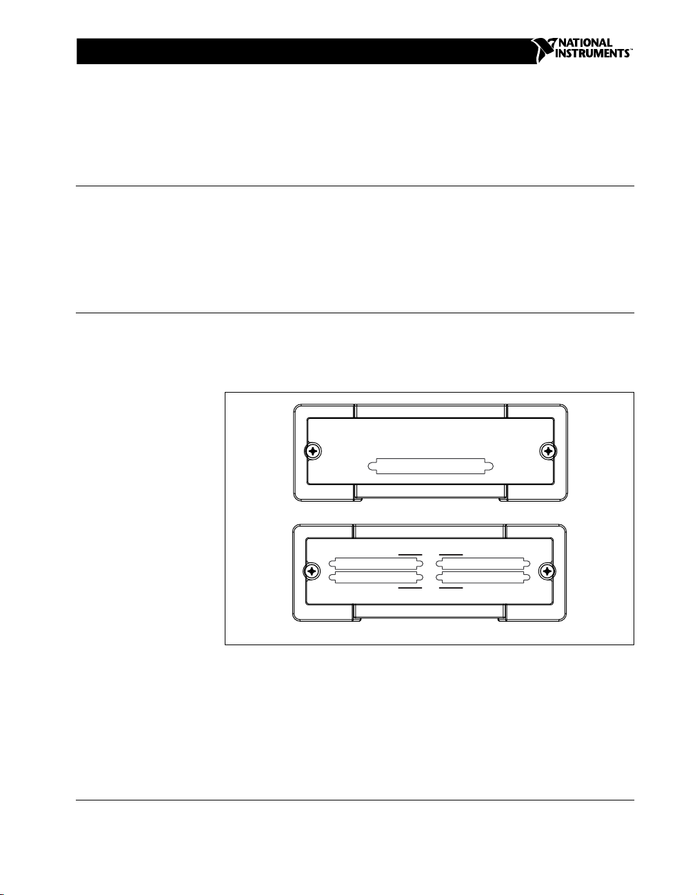
The MCA-7724 Motion Axis Router has five 68-pin VHDCI connectors:
the controller connector, connector A, connector B, connector C, and
connector D. Figure 1 shows the five connectors.
OTIONAXIS
R
OUTER
CONTROLLER CONNECTOR
MOTION I/O
Front
ACCESSORY CONNECTORS
<
CONNECTOR A
<
CONNECTOR C CONNECTOR D
Back
Figure 1. MCA-7724 Motion Axis Router Connectors
National Instruments™and ni.com™are trademarks of National Instruments Corporation. Product and company names mentioned herein are
trademarks or trade names of their respective companies.
322835A-01 Copyright © 2001 National Instruments Corp. All rights reserved. April 2001
2+2
3+1
>
CONNECTOR B
>
Page 2
Connectivity Options
The controller connector on the MCA-7724 Motion Axis Router connects
to the 68-pin motion I/O connector on your controller. The adapter then
reroutes signals from the motion I/O connector to the accessory connectors
on the MCA-7724 Motion Axis Router. You can connect motion drives and
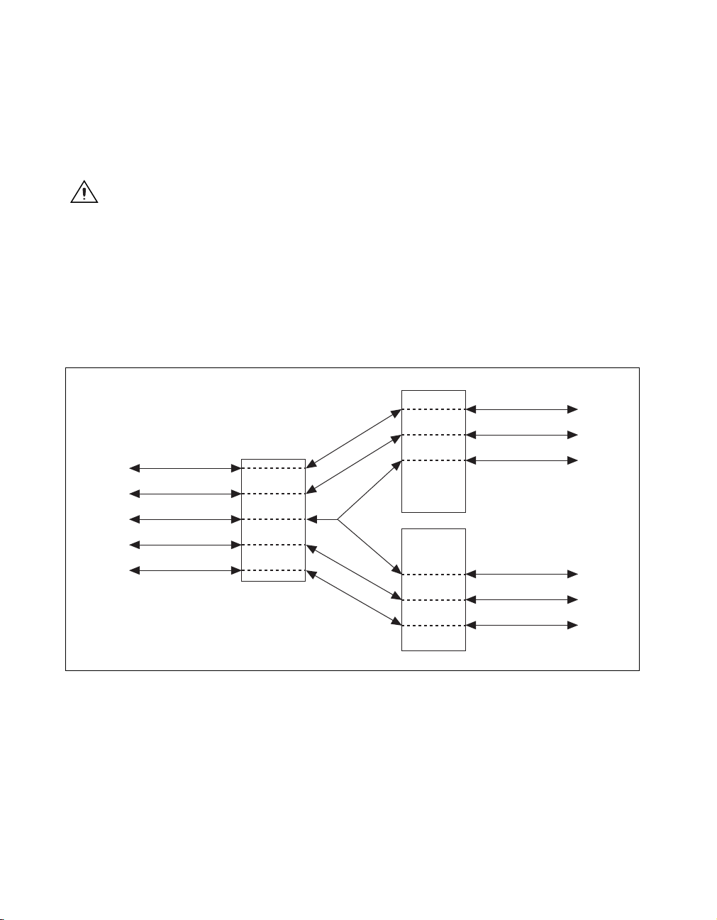
accessories in a 2 + 2 connectivity option or a 3 + 1 connectivity option.
Figures 2 and 3 show the two connectivity options.
Caution
Connect motion drives and accessories only to connectors A and B (2 + 2
connectivity option) or to connectors C and D (3 + 1 connectivity option). Failure to
connect the motion drives and accessories as shown in Figures 2 and 3 may result in
damage to the motion controller, axis router, drive, or accessory.
2+2ConnectivityOption
Controller axes 1 and 2 from the controller correspond to axes 1 and 2 on
connectorA,andcontrolleraxes3and4correspondtoaxes1and2on
connector B, as shown in Figure 2.
Axis 1 Signals
Axis 2 Signals
Shared Signals
Shared Signals
Axis 1 Signals
Axis 1 Signals
Axis 2 Signals
Shared Signals
Axis 3 Signals
To Controller
Axis 4 Signals
Controller
Connector
Axis 1 Signals
Axis 2 Signals
Shared
Signals
Axis 3 Signals
Axis 4 Signals
Connector
A
Connector
B
To Drive/AccessoryTo Drive/Accessory
Axis 2 Signals
Figure 2. 2 + 2 Connectivity Option
MCA-7724 Motion Axis Router 2 ni.com
Page 3
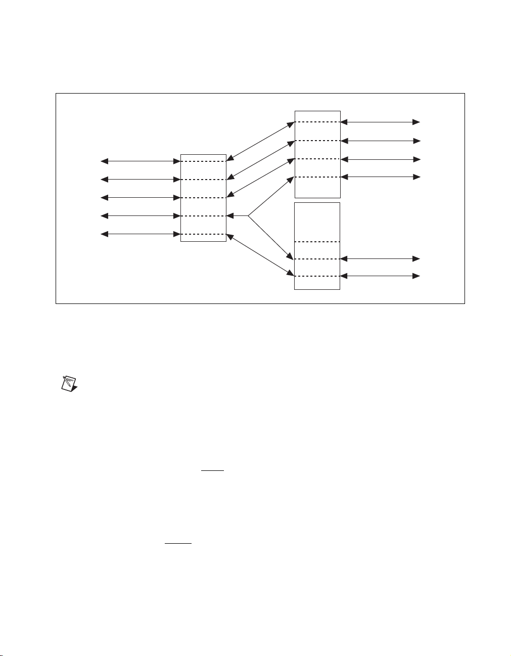
3+1ConnectivityOption
Controller axes 1, 2, and 3 correspond to axes 1, 2, and 3 on connector C,
and controller axis 4 corresponds to axis 1 on connector D, as shown in
Figure 3.
Axis 1 Signals
Axis 1 Signals
Axis 2 Signals
Axis 3 Signals
Shared Signals
To Controller
Axis 4 Signals
Note
Controller
Connector
Axis 1 Signals
Axis 2 Signals
Axis 3 Signals
Shared
Signals
Axis 4 Signals
Connector
C
Connector
D
Axis 2 Signals
Axis 3 Signals
Shared Signals
Shared Signals
Axis 1 Signals
Figure 3. 3 + 1 Connectivity Option
Axis Signals
The per axis and shared signals from the controller are listed below.
A line above the signal name indicates that the signal is active-low.
Per Axis Signals from the Controller
Step (CW)
Dir (CCW)
Encoder Phase A
Encoder Phase B
Encoder Index
Forward Limit Switch
Reverse Limit Switch
Home Switch
Trigger
Breakpoint
Inhibit
Analog Output
Analog Input
To Drive/Accessory
To Drive/Accessory
© National Instruments Corporation 3 MCA-7724 Motion Axis Router
Page 4

Shared Signals from the Controller
Host +5V
Digital Ground
Analog Input Ground
Analog Output Ground
Analog Reference (Output)
Shutdown
Some signals may not be available on your controller. Please consult your controller
Note
user manual for signal connection information.
Caution
double driving input signal shutdown.
Shared signals are available at all four accessory connectors. Use caution to avoid
Software Configuration
Because of signal rerouting, the axis number on your accessory may not
match the programmed axis in your software. With the 2 + 2 connectivity
option, the accessory connected to connector B will refer to the axes as
axis 1 and axis 2, but will be programmed as axis 3 and axis 4, respectively,
in your software. With the 3 + 1 connectivity option, the accessory
connected to connector D will refer to the axis as axis 1 but will be
programmed as axis 4 in your software.
MCA-7724 Motion Axis Router 4 ni.com
Page 5

Connecting Your Adapter
This section provides the pin assignments for each of the MCA-7724
connectors.
Figure 4 shows the pin assignments for the controller connector.
Axis 1 Dir (CCW)
Digital Ground
Digital Ground
Axis 1 Home Switch
Trigger 1
Axis 1 Inhibit
Axis 2 Dir (CCW)
Digital Ground
Digital Ground
Axis 2 Home Switch
Trigger 2
Axis 2 Inhibit
Axis 3 Dir (CCW)
Digital Ground
Digital Ground
Axis 3 Home Switch
Trigger 3
Axis 3 Inhibit
Axis 4 Dir (CCW)
Digital Ground
Digital Ground
Axis 4 Home Switch
Trigger 4
Axis 4 Inhibit
Digital Ground
Breakpoint 1
Breakpoint 3
Digital Ground
Analog Output 1
Analog Output 3
Analog Output Ground
Analog Input 1
Analog Input 3
Analog Reference (Output)
135
236
337
438
539
640
741
842
943
10 44
11 45
12 46
13 47
14 48
15 49
16 50
17 51
18 52
19 53
20 54
21 55
22 56
23 57
24 58
25 59
26 60
27 61
28 62
29 63
30 64
31 65
32 66
33 67
34 68
Axis 1 Step (CW)
Axis 1 Encoder Phase A
Axis 1 Encoder Phase B
Axis 1 Encoder Index
Axis 1 Forward Limit Switch
Axis 1 Reverse Limit Switch
Axis 2 Step (CW)
Axis 2 Encoder Phase A
Axis 2 Encoder Phase B
Axis 2 Encoder Index
Axis 2 Forward Limit Switch
Axis 2 Reverse Limit Switch
Axis 3 Step (CW)
Axis 3 Encoder Phase A
Axis 3 Encoder Phase B
Axis 3 Encoder Index
Axis 3 Forward Limit Switch
Axis 3 Reverse Limit Switch
Axis 4 Step (CW)
Axis 4 Encoder Phase A
Axis 4 Encoder Phase B
Axis 4 Encoder Index
Axis 4 Forward Limit Switch
Axis 4 Reverse Limit Switch
Host +5 V
Breakpoint 2
Breakpoint 4
Shutdown
Analog Output 2
Analog Output 4
Reserved
Analog Input 2
Analog Input 4
Analog Input Ground
Figure 4. 68-Pin Controller Connector Pin Assignments
© National Instruments Corporation 5 MCA-7724 Motion Axis Router
Page 6

Figure 5 shows the pin assignments for connector A.
Axis 1 Dir (CCW)
Digital Ground
Digital Ground
Axis 1 Home Switch
Trigger 1
Axis 1 Inhibit
Axis 2 Dir (CCW)
Digital Ground
Digital Ground
Axis 2 Home Switch
Trigger 2
Axis 2 Inhibit
NC
Digital Ground
Digital Ground
NC
NC
NC
NC
Digital Ground
Digital Ground
NC
NC
NC
Digital Ground
Breakpoint 1
NC
Digital Ground
Analog Output 1
NC
Analog Output Ground
Analog Input 1
NC
Analog Reference (Output)
135
236
337
438
539
640
741
842
943
10 44
11 45
12 46
13 47
14 48
15 49
16 50
17 51
18 52
19 53
20 54
21 55
22 56
23 57
24 58
25 59
26 60
27 61
28 62
29 63
30 64
31 65
32 66
33 67
34 68
Axis 1 Step (CW)
Axis 1 Encoder Phase A
Axis 1 Encoder Phase B
Axis 1 Encoder Index
Axis 1 Forward Limit Switch
Axis 1 Reverse Limit Switch
Axis 2 Step (CW)
Axis 2 Encoder Phase A
Axis 2 Encoder Phase B
Axis 2 Encoder Index
Axis 2 Forward Limit Switch
Axis 2 Reverse Limit Switch
NC
NC
NC
NC
NC
NC
NC
NC
NC
NC
NC
NC
Host +5 V
Breakpoint 2
NC
Shutdown
Analog Output 2
NC
Reserved
Analog Input 2
NC
Analog Input Ground
Figure 5. 68-Pin Connector A Pin Assignments
MCA-7724 Motion Axis Router 6 ni.com
Page 7

Figure 6 shows the pin assignments for connector B.
Axis 3 Dir (CCW)
Digital Ground
Digital Ground
Axis 3 Home Switch
Trigger 3
Axis 3 Inhibit
Axis 4 Dir (CCW)
Digital Ground
Digital Ground
Axis 4 Home Switch
Trigger 4
Axis 4 Inhibit
NC
Digital Ground
Digital Ground
NC
NC
NC
NC
Digital Ground
Digital Ground
NC
NC
NC
Digital Ground
Breakpoint 3
NC
Digital Ground
Analog Output 3
NC
Analog Output Ground
Analog Input 3
NC
Analog Reference (Output)
135
236
337
438
539
640
741
842
943
10 44
11 45
12 46
13 47
14 48
15 49
16 50
17 51
18 52
19 53
20 54
21 55
22 56
23 57
24 58
25 59
26 60
27 61
28 62
29 63
30 64
31 65
32 66
33 67
34 68
Axis 3 Step (CW)
Axis 3 Encoder Phase A
Axis 3 Encoder Phase B
Axis 3 Encoder Index
Axis 3 Forward Limit Switch
Axis 3 Reverse Limit Switch
Axis 4 Step (CW)
Axis 4 Encoder Phase A
Axis 4 Encoder Phase B
Axis 4 Encoder Index
Axis 4 Forward Limit Switch
Axis 4 Reverse Limit Switch
NC
NC
NC
NC
NC
NC
NC
NC
NC
NC
NC
NC
Host +5 V
Breakpoint 4
NC
Shutdown
Analog Output 4
NC
Reserved
Analog Input 4
NC
Analog Input Ground
Figure 6. 68-Pin Connector B Pin Assignments
© National Instruments Corporation 7 MCA-7724 Motion Axis Router
Page 8

Figure 7 shows the pin assignments for connector C.
Axis 1 Dir (CCW)
Digital Ground
Digital Ground
Axis 1 Home Switch
Trigger 1
Axis 1 Inhibit
Axis 2 Dir (CCW)
Digital Ground
Digital Ground
Axis 2 Home Switch
Trigger 2
Axis 2 Inhibit
Axis 3 Dir (CCW)
Digital Ground
Digital Ground
Axis 3 Home Switch
Trigger 3
Axis 3 Inhibit
NC
Digital Ground
Digital Ground
NC
NC
NC
Digital Ground
Breakpoint 1
Breakpoint 3
Digital Ground
Analog Output 1
Analog Output 3
Analog Output Ground
Analog Input 1
Analog Input 3
Analog Reference (Output)
135
236
337
438
539
640
741
842
943
10 44
11 45
12 46
13 47
14 48
15 49
16 50
17 51
18 52
19 53
20 54
21 55
22 56
23 57
24 58
25 59
26 60
27 61
28 62
29 63
30 64
31 65
32 66
33 67
34 68
Axis 1 Step (CW)
Axis 1 Encoder Phase A
Axis 1 Encoder Phase B
Axis 1 Encoder Index
Axis 1 Forward Limit Switch
Axis 1 Reverse Limit Switch
Axis 2 Step (CW)
Axis 2 Encoder Phase A
Axis 2 Encoder Phase B
Axis 2 Encoder Index
Axis 2 Forward Limit Switch
Axis 2 Reverse Limit Switch
Axis 3 Step (CW)
Axis 3 Encoder Phase A
Axis 3 Encoder Phase B
Axis 3 Encoder Index
Axis 3 Forward Limit Switch
Axis 3 Reverse Limit Switch
NC
NC
NC
NC
NC
NC
Host +5 V
Breakpoint 2
NC
Shutdown
Analog Output 2
NC
Reserved
Analog Input 2
NC
Analog Input Ground
Figure 7. 68-Pin Connector C Pin Assignments
MCA-7724 Motion Axis Router 8 ni.com
Page 9

Figure 8 shows the pin assignments for connector D.
Axis 4 Dir (CCW)
Digital Ground
Digital Ground
Axis 4 Home Switch
Trigger 4
Axis 4 Inhibit
NC
Digital Ground
Digital Ground
NC
NC
NC
NC
Digital Ground
Digital Ground
NC
NC
NC
NC
Digital Ground
Digital Ground
NC
NC
NC
Digital Ground
Breakpoint 4
NC
Digital Ground
Analog Output 4
NC
Analog Output Ground
Analog Input 4
NC
Analog Reference (Output)
135
236
337
438
539
640
741
842
943
10 44
11 45
12 46
13 47
14 48
15 49
16 50
17 51
18 52
19 53
20 54
21 55
22 56
23 57
24 58
25 59
26 60
27 61
28 62
29 63
30 64
31 65
32 66
33 67
34 68
Axis 4 Step (CW)
Axis 4 Encoder Phase A
Axis 4 Encoder Phase B
Axis 4 Encoder Index
Axis 4 Forward Limit Switch
Axis 4 Reverse Limit Switch
NC
NC
NC
NC
NC
NC
NC
NC
NC
NC
NC
NC
NC
NC
NC
NC
NC
NC
Host +5 V
NC
NC
Shutdown
NC
NC
Reserved
NC
NC
Analog Input Ground
Figure 8. 68-Pin Connector D Pin Assignments
© National Instruments Corporation 9 MCA-7724 Motion Axis Router
 Loading...