

Page 1
INSTALLATION GUIDE
IMAQ SCB-100 C
IMAQ D100100 C
This guide describes how to connect and use the IMAQ SCB-100 100-pin
shielded connector block with 100-pin digital image acquisition (IMAQ)
products and the IMAQ D100100 cable.
Warning
Introduction
Use the D100100 cable with IMAQ digital devices only. Also, do not use data
acquisition (DAQ) cables with IMAQ digital devices. Using the D100100 cable
with other devices or DA Q cables with IMAQ digital devices may result in damages
to your device or your computer. National Instruments is
damages or injuries resulting from improper use or connection.
The IMAQ SCB-100 100-pin shielded connector block is a shielded board
with 100 screw terminals that connects to the IMAQ PCI-1424 or other
products using a 0.050 series shielded D-type I/O connector.
The terminal block has 100 screw terminals for easy connection to signal
wires. When you use the IMAQ SCB-100 100-pin shielded connector block
with the IMAQ PCI-1424, set the switches as sho wn in the Switch Settings
section to obtain a generic 100-screw terminal connector block. The IMA Q
SCB-100 also has a strain-relief bar for securing signal wires or cables.
ONNECTOR BLOCK AND
ABLE
NOT
liable for any
What You Need to Get Started
To install your IMAQ D100100 cable, you will need the following:
❑ IMAQ SCB-100 100-pin shielded connector block ❑ IMAQ D100100 cable ❑ IMAQ SCB-100 Connector Block and IMAQ D100100 Cable
Installation Guide
IMAQ ™ is a trademark of National Instruments Corporation. Product and company names mentioned herein are trademarks or trade names of their
respective companies.
321950B-01
©
Copyright 1998, 1999 National Instruments Corp. All rights reserved. January 1999
Page 2
Switch Settings
❑ IMAQ SCB-100 quick reference label (included with your IMAQ
SCB-100 kit)
❑ Your IMAQ device and documentation
❑ Your computer
❑ Your digital camera
❑ No. 1 and 2 Phillips-head screwdrivers
❑ 0.125 in. flathead screwdriver
❑ Long-nose pliers
❑ Wire cutters
❑ Wire insulation strippers
❑ Soldering iron and solder
❑ Resistors and capacitors (specific to your application)
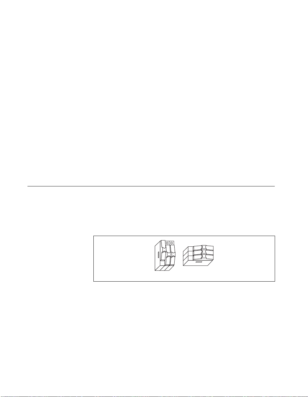
Before you connect your IMAQ D100100 cable to the IMAQ SCB-100
connector block, you must change the IMAQ SCB-100 switch settings to
the generic screw terminals switch configuration, as shown in Figure 1.
This setting change disconnects the IMAQ SCB-100 temperature sensor
and accessory grounds.
Figure 1.
IMAQ SCB-100 and D100100 Installation Guide 2
S1
S2
S3
S6S5S4
IMAQ SCB-100 Switch Settings for IMAQ
©
National Instruments Corporation
Page 3
IMAQ Quick Reference Label
A quick reference label is included to show switch configuration and define
screw terminal pinouts for your IMAQ digital device. Attach the quick
reference label to the connector block’s inside cover for quick reference.
Installation
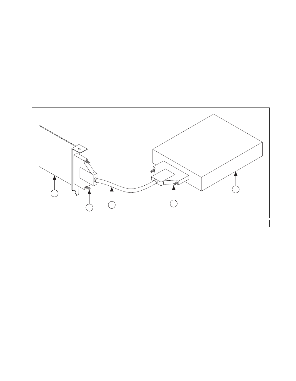
As shown in Figure 2, attach one end of the D100100 cable to your IMAQ
device and attach the other to the IMAQ SCB-100 connector block. Tighten
thumbscrews as necessary.
1
2
1 IMAQ Device 2Thumbscrews 3 IMAQ D100100 Cable 4 IMAQ SCB-100
3
Figure 2.
Connecting the D100100 Cable to Your IMAQ Device and IMAQ SCB-100
2
4
©
National Instruments Corporation 3 IMAQ SCB-100 and D100100 Installation Guide
Page 4

Signal Connections
The following warnings contain important safety information concerning
hazardous voltages and terminal blocks.
Warning
Warning
Warning
Avoid live circuits. To avoid electrical shock, do not remove equipment covers or
shields unless you are qualified to do so. If signal wires are connected to the IMAQ
SCB-100, dangerous voltages may exist even when the equipment is turned off.
Before removing the cover, disconnect the AC power or any live circuit from the
terminal block.
The chassis ground terminals on your IMAQ SCB-100 are for grounding
high-impedance sources such as a floating source (1 mA maximum). Do not use
these terminals as safety earth grounds.
Do not connect high voltages (≥≥42 Vrms). National Instruments is
NOT
liable for
any damages or injuries resulting from improper use or connection.
To connect the signal to the IMAQ SCB-100, perform the following steps:
1. Disconnect the 100-pin cable from the IMAQ SCB-100, if connected.
2. Remove the grounding screws on either side of the top cover with a
No. 1 Phillips-head screwdriver. Open the top cover.
3. Configure switches, as explained in the Switch Settings section in this
guide.
4. Adjust the strain-relief hardware.
• Loosen the strain-relief screws with a No. 2 Phillips-head
screwdriver and slide the signal wires through the front panel
strain-relief opening.
• If you are connecting multiple signals, remove the top strain-relief
bar.
5. Add insulation or padding if necessary .
6. Connect the wires to the screw terminals by stripping 1/4 in. of
insulation, inserting the wires into the green terminals, and tightening
the screws.
7. Reinstall strain-relief (if removed) and tighten the strain-relief screws.
8. Close the top cover.
9. Reinsert the grounding screws to ensure proper shielding.
10. Connect the terminal block to the 100-pin connector.
IMAQ SCB-100 and D100100 Installation Guide 4
©
National Instruments Corporation
Page 5

Removing the Board
You can remove the board from its housing to solder components into
place. To remove the board, perform the following steps:
1. Disconnect the 100-pin cable from the IMAQ SCB-100, if connected.
2. Remove the grounding screws on either side of the top cover with a
No. 1 Phillips-head screwdriver.
3. Open the top cover.
4. Loosen the strain-relief screws with a No. 2 Phillips-head screwdriver.
5. Remove the signal wires from the screw terminals.
6. Remove the board mount screws and 100-pin connector screws.
7. Tilt the board up and pull it out of the enclosure.
Figure 3 shows the IMAQ SCB-100 terminal block parts locator diagram.
©
National Instruments Corporation 5 IMAQ SCB-100 and D100100 Installation Guide
Page 6

4
3
5
2
1
10
11
6
7
8
9
1 Cold-Junction Compensation
Temperature Sensor (Not Used)
2 Product Name
3 Switches S4, S5, and S6
4 100-Pin I/O Connector
5 Signal Accessory Power LED
(Not Used)
6 Switches S1, S2, and S3
7 Serial Number
8 Assembly Number
Figure 3. IMAQ SCB-100 Terminal Block Parts Locator Diagram
IMAQ SCB-100 and D100100 Installation Guide 6
12
9 Screw Terminals
10 Breadboard Area
11 Board Mount Screws
12 Jumper Trace (cut to disconnect)
©
National Instruments Corporation
Page 7

Adding Components to the IMAQ SCB-100 Printed Circuit Board
Some applications may require you to make modifications to the printed
circuit board, usually in the form of adding components or cutting jumpers.
Follow these guidelines when modifying the IMAQ SCB-100 printed
circuit board:
• Use a low-wattage soldering iron (20 to 30 W) when soldering to the
board.
• Use vacuum-type tools to desolder on the IMAQ SCB-100. Use care
when desoldering to avoid damaging component pads.
• Use only rosin-core, electronic-grade solder. Acid-core solder can
damage the printed circuit board and components.
T o make signal modifications easier , jumper traces are located ne xt to each
analog screw terminal. These jumper traces can be cut to disconnect the
signal from the screw terminal. Refer to Figure 3 for more detail.
©
National Instruments Corporation 7 IMAQ SCB-100 and D100100 Installation Guide
Page 8

Specifications
This section lists the IMAQ SCB-100 specifications. These ratings are
typical at 25 °C unless otherwise stated.
General
Number of screw terminals.....................101 (includes one no-connect).
Physical
Box dimensions (including feet).............19.6 by 15.2 by 4.6 cm
I/O connectors.........................................One 100-pin male 0.050 series
Operating Environment
Component temperature .........................0 to 70 °C
Relative humidity ...................................5% to 90% noncondensing
All I/O signals are available at
screw terminals
(7.7 by 6.0 by 1.8 in.)
shielded D type connector
Storage Environment
Temperature............................................–55 to 125 °C
Relative humidity ...................................5% to 90% noncondensing
 Loading...