

Page 1

National Instruments IC-3173 Manual
Get Pricing & Availability at
ApexWaves.com
Call Today: 1-800-915-6216
Email: sales@apexwaves.com
https://www.apexwaves.com/modular-systems/national-instruments/industrial-controllers/IC-3173
Page 2

USER MANUAL
IC-317x
Industrial Controller with Reconfigurable I/O
This document describes the features of the National Instruments IC-317x and contains
information about mounting and operating the device.
Contents
IC-3171, IC-3172, and IC-3173................................................................................................1
About the IC-317x............................................................................................................ 1
Hardware Overview.......................................................................................................... 2
Mounting the IC-317x.....................................................................................................21
IC-3173 (IP67)........................................................................................................................ 27
About the IC-3173 (IP67)............................................................................................... 27
Hardware Overview........................................................................................................ 28
Mounting the IC-3173 (IP67)......................................................................................... 45
Software Options.....................................................................................................................48
IEEE 1588 Precision Time Protocol References.....................................................................49
BIOS Configuration and System Recovery............................................................................ 49
Entering BIOS Setup.......................................................................................................49
BIOS Setup Utility Keyboard Navigation...................................................................... 49
Main Setup Menu............................................................................................................50
Advanced Menu.............................................................................................................. 51
Boot Menu.......................................................................................................................53
Save & Exit Menu...........................................................................................................54
Restoring the NI Linux Real-Time Operating System....................................................55
Restoring the Windows Operating System..................................................................... 55
Where to Go Next................................................................................................................... 57
Resources for LabVIEW Users.......................................................................................57
Resources for Vision Builder AI Users...........................................................................57
Worldwide Support and Services............................................................................................57
IC-3171, IC-3172, and IC-3173
The following information applies to the IC-3171, IC-3172, and IC-3173.
About the IC-317x
The IC-317x is a high-performance, small, fanless embedded computer designed for rugged
industrial applications. The IC-317x also provides multiple digital input/output (I/O) options
for communicating with external devices.
Page 3
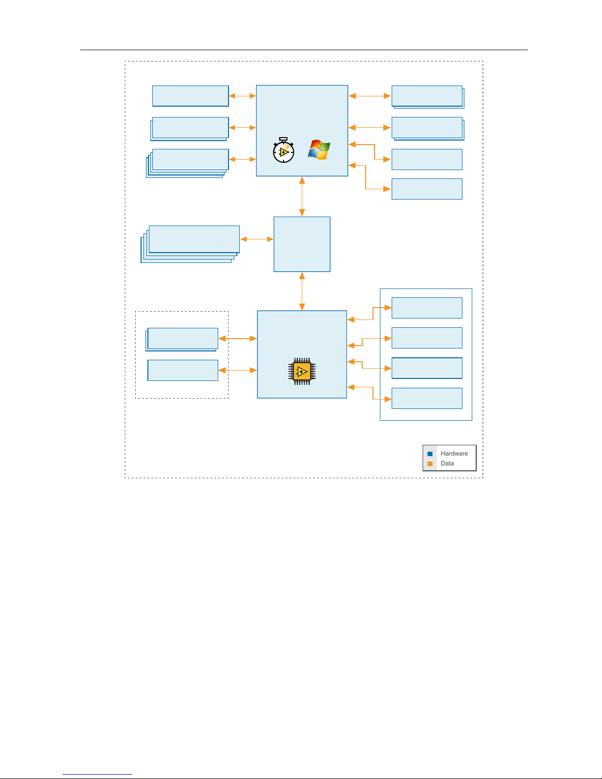
Figure 1. IC-317x Block Diagram
Intel Dual-Core Processor
i7-5650U, i5-5350U,
or Celeron 3765U
Xilinx
Kintex-7 FPGA
7K160T
IC-317x
Hardware
Data
x2 DisplayPort
8/4 GB DDR3L
Memory
64/32/4 GB
Solid-state Drive
RJ50 Serial Port
RS-232/422/485
x8 TTL I/O
x2 RS-422 I/O
x8 Isolated
Outputs
x8 Isolated
Inputs
RJ45 Primary Gigabit
Ethernet Port
x2 USB 3.0
Host Ports
x4 USB 2.0
Host Ports
x4 RJ45 Gigabit
Ethernet Ports with PoE
2 GB DDR3L
Memory
4.5 MB
QDR-II+ SRAM
PCI Express
Switch
44-pin D-sub
IC-3173 Only
PCIe
Gen 2
x4
PCIe
Gen 2
x4
Hardware Overview
The IC-317x front panel consists of four Gigabit Ethernet ports with Power over Ethernet
(PoE), one RS-232/RS-485 serial port, one standard Gigabit Ethernet Port, two USB 3.0 ports,
four USB 2.0 ports, and two DisplayPort connectors.
The IC-317x front panel also includes LEDs for communicating system status and a 44-pin
Digital I/O port. The Digital I/O port offers 8 isolated inputs, 8 isolated outputs, 2 bidirectional
differential I/O (RS-422) or single-ended input lines that can be used with a quadrature
encoder, and 8 bidirectional TTL lines.
2 | ni.com | IC-317x User Manual
Page 4
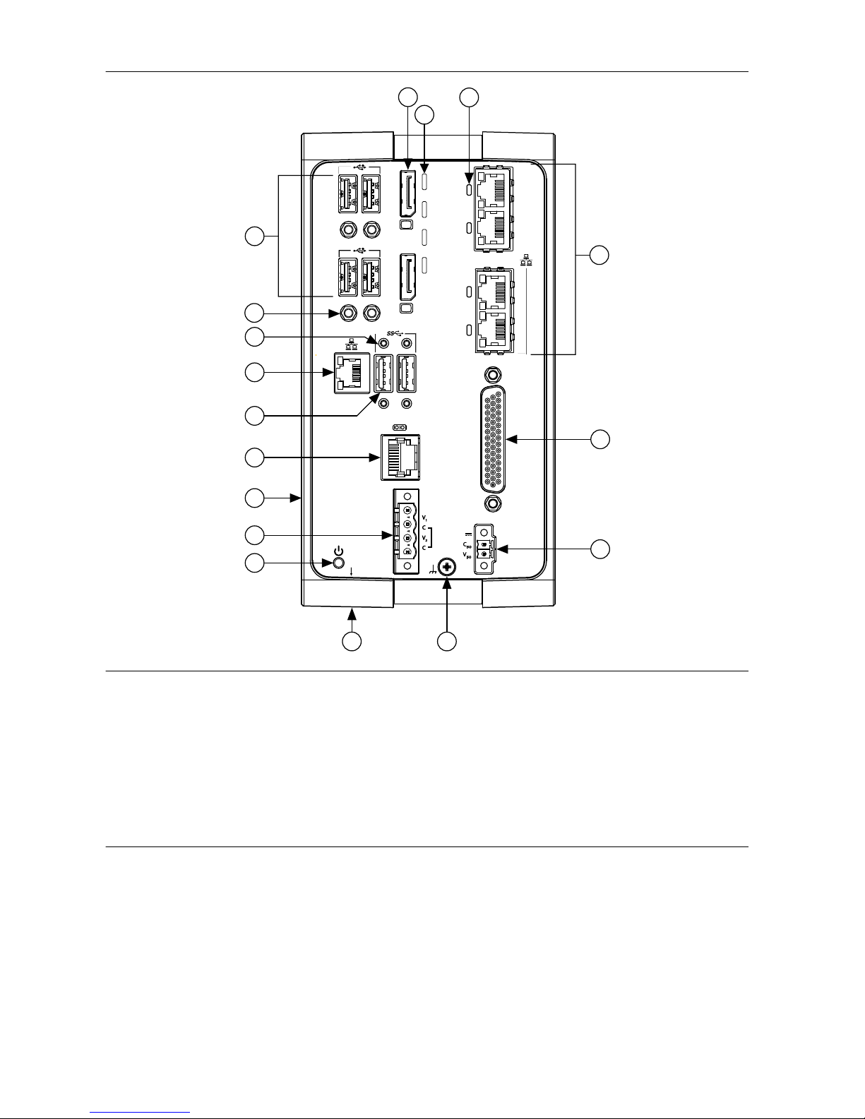
Figure 2. IC-317x Front Panel
POWER
PoE1
PoE2
PoE3
PoE4
DIO
STATUS
USER1
DP
DP
USER FPGA1
ACT/
LINK
10/100/
1000
17
4
14
5
6
7
1
12
13
9
10
11
16
15
8
2
3
1. DisplayPort Connectors
2. LED Indicators
3. Power over Ethernet (PoE) LED Indicators
4. Gigabit Ethernet Ports with PoE
5. 44-pin Digital I/O Connector
6. Isolated Power Input Connector
7. Chassis Grounding Screw
8. Reset Button (not pictured)
9. Power Button
10. System Power Connector
11. User-Accessible Battery Compartment (not
pictured)
12. RS-232/RS-485 Serial Port
13. USB 3.0 Ports
14. Primary Gigabit Ethernet Port
15. Retention Mounts for USB 3.0 Ports
16. Retention Mounts for USB 2.0 Ports
17. USB 2.0 Ports
Connector Pinouts
The IC-317x provides the following connectors.
DisplayPort
Use the DisplayPort connectors to connect one or more monitors to implement a local HMI for
your controller. You can develop a single real-time VI to use for both your user interface and
system logic. For more information, refer to the Using the Embedded UI to Access RT Target
IC-317x User Manual | © National Instruments | 3
Page 5
VIs topic in the LabVIEW Help. For up-to-date information about supported NI cables and
accessories, refer to the pricing section of the product page at ni.com.
Use an appropriate adapter cable to connect a DisplayPort connector to a VGA or DVI
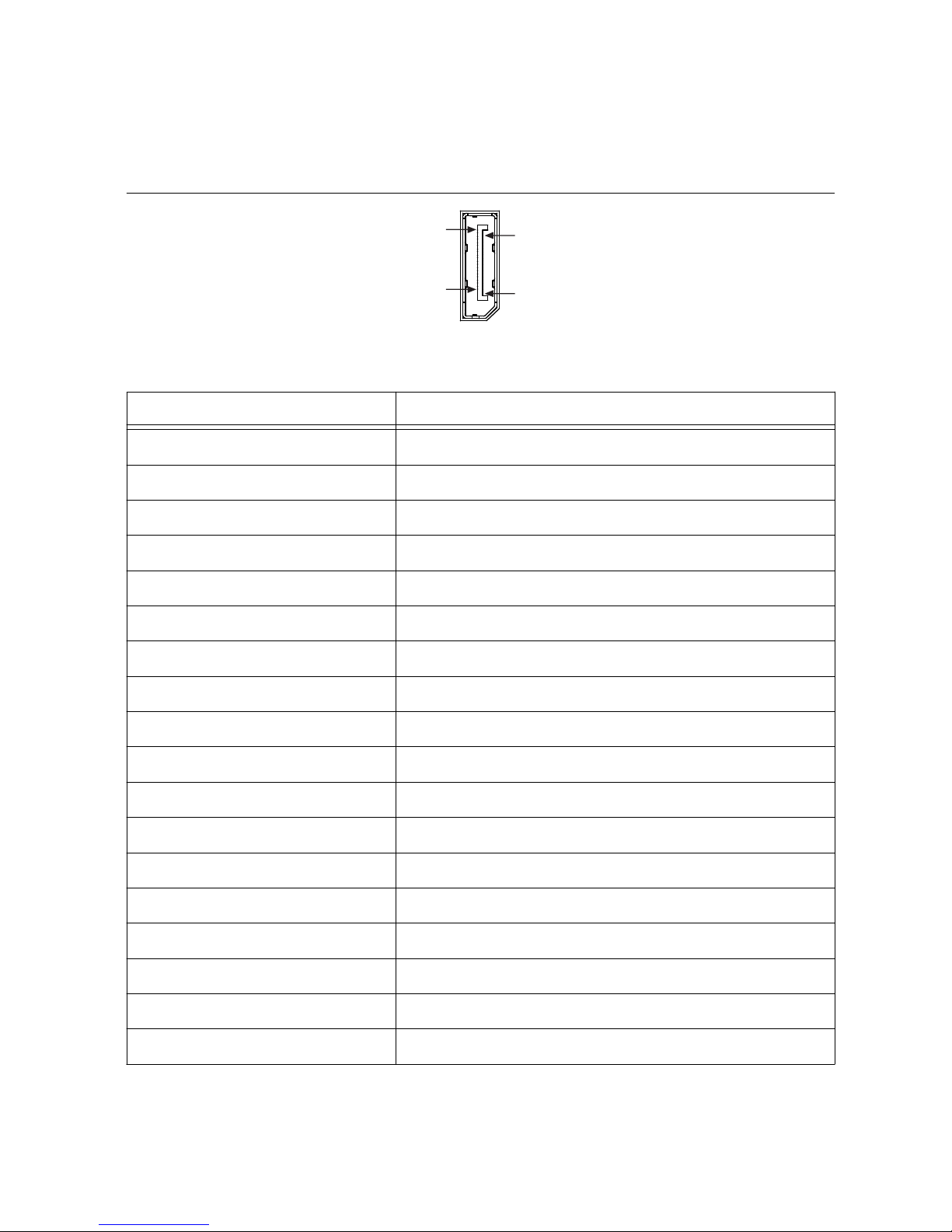
connector. The following figure lists the DisplayPort pins and signals.
Figure 3. DisplayPort Connector Pin Locations (IP20)
1
19
20
2
Table 1. DisplayPort Connector Pin Descriptions
Pin Signal Name
1 ML_Lane0(p)
2 GND
3 ML_Lane0(n)
4 ML_Lane1(p)
5 GND
6 ML_Lane1(n)
7 ML_Lane2(p)
8 GND
9 ML_Lane2(n)
10 ML_Lane3(p)
11 GND
12 ML_Lane3(n)
13 CONFIG1
14 CONFIG2
15 AUX CH (p)
16 GND
17 AUX CH (n)
18 Hot Plug Detect
4 | ni.com | IC-317x User Manual
Page 6
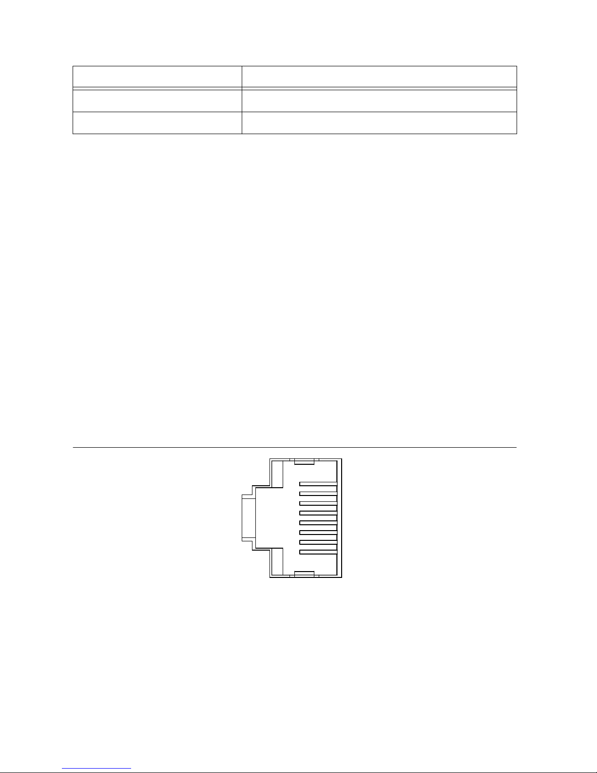
Table 1. DisplayPort Connector Pin Descriptions (Continued)
Pin Signal Name
19 Return
20 DP_PWR
Ethernet Ports
The IC-317x provides one standard Gigabit Ethernet network port and four Gigabit Ethernet
ports with Power over Ethernet (PoE). The Ethernet ports provide a connection between the
IC-317x, a network, and other Ethernet devices. The IC-317x automatically detects the speed
of the connection and configures itself accordingly.
If a PoE-capable device is plugged into an Ethernet port with PoE, the IC-317x automatically
supplies power to the device. When the IC-317x supplies PoE, the LED that corresponds to the
port illuminates. When you unplug a PoE device, PoE is automatically disabled. You can use
non-PoE Ethernet devices with PoE-enabled Gigabit Ethernet ports.
A CAT 5e or CAT 6 1000Base-T Ethernet cable is required to achieve 1,000 Mbps (Gigabit)
Ethernet performance. CAT 5 Ethernet cables are not guaranteed to meet the necessary
requirements. While CAT 5 cables may appear to work at 1,000 Mbps, CAT 5 cables can cause
bit errors, resulting in degraded or unreliable network performance.
(Windows only) The network Ethernet port provides Wake-on-LAN functionality from the
power off state when associated with the Intel® driver. Wake-on-LAN must be enabled in the
Power Management tab of the Intel I210 Gigabit Network Connection Properties dialog for the
primary Ethernet port in Device Manager. The NI GigE Vision driver (NI-GEV) does not
support Wake-on-LAN. The Ethernet ports with PoE do not support Wake-on-LAN.
Figure 4. Ethernet Port Pin Locations (IP20)
1
2
3
4
5
6
7
8
IC-317x User Manual | © National Instruments | 5
Page 7
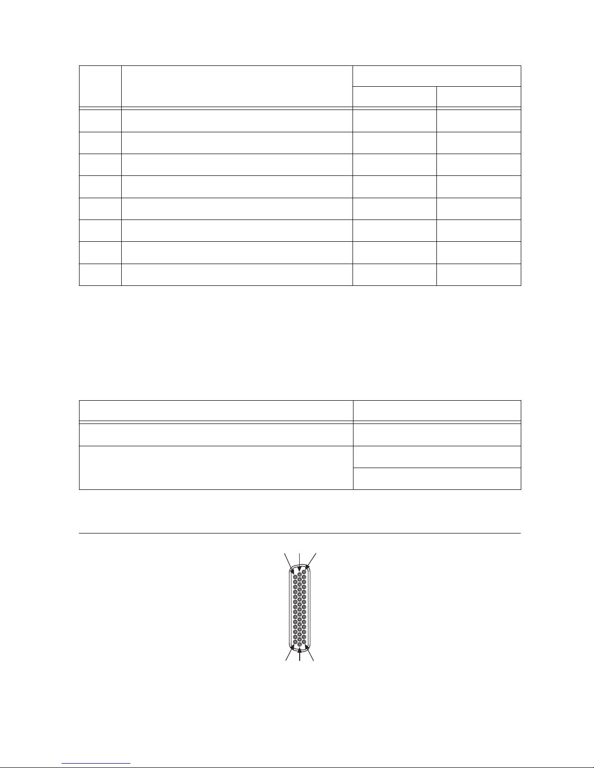
Table 2. Ethernet Port Pin Descriptions
Pin Fast Ethernet (100 Mbps) Gigabit Ethernet
MDI MDI-X
1 TX+ BI_DA+ BI_DB+
2 TX- BI_DA- BI_DB-
3 RX+ BI_DB+ BI_DA+
4 No Connect BI_DC+ BI_DD-
5 No Connect BI_DC- BI_DD-
6 RX- BI_DB- BI_DA-
7 No Connect BI_DD+ BI_DC+
8 No Connect BI_DD- BI_DC-
Digital I/O
The 44-pin Digital I/O port on the IC-317x offers 8 isolated inputs, 8 isolated outputs, 2
bidirectional differential inputs (RS-422) or single-ended input lines that can be used with a
quadrature encoder, and 8 bidirectional TTL lines. The Digital I/O port can be connected to
any appropriate shielded device or connector block using a shielded cable.
NI recommends the following digital I/O cables for the IC-317x.
Cable
Part Number
44-pin D-sub male to pigtail cable 156083-03 for 3 meter cable
44-pin D-sub male to 44-position D-sub female cable 156084-03 for 3 meter cable
156084-0R5 for 0.5 meter cable
Refer to the following image and table for pin locations and descriptions.
Figure 5. 44-pin Digital I/O Connector Pin Locations (IP20)
15
30
44
1
16
31
6 | ni.com | IC-317x User Manual
Page 8

Table 3. Digital I/O Pin Descriptions
Pin Number Signal Description
1 Diff 0+ Bidirectional RS-422 I/O (positive side), or quadrature encoder
phase A+
2 GND Digital ground reference for TTL and differential I/O
3 TTL 0 Bidirectional TTL I/O
4 TTL 1 Bidirectional TTL I/O
5 GND Digital ground reference for TTL and differential I/O
6 TTL 2 Bidirectional TTL I/O
7 TTL 3 Bidirectional TTL I/O
8 GND Digital ground reference for TTL and differential I/O
9 Diff 1+ Bidirectional RS-422 I/O (positive side), or quadrature encoder
phase B+
10 V
ISO
Isolated power voltage reference output
11 C
ISO
Common ground reference for isolated inputs and outputs
12 Iso Out 0 General purpose isolated input
13 Iso Out 1 General purpose isolated input
14 C
ISO
Common ground reference for isolated inputs and outputs
15 Iso Out 4 General purpose isolated output
16 Diff 0- Bidirectional RS-422 I/O (negative side), or quadrature encoder
phase A-
17 GND Digital ground reference for TTL and differential I/O
18 TTL 4 Bidirectional TTL I/O
19 TTL 5 Bidirectional TTL I/O
20 GND Digital ground reference for TTL and differential I/O
21 TTL 6 Bidirectional TTL I/O
22 TTL 7 Bidirectional TTL I/O
23 GND Digital ground reference for TTL and differential I/O
24 Diff 1- Bidirectional RS-422 I/O (negative side), or quadrature encoder
phase B-
25 V
ISO
Isolated power voltage reference output
IC-317x User Manual | © National Instruments | 7
Page 9

Table 3. Digital I/O Pin Descriptions (Continued)
Pin Number Signal Description
26 C
ISO
Common ground reference for isolated inputs and outputs
27 Iso Out 2 General purpose isolated output
28 Iso Out 3 General purpose isolated output
29 C
ISO
Common ground reference for isolated inputs and outputs
30 Iso Out 5 General purpose isolated output
31 Iso In 0 General purpose isolated input
32 iso In 1 General purpose isolated input
33 C
ISO
Common ground reference for isolated inputs and outputs
34 Iso In 2 General purpose isolated input
35 Iso In 3 General purpose isolated input
36 C
ISO
Common ground reference for isolated inputs and outputs
37 Iso In 4 General purpose isolated input
38 Iso In 5 General purpose isolated input
39 C
ISO
Common ground reference for isolated inputs and outputs
40 Iso In 6 General purpose isolated input
41 Iso In 7 General purpose isolated input
42 C
ISO
Common ground reference for isolated inputs and outputs
43 Iso Out 6 General purpose isolated output
44 Iso Out 7 General purpose isolated output
Wiring an Isolated Input
You can wire an isolated input to a sourcing output device.
8 | ni.com | IC-317x User Manual
Page 10
Caution Do not allow the voltage on the isolated inputs to exceed 30 VDC. Doing
so will damage the IC-317x.
Figure 6. Connecting an Isolated Input to a Sourcing Output Device
V
REF
C
ISO
Industrial Controller
Input
Sourcing
Output
Device
Current
Limiter
Power Supply
+
–
Wiring an Isolated Output
The digital isolated output circuits source current to external loads.
When an inductive load, such as a relay or solenoid, is connected to an output, a large counterelectromotive force may occur at switching time due to energy stored in the inductive load.
This flyback voltage can damage the outputs and the power supply.
To limit flyback voltages at the inductive load, install a flyback diode across the load. Mount
the flyback diode as close to the load as possible. Use this protection method if you connect
any of the isolated outputs on the IC-317x to an inductive load.
The following image shows an example of an isolated output wired to an external load with a
flyback diode installed across the load.
IC-317x User Manual | © National Instruments | 9
Page 11
Caution Do not draw more than 35 mA from each isolated output when V
ISO
is
5 V. Do not draw more than 80 mA from each isolated output when V
ISO
is 24 V.
Figure 7. Connecting an Isolated Output to an External Load
Digital Output
External Flyback
Diode for
Inductive Loads
V
ISO
C
ISO
V
CC
Industrial Controller
Load
Overcurrent
Protection Circuit
Connecting to Differential I/O
The IC-317x accepts differential (RS-422) line driver inputs. Each of the two differential I/O
can be configured as an output. Use shielded cables for all applications. Unshielded cables are
more susceptible to noise and can corrupt signals.
10 | ni.com | IC-317x User Manual
Page 12
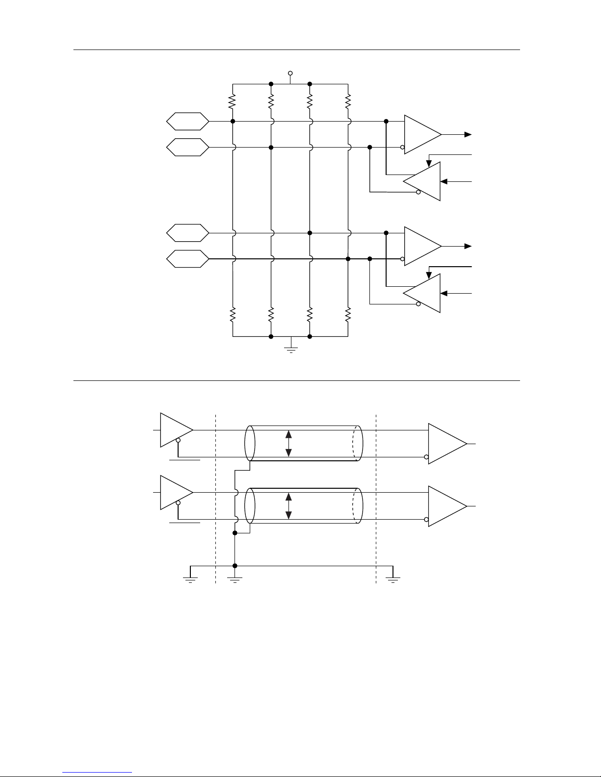
Figure 8. Quadrature Encoder/RS-422 Input/Output Circuit
+
–
Diff I/O 0–
Diff I/O 0+
Diff I/O 1–
Diff I/O 1+
+3.3 V
+
–
10 kΩ 10 kΩ 10 kΩ 10 kΩ
EN
EN
7.5 kΩ 7.5 kΩ 7.5 kΩ
7.5 kΩ
Figure 9. Connecting Differential Line Drivers
Diff In 0+
Diff In 0–
Phase A
Phase A
Diff In 1+
Diff In 1–
Phase B
Phase B
External Device Industrial Controller
Twisted Pair
Twisted Pair
+
–
+
–
IC-317x User Manual | © National Instruments | 11
Page 13
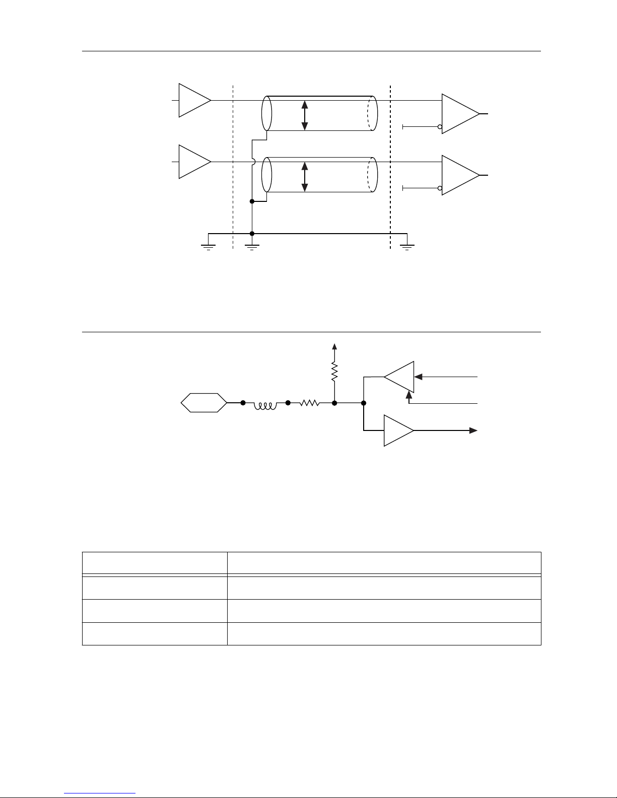
Figure 10. Connecting Single-Ended Line Drivers
Diff In 0+
Diff In 0–
Phase A
Twisted Pair
Twisted Pair
Diff In 1+
Diff In 1–
Phase B
External Device Industrial Controller
+
–
+
–
TTL I/O
The following image shows the circuit for a bidirectional TTL I/O.
Figure 11. TTL Input/Output Circuit
100 Ω
TTL_OUT
TTL_OE
TTL_IN
10 kΩ
FB
TTL I/O
Power Input Connectors
The IC-317x requires a power supply to power the system and, if you want to use the isolated
outputs, a power supply to power the isolated outputs.
Table 4. System Power Connector Terminals
Terminal Description
V
1
System power (9-30 VDC)
C Common signal
V
2
System power (9-30 VDC)
12 | ni.com | IC-317x User Manual
Page 14
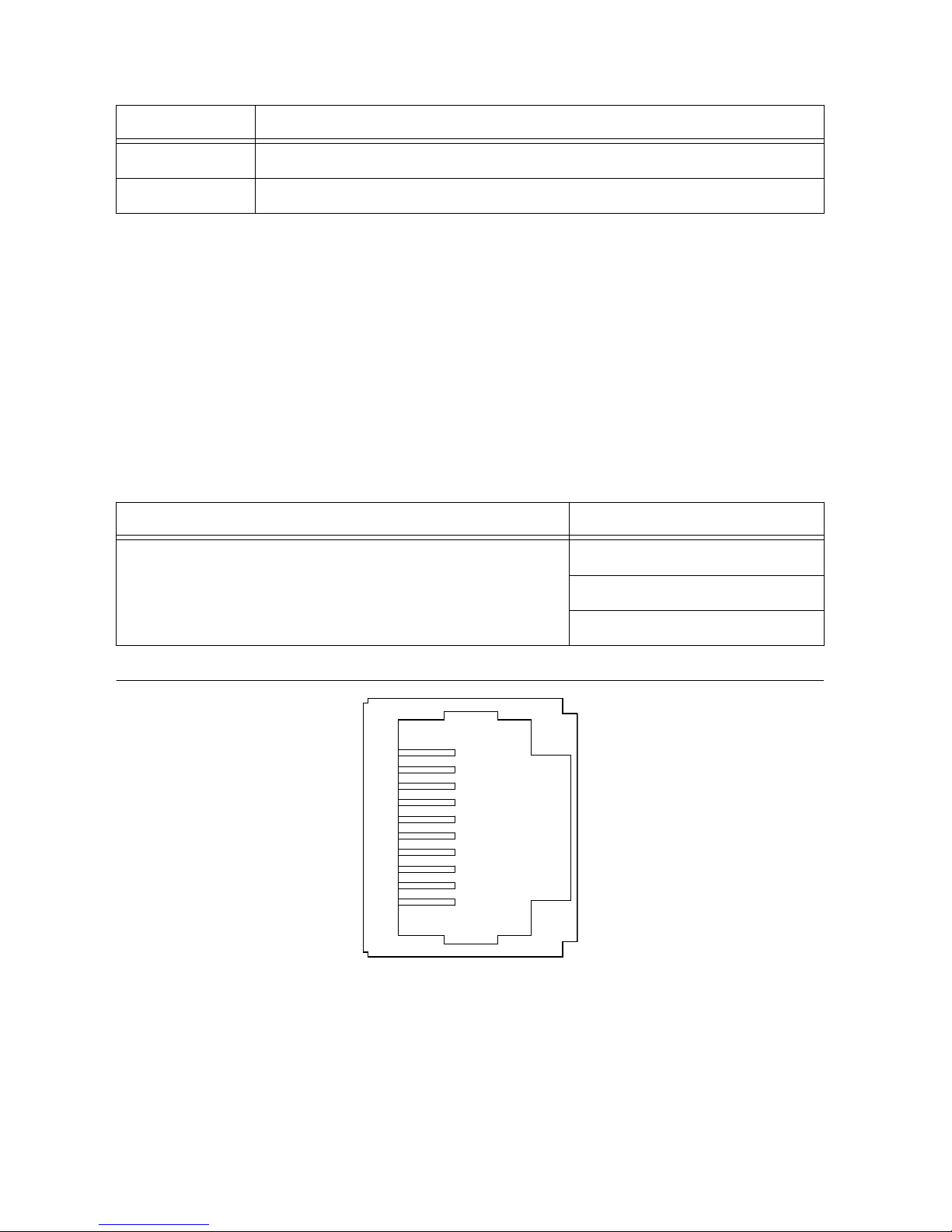
Table 5. Isolated Power Connector Terminals
Terminal Description
C
ISO
Isolated common signal
V
ISO
Power for isolated outputs (4.5 to 30 VDC)
Chassis Grounding Screw
Use the grounding screw to connect the chassis to earth ground. An earth ground connection is
optional.
RS-485/422/232 Serial Port
The IC-317x has a single serial port that can operate in either RS-485/422 mode or RS-232
mode. Set the serial port mode in the BIOS setup utility.
The serial port is a 10-position RJ50 modular jack, which can connect to serial devices, such
as PLCs, scanners, and lighting devices.
NI recommends the following serial cables for the IC-317x.
Cable Part Number
RJ50 10-position modular plug to DB-9 serial cable 182845-01 for 1 meter cable
182845-02 for 2 meter cable
182845-03 for 3 meter cable
Figure 12. RS-485/422/232 Serial Port Pin Locations (IP20)
3
4
5
6
7
8
9
10
1
2
IC-317x User Manual | © National Instruments | 13
Page 15
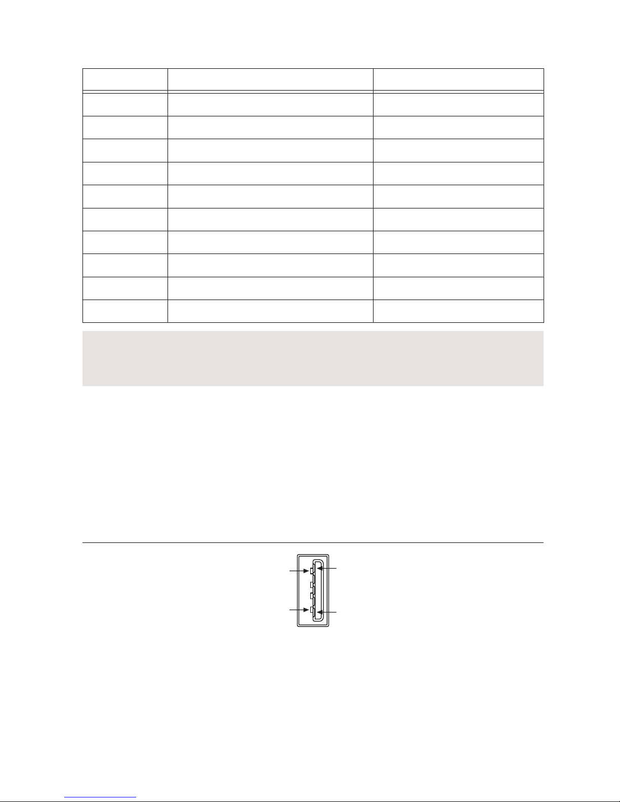
Table 6. RS-485/422/232 Serial Port Pin Descriptions
Pin RS-485/422 Mode RS-232 Mode
1 No Connect No Connect
2 TXD- Unused
3 TXD+ Unused
4 No Connect No Connect
5 No Connect No Connect
6 RXD- GND
7 RXD+ Unused
8 Unused TXD
9 Unused RXD
10 GND Unused
Related Information
Serial Port Configuration Submenu on page 53
Serial Port Configuration Submenu on page 53
USB 3.0 Ports
The USB ports support common USB peripheral devices such as USB flash drives, USB hard
drives, USB-to-IDE adapters, keyboards, mice, and USB cameras.
LabVIEW Real-Time usually maps USB mass-storage devices to the /U, /V, /W, or /X drive,
starting with the /U drive if it is available. Refer to the LabVIEW Help for more information.
LabVIEW Real-Time usually maps USB mass-storage devices to the /U, /V, /W, or /X drive,
starting with the /U drive if it is available. Refer to the LabVIEW Help for more information.
Figure 13. USB 3.0 Port Pin Locations (IP20)
1
4
9
5
14 | ni.com | IC-317x User Manual
Page 16
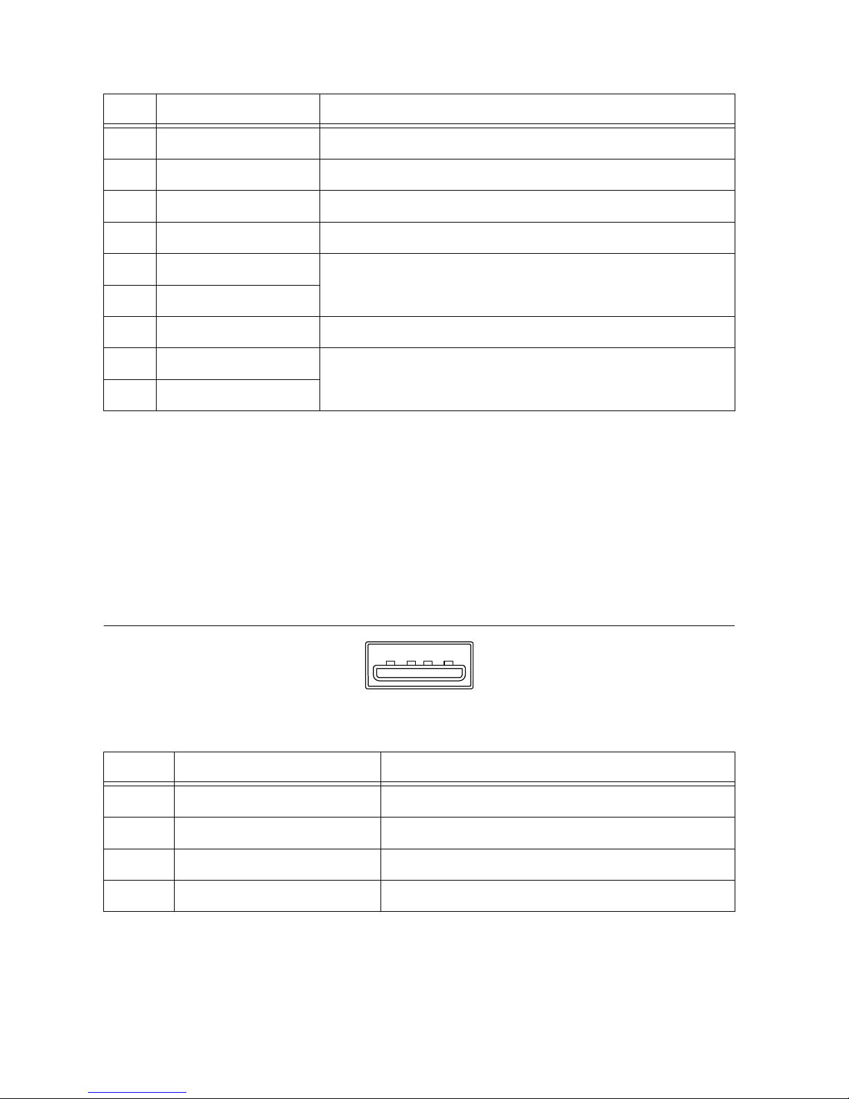
Table 7. USB 3.0 Port Pin Descriptions
Pin Signal Name Signal Description
1 VBUS Cable Power (+5 VDC)
2 D- USB Data -
3 D+ USB Data +
4 GND Ground for power return
5 StdA_SSRX- SuperSpeed receiver differential pair
6 StdA_SSRX+
7 GND_DRAIN Ground for signal return
8 StdA_SSTX- SuperSpeed transmitter differential pair
9 StdA_SSTX+
USB 2.0 Ports
The USB ports support common USB peripheral devices such as USB flash drives, USB hard
drives, USB-to-IDE adapters, keyboards, mice, and USB cameras.
LabVIEW Real-Time usually maps USB mass-storage devices to the /U, /V, /W, or /X drive,
starting with the /U drive if it is available. Refer to the LabVIEW Help for more information.
LabVIEW Real-Time usually maps USB mass-storage devices to the /U, /V, /W, or /X drive,
starting with the /U drive if it is available. Refer to the LabVIEW Help for more information.
Figure 14. USB 2.0 Pin Locations (IP20)
4
3
2
1
Table 8. USB 2.0 Port Pin Descriptions
Pin Signal Name Signal Description
1 VBUS Cable Power (+5 VDC)
2 D- USB Data -
3 D+ USB Data +
4 GND Ground for power return
LED Indicators
The LED indicators are located on the front panel of the device. The IC-317x provides the
following LED indicators.
IC-317x User Manual | © National Instruments | 15
Page 17

POWER LED
The following table lists the POWER LED indications.
Table 9. POWER LED Indications
LED Color LED Pattern Indication
Green Solid The IC-317x is powered from the V1 input.
Yellow Solid The IC-317x is powered from the V2 input.
— Off The IC-317x is powered off.
STATUS LED
The following table describes the STATUS LED indications.
16 | ni.com | IC-317x User Manual
Page 18
Table 10. STATUS LED Indications
LED Color LED State Indication
Yellow OFF The IC-317x initialized successfully and is ready for use.
2 blinks (RT only) The device has automatically booted into safe
mode. This occurs when there is no software installed, which
is the out-of-box state, or the device has detected an error in
its software. Reinstall software on the IC-317x.
3 blinks (RT only) The IC-317x has booted into safe mode.
4 blinks (RT only) The IC-317x has experienced two consecutive
software exceptions. The IC-317x automatically restarts after
an exception. After the second exception, the IC-317x
remains in the exception state, alerting you to resolve the
problem. Reinstall software on the IC-317x or contact
National Instruments.
Continuous
blink
(RT only) The IC-317x has not booted into NI Linux RealTime. The controller either booted into an unsupported
operating system, was interrupted during the boot process, or
detected an unrecoverable software error.
ON (RT only) The IC-317x is booting up.
(Windows only) An internal drive is being accessed.
Red Continuous
blink
This indicates a hardware error. An internal power supply has
failed. Check front-panel I/O connections for shorts. Remove
any shorts and cycle power to the IC-317x. If the problem
persists, contact National Instruments.
Related Information
Safe Mode on page 19
Safe Mode on page 19
User LEDs
You can define the USER1 and USER FPGA1 LEDs to meet the needs of your application.
The following table describes the USER1 and USER FPGA1 LED indicators.
IC-317x User Manual | © National Instruments | 17
Page 19

Table 11. User LEDs
LED LED Color Indication
USER1 Green/Yellow Use LabVIEW Real-Time to define the USER1 LED with the
RT LEDs VI. For more information about the RT LEDs VI,
refer to the LabVIEW Help.
USER
FPGA1
Green/Yellow Use the LabVIEW FPGA Module and NI Industrial Controller
Device Drivers software to define the USER FPGA1 LED.
Use the USER FPGA1 LED to help debug your application or
display application status. Refer to the LabVIEW Help for
information about programming this LED.
PoE LEDs
The PoE (Power over Ethernet) LEDs are located to the left of the PoE ports. The following
table describes the PoE LED indications:
Table 12. PoE LED Indications
PoE LED State Indication
OFF The corresponding PoE port is not supplying power.
ON The corresponding PoE port is powering the connected device.
Ethernet LEDs
The Gigabit Ethernet ports have the following LEDs.
Figure 15. LEDs for the Gigabit Ethernet Ports
1
2
1. Speed LED
2. Activity/Link LED
Table 13. Ethernet LED Indications
LED Status Indication
Speed
OFF No link, or 10 Mbps link
Green 100 Mbps link
Amber 1,000 Mbps link
18 | ni.com | IC-317x User Manual
Page 20

Table 13. Ethernet LED Indications (Continued)
LED Status Indication
Activity/Link
OFF No link has been established
Solid A link has been negotiated
Blinking Activity on the link
Using the RESET Button
Pressing the RESET button resets the processor in the same manner as cycling power. You can
also use the RESET button to troubleshoot network connectivity.
The RESET button is located on the bottom of the controller.
1. Hold the RESET button for 5 seconds, and then release it to boot the IC-317x into safe
mode and enable Console Out.
2. After booting the controller into safe mode, hold the RESET button again for 5 seconds to
enable IP reset, which resets the network adapter to its default configuration.
Safe Mode
When you boot the IC-317x into safe mode, it launches only the services necessary for
updating its configuration and installing software. To resume normal operations, press the
RESET button for less than 5 seconds.
IP Reset
Use IP reset to reset the TCP/IP settings when moving the system from one subnet to another
or when the current TCP/IP settings are invalid.
When the IC-317x is in the IP reset state, the IP address of the network port resets to DHCP or
a link-local address. You can then set up a new network configuration for the IC-317x from a
development machine on the same subnet, or you can connect the IC-317x directly to the
development computer.
Note By default, the target automatically attempts to connect to the network using
DHCP. If the target is unable to initiate a DHCP connection, the target connects to
the network with a link-local IP address (169.254.x.x).
Replacing the Battery
The IC-317x contains a user-replaceable battery. The battery compartment is located on the
left side of the device as you look at the device from the front. Take the following steps to
replace the battery:
Caution Before removing the battery cover, disconnect all power connectors and
I/O cables from the device. To prevent damage from electrostatic discharge (ESD),
ground the unit and yourself by using a grounding strap or touching a grounded
object, such as a computer chassis.
IC-317x User Manual | © National Instruments | 19
Page 21

1. Use a Phillips head screwdriver to remove the two screws holding the battery cover plate.
Remove the plate, then remove battery from the device.
2. Insert a new battery in the device. Ensure the positive terminal of the battery faces
outward. Refer to the device specifications for the required battery type.
3. Replace the battery cover plate.
Replacing the battery resets the BIOS settings to their default values.
Increasing the Battery Life
When storing the controller, you can disconnect the battery to deactivate the real-time clock
and reset the BIOS settings to their default values. Take the following steps to disconnect the
battery:
Caution Before removing the battery cover, disconnect all power connectors and
I/O cables from the device. To prevent damage from electrostatic discharge (ESD),
ground the unit and yourself by using a grounding strap or touching a grounded
object, such as a computer chassis.
1. Use a Phillips head screwdriver to remove the two screws holding the battery cover plate.
Remove the plate.
2. Locate the BATTERY CONNECT switch above the battery and move the switch toward
the front panel of the device. The battery is now disconnected from the device.
3. Replace the battery cover plate.
20 | ni.com | IC-317x User Manual
Page 22

Figure 16. Side of Device with Removed Battery Cover Plate and BATTERY
CONNECT Switch in Disconnected Position
Mounting the IC-317x
This section provides information for creating a custom mount for the IC-317x. If you do not
want to create a custom mount, a panel mount kit for the IC-317x is available from National
Instruments (part number 784791-01).
Caution Do not position the IC-317x with the heat sinks resting on any surface.
Doing so may cause the IC-317x device to overheat. Refer to the IC-317x
Specifications for temperature specifications.
To obtain the maximum allowable ambient temperature, you must mount the IC-317x
vertically. The following figures provide dimensional drawings and clearance information for
the IC-317x.
IC-317x User Manual | © National Instruments | 21
Page 23

Figure 17. Front View Dimensions
POWER
PoE1
PoE2
PoE3
PoE4
DIO
STATUS
USER1
DP
DP
USER FPGA1
ACT/
LINK
10/100/
1000
SYS PWR IN
150
W MAX
ISO PWR IN
5-24 V
RESET
9-30 V
21.35 mm
(0.84 in.)
46.94 mm
(1.85 in.)
46.17 mm
(1.58 in.)
42.60 mm
(1.68 in.)
28.19 mm
(1.11 in.)
22.72 mm
(0.89 in.)
27.94 mm
(1.10 in.)
30.75 mm
(1.21 in.)
26.95 mm
(1.06 in.)
35.18 mm
(1.39 in.)
30.48 mm
(1.20 in.)
11.45 mm
(0.45 in.)
22.7 mm
(0.89 in.)
8.5 mm
(0.34 in.)
31.58 mm
(1.24 in.)
16.97 mm
(0.67 in.)
13.45 mm
(0.53 in.)
22.21 mm
(0.87 in.)
22.21 mm
(0.87 in.)
2.58 mm
(0.10 in.)
28.02 mm
(1.10 in.)
3.27 mm
(0.129 in.)
36.12mm
(1.42 in.)
22 | ni.com | IC-317x User Manual
Page 24

Figure 18. Side View Dimensions
15.08 mm
(0.20 in.)
173.99 mm
(6.85 in.)
4.23 mm
(0.17 in.)
167.63 mm
(6.60 in.)
176.94 mm
(6.97 in.)
IC-317x User Manual | © National Instruments | 23
Page 25

Figure 19. Rear View Dimensions
132.08 mm
(5.20 in.)
18.03 mm
(0.71 in.)
23.88 mm
(0.94 in.)
33.15 mm
(1.31 in.)
22.29 mm
(0.88 in.)
37.27 mm
(1.47 in.)
92.71 mm
(3.65 in.)
4x 6-32
7.00 mm (0.28 in.)
Securing the IC-317x to a Mount
1. Align the screw holes of the mounting bracket with the four holes on the back of the
IC-317x.
2. Insert four 6-32 screws and tighten them 0.28 N · m (3.5 lb · in) until they are secure.
Ensure the heads of the screws are flush with the mounting bracket.
24 | ni.com | IC-317x User Manual
Page 26

Figure 20. Securing a Mounting Bracket to the Device
IC-317x User Manual | © National Instruments | 25
Page 27

Figure 21. Mounting Bracket Dimensions
157.48 mm
(6.20 in.)
16.26 mm
(0.64 in.)
170.18 mm
(6.70 in.)
27.11 mm
(1.07 in.)
72.39 mm
(2.85 in.)
91.44 mm
(3.6 in.)
3.18 mm
(0.13 in.)
Clearance Requirements
The IC-317x installation must meet the following space and cabling clearance requirements
for optimum cooling:
• Allow 101.6 mm (4.0 in.) on the top and bottom of the IC-317x for air circulation.
• Allow 50.8 mm (2.0 in.) on the sides of the IC-317x for air circulation.
• Allow enough space in front of the IC-317x to connect cables.
26 | ni.com | IC-317x User Manual
Page 28

Figure 22. Clearance Requirements for the IC-317x
101.6 mm
(4.00 in.)
101.6 mm
(4.00 in.)
50.8 mm
(2.00 in.)
50.8 mm
(2.00 in.)
IC-3173 (IP67)
The following information applies to the IC-3173 (IP67).
About the IC-3173 (IP67)
The IC-3173 (IP67) is a high-performance, small, fanless embedded computer designed for
rugged industrial applications. The IC-3173 (IP67) also provides multiple digital input/output
(I/O) options for communicating with external devices.
IC-317x User Manual | © National Instruments | 27
Page 29

Figure 23. IC-3173 (IP67) Block Diagram
Intel Dual-Core Processor
i7-5650U, i5-5350U,
or Celeron 3765U
Xilinx
Kintex-7 FPGA
7K160T
IC-317x
Hardware
Data
x2 DisplayPort
8/4 GB DDR3L
Memo ry
64/32/ 4 GB
Solid-stat e Drive
Serial Port
RS-232/422/485
x8 TTL I/O
x2 RS-422 I/O
x8 Isolated
Outputs
x8 Isolated
Inputs
RJ45 Primary Gigabit
Ethernet Port
x2 USB 3.0
Host Ports
x1 USB 2.0
Host Ports
x4 Gigabit
Ethernet Ports with PoE
2 GB DDR3L
Memory
4.5 MB
QDR-II+ SRAM
PCI Express
Swit ch
x3 DIO Connectors
IC-3173 Only
PCIe
Gen 2
x4
PCIe
Gen 2
x4
Hardware Overview
The IC-3173 (IP67) front panel consists of four Gigabit Ethernet ports with Power over
Ethernet (PoE), one RS-232/RS-485 serial port, one system Gigabit Ethernet Port, two USB
3.0 ports, one USB 2.0 port, and two DisplayPort connectors.
The IC-3173 (IP67) front panel also includes LEDs for communicating system status and three
17-pin Digital I/O ports. The Digital I/O ports offer 8 isolated inputs, 8 isolated outputs, 2
bidirectional differential I/O (RS-422) or single-ended input lines that can be used with a
quadrature encoder, and 8 bidirectional TTL lines.
28 | ni.com | IC-317x User Manual
Page 30

Figure 24. IC-3173 (IP67) Front Panel
IC-3173
IP67 Industrial Controller
ISO PWR IN
5-24V
CONNECTOR 2
CONNECTOR 1
SYS PWR IN
9-30V
150W MAX
RESET
CONNECTOR 0
POWER STATUS
SS
DP
DIGITAL I/O
SS
PoE 4
PoE 2PoE 1
PoE 3
SYNC
8
8
8
7
7
7
7
1
2
3
5
1
4
10
6
3
9
1. USB 3.0 Ports
2. USB 2.0 Port
3. DisplayPort Connectors
4. System Gigabit Ethernet Port
5. RS-232/RS-485 Serial Port
6. System Power Connector
7. Gigabit Ethernet Ports with PoE
8. 17-pin Digital I/O Ports
9. Chassis Grounding Screw
10. Isolated Power Input Connector
Connector Pinouts
The IC-3173 (IP67) provides the following connectors.
DisplayPort
Use the DisplayPort connectors to connect one or more monitors to implement a local HMI for
your controller. You can develop a single real-time VI to use for both your user interface and
system logic. For more information, refer to the Using the Embedded UI to Access RT Target
VIs topic in the LabVIEW Help. For up-to-date information about supported NI cables and
accessories, refer to the pricing section of the product page at ni.com.
For each DisplayPort connector you use, you must install one ferrite clip, NI part number
711856-01, approximately 25 to 50 mm (1 to 2 in.) from the end of the connector.
IC-317x User Manual | © National Instruments | 29
Page 31

Figure 25. Installing a Ferrite on the Cable
NI recommends the following DisplayPort cable for the IC-3173 (IP67).
Cable Part Number
20-position M12 to DisplayPort male cable for IC-3173 (IP67), 3 meters 146858-03
The following figure and table lists the DisplayPort pins and signals.
Figure 26. DisplayPort Connector Pin Locations (IC-3173 (IP67))
8
13
5
10
15
19
20
4
9
14
18
2
6
11
16
3
7
12
17
Pin 1
Table 14. DisplayPort Connector Pin Descriptions
Pin Signal Name
1 DP_PWR
2 ML_Lane 0 (p)
3 ML_Lane 0 (n)
30 | ni.com | IC-317x User Manual
Page 32

Table 14. DisplayPort Connector Pin Descriptions (Continued)
Pin Signal Name
4 Hot Plug Detect
5 ML_Lane 1 (p)
6 Return
7 GND
8 CONFIG1
9 GND
10 ML_Lane 1 (n)
11 ML_Lane 2 (p)
12 GND
13 CONFIG2
14 AUX CH (n)
15 GND
16 ML_Lane 2 (n)
17 GND
18 ML_Lane 3 (n)
19 AUX CH (p)
20 ML_Lane 3 (p)
Ethernet Ports
The IC-3173 (IP67) provides one system Gigabit Ethernet network port and four Gigabit
Ethernet ports with Power over Ethernet (PoE). The Ethernet ports provide a connection
between the IC-3173 (IP67), a network, and other Ethernet devices. The IC-3173 (IP67)
automatically detects the speed of the connection and configures itself accordingly.
If a PoE-capable device is plugged into an Ethernet port with PoE, the IC-3173 (IP67)
automatically supplies power to the device. When you unplug a PoE device, PoE is
automatically disabled. You can use non-PoE Ethernet devices with PoE-enabled Gigabit
Ethernet ports.
(Windows only) The network Ethernet port provides Wake-on-LAN functionality from the
power off state when associated with the Intel® driver. Wake-on-LAN must be enabled in the
Power Management tab of the Intel I210 Gigabit Network Connection Properties dialog for the
primary Ethernet port in Device Manager. The NI GigE Vision driver (NI-GEV) does not
support Wake-on-LAN. The Ethernet ports with PoE do not support Wake-on-LAN.
IC-317x User Manual | © National Instruments | 31
Page 33

NI recommends the following ethernet cables for the IC-3173 (IP67).
Cable Part Number
X-Code M12 to X-Code M12 CAT 6A network cable, 5 meters 145231-05
X-Code M12 to RJ45 CAT 6A network cable, 5 meters 145230-05
Figure 27. Ethernet Port Pin Locations (IC-3173 (IP67))
Pin 1
Pin 8
Table 15. Ethernet Port Pin Descriptions
Pin Fast Ethernet (100 Mbps) Gigabit Ethernet
MDI MDI-X
1 TX+ BI_DA+ BI_DB+
2 TX- BI_DA- BI_DB-
3 RX+ BI_DB+ BI_DA+
4 RX- BI_DB- BI_DA-
5 No Connect BI_DD+ BI_DC+
6 No Connect BI_DD- BI_DC-
7 No Connect BI_DC- BI_DD-
8 No Connect BI_DC+ BI_DD+
Digital I/O
The three 17-pin Digital I/O ports on the IC-3173 (IP67) offer 8 isolated inputs, 8 isolated
outputs, 2 bidirectional differential inputs (RS-422) or single-ended input lines that can be
used with a quadrature encoder, and 8 bidirectional TTL lines. The Digital I/O port can be
connected to any appropriate shielded device or connector block using a shielded cable.
NI recommends the following digital I/O cable for the IC-3173 (IP67).
32 | ni.com | IC-317x User Manual
Page 34

Cable Part Number
17-position M12 A-coded pigtail FPGA I/O cable for IC-3173 (IP67), 3
meters
785932-01
Refer to the following image and table for pin locations and descriptions.
Figure 28. 17-pin Digital I/O Connector Pin Locations (IC-3173 (IP67))
Pin 1
Conn 1
Pin 1
Conn 2
Pin 1
Conn 0
IC-317x User Manual | © National Instruments | 33
Page 35

Table 16. Digital I/O Connector 0 Pin Descriptions
Pin Number Signal Description
1 Iso In 0 Isolated Input
2 NC No connection
3 GND Ground for TTL and differential I/O
4 TTL 0 Bidirectional TTL I/O
5 TTL 2 Bidirectional TTL I/O
6 GND Ground for TTL and differential I/O
7 Iso Out 0 Isolated output
8 Iso Out 1 Isolated output
9 V
ISO
Isolated power voltage reference output
10 Iso In 1 Isolated input
11 Iso In 2 Isolated input
12 NC No connection
13 TTL 1 Bidirectional TTL I/O
14 TTL 3 Bidirectional TTL I/O
15 Iso Out 2 Isolated output
16 C
ISO
Common for isolated inputs and outputs
17 C
ISO
Common for isolated inputs and outputs
Table 17. Digital I/O Connector 1 Pin Descriptions
Pin Number Signal Description
1 Iso In 3 Isolated Input
2 NC No connection
3 GND Ground for TTL and differential I/O
4 TTL 4 Bidirectional TTL I/O
5 TTL 6 Bidirectional TTL I/O
6 GND Ground for TTL and differential I/O
7 Iso Out 3 Isolated output
8 Iso Out 4 Isolated output
34 | ni.com | IC-317x User Manual
Page 36

Table 17. Digital I/O Connector 1 Pin Descriptions (Continued)
Pin Number Signal Description
9 V
ISO
Isolated power voltage reference output
10 Iso In 4 Isolated input
11 Iso In 5 Isolated input
12 NC No connection
13 TTL 5 Bidirectional TTL I/O
14 TTL 7 Bidirectional TTL I/O
15 Iso Out 5 Isolated output
16 C
ISO
Common for isolated inputs and outputs
17 C
ISO
Common for isolated inputs and outputs
Table 18. Digital I/O Connector 2 Pin Descriptions
Pin Number Signal Description
1 Iso In 6 Isolated Input
2 NC No connection
3 GND Ground for TTL and differential I/O
4 Diff 0+ Bidirectional RS-422+/Quadrature Encoder A+
5 Diff 1+ Bidirectional RS-422+/Quadrature Encoder B+
6 GND Ground for TTL and differential I/O
7 Iso Out 6 Isolated output
8 Iso Out 7 Isolated output
9 V
ISO
Isolated power voltage reference output
10 Iso In 7 Isolated input
11 NC No connection
12 NC No connection
13 Diff 0- Bidirectional RS-422+/Quadrature Encoder A-
14 Diff 1- Bidirectional RS-422+/Quadrature Encoder B-
15 NC No connection
IC-317x User Manual | © National Instruments | 35
Page 37

Table 18. Digital I/O Connector 2 Pin Descriptions (Continued)
Pin Number Signal Description
16 C
ISO
Common for isolated inputs and outputs
17 C
ISO
Common for isolated inputs and outputs
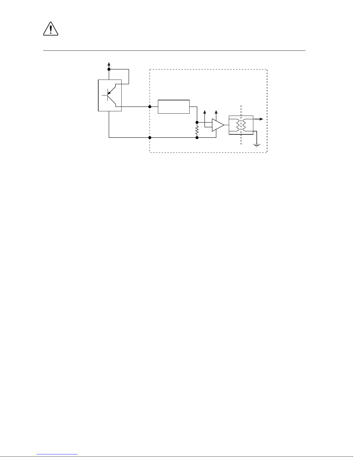
Wiring an Isolated Input
You can wire an isolated input to a sourcing output device.
Caution Do not apply a voltage greater than 30 VDC to the isolated inputs.
Voltage greater than 30 VDC may damage the IC-3173 (IP67).
Figure 29. Connecting an Isolated Input to a Sourcing Output Device
V
REF
C
ISO
Industrial Controller
Input
Sourcing
Output
Device
Current
Limiter
Power Supply
+
–
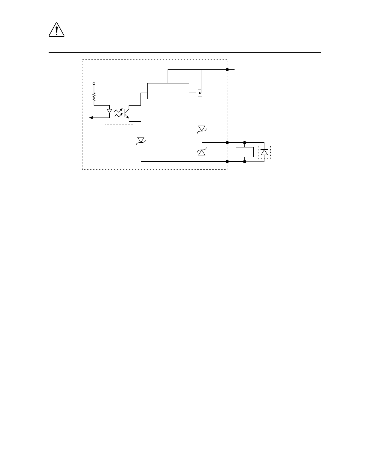
Wiring an Isolated Output
The digital isolated output circuits source current to external loads.
When an inductive load, such as a relay or solenoid, is connected to an output, a large counterelectromotive force may occur at switching time due to energy stored in the inductive load.
This flyback voltage can damage the outputs and the power supply.
To limit flyback voltages at the inductive load, install a flyback diode across the load. Mount
the flyback diode as close to the load as possible. Use this protection method if you connect
any of the isolated outputs on the IC-3173 (IP67) to an inductive load.
The following image shows an example of an isolated output wired to an external load with a
flyback diode installed across the load.
36 | ni.com | IC-317x User Manual
Page 38

Caution Do not draw more than 35 mA from each isolated output when V
ISO
is
5 V. Do not draw more than 80 mA from each isolated output when V
ISO
is 24 V.
Figure 30. Connecting an Isolated Output to an External Load
Digital Output
External Flyback
Diode for
Inductive Loads
V
ISO
C
ISO
V
CC
Industrial Controller
Load
Overcurrent
Protection Circuit
Connecting to Differential I/O
The IC-3173 (IP67) accepts differential (RS-422) line driver inputs. Each of the two
differential I/O can be configured as an output. Use shielded cables for all applications.
Unshielded cables are more susceptible to noise and can corrupt signals.
IC-317x User Manual | © National Instruments | 37
Page 39

Figure 31. Quadrature Encoder/RS-422 Input/Output Circuit
+
–
Diff I/O 0–
Diff I/O 0+
Diff I/O 1–
Diff I/O 1+
+3.3 V
+
–
10 kΩ 10 kΩ 10 kΩ 10 kΩ
EN
EN
7.5 kΩ 7.5 kΩ 7.5 kΩ
7.5 kΩ
Figure 32. Connecting Differential Line Drivers
Diff In 0+
Diff In 0–
Phase A
Phase A
Diff In 1+
Diff In 1–
Phase B
Phase B
External Device Industrial Controller
Twisted Pair
Twisted Pair
+
–
+
–
38 | ni.com | IC-317x User Manual
Page 40

Figure 33. Connecting Single-Ended Line Drivers
Diff In 0+
Diff In 0–
Phase A
Twisted Pair
Twisted Pair
Diff In 1+
Diff In 1–
Phase B
External Device Industrial Controller
+
–
+
–
TTL I/O
The following image shows the circuit for a bidirectional TTL I/O.
Figure 34. TTL Input/Output Circuit
100 Ω
TTL_OUT
TTL_OE
TTL_IN
10 kΩ
FB
TTL I/O
Power Input Connectors
The IC-3173 (IP67) requires a power supply to power the system and, if you want to use the
isolated outputs, a power supply to power the isolated outputs.
NI recommends the following accessories for the IC-3173 (IP67).
Cable
Part Number
4-position M12 T-coded pigtail power cable for IC-3173 (IP67), 3 meters 785930-01
4-position M12 T-coded power connector for IC-3173 (IP67) 785928-01
The following figure shows the system power connector.
IC-317x User Manual | © National Instruments | 39
Page 41

Figure 35. System Power Connector (IC-3173 (IP67))
1
2
4
3
1. C
2. V2
3. C
4. V1
Table 19. System Power Connector Terminals
Terminal Description
V
1
System power (9-30 VDC)
C Common signal
V
2
System power (9-30 VDC)
NI recommends the following accessories for the isolated power input of the IC-3173 (IP67).
Cable Part Number
4-position M12 A-coded pigtail ISO power cable for IC-3173 (IP67), 3
meters
785931-01
4-position M12 A-coded ISO power connector for IC-3173 (IP67) 785929-01
The following figure shows the terminal of the isolated power input connector.
Figure 36. Isolated Power Input Connector (IC-3173 (IP67))
4
3
1
2
1. C (Negative) Terminal
2. V (Positive) Terminal
3. No connect
4. No connect
Table 20. Isolated Power Connector Terminals
Terminal Description
C
ISO
Isolated common signal
V
ISO
Power for isolated outputs (4.5 to 30 VDC)
40 | ni.com | IC-317x User Manual
Page 42

Chassis Grounding Screw
Use the grounding screw to connect the chassis to earth ground. An earth ground connection is
optional.
RS-485/422/232 Serial Port
The IC-3173 (IP67) has a single serial port that can operate in either RS-485/422 mode or
RS-232 mode. Set the serial port mode in the BIOS setup utility.
The serial port is an 8-position A-code M12 connector, which can connect to serial devices,
such as PLCs, scanners, and lighting devices.
NI recommends the following serial cables for the IC-3173 (IP67).
Cable Part Number
8-position M12 A-coded pigtail serial cable for IC-3173 (IP67), 5 meters 785933-01
Figure 37. RS-485/422/232 Serial Port Pin Locations (IC-3173 (IP67))
Pin 1
2
3
4
5
6
7
8
Table 21. RS-485/422/232 Serial Port Pin Descriptions
Pin RS-485/422 Mode RS-232 Mode
1 No Connect No Connect
2 TXN Unused
3 TXP Unused
4 RXN GND
5 RXP Unused
6 Unused TX
7 Unused RX
8 GND Unused
IC-317x User Manual | © National Instruments | 41
Page 43

USB 3.0 Ports
The USB ports support USB peripheral devices such as USB flash drives, USB hard drives,
USB-to-IDE adapters, keyboards, mice, and USB cameras.
Figure 38. USB 3.0 Port Pin Locations (IC-3173 (IP67))
4
3
2
1
5
6
7
8
9
Table 22. USB 3.0 Port Pin Descriptions
Pin Signal Name Signal Description
1 VBUS Cable Power (+5 VDC)
2 D- USB Data -
3 D+ USB Data +
4 GND Ground for power return
5 StdA_SSRX- SuperSpeed receiver differential pair
6 StdA_SSRX+
7 GND_DRAIN Ground for signal return
8 StdA_SSTX- SuperSpeed transmitter differential pair
9 StdA_SSTX+
USB 2.0 Port
The USB port supports common USB peripheral devices such as USB flash drives, USB hard
drives, USB-to-IDE adapters, keyboards, mice, and USB cameras.
Figure 39. USB 2.0 Pin Locations (IC-3173 (IP67))
1
4
42 | ni.com | IC-317x User Manual
Page 44

Table 23. USB 2.0 Port Pin Descriptions
Pin Signal Name Signal Description
1 VBUS Cable Power (+5 VDC)
2 D- USB Data -
3 D+ USB Data +
4 GND Ground for power return
LED Indicators
The LED indicators are located on the front panel of the device. The IC-3173 (IP67) provides
the following LED indicators.
POWER LED
The following table lists the POWER LED indications.
Table 24. POWER LED Indications
LED Color LED Pattern Indication
Green Solid The IC-3173 (IP67) is powered from the V1 or V2 input.
— Off The IC-3173 (IP67) is powered off.
STATUS LED
The following table describes the STATUS LED indications.
IC-317x User Manual | © National Instruments | 43
Page 45

Table 25. STATUS LED Indications
LED
Color
LED State Indication
Yellow OFF The IC-3173 (IP67) initialized successfully and is ready for
use.
2 blinks (RT only) The device has automatically booted into safe mode.
This occurs when there is no software installed, which is the
out-of-box state, or the device has detected an error in its
software. Reinstall software on the IC-3173 (IP67).
3 blinks (RT only) The IC-3173 (IP67) has booted into safe mode.
4 blinks (RT only) The IC-3173 (IP67) has experienced two
consecutive software exceptions. The IC-3173 (IP67)
automatically restarts after an exception. After the second
exception, the IC-3173 (IP67) remains in the exception state,
alerting you to resolve the problem. Reinstall software on the
IC-3173 (IP67) or contact National Instruments.
Continuous
blink
This indicates one of the following errors.
(RT only) The IC-3173 (IP67) has not booted into NI Linux
Real-Time. The controller either booted into an unsupported
operating system, was interrupted during the boot process, or
detected an unrecoverable software error.
An internal power supply has failed. Check front-panel I/O
connections for shorts. Remove any shorts and cycle power to
the IC-3173 (IP67). If the problem persists, contact National
Instruments.
ON (RT only) The IC-3173 (IP67) is booting up.
(Windows only) An internal drive is being accessed.
Using the RESET Button
Pressing the RESET button resets the processor in the same manner as cycling power. If the
controller is powered but shut down, pressing the RESET button turns on the controller. You
can also use the RESET button to troubleshoot network connectivity.
The RESET button is located on the bottom of the controller.
1. Remove the IC-3173 (IP67) from any wet or dusty environment, as the product is not
rated IP67 while the reset screw is removed.
2. Remove the reset screw using a screwdriver. Retain the gasket.
3. Hold the RESET button for 5 seconds, and then release it to boot the IC-3173 (IP67) into
safe mode and enable Console Out.
44 | ni.com | IC-317x User Manual
Page 46

4. After booting the controller into safe mode, hold the RESET button again for 5 seconds to
enable IP reset, which resets the network adapter to its default configuration.
5. Reattach the reset screw using a recommended torque range of 2 Nm - 3 Nm with the
gasket in place. These values are recommended average values only. Variations in local
conditions may require deviations from these recommended values.
Safe Mode
When you boot the IC-3173 (IP67) into safe mode, it launches only the services necessary for
updating its configuration and installing software. To resume normal operations, press the
RESET button for less than 5 seconds.
IP Reset
Use IP reset to reset the TCP/IP settings when moving the system from one subnet to another
or when the current TCP/IP settings are invalid.
When the IC-3173 (IP67) is in the IP reset state, the IP address of the network port resets to
DHCP or a link-local address. You can then set up a new network configuration for the
IC-3173 (IP67) from a development machine on the same subnet, or you can connect the
IC-3173 (IP67) directly to the development computer.
Note By default, the target automatically attempts to connect to the network using
DHCP. If the target is unable to initiate a DHCP connection, the target connects to
the network with a link-local IP address (169.254.x.x).
Mounting the IC-3173 (IP67)
The IC-3173 (IP67) has 11 screw holes with M4x0.7 thread and 8mm depth on both sides of
the device that can be used for mounting.
Caution Mounting the IC-3173 (IP67) to a hot surface may result in undesirable
performance. Refer to the IC-3173 (IP67) Specifications for temperature
specifications.
To obtain the maximum allowable ambient temperature, you must mount the IC-3173 (IP67)
vertically. The following figures provide dimensional drawings and clearance information for
the IC-3173 (IP67).
IC-317x User Manual | © National Instruments | 45
Page 47

Figure 40. Front View Dimensions
IC-3173
IP67 Industrial Controller
ISO PWR IN
5-24V
CONNECTOR 2
CONNECTOR 1
SYS PWR IN
9-30V
150W MAX
RESET
CONNECTOR 0
POWER STATUS
SS
DP
DIGITAL I/O
SS
PoE 4
PoE 2PoE 1
PoE 3
SYNC
3.65 in (92.71 mm)
2X 1.3 in (33.01 mm)
1.36 in (34.44 mm)
2X 2.28 in (57.79 mm)
4.12 in (104.55 mm)
2X 6.48 in (164.68 mm)
2X 5.58 in (141.82 mm)
2.42 in (61.37 mm)
3.27 in (82.96 mm)
1.05 in (26.71 mm)
3.82 in (97.11 mm)
7.59 in (192.77 mm)
2X 6.02 in (152.97 mm)
2.89 in (73.46 mm)
3.65 in (92.65 mm)
2.43 in (61.79 mm)
1.05 in (26.74 mm)
0 in (0 mm)
0 in (0 mm)
4X .53 in (13.34 mm)
1.38 in (34.92 mm)
2.26 in (57.31 mm)
3.65 in (92.71 mm)
46 | ni.com | IC-317x User Manual
Page 48

Figure 41. Side View Dimensions
7.60 in
(193.11 mm)
.02 in
(.38 mm)
0 in (0 mm)
12.64 in (320.92 mm)
12.09 in (307.03 mm)
7.29 in (185.14 mm)
5.86 in (148.77 mm)
8.72 in (221.51 mm)
10.15 in (257.89 mm)
4.43 in (112.39 mm)
1.56 in (39.65 mm)
2.99 in (76.02 mm)
11X M4 HOLE
.32 in (8 mm)
0 in (0 mm)
1.29 in (32.87 mm)
3.79 in (96.37 mm)
6.29 in (159.87 mm)
7.59 in (192.73 mm)
2X 12.42 in (315.52 mm)
3X 12.49 in (317.11 mm)
12.64 in (320.92 mm)
Clearance Requirements
The IC-3173 (IP67) installation must meet the following space and cabling clearance
requirements for optimum cooling:
• Allow 50.8 mm (2.0 in.) on the top and bottom of the IC-3173 (IP67) for air circulation.
• Allow 50.8 mm (2.0 in.) on the sides of the IC-3173 (IP67) for air circulation.
• Allow enough space in front of the IC-3173 (IP67) to connect cables.
IC-317x User Manual | © National Instruments | 47
Page 49

Figure 42. Clearance Requirements for the IC-3173 (IP67)
IC-3173
IP67 Industrial Controller
ISO PWR IN
5-24V
CONNECTOR 2
CONNECTOR 1
SYS PWR IN
9-30V
150W MAX
RESET
CONNECTOR 0
POWER STATUS
SS
DP
DIGITAL I/O
SS
PoE 4
PoE 2PoE 1
PoE 3
SYNC
2 in (50.8 mm)
2 in
(50.8 mm)
Software Options
Use the following software to develop applications with the IC-317x. Refer to the IC-317x
Getting Started Guide for information about installing software.
• NI Industrial Controller Device Drivers 15.5 or later driver software.
• One of the following options for developing machine vision applications:
– LabVIEW 2014 SP1 or later, LabVIEW Real-Time 2014 SP1 or later, the NI Vision
Development Module 2015 SP1 or later.
– NI Vision Builder for Automated Inspection (Vision Builder AI) 2015 or later.
• Software for using and reconfiguring the IC-317x FPGA. Different configurations are
referred to as hardware personalities, and are defined by bitfiles. NI Industrial Controller
Device Drivers include a reconfigurable I/O personality that you can use out of the box.
Install the following software if you need to compile a custom personality for your
application:
– LabVIEW 2014 SP1 or later and LabVIEW FPGA Module 2014 SP1 or later—You
must install the LabVIEW FPGA Module to reconfigure the default personality of
the IC-317x FPGA.
48 | ni.com | IC-317x User Manual
Page 50

IEEE 1588 Precision Time Protocol References
IC-317x controllers are compatible with the IEEE 1588 Precision Time Protocol (PTP). Visit
ni.com/info and enter the following info codes for more information on the IEEE 1588 PTP
and IC-317x industrial controllers.
• ICConnect1588 - Provides information on which IC-317x port to connect to an IEEE
1588 PTP Grand Master.
• ICLinkSpeed1588 - Provides information on which link speed optimizes IEEE 1588
PTP synchronization performance on the IC-317x.
• ICModSysTime1588 - Provides information on modifying system time on the IC-317x
when NI-TimeSync is installed.
• swsync - Provides an introduction to distributed clock synchronization and the IEEE
Precision Time Protocol.
BIOS Configuration and System Recovery
You can change the configuration settings for the IC-317x in the BIOS setup utility. The BIOS
is the low-level interface between the hardware and PC software that configures and tests your
hardware when you boot the system. The BIOS setup utility includes menus for configuring
settings and enabling features.
Most users do not need to use the BIOS setup utility. The system ships with default settings
that work well for most configurations.
Entering BIOS Setup
Complete the following steps to start the BIOS setup utility.
1. Connect a monitor to one of the DisplayPort connectors on the IC-317x.
2. Connect a USB keyboard to one of the USB ports on the IC-317x.
3. Power on or reboot the IC-317x.
4. Immediately hold down the <Delete> key until the BIOS setup utility appears.
The Main setup menu is displayed when you first enter the BIOS setup utility.
BIOS Setup Utility Keyboard Navigation
Use the following keys to navigate through the BIOS setup utility:
IC-317x User Manual | © National Instruments | 49
Page 51

Table 26. Navigation Keys
Key(s) Function(s)
Left Arrow, Right
Arrow
Move between the different setup menus. If you are in a submenu,
these keys have no effect, and you must press <Esc> to leave the
submenu first.
Up Arrow, Down
Arrow
Move between the options within a setup menu.
<Enter> Enter a submenu or display all available settings for a highlighted
configuration option.
<Esc> Return to the parent menu of a submenu. At the top-level menus, this
key serves as a shortcut to the Exit menu.
<+>, <-> Cycle between all available settings for a selected configuration option.
<Tab> Select time and date fields.
<F9> Load the optimal default values for all BIOS configuration settings.
The optimal default values are the same as the shipping configuration
default values.
<F10> Save settings and exits the BIOS setup utility.
Main Setup Menu
The Main setup menu reports the following configuration information:
• BIOS Version and Build Date—These values indicate the version of the controller BIOS
and the date on which the BIOS was built.
• Embedded Firmware Version—This value identifies the built-in hardware capabilities.
• Processor Type, Base Processor Frequency, and Active Processor Cores—These values
indicate the type of processor used in the controller, the speed of the processor, and the
number of active processor cores.
• Total Memory—This value indicates the size of system RAM detected by the BIOS.
The Main setup menu includes System Date and System Time settings, which are the most
commonly accessed and modified BIOS settings. These settings are stored in a battery-backed
real-time clock. In the BIOS menu, use <+> and <-> in conjunction with <Enter> and <Tab>
to change these values. You can also change these settings using NI-MAX or Vision Builder
AI.
• System Date—This value controls the date.
• System Time—This value controls the time of day.
50 | ni.com | IC-317x User Manual
Page 52

Advanced Menu
This menu contains BIOS settings that normally do not require modification. If you have
specific problems such as unbootable disks or resource conflicts, you may need to examine
these settings.
The Advanced setup menu includes the following submenus:
• SATA Configuration
• CPU Configuration
• Video Configuration
• Power/Wake Configuration
• AMT Configuration
• USB Configuration
• Serial Port Configuration
SATA Configuration Submenu
Use this submenu to apply custom configurations to the internal disk drive of the IC-317x.
Normally, you do not need to modify these settings, as the factory default settings provide the
most compatible and optimal configuration.
• SATA Controller(s)—Enables or disables the SATA controller. The default is Enabled.
– SATA Port 0—Enables or disables SATA port 0.
– SATA Port 1—Enables or disables SATA port 1.
– SATA Port 3—Enables or disables SATA port 3.
• Onboard Storage—Lists the SATA disk drive and displays the size of the disk.
CPU Configuration Submenu
Use this submenu to apply custom configurations to the internal processor of the device.
Normally, you do not need to modify these settings, as the factory default settings provide the
most compatible and optimal configuration.
• Hyper-Threading—This setting specifies whether or not to enable Intel Hyper-Threading
technology in the processor. When enabled, performance may increase because virtual
processing cores are enabled, but software jitter may increase. The default setting is
Disabled.
• Enabled CPU Cores—This setting specifies the number of processing cores that are
enabled. The default setting is All.
• Turbo Boost—This setting specifies whether or not to enable Intel Turbo Boost
technology. When enabled, if current conditions within the processor allow, the processor
operates at frequencies higher than the base frequency. This may increase processing
performance, but software jitter may increase. The default setting is Enabled.
• C-States—This setting specifies whether or not to enable CPU power management. When
enabled, the processor may achieve maximum operating frequency when Turbo Boost is
enabled, but software jitter may increase. The default setting is Enabled.
• Hardware Prefetcher—This setting specifies whether or not to enable the hardware
prefetcher. Enabling this setting may increase performance by prefetching portions of
IC-317x User Manual | © National Instruments | 51
Page 53

memory for the processor, but software jitter may increase. The default setting is
Enabled.
• Adjacent Cache Prefetcher—This setting specifies whether or not to enable the adjacent
cache line prefetcher. Enabling the adjacent cache prefetcher may increase performance
by prefetching portions of memory for the processor, but software jitter may increase.
The default setting is Enabled.
Video Configuration Submenu
Use this submenu to enable or disable the display interface.
• Primary Display—This setting can disable the onboard video for the product. Setting the
value to Onboard Video enables the internal display capabilities and the DisplayPort
connectors. Setting the value to Disabled disables the internal display capabilities and the
DisplayPort connectors. The default setting is Onboard Video.
Power/Wake Configuration Submenu
The Power/Wake configuration submenu contains the power and wake settings for the
IC-317x. The factory default settings provide the most compatible and optimal configuration.
• Restore After Power Loss—This setting specifies the power state that the IC-317x should
return to after power is lost. Valid values are Stay Off and Turn On. The default value is
Turn On. When set to Stay Off, the IC-317x returns to the soft off power state after
power is restored. When set to Turn On, the IC-317x powers on when power is restored.
• Power Button Off Behavior—This setting specifies how the system responds to the power
button. Valid options are Normal and Disabled. The default value is Normal. If the value
is Normal, the system responds to the power button as defined by the OS. If the value is
Disabled, pressing the power button has no effect when the system is on. When the
system is in the soft off state, pushing the power button always powers on the system.
This setting has no effect on the IC-3173 (IP67)
AMT Configuration Submenu
The AMT configuration submenu contains settings to configure Intel Active Management
Technology.
• Management Engine Setup Prompt—This setting specifies whether or not to show the
Intel Management Engine prompt during boot. Enabling this option enables the other
options on this submenu. The default setting is Disabled.
• Unconfigure Management Engine—This setting specifies whether or not to unconfigure
the Management Engine during the next boot. The default setting is Disabled.
• USB-Based Configuration—This setting specifies whether or not to search connected
USB drives for AMT configuration files. The system prompts the user if it finds any
configuration files. The default setting is Disabled.
52 | ni.com | IC-317x User Manual
Page 54

USB Configuration Submenu
The USB configuration submenu contains the USB host ports settings. The factory default
settings provide the most compatible and optimal configuration.
• USB Devices—This item lists the total number of devices detected in the system,
categorized by device type.
• Legacy USB Support—This setting specifies whether legacy USB support is enabled.
Legacy USB support refers to the ability to use a USB keyboard and mouse in a legacy
operating system such as DOS.
• Overcurrent Reporting—This setting allows the BIOS to notify the operating system
about any USB ports that source too much current. The default value is Disabled.
Hardware overcurrent protection is always active and cannot be disabled.
• Transfer Timeout—This setting specifies the timeout value for Control, Bulk, and
Interrupt USB transfers. The default value is 20 seconds.
• Device Reset Timeout—This setting specifies the number of seconds the POST waits for
a USB mass-storage device to start. The default value is 20 seconds.
• Device Power-Up Delay—This setting specifies the maximum time a device takes before
enumerating. Valid options are Auto and Manual. The default value is Auto. When set to
Auto, a root port is granted 100 ms, and the delay value of a hub port is assigned from the
hub descriptor.
• Device Power-Up Delay in Seconds—This setting specifies the number of seconds the
POST waits for a USB device or hub to power on. This setting is only visible when the
Device Power-Up Delay is set to Manual. The default value is 5 seconds.
• Mass Storage Devices—This list allows you to configure how the BIOS presents the USB
mass-storage device to the system for each detected USB mass-storage device. This
option presents a USB mass-storage device as a floppy, Zip, hard disk, or CD-ROM
drive. The default value is Auto, which allows the BIOS to treat small USB flash disk
drives as floppy drives and larger USB flash disk drives as hard disk drives.
Serial Port Configuration Submenu
Use this submenu to view the serial port configuration.
• RS485/RS232 Select—This setting selects the transceiver mode between RS-232 and
RS-485. The default value is RS485.
• RS-485 Configuration—Use this menu to configure the RS-485/422 wire-mode. The
default value is Auto.
Boot Menu
This screen displays the boot order of devices associated with the IC-317x and allows you to
configure the boot settings.
The Boot setup menu includes the following submenus:
• Boot Settings Configuration—Use this setting to access the Boot Settings Configuration
submenu.
• PXE Network Boot—This setting specifies whether or not the PXE network boot agent is
enabled. The default value is Disabled. To enable this setting, you must select Enable
and then select Save & Exit to restart the device. When this setting is enabled, the Intel
IC-317x User Manual | © National Instruments | 53
Page 55

Boot Agent is visible in the Boot Option Priorities menu. This allows you to boot from a
PXE server on the local subnet. Note that the Intel Boot Agent device names are preceded
by IBA GE Slot in the Boot Option Priorities menu.
• Boot Option Priorities—These settings specify the order in which the BIOS attempts to
boot from bootable devices, including the local hard disk drive, removable devices such
as USB flash disk drives or USB CD-ROM drives, or the PXE network boot agent. The
BIOS will first attempt to boot from the device associated with Boot Option #1, followed
by Boot Option #2 and Boot Option #3. If multiple boot devices are not present, the
BIOS setup utility will not display all of these configuration options. To select a boot
device, press <Enter> on the desired configuration option and select a boot device from
the resulting menu. You can also disable individual boot options by selecting Disabled.
Note For each detected drive, the boot option may list a UEFI option and an option
without UEFI. This depends on whether the drive supports booting with UEFI,
legacy BIOS, or both. If a drive is not displayed as a boot option, use the Drive or
Device BBS Priorities setting to change the relative priority of the drive.
Boot Settings Configuration Submenu
• Setup Prompt Timeout—This setting specifies the amount of time the system waits for a
BIOS Setup menu keypress (the <Delete> key) in units of a second. The default value is 1
for a delay of one second.
• Bootup NumLock State—This setting specifies the power-on state of the keyboard
NumLock setting. The default value is On.
Save & Exit Menu
The Save & Exit setup menu includes all available options for exiting, saving, and loading the
BIOS default configuration. You can also press <F9> to load BIOS default settings and <F10>
to save changes and exit setup.
The Save & Exit setup menu includes the following settings:
• Save Changes and Reset—Any changes made to BIOS settings are stored in NVRAM.
The setup utility then exits and reboots the controller.
• Discard Changes and Reset—Any changes made to BIOS settings during this session
since the last save are discarded. The setup utility then exits and reboots the controller.
• Save Changes—Any changes made to BIOS settings during this session are committed to
NVRAM. The setup utility remains active, allowing further changes.
• Discard Changes—Any changes made to BIOS settings during this session since the last
save are discarded. The BIOS setup continues to be active.
• Restore Defaults—This option restores all BIOS settings to the factory default. This
option is useful if the controller exhibits unpredictable behavior due to an incorrect or
inappropriate BIOS setting. The <F9> key can also be used to select this option.
• Save as User Defaults—This option saves a copy of the current BIOS settings as the User
Defaults. This option is useful for preserving custom BIOS setup configurations.
• Restore User Defaults—This option restores all BIOS settings to the values last saved as
user defaults.
• Boot Override—This option lists all possible bootable devices and allows the user to
override the Boot Option Priorities list for the current boot. If no changes have been
54 | ni.com | IC-317x User Manual
Page 56

made to the BIOS setup options, the system will continue booting to the selected device
without first rebooting. If BIOS setup options have been changed and saved, a reboot is
required and the boot override selection will not be valid.
Restoring the NI Linux Real-Time Operating System
Complete the following steps to restore the NI Linux Real-Time operating system to its factory
default condition. These steps do not restore the BIOS settings to factory default. Use the
Restore Defaults option in the Save & Exit Menu of the BIOS setup utility to restore the BIOS
settings.
Caution Restoring the operating system erases the contents of the hard drive. Back
up any files you want to keep before restoring the hard drive.
1. Start the IC-317x in safe mode. To start in safe mode, apply power, turn on the device,
press the RESET button for more than 5 seconds, then release the button.
2. Launch NI MAX on the development computer.
3. In the MAX configuration tree, expand Remote Systems.
4. Right-click the name of the IC-317x you want to restore and select Format Disk.
5. Enter the username and password for the device. By default, the username is admin and
the password field is blank.
6. Click Format.
7. After formatting is complete, a confirmation dialog window appears. Click Close.
8. Refer to the IC-317x Getting Started Guide for information about installing software and
configuring the device.
Restoring the Windows Operating System
You can restore the Windows operating system on the hard drive of the IC-317x from the
reinstallation DVD shipped with device.
Note Restoring the operating system erases the contents of the hard drive. Back up
any files you want to keep before restoring the hard drive.
Creating a Bootable USB Flash Drive
You can create a bootable USB flash drive from the reinstallation DVD if you do not have a
USB DVD drive to connect to the IC-317x. The USB flash drive must be at least 8 GB. Ensure
the USB flash drive appears as a Removable Drive in Windows. Avoid using drives that
appear as Fixed Disk drives. Complete the following steps to prepare the USB flash drive for
recovery.
Note If you have an external USB DVD drive, you can use the external DVD drive
to restore Windows without creating a bootable USB flash drive. Proceed to the next
section if you are using an external DVD drive.
1. Insert the USB flash drive into a computer with a DVD drive running Windows, and wait
for the flash drive to be recognized.
2. Open a command prompt as an administrator.
3. Type diskpart.exe and press <Enter>.
IC-317x User Manual | © National Instruments | 55
Page 57

4. Type list disk and press <Enter>.
5. Identify the drive number that corresponds to the USB flash drive.
6. Type select disk x, where x is the drive number of the USB flash drive, and press
<Enter>. For example, in the following image, the USB flash drive is disk number 5. The
command is select disk 5.
Caution Following this process will delete all data on the USB flash drive.
7. Type clean and press <Enter>. This command deletes all data from the USB flash drive.
8. Type create partition primary and press <Enter>.
9. Type active and press <Enter>
10. Type format fs=ntfs quick and press <Enter> to format the USB flash drive.
11. Type assign letter free volume letter, where free volume letter is a
letter not currently associated with any disk drives. For example, assign letter K.
12. Copy the contents of the reinstallation DVD to the root of the USB flash drive.
The USB flash drive is now bootable and will install Windows.
Reinstalling Windows
Complete the following steps to use the recovery media to install Windows.
1. Connect the bootable USB flash drive to one of the USB ports on the IC-317x. Or
connect an external DVD drive to one of the USB ports on the IC-317x and insert the
recovery DVD into the external drive.
2. Connect a USB hub to the other USB port on the IC-317x. Connect a keyboard and
mouse to the USB hub. If a USB hub is not available, the keyboard can be used to
navigate the recovery software.
3. Power on the IC-317x.
4. Press the <F10> key on the keyboard.
5. Select the bootable USB flash drive or the DVD drive.
56 | ni.com | IC-317x User Manual
Page 58

6. Press any key to boot from the recovery media.
7. Follow the on-screen instructions to format the hard drive and install the operating
system.
After restoring the operating system, reinstall any software and drivers onto the IC-317x.
Where to Go Next
The following documents and resources contain information you may find helpful as you use
the IC-317x in an application. Refer to the National Instruments Product Manuals Library at
ni.com/manuals for the most recent versions of product documentation.
• IC-317x Specifications—Contains detailed specifications for the IC-317x.
• IC-317x Getting Started Guide—Explains how to install and configure the software
necessary to use the IC-317x, and how to get started using the hardware.
• NI CVS I/O Accessory User Manual—Contains installation and operation instructions for
the NI CVS I/O Accessory.
Resources for LabVIEW Users
Documentation for LabVIEW is available from the Help menu on the LabVIEW toolbar.
Access documentation for the NI Vision Development Module, NI-IMAQdx, and Vision RIO
by selecting Start»All Programs»National Instruments»Vision»Documentation.
Documentation for the MAX configuration software is available from the Help menu on the
MAX toolbar. Specific information about using MAX with NI Vision hardware is available by
selecting Help»Help Topics»NI Vision»NI-IMAQdx.
National Instruments Example Finder—LabVIEW contains an extensive library of VIs and
example programs. To access the NI Example Finder, open LabVIEW and select Help»Find
Examples.
Resources for Vision Builder AI Users
Refer to the NI Vision Builder for Automated Inspection Tutorial to learn how to perform basic
machine vision techniques using Vision Builder AI. You can access the NI Vision Builder for
Automated Inspection Tutorial and other documentation by selecting Start»All Programs»
National Instruments»Vision Builder AI»Documentation. You can also access context help
within Vision Builder AI by clicking the Show Context Help button on the Vision Builder AI
toolbar.
Examples of common Vision Builder AI inspections are installed to the <Vision Builder
AI>\Examples directory, where <Vision Builder AI> is the location Vision Builder AI is
installed.
Worldwide Support and Services
The NI website is your complete resource for technical support. At ni.com/support, you have
access to everything from troubleshooting and application development self-help resources to
email and phone assistance from NI Application Engineers.
IC-317x User Manual | © National Instruments | 57
Page 59

Visit ni.com/services for NI Factory Installation Services, repairs, extended warranty, and
other services.
Visit ni.com/register to register your NI product. Product registration facilitates technical
support and ensures that you receive important information updates from NI.
A Declaration of Conformity (DoC) is our claim of compliance with the Council of the
European Communities using the manufacturer’s declaration of conformity. This system
affords the user protection for electromagnetic compatibility (EMC) and product safety. You
can obtain the DoC for your product by visiting ni.com/certification. If your product supports
calibration, you can obtain the calibration certificate for your product at ni.com/calibration.
NI corporate headquarters is located at 11500 North Mopac Expressway, Austin, Texas,
78759-3504. NI also has offices located around the world. For telephone support in the United
States, create your service request at ni.com/support or dial 1 866 ASK MYNI (275 6964). For
telephone support outside the United States, visit the Worldwide Offices section of ni.com/
niglobal to access the branch office websites, which provide up-to-date contact information,
support phone numbers, email addresses, and current events.
Information is subject to change without notice. Refer to the NI Trademarks and Logo Guidelines at ni.com/trademarks for
information on NI trademarks. Other product and company names mentioned herein are trademarks or trade names of their
respective companies. For patents covering NI products/technology, refer to the appropriate location: Help»Patents in your
software, the patents.txt file on your media, or the National Instruments Patent Notice at ni.com/patents. You can find
information about end-user license agreements (EULAs) and third-party legal notices in the readme file for your NI product. Refer
to the Export Compliance Information at ni.com/legal/export-compliance for the NI global trade compliance policy and how
to obtain relevant HTS codes, ECCNs, and other import/export data. NI MAKES NO EXPRESS OR IMPLIED WARRANTIES AS
TO THE ACCURACY OF THE INFORMATION CONTAINED HEREIN AND SHALL NOT BE LIABLE FOR ANY ERRORS. U.S.
Government Customers: The data contained in this manual was developed at private expense and is subject to the applicable
limited rights and restricted data rights as set forth in FAR 52.227-14, DFAR 252.227-7014, and DFAR 252.227-7015.
© 2016—2017 National Instruments. All rights reserved.
375285C-01 September 1, 2017
 Loading...