

Page 1

National Instruments IC-3121 Manual
Get Pricing & Availability at
ApexWaves.com
Call Today: 1-800-915-6216
Email: sales@apexwaves.com
https://www.apexwaves.com/modular-systems/national-instruments/industrial-controllers/IC-3121
Page 2

USER MANUAL
IC-3121
Industrial Controller
This document contains detailed electrical and mechanical information for the National
Instruments IC-3121.
Contents
Hardware Overview.................................................................................................................. 1
Connector Pinouts............................................................................................................. 2
LED Indicators................................................................................................................14
Using the RESET Button................................................................................................ 18
Software Options.....................................................................................................................19
BIOS Configuration and System Recovery............................................................................ 19
Entering BIOS Setup.......................................................................................................19
BIOS Keyboard Navigation............................................................................................ 20
Main Menu......................................................................................................................20
Advanced Menu.............................................................................................................. 20
Boot Menu.......................................................................................................................21
Save & Exit Menu...........................................................................................................23
Restoring the NI Linux Real-Time Operating System....................................................24
Restoring the Windows Operating System..................................................................... 24
Mounting the IC-3121.............................................................................................................26
Securing the IC-3121 to a Mount....................................................................................30
Clearance Requirements................................................................................................. 30
Where to Go Next................................................................................................................... 31
Worldwide Support and Services............................................................................................32
Hardware Overview
The IC-3121 front panel consists of a VGA port, RJ50 serial port, two USB 2.0 ports, a
10/100/1000 Ethernet port, and two USB 3.0 ports.
The IC-3121 front panel also includes LEDs for communicating system status and a 44-pin
Digital I/O port. The Digital I/O port offers 8 isolated inputs, 8 isolated outputs, 2 bidirectional
differential I/O (RS-422) or single-ended input lines that can be used with a quadrature
encoder, and 8 bidirectional TTL lines.
Page 3
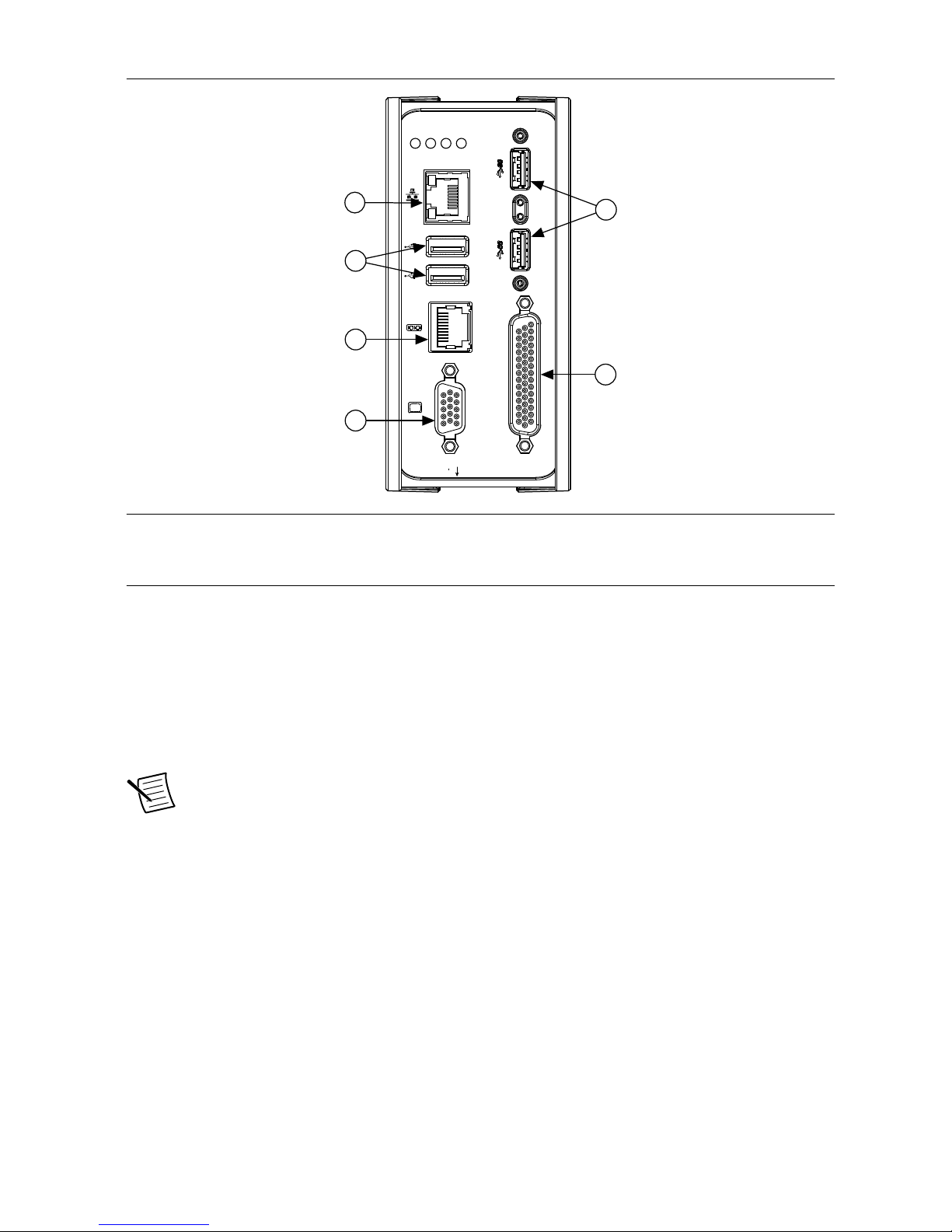
Figure 1. IC-3121 Front Panel Connectors
IC-3121
Industrial Controller
RESET
DIGITAL I/O
10/100/
1000
ACT/
LINK
USER1
USER2
PWR/
FAULT
STATUS
5
3
6
1
2
4
1. VGA Connector
2. RS-232/RS-485 Serial Port
3. USB 2.0 Ports
4. Gigabit Ethernet Port
5. USB 3.0 Ports
6. 44-pin Digital I/O Connector
Connector Pinouts
The IC-3121 provides the following connectors.
Chassis Grounding Screw
Use the grounding screw to connect the chassis to earth ground. An earth ground connection is
optional.
Note An earth ground connection does not connect C or C
ISO
to earth ground.
2 | ni.com | IC-3121 User Manual
Page 4
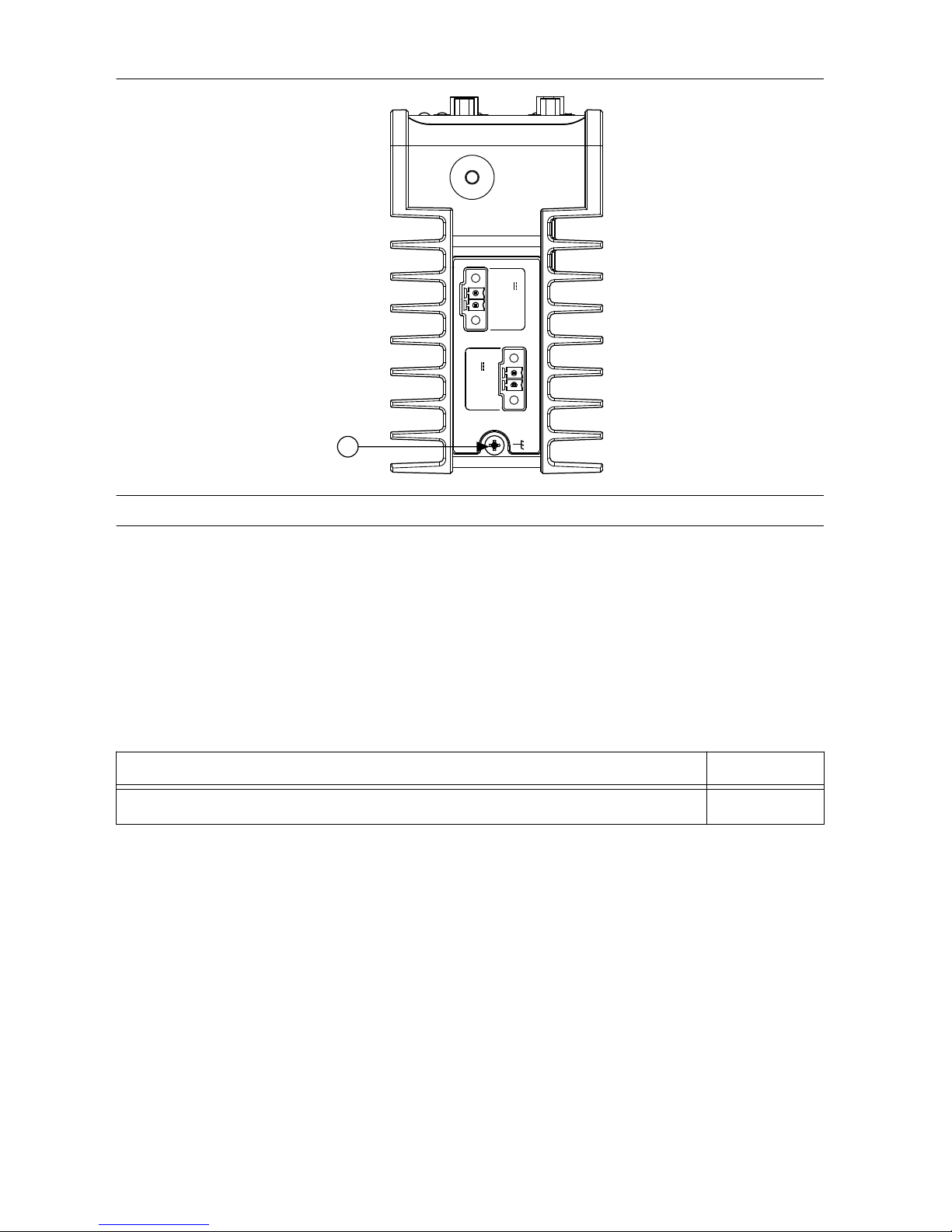
Figure 2. Chassis Grounding Screw
SYSTEM
12-24 V
C V
ISO
5-24 V
1
C
ISO
V
ISO
1. Chassis Grounding Screw
Power Input Connectors
The IC-3121 requires a power supply to power the system. If needed for your application, an
additional power source is required to power the isolated outputs.
The same power supply may be used for both the system power and isolated outputs power if
isolation is not required and the power supply meets the voltage and power requirements for
both inputs. Refer to the IC-3121 Specifications for power requirements.
NI recommends the following power supply for the IC-3121.
Power Supply
Part Number
NI PS-15 Industrial Power Supply, to power the system or isolated outputs 781093-01
IC-3121 User Manual | © National Instruments | 3
Page 5
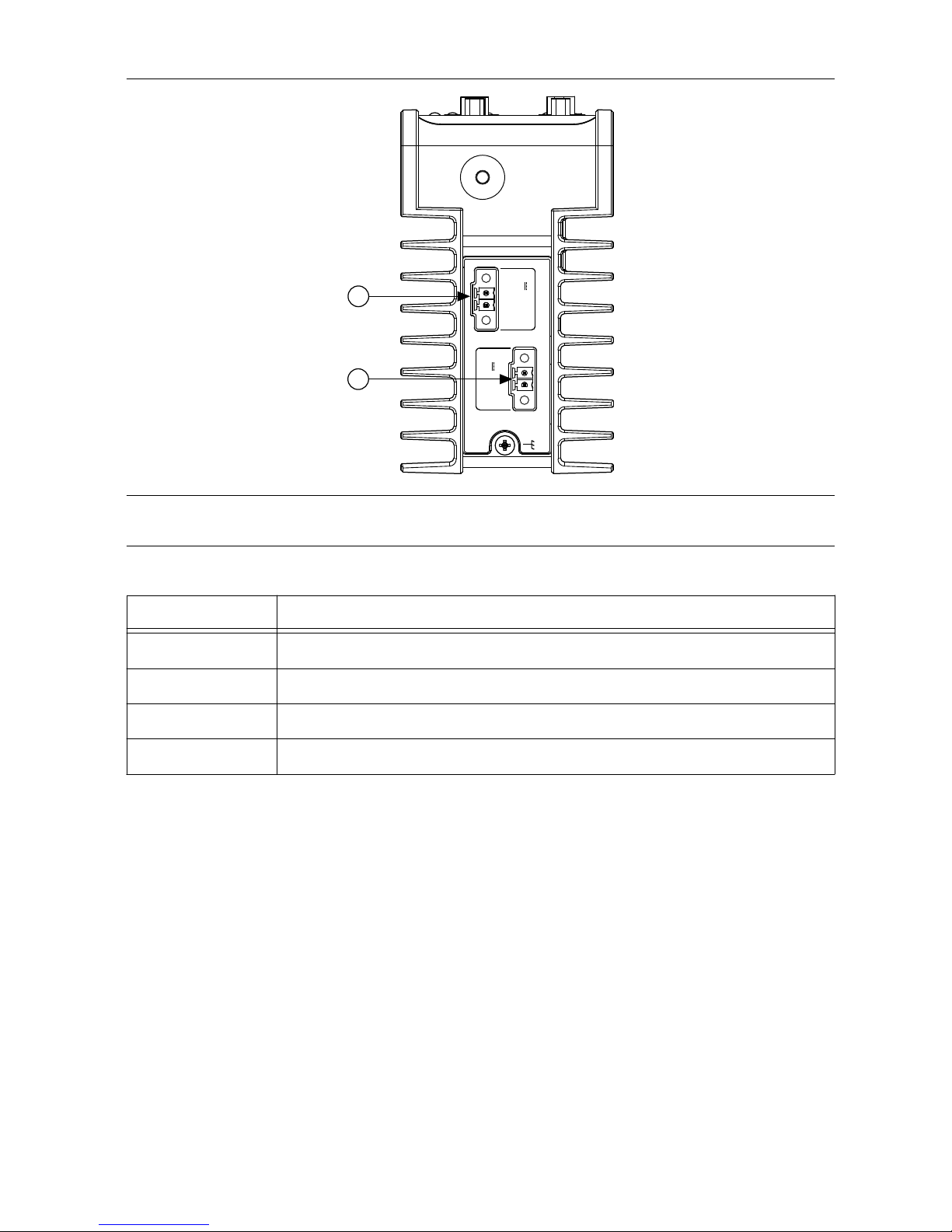
Figure 3. Power Connectors
SYSTEM
12-24 V
C V
ISO
5-24 V
1
2
C
ISO
V
ISO
1. System Power Connector
2. Isolated Outputs Power Connector
Table 1. Power Connector Terminals
Terminal Description
C Common signal
V System power (12-24 VDC)
C
ISO
Isolated common signal
V
ISO
Power for isolated outputs (5-24 VDC)
Ethernet Port
The IC-3121 provides a Gigabit Ethernet port. The Ethernet port provides a connection
between the IC-3121, a network, and other Ethernet devices. The IC-3121 automatically
detects the speed of the connection and configures itself accordingly.
A CAT 5e or CAT 6 1000Base-T Ethernet cable is required to achieve 1,000 Mbps (Gigabit)
Ethernet performance. CAT 5 Ethernet cables are not guaranteed to meet the necessary
requirements. While CAT 5 cables may appear to work at 1,000 Mbps, CAT 5 cables can cause
bit errors, resulting in degraded or unreliable network performance.
(Windows only) The network Ethernet port provides Wake-on-LAN functionality from the
power off state when associated with the Intel® driver. Wake-on-LAN must be enabled in the
Power Management tab of the Intel I210 Gigabit Network Connection Properties dialog for the
primary Ethernet port in Device Manager. The NI GigE Vision driver (NI-GEV) does not
support Wake-on-LAN.
4 | ni.com | IC-3121 User Manual
Page 6
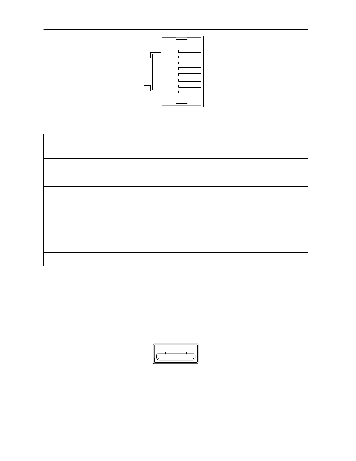
Figure 4. Ethernet Port Pin Locations
1
2
3
4
5
6
7
8
Table 2. Ethernet Port Pin Descriptions
Pin Fast Ethernet (100 Mbps) Gigabit Ethernet
MDI MDI-X
1 TX+ BI_DA+ BI_DB+
2 TX- BI_DA- BI_DB-
3 RX+ BI_DB+ BI_DA+
4 No Connect BI_DC+ BI_DD-
5 No Connect BI_DC- BI_DD-
6 RX- BI_DB- BI_DA-
7 No Connect BI_DD+ BI_DC+
8 No Connect BI_DD- BI_DC-
USB 2.0 Ports
The USB ports support common USB peripheral devices such as USB flash drives, USB hard
drives, USB-to-IDE adapters, keyboards, mice, and USB cameras.
(RT only) LabVIEW usually maps USB mass-storage devices to the /U, /V, /W, or /X drive,
starting with the /U drive if it is available. Refer to the LabVIEW Help for more information.
Figure 5. USB 2.0 Pin Locations
4
3
2
1
IC-3121 User Manual | © National Instruments | 5
Page 7
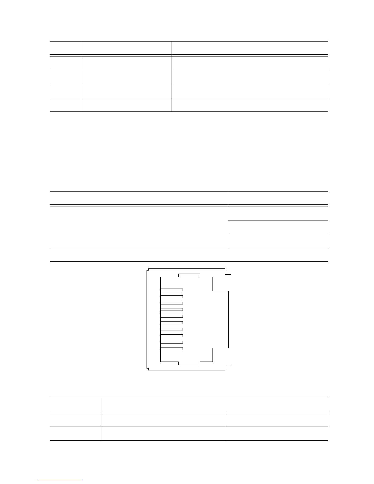
Table 3. USB 2.0 Port Pin Descriptions
Pin Signal Name Signal Description
1 VBUS Cable Power (+5 VDC)
2 D- USB Data -
3 D+ USB Data +
4 GND Ground for power return
RS-485/422/232 Serial Port
The IC-3121 has a single serial port that can operate in either RS-485/422 mode or RS-232
mode. Set the serial port mode in the BIOS setup utility.
The serial port is a 10-position RJ50 modular jack, which can connect to serial devices, such
as PLCs, scanners, and lighting devices.
NI recommends the following serial cables for the IC-3121.
Cable Part Number
RJ50 10-position modular plug to DB-9 serial cable 182845-01 for 1 meter cable
182845-02 for 2 meter cable
182845-03 for 3 meter cable
Figure 6. RS-485/422/232 Serial Port Pin Locations
3
4
5
6
7
8
9
10
1
2
Table 4. RS-485/422/232 Serial Port Pin Descriptions
Pin RS-485/422 Mode RS-232 Mode
1 No Connect No Connect
2 TXD- Unused
6 | ni.com | IC-3121 User Manual
Page 8
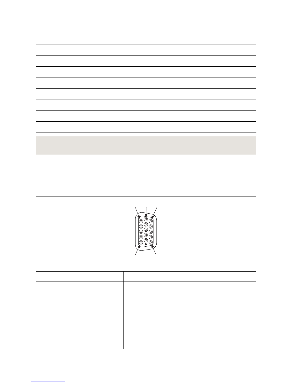
Table 4. RS-485/422/232 Serial Port Pin Descriptions (Continued)
Pin RS-485/422 Mode RS-232 Mode
3 TXD+ Unused
4 No Connect No Connect
5 No Connect No Connect
6 RXD- GND
7 RXD+ Unused
8 Unused TXD
9 Unused RXD
10 GND GND
Related Information
Serial Port Configuration Submenu on page 21
VGA Port
Use the VGA port to connect a monitor to the IC-3121. Use any standard 15-pin VGA cable to
access the VGA port. The VGA port has a maximum resolution of 1920 x 1200 at 60 Hz.
Figure 7. VGA Port Pin Locations
5 15
11
6
1
10
Pin
Signal Name Signal Description
1 RED Red analog video signal
2 GREEN Green analog video signal
3 BLUE Blue analog video signal
4 RESERVED Reserved
5 GND Ground reference
6 RED RETURN Ground reference
IC-3121 User Manual | © National Instruments | 7
Page 9
Pin Signal Name Signal Description
7 GREEN RETURN Ground reference
8 BLUE RETURN Ground reference
9 PWR 5 V power for DDC
10 GND Ground return for power
11 NC No connect
12 DDC_D Data signal of serial communication
13 HSYNC Horizontal synchronization signal
14 VSYNC Vertical synchronization signal
15 DDC_C Clock signal of serial communication
USB 3.0 Ports
The USB ports support common USB peripheral devices such as USB flash drives, USB hard
drives, USB-to-IDE adapters, keyboards, mice, and USB cameras.
(RT only) LabVIEW usually maps USB mass-storage devices to the /U, /V, /W, or /X drive,
starting with the /U drive if it is available. Refer to the LabVIEW Help for more information.
Figure 8. USB 3.0 Port Pin Locations
5
4
9
1
Table 5. USB 3.0 Port Pin Descriptions
Pin Signal Name Signal Description
1 VBUS Cable Power (+5 VDC)
2 D- USB Data -
3 D+ USB Data +
4 GND Ground for power return
5 StdA_SSRX- SuperSpeed receiver differential pair
6 StdA_SSRX+
7 GND_DRAIN Ground for signal return
8 | ni.com | IC-3121 User Manual
Page 10
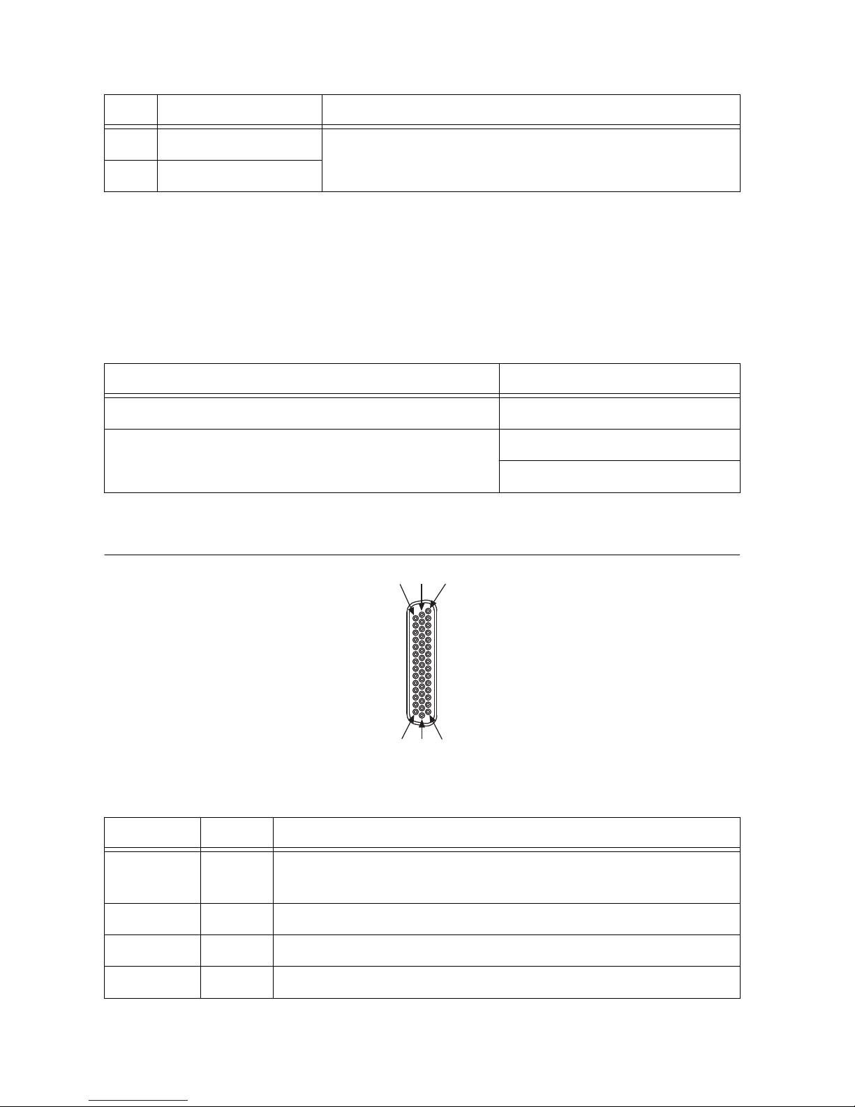
Table 5. USB 3.0 Port Pin Descriptions (Continued)
Pin Signal Name Signal Description
8 StdA_SSTX- SuperSpeed transmitter differential pair
9 StdA_SSTX+
Digital I/O
The 44-pin Digital I/O port on the IC-3121 offers 8 isolated inputs, 8 isolated outputs, 2
bidirectional differential inputs (RS-422) or single-ended input lines that can be used with a
quadrature encoder, and 8 bidirectional TTL lines. The Digital I/O port can be connected to
any appropriate shielded device or connector block using a shielded cable.
NI recommends the following digital I/O cables for the IC-3121.
Cable Part Number
44-pin D-sub male to pigtail cable 156083-03 for 3 meter cable
44-pin D-sub male to 44-position D-sub female cable 156084-03 for 3 meter cable
156084-0R5 for 0.5 meter cable
Refer to the following image and table for pin locations and descriptions.
Figure 9. 44-pin Digital I/O Connector Pin Locations
15
30
44
1
16
31
Table 6. Digital I/O Pin Descriptions
Pin Number Signal Description
1 Diff 0+ Bidirectional RS-422 I/O (positive side), or quadrature encoder
phase A+
2 GND Digital ground reference for TTL and differential I/O
3 TTL 0 Bidirectional TTL I/O
4 TTL 1 Bidirectional TTL I/O
IC-3121 User Manual | © National Instruments | 9
Page 11

Table 6. Digital I/O Pin Descriptions (Continued)
Pin Number Signal Description
5 GND Digital ground reference for TTL and differential I/O
6 TTL 2 Bidirectional TTL I/O
7 TTL 3 Bidirectional TTL I/O
8 GND Digital ground reference for TTL and differential I/O
9 Diff 1+ Bidirectional RS-422 I/O (positive side), or quadrature encoder
phase B+
10 V
ISO
Isolated power voltage reference output
11 C
ISO
Common ground reference for isolated inputs and outputs
12 Iso Out 0 General purpose isolated input
13 Iso Out 1 General purpose isolated input
14 C
ISO
Common ground reference for isolated inputs and outputs
15 Iso Out 4 General purpose isolated output
16 Diff 0- Bidirectional RS-422 I/O (negative side), or quadrature encoder
phase A-
17 GND Digital ground reference for TTL and differential I/O
18 TTL 4 Bidirectional TTL I/O
19 TTL 5 Bidirectional TTL I/O
20 GND Digital ground reference for TTL and differential I/O
21 TTL 6 Bidirectional TTL I/O
22 TTL 7 Bidirectional TTL I/O
23 GND Digital ground reference for TTL and differential I/O
24 Diff 1- Bidirectional RS-422 I/O
25 V
ISO
Isolated power voltage reference output
26 C
ISO
Common ground reference for isolated inputs and outputs
27 Iso Out 2 General purpose isolated output
28 Iso Out 3 General purpose isolated output
29 C
ISO
Common ground reference for isolated inputs and outputs
30 Iso Out 5 General purpose isolated output
10 | ni.com | IC-3121 User Manual
Page 12

Table 6. Digital I/O Pin Descriptions (Continued)
Pin Number Signal Description
31 Iso In 0 General purpose isolated input
32 iso In 1 General purpose isolated input
33 C
ISO
Common ground reference for isolated inputs and outputs
34 Iso In 2 General purpose isolated input
35 Iso In 3 General purpose isolated input
36 C
ISO
Common ground reference for isolated inputs and outputs
37 Iso In 4 General purpose isolated input
38 Iso In 5 General purpose isolated input
39 C
ISO
Common ground reference for isolated inputs and outputs
40 Iso In 6 General purpose isolated input
41 Iso In 7 General purpose isolated input
42 C
ISO
Common ground reference for isolated inputs and outputs
43 Iso Out 6 General purpose isolated output
44 Iso Out 7 General purpose isolated output
Wiring an Isolated Input
You can wire an isolated input to a sourcing output device.
Caution Do not allow the voltage on the isolated inputs to exceed 30 VDC. Doing
so will damage the IC-3121.
Figure 10. Connecting an Isolated Input to a Sourcing Output Device
V
REF
C
ISO
Industrial Controller
Input
Sourcing
Output
Device
Current
Limiter
Power Supply
+
–
IC-3121 User Manual | © National Instruments | 11
Page 13

Wiring an Isolated Output
The digital isolated output circuits source current to external loads.
When an inductive load, such as a relay or solenoid, is connected to an output, a large counterelectromotive force may occur at switching time due to energy stored in the inductive load.
This flyback voltage can damage the outputs and the power supply.
To limit flyback voltages at the inductive load, install a flyback diode across the load. Mount
the flyback diode as close to the load as possible. Use this protection method if you connect
any of the isolated outputs on the IC-3121 to an inductive load.
The following image shows an example of an isolated output wired to an external load with a
flyback diode installed across the load.
Caution Do not draw more than 35 mA from each isolated output when V
ISO
is
5 V. Do not draw more than 80 mA from each isolated output when V
ISO
is 24 V.
Figure 11. Connecting an Isolated Output to an External Load
Digital Output
External Flyback
Diode for
Inductive Loads
V
ISO
C
ISO
V
CC
Industrial Controller
Load
Overcurrent
Protection Circuit
Connecting to Differential I/O
The IC-3121 accepts differential (RS-422) line driver inputs. Each of the two differential I/O
can be configured as an output. Use shielded cables for all applications. Unshielded cables are
more susceptible to noise and can corrupt signals.
12 | ni.com | IC-3121 User Manual
Page 14

Figure 12. Quadrature Encoder/RS-422 Input/Output Circuit
+
–
Diff I/O 0–
Diff I/O 0+
Diff I/O 1–
Diff I/O 1+
+3.3 V
+
–
10 kΩ 10 kΩ 10 kΩ 10 kΩ
EN
EN
7.5 kΩ 7.5 kΩ 7.5 kΩ
7.5 kΩ
Figure 13. Connecting Differential Line Drivers
Diff In 0+
Diff In 0–
Phase A
Phase A
Diff In 1+
Diff In 1–
Phase B
Phase B
External Device Industrial Controller
Twisted Pair
Twisted Pair
+
–
+
–
IC-3121 User Manual | © National Instruments | 13
Page 15

Figure 14. Connecting Single-Ended Line Drivers
Diff In 0+
Diff In 0–
Phase A
Twisted Pair
Twisted Pair
Diff In 1+
Diff In 1–
Phase B
External Device Industrial Controller
+
–
+
–
TTL I/O
The following image shows the circuit for a bidirectional TTL I/O.
Figure 15. TTL Input/Output Circuit
100 Ω
TTL_OUT
TTL_OE
TTL_IN
10 kΩ
FB
TTL I/O
LED Indicators
The IC-3121 provides the following LED indicators.
14 | ni.com | IC-3121 User Manual
Page 16

Figure 16. LED Indicators
RESET
DIGITAL
I
/O
1
0
/
1
00
/
1000
ACT/
LINK
USER1
USER2
PWR/
FAULT
STATUS
0
1
USER1
USER2
PWR/
FAULT
STATUS
IC-3121
Industrial Controller
The following table describes the LEDs and indications.
IC-3121 User Manual | © National Instruments | 15
Page 17

Table 7. LED Indications
LED LED
Color
LED State Indication
STATUS Yellow OFF The IC-3121 initialized successfully and is ready
for use.
2 blinks (RT only) There is no software installed, which is
the out-of-box state, or the IC-3121 has detected
an error in its software. The device has
automatically started up into safe mode. This
usually occurs when an attempt to upgrade the
software is interrupted or if system files are
deleted from the IC-3121. Reinstall software on
the IC-3121.
3 blinks (RT only) The IC-3121 has booted into safe mode.
Refer to the Safe Mode section for information
about the safe mode state.
4 blinks (RT only) The IC-3121 has experienced two
consecutive software exceptions. The IC-3121
automatically restarts after an exception. After the
second exception, the IC-3121 remains in the
exception state, alerting you to resolve the
problem. Reinstall software on the IC-3121 or
contact NI for assistance. Refer to the IC-3121
Getting Started Guide for information about
installing software on the IC-3121.
Continuous
blinking
(RT only) The IC-3121 has not booted into NI
Linux Real-Time. The controller either booted into
an unsupported operating system, was interrupted
during the boot process, or detected an
unrecoverable software error.
Solid (RT only) The IC-3121 is booting up.
(Windows only) An internal drive is being
accessed.
16 | ni.com | IC-3121 User Manual
Page 18

Table 7. LED Indications (Continued)
LED LED
Color
LED State Indication
PWR/
FAULT
— OFF The IC-3121 is OFF. This is not an indication of
whether power is applied or not.
Green Solid The IC-3121 is operating normally and is properly
powered on.
Red Blinking The IC-3121 power-up sequence failed.
USER1/
USER2
Green/
Yellow
— User-controlled LEDs that can be controlled using
the NI System Configuration API.
Related Information
Safe Mode on page 18
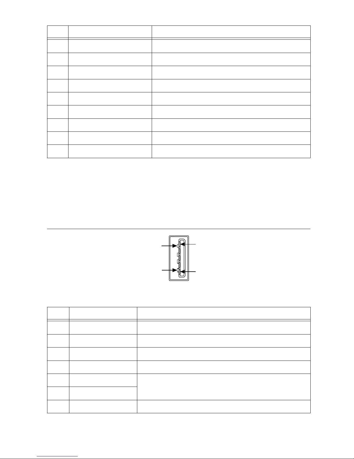
Ethernet LEDs
The Gigabit Ethernet port has the following LEDs.
Figure 17. LEDs for the Gigabit Ethernet Port
1
2
1. Activity/Link LED
2. Speed LED
Table 8. Ethernet LED Indications
LED Status Indication
Activity/Link
Unlit No link has been established
Solid A link has been established
Blinking Activity on the link
Speed
OFF No link, or 10 Mbps link
Green 100 Mbps link
Amber 1,000 Mbps link
IC-3121 User Manual | © National Instruments | 17
Page 19

Using the RESET Button
Pressing the RESET button resets the processor and reboots the system.
Figure 18. RESET Button Locations
SYSTEM
12-24 V
C V
ISO
5-24 V
1
C
ISO
V
ISO
1. RESET Button
(RT only) Troubleshooting Network Connectivity
Use the RESET button to troubleshoot network connectivity.
1. Hold the RESET button for 5 seconds, and then release it to boot the IC-3121 into safe
mode.
2. After booting the controller into safe mode, hold the RESET button again for 5 seconds to
enable IP reset, which resets the network adapter to its default configuration.
Safe Mode
When you boot the IC-3121 into safe mode, it launches only the services necessary for
updating its configuration and installing software. To resume normal operations, press the
RESET button for less than 5 seconds.
IP Reset
Use IP reset to reset the TCP/IP settings when moving the system from one subnet to another
or when the current TCP/IP settings are invalid.
When the IC-3121 is in the IP reset state, the IP address of the network port resets to DHCP or
a link-local address. You can then set up a new network configuration for the IC-3121 from a
18 | ni.com | IC-3121 User Manual
Page 20

development machine on the same subnet, or you can connect the IC-3121 directly to the
development computer.
Note By default, the target automatically attempts to connect to the network using
DHCP. If the target is unable to initiate a DHCP connection, the target connects to
the network with a link-local IP address (169.254.x.x).
Software Options
Use the following software to develop applications with the IC-3121. Refer to the IC-3121
Getting Started Guide for information about installing software.
• NI Industrial Controller Device Drivers 15.5 or later driver software.
• One of the following options for developing machine vision applications:
– LabVIEW 2014 SP1 or later, LabVIEW Real-Time 2014 SP1 or later, the NI Vision
Development Module 2015 SP1 or later.
– NI Vision Builder for Automated Inspection (Vision Builder AI) 2015 or later.
• Software for using and reconfiguring the IC-3121 FPGA. Different configurations are
referred to as hardware personalities, and are defined by bitfiles. NI Industrial Controller
Device Drivers include a reconfigurable I/O personality that you can use out of the box.
Install the following software if you need to compile a custom personality for your
application:
– LabVIEW 2014 SP1 or later and LabVIEW FPGA Module 2014 SP1 or later—You
must install the LabVIEW FPGA Module to reconfigure the default personality of
the IC-3121 FPGA.
BIOS Configuration and System Recovery
You can change the configuration settings for the IC-3121 in the BIOS setup utility. The BIOS
is the low-level interface between the hardware and PC software that configures and tests your
hardware when you boot the system. The BIOS setup utility includes menus for configuring
settings and enabling features.
Most users do not need to use the BIOS setup utility. The system ships with default settings
that work well for most configurations.
Entering BIOS Setup
Complete the following steps to start the BIOS setup program.
1. Connect a monitor to the VGA connector on the IC-3121.
2. Connect a USB keyboard to one of the USB ports on the IC-3121.
3. While holding down the <Delete> key, power on or reboot the IC-3121.
The IC-3121 will enter the BIOS setup program and display the Main menu.
IC-3121 User Manual | © National Instruments | 19
Page 21

BIOS Keyboard Navigation
Use the following keys to navigate through the BIOS setup:
• Left, right, up, and down arrows—Use these keys to move between different setup
menus. Press <Esc> to exit a submenu. Be sure number lock is off to use the numeric
keypad arrows.
• <Enter>—Use this key to either open a submenu or display all available settings for the
highlighted configuration option.
• <Esc>—Use this key to return to a parent menu of a submenu or cancel an outstanding
selection. At the main menu, use this key to exit the BIOS setup.
• <+> and <->—Use these keys to cycle between all available settings.
• <Tab>—Use this key to select time and date fields. When entering date and time and date
information, you can also use the number keys to enter the time and date directly.
• <F9>—Use this key to load the optimal default values for BIOS configuration settings.
The optimal default values are the same as the shipping configuration default values.
Press <F1> from any root menu to display more information about navigating the BIOS setup
program.
Menu items listed in blue are changeable; menu items in gray are not changeable. A blue
triangle next to a menu item indicates that the menu item contains a submenu.
Main Menu
The most commonly accessed and modified BIOS settings are in the Main setup menu.
• System Date—Changes the system date. The system date setting is stored in a batterbacked real-time clock. You can also change this setting from within MAX or Vision
Builder AI.
• System Time—Changes the system time. The system time setting is stored in a batterybacked real-time clock. You can also change this setting from within MAX or Vision
Builder AI.
Advanced Menu
This menu contain BIOS settings that normally do not require modification. If you have
specific problems such as unbootable disks or resource conflicts, you may need to examine
these settings.
The Advanced setup menu includes the following submenus:
• Power/Wake Configuration
• Serial Port Configuration
• SATA Configuration
• USB Configuration
20 | ni.com | IC-3121 User Manual
Page 22

Power/Wake Configuration Submenu
Use this submenu to apply alternate configurations to the power features of the chipset and
controller. Normally, you do not need to modify these settings, as the factory default settings
provide the most compatible and optimal configuration possible.
• Restore After Power Loss—Specify what state to go to when power is reapplied after a
power failure.
Serial Port Configuration Submenu
Use this submenu to view the serial port configuration.
• RS485/RS232 Select—This setting selects the transceiver mode between RS-232 and
RS-485. The default value is RS485.
• RS-485 Configuration—Use this menu to configure the RS-485/422 wire-mode. The
default value is Auto.
Related Information
RS-485/422/232 Serial Port on page 6
SATA Configuration Submenu
Use this submenu to apply custom configurations to the processor of the IC-3121. Normally,
you do not need to modify these settings, as the factory default settings provide the most
compatible and optimal configuration possible.
• SATA Controller(s)—Enables or disables the SATA controller. The default is Enabled.
USB Configuration Submenu
Use the submenu to apply alternate configurations to the USB ports. Normally, you do not
need to modify these settings, as the factory default settings provide the most compatible and
optimal configuration possible.
• Legacy USB Support—Specifies whether or not legacy USB support is enabled. Legacy
USB support refers to the ability to use a USB keyboard and mouse during system boot or
in a legacy operating system such as DOS. The default is Enabled.
• Overcurrent Reporting—Enables or disables operating system notifications of USB
overcurrent events. The default is Disabled.
• Transfer Timeout—Specifies the number of seconds the POST waits for a USB mass
storage device to start. The default is 20 seconds.
• Device Reset Timeout—Specifies the maximum amount of time a device can take to
properly report itself during the POST. The default value is Auto. Alternatively, the
Manual override setting can be used to support slow USB devices.
• Mass Storage Devices—When USB storage is connected to the device, this menu lists
each USB drive. You can set the emulation type of the USB storage. The options include
Auto, Floppy, Forced FDD, Hard Disk, and CD-ROM. The default is Auto.
Boot Menu
This screen displays the boot order of devices associated with the IC-3121. The BIOS
proceeds down the Boot priority order list in search of a bootable device. Devices under the
IC-3121 User Manual | © National Instruments | 21
Page 23

Excluded from boot order list will not be used for booting. If the BIOS fails to find any
bootable device, an error message is displayed.
The Boot setup menu includes the following submenus:
• Boot Settings Configuration—Use this setting to access the Boot Settings Configuration
submenu.
• PXE Network Boot—This setting specifies whether or not the PXE network boot agent is
enabled. When this setting is enabled, the Intel Boot Agent is displayed in the Boot
Option Priorities menu, allowing you to boot from a PXE server on the local subnet.
Note that the Intel Boot Agent device names are preceded by IBA GE Slot in the Boot
Option Priorities menu. The system must be restarted for this setting to take effect. The
default value is Disabled.
• Boot Option Priorities—These setting specify the order in which the BIOS checks for
bootable devices, including the local hard disk drive, removable devices such as USB
flash disk drives or USB CD-ROM drives, or the PXE network boot agent. The BIOS
will first attempt to boot from the device associated with Boot Option #1, followed by
Boot Option #2 and Boot Option #3. If multiple boot devices are not present, the BIOS
setup utility will not display all of these configuration options. To select a boot device,
press <Enter> on the desired configuration on the desired configuration option and select
a boot device from the resulting menu. You can also disable certain boot devices by
selecting Disabled.
Note Only one device of a given type will be shown in this list. If more than one
device of that same type exists, use the Device BBS Priorities submenus to re-order
the priority of devices of the same type.
Boot Settings Configuration Submenu
• Setup Prompt Timeout—This setting specifies the amount of time the system waits for a
BIOS Setup menu keypress (the <Delete> key) in units of a second. The default value is 1
for a delay of one second.
• Bootup NumLock State—This setting specifies the power-on state of the keyboard
NumLock setting. The default value is On.
Device BBS Priority Submenus
The following submenus will be displayed if one or more bootable devices of the
corresponding type is present:
• Hard Drive BBS Priorities
• CD/DVD ROM Drive BBS Priorities
• Floppy Drive BBS Priorities
• Network Device BBS Priorities
Hard Drive BBS Priorities Submenu
• Boot Option #1, Boot Option #2, Boot Option #3—These settings specify the boot
priority of hard drive devices. The highest priority device is displayed on the main Boot
Option Priorities list. Optionally, each device can also be Disabled if the device should
never be used as a boot device.
22 | ni.com | IC-3121 User Manual
Page 24

CD/DVD ROM Drive BBS Priorities Submenu
• Boot Option #1, Boot Option #2, Boot Option #3—These settings specify the boot
priority of CD/DVD ROM drive devices. The highest priority device is displayed on the
main Boot Option Priorities list. Optionally, each device can also be Disabled if the
device should never be used as a boot device.
Floppy Drive BBS Priorities Submenu
• Boot Option #1, Boot Option #2, Boot Option #3—These settings specify the boot
priority of network devices. The highest priority device is displayed on the main Boot
Option Priorities list. Optionally, each device can also be Disabled if the device should
never be used as a boot device.
Network Device BBS Priorities Submenu
• Boot Option #1, Boot Option #2, Boot Option #3—These settings specify the boot
priority of network devices. The highest priority device is displayed on the main Boot
Option Priorities list. Optionally, each device can also be Disabled if the device should
never be used as a boot device.
Save & Exit Menu
The Save & Exit setup menu includes all available options for exiting, saving, and loading the
BIOS default configuration. You can also press <F9> to load BIOS default settings and <F10>
to save changes and exit setup.
The Save & Exit setup menu includes the following settings:
• Save Changes and Reset—Any changes made to BIOS settings are stored in NVRAM.
The setup utility then exits and reboots the controller.
• Discard Changes and Reset—Any changes made to BIOS settings during this session of
the BIOS setup utility since the last save are discarded. The setup utility then exits and
reboots the controller. The <Esc> key can also be used to select this option.
• Save Changes—Changes made to BIOS settings during this session are committed to
NVRAM. The setup utility remains active, allowing further changes.
• Discard Changes—Any changes made to BIOS settings during this session of the BIOS
setup utility since the last save are discarded. The BIOS setup continues to be active.
• Restore Factory Defaults—This option restores all BIOS settings to the factory default.
This option is useful if the controller exhibits unpredictable behavior due to an incorrect
or inappropriate BIOS setting. Any nondefault settings are also restored to their factory
defaults. The <F9> key can also be used to select this option.
• Save as User Defaults—This option saves a copy of the current BIOS settings as the User
Defaults. This option is useful for preserving custom BIOS setup configurations.
• Boot Override—This option lists all possible bootable devices and allows the user to
override the Boot Option Priorities list for the current boot. If no changes have been
made to the BIOS setup options, the system will continue booting to the selected device
without first rebooting. If BIOS setup options have been changed and saved, a reboot is
required and the boot override selection will not be valid.
IC-3121 User Manual | © National Instruments | 23
Page 25

Restoring the NI Linux Real-Time Operating System
Complete the following steps to restore the NI Linux Real-Time operating system to its factory
default condition. These steps do not restore the BIOS settings to factory default. Use the
Restore Defaults option in the Save & Exit Menu of the BIOS setup utility to restore the BIOS
settings.
Caution Restoring the operating system erases the contents of the hard drive. Back
up any files you want to keep before restoring the hard drive.
1. Start the IC-3121 in safe mode. To start in safe mode, apply power, turn on the device,
press the RESET button for more than 5 seconds, then release the button.
2. Launch NI MAX on the development computer.
3. In the MAX configuration tree, expand Remote Systems.
4. Right-click the name of the IC-3121 you want to restore and select Format Disk.
5. Enter the username and password for the device. By default, the username is admin and
the password field is blank.
6. Click Format.
7. After formatting is complete, a confirmation dialog window appears. Click Close.
8. Refer to the IC-3121 Getting Started Guide for information about installing software and
configuring the device.
Related Information
Safe Mode on page 18
Restoring the Windows Operating System
You can restore the Windows operating system on the hard drive of the IC-3121 from the
reinstallation DVD shipped with device.
Note Restoring the operating system erases the contents of the hard drive. Back up
any files you want to keep before restoring the hard drive.
Creating a Bootable USB Flash Drive
You can create a bootable USB flash drive from the reinstallation DVD if you do not have a
USB DVD drive to connect to the IC-3121. The USB flash drive must be at least 8 GB. Ensure
the USB flash drive appears as a Removable Drive in Windows. Avoid using drives that
appear as Fixed Disk drives. Complete the following steps to prepare the USB flash drive for
recovery.
Note If you have an external USB DVD drive, you can use the external DVD drive
to restore Windows without creating a bootable USB flash drive. Proceed to the next
section if you are using an external DVD drive.
1. Insert the USB flash drive into a computer with a DVD drive running Windows, and wait
for the flash drive to be recognized.
2. Open a command prompt as an administrator.
24 | ni.com | IC-3121 User Manual
Page 26

3. Type diskpart.exe and press <Enter>.
4. Type list disk and press <Enter>.
5. Identify the drive number that corresponds to the USB flash drive.
6. Type select disk x, where x is the drive number of the USB flash drive, and press
<Enter>. For example, in the following image, the USB flash drive is disk number 5. The
command is select disk 5.
Caution Following this process will delete all data on the USB flash drive.
7. Type clean and press <Enter>. This command deletes all data from the USB flash drive.
8. Type create partition primary and press <Enter>.
9. Type active and press <Enter>
10. Type format fs=ntfs quick and press <Enter> to format the USB flash drive.
11. Type assign letter free volume letter, where free volume letter is a
letter not currently associated with any disk drives. For example, assign letter K.
12. Copy the contents of the reinstallation DVD to the root of the USB flash drive.
The USB flash drive is now bootable and will install Windows.
Reinstalling Windows
Complete the following steps to use the recovery media to install Windows.
1. Connect the bootable USB flash drive to one of the USB ports on the IC-3121. Or
connect an external DVD drive to one of the USB ports on the IC-3121 and insert the
recovery DVD into the external drive.
2. Connect a USB hub to the other USB port on the IC-3121. Connect a keyboard and
mouse to the USB hub. If a USB hub is not available, the keyboard can be used to
navigate the recovery software.
3. Power on the IC-3121.
4. Press the <F10> key on the keyboard.
IC-3121 User Manual | © National Instruments | 25
Page 27

5. Select the bootable USB flash drive or the DVD drive.
6. Press any key to boot from the recovery media.
7. Follow the on-screen instructions to format the hard drive and install the operating
system.
After restoring the operating system, reinstall any software and drivers onto the IC-3121.
Mounting the IC-3121
This section provides information for creating a custom mount for the IC-3121. If you do not
want to create a custom mount, a panel and DIN rail mount kit for the IC-3121 is available
from National Instruments (part number 781740-01).
Caution If you choose not to mount the IC-3121 on a DIN rail or flat surface, do
not position the IC-3121 with the heat sinks resting on any surface. Doing so may
cause the IC-3121 device to overheat. Refer to the IC-3121 Specifications for
temperature specifications.
The following figures provide dimensional drawings and clearance information for the
IC-3121.
26 | ni.com | IC-3121 User Manual
Page 28

Figure 19. Front View with Dimensions in inches [millimeters]
23.35 mm
(0.919 in.)
20.37 mm
(.802 in.)
32.48 mm
(1.279 in.)
16.93 mm
(0.667 in.)
17.11 mm
(0.674 in.)
26.78 mm
(1.054 in.)
27.56 mm
(1.085 in.)
21.19 mm
(0.834 in.)
15.07 mm
(0.593 in.)
38.75 mm
(1.526 in.)
9.51 mm
(0.374 in.)
40.77 mm
(1.605 in.)
26.7 mm
(1.051 in.)
24.17 mm
(0.951 in.)
17.21 mm
(0.678 in.)
60.96 mm (2.400 in.)
24.71 mm
(0.973 in.)
IC-3121
Industrial Controller
IC-3121 User Manual | © National Instruments | 27
Page 29

Figure 20. Back View with Dimensions in inches [millimeters]
23.46 mm
(0.924 in.)
54.48 mm
(2.145 in.)
23.24 mm
(0.915 in.)
37.50 mm
(1.476 in.)
19.41 mm
(0.764 in.)
24.46 mm
(0.963 in.)
25.92 mm
(1.020 in.)
10.58 mm
(0.417 in.)
28 | ni.com | IC-3121 User Manual
Page 30

Figure 21. Side View with Dimensions in inches [millimeters]
130.38 mm
(5.133 in.)
108.47 mm (4.270 in.)
3.80 mm
(0.150 in.)
104.67 mm (4.121 in.)
IC-3121 User Manual | © National Instruments | 29
Page 31

Figure 22. Bottom View with Dimensions in inches [millimeters]
2X 6–32
6.35 mm (0.250 in.)
11.43 mm
(0.450 in.)
11.43 mm
(0.450 in.)
65.19 mm
(2.566 in.)
65.19 mm
(2.566 in.)
38.10 mm
(1.50 in.)
Securing the IC-3121 to a Mount
1. Align the screw holes of the mounting bracket with the two holes on the back of the
IC-3121.
2. Insert two 6-32 screws and tighten them until they are secure (3.5 in-lb). Make sure the
heads of the screws are flush with the mounting bracket.
Clearance Requirements
The IC-3121 installation must meet the following space and cabling clearance requirements
for optimum cooling:
• Allow 76.2 mm (3.0 in.) on the top and bottom of the IC-3121 for air circulation.
• Allow 50.8 mm (2.0 in.) on the sides of the IC-3121 for air circulation.
• Allow enough space in front of the IC-3121 to connect cables.
30 | ni.com | IC-3121 User Manual
Page 32

Figure 23. Clearance Requirements for the IC-3121
50.8 mm
(2.00 in.)
50.8 mm
(2.00 in.)
76.2 mm
(3.00 in.)
76.2 mm
(3.00 in.)
RESET
DIGITAL I/O
10/100/
1000
ACT/
LINK
USER1
USER2
PWR/
FAULT
STATUS
0
1
IC-3121
Industrial Controller
Where to Go Next
The following documents and resources contain information you may find helpful as you use
the IC-3121 in an application. Refer to the National Instruments Product Manuals Library at
ni.com/manuals for the most recent versions of product documentation.
• IC-3121 Specifications—Contains detailed specifications for the IC-3121.
• IC-3121 Getting Started Guide—Explains how to install and configure the software
necessary to use the IC-3121, and how to get started using the hardware.
• NI CVS I/O Accessory User Manual—Contains installation and operation instructions for
the NI CVS I/O Accessory.
IC-3121 User Manual | © National Instruments | 31
Page 33

Worldwide Support and Services
The NI website is your complete resource for technical support. At ni.com/support, you have
access to everything from troubleshooting and application development self-help resources to
email and phone assistance from NI Application Engineers.
Visit ni.com/services for NI Factory Installation Services, repairs, extended warranty, and
other services.
Visit ni.com/register to register your NI product. Product registration facilitates technical
support and ensures that you receive important information updates from NI.
A Declaration of Conformity (DoC) is our claim of compliance with the Council of the
European Communities using the manufacturer’s declaration of conformity. This system
affords the user protection for electromagnetic compatibility (EMC) and product safety. You
can obtain the DoC for your product by visiting ni.com/certification. If your product supports
calibration, you can obtain the calibration certificate for your product at ni.com/calibration.
NI corporate headquarters is located at 11500 North Mopac Expressway, Austin, Texas,
78759-3504. NI also has offices located around the world. For telephone support in the United
States, create your service request at ni.com/support or dial 1 866 ASK MYNI (275 6964). For
telephone support outside the United States, visit the Worldwide Offices section of ni.com/
niglobal to access the branch office websites, which provide up-to-date contact information,
support phone numbers, email addresses, and current events.
Refer to the NI Trademarks and Logo Guidelines at ni.com/trademarks for information on NI trademarks. Other product and
company names mentioned herein are trademarks or trade names of their respective companies. For patents covering NI
products/technology, refer to the appropriate location: Help»Patents in your software, the patents.txt file on your media, or the
National Instruments Patent Notice at ni.com/patents. You can find information about end-user license agreements (EULAs)
and third-party legal notices in the readme file for your NI product. Refer to the Export Compliance Information at ni.com/
legal/export-compliance for the NI global trade compliance policy and how to obtain relevant HTS codes, ECCNs, and other
import/export data. NI MAKES NO EXPRESS OR IMPLIED WARRANTIES AS TO THE ACCURACY OF THE INFORMATION
CONTAINED HEREIN AND SHALL NOT BE LIABLE FOR ANY ERRORS. U.S. Government Customers: The data contained in
this manual was developed at private expense and is subject to the applicable limited rights and restricted data rights as set forth
in FAR 52.227-14, DFAR 252.227-7014, and DFAR 252.227-7015.
© 2016 National Instruments. All rights reserved.
376111A-01 Apr16
 Loading...