

Page 1

GPIB
Getting Started with
Your GPIB-SCSI-A and
NI-488.2™for Solaris
GPIB-SCSI-A for Solaris
June 2001 Edition
Part Number 320639B-01
Page 2

Support
Worldwide Technical Support and Product Information
ni.com
National Instruments Corporate Headquarters
11500 North Mopac Expressway Austin, Texas 78759-3504 USA Tel: 512 794 0100
Worldwide Offices
Australia 03 9879 5166, Austria 0662 45 79 90 0, Belgium 02 757 00 20, Brazil 011 284 5011,
Canada (Calgary) 403 274 9391, Canada (Montreal) 514 288 5722, Canada (Ottawa) 613 233 5949,
Canada (Québec) 514 694 8521, Canada (Toronto) 905 785 0085, China (Shanghai) 021 6555 7838,
China (ShenZhen) 0755 3904939, Denmark 45 76 26 00, Finland 09 725 725 11, France 01 48 14 24 24,
Germany 089 741 31 30, Greece 30 1 42 96 427, Hong Kong 2645 3186, India 91805275406,
Israel 03 6120092, Italy 02 413091, Japan 03 5472 2970, Korea 02 596 7456, Malaysia 603 9596711,
Mexico 5 280 7625, Netherlands 0348 433466, New Zealand 09 914 0488, Norway 32 27 73 00,
Poland 0 22 528 94 06, Portugal 351 1 726 9011, Singapore 2265886, Spain 91 640 0085,
Sweden 08 587 895 00, Switzerland 056 200 51 51, Taiwan 02 2528 7227, United Kingdom 01635 523545
For further support information, see the Technical Support Resources appendix. To comment on the
documentation, send e-mail to techpubs@ni.com.
Copyright © 1993, 2001 National Instruments Corporation. All rights reserved.
Page 3

Important Information
Warranty
The GPIB-SCSI-A is warranted against defects in materials and workmanship for a period of two years from the date of shipment, as evidenced
by receipts or other documentation. National Instruments will, at its option, repair or replace equipment that proves to be defective during the
warranty period. This warranty includes parts and labor.
The media on which you receive National Instruments software are warranted not to fail to execute programming instructions, due to defects
in materials and workmanship, for a period of 90 days from date of shipment, as evidenced by receipts or other documentation. National
Instruments will, at its option, repair or replace software media that do not execute programming instructions if National Instruments receives
notice of such defects during the warranty period. National Instruments does not warrant that the operation of the software shall be
uninterrupted or error free.
A Return Material Authorization (RMA) number must be obtained from the factory and clearly marked on the outside of the package before
any equipment will be accepted for warranty work. National Instruments will pay the shipping costs of returning to the owner parts which are
covered by warranty.
National Instruments believes that the information in this document is accurate. The document has been carefully reviewed for technical
accuracy. In the event that technical or typographical errors exist, National Instruments reserves the right to make changes to subsequent
editions of this document without prior notice to holders of this edition. The reader should consult National Instruments if errors are suspected.
In no event shall National Instruments be liable for any damages arising out of or related to this document or the information contained in it.
XCEPT AS SPECIFIED HEREIN,NATIONAL INSTRUMENTS MAKES NO WARRANTIES, EXPRESS OR IMPLIED, AND SPECIFICALLY DISCLAIMS ANY WARRANTY OF
E
MERCHANTABILITY OR FITNESS FOR A PARTICULAR PURPOSE
NATIONAL INSTRUMENTS SHALL BE LIMITED TO THE AMOUNT THERETOFORE PAID BY THE CUSTOMER.NATIONAL INS TRUMENTS WILL NOT BE LIABLE FOR
DAMAGES RESULTING FROM LOSS OF DATA
. This limitation of the liability ofNational Instruments will apply regardless of the form of action, whether in contract or tort, including
THEREOF
negligence. Any action against National Instruments must be brought within one year after the cause of action accrues. National Instruments
shall not be liable for any delay in performance due to causes beyond its reasonable control. The warranty provided herein does not cover
damages, defects, malfunctions, or service failures caused by owner’s failure to follow the National Instruments installation, operation, or
maintenance instructions; owner’s modification of the product; owner’s abuse, misuse, or negligent acts; and power failure or surges, fire,
flood, accident, actions of third parties, or other events outside reasonable control.
, PROFITS, USE OF PRODUCTS, OR INCIDENTAL OR CONSEQUENTIAL DAMAGES, EVEN IF ADVISED OF THE POSSIBILITY
Copyright
Under the copyright laws, this publication maynot bereproduced or transmitted in any form, electronic or mechanical, including photocopying,
recording, storing in an information retrieval system, or translating, in whole or in part, without the prior written consent of National
Instruments Corporation.
Trademarks
National Instruments™,NI™, NI-488™, NI-488.2™, NI-488.2M™, and ni.com™are trademarks of National Instruments Corporation.
Product and company names mentioned herein are trademarks or trade names of their respective companies.
.CUSTOMER’S RIGHT TO RECOVER DAMAGES CAUSED BY FAULT OR NEGLIGENCE ON THE PART OF
Patents
The product described in this manual may be protected by one or more U.S. patents, foreign patents, or pending applications.
U.S. Patent No(s) 5,974,541, 5,964,892, 5,958,028, 5,987,530, 6,073,205. Other U.S. and International patents pending.
WARNING REGARDING USE OF NATIONAL INSTRUMENTS PRODUCTS
(1) NATIONAL INSTRUMENTS PRODUCTS ARE NOT DESIGNED WITH COMPONENTS AND TESTING FOR A LEVEL OF
RELIABILITY SUITABLE FOR USE IN OR IN CONNECTION WITH SURGICAL IMPLANTS OR AS CRITICAL COMPONENTS IN
ANY LIFE SUPPORT SYSTEMS WHOSE FAILURE TO PERFORM CAN REASONABLY BE EXPECTED TO CAUSE SIGNIFICANT
INJURY TO A HUMAN.
(2) IN ANY APPLICATION, INCLUDING THE ABOVE, RELIABILITY OF OPERATION OF THE SOFTWARE PRODUCTS CAN BE
IMPAIRED BY ADVERSE FACTORS, INCLUDING BUT NOT LIMITED TO FLUCTUATIONS IN ELECTRICAL POWER SUPPLY,
COMPUTER HARDWARE MALFUNCTIONS, COMPUTER OPERATING SYSTEM SOFTWARE FITNESS, FITNESS OF COMPILERS
AND DEVELOPMENT SOFTWARE USED TO DEVELOP AN APPLICATION, INSTALLATION ERRORS, SOFTWARE AND
HARDWARE COMPATIBILITY PROBLEMS, MALFUNCTIONS OR FAILURES OF ELECTRONIC MONITORING OR CONTROL
DEVICES, TRANSIENT FAILURES OF ELECTRONIC SYSTEMS (HARDWARE AND/OR SOFTWARE), UNANTICIPATED USES OR
MISUSES, OR ERRORS ON THE PART OF THE USER OR APPLICATIONS DESIGNER (ADVERSE FACTORS SUCH AS THESE ARE
HEREAFTER COLLECTIVELY TERMED “SYSTEM FAILURES”). ANY APPLICATION WHERE A SYSTEM FAILURE WOULD
CREATE A RISK OF HARM TO PROPERTY OR PERSONS (INCLUDING THE RISK OF BODILY INJURY AND DEATH) SHOULD
NOT BE RELIANT SOLELY UPON ONE FORM OF ELECTRONIC SYSTEM DUE TO THE RISK OF SYSTEM FAILURE. TO AVOID
DAMAGE, INJURY, OR DEATH, THE USER OR APPLICATION DESIGNER MUST TAKE REASONABLY PRUDENT STEPS TO
PROTECT AGAINST SYSTEM FAILURES, INCLUDING BUT NOT LIMITED TO BACK-UP OR SHUT DOWN MECHANISMS.
BECAUSE EACH END-USER SYSTEM IS CUSTOMIZED AND DIFFERS FROM NATIONAL INSTRUMENTS' TESTING
PLATFORMS AND BECAUSE A USER OR APPLICATION DESIGNER MAY USE NATIONAL INSTRUMENTS PRODUCTS IN
COMBINATION WITH OTHER PRODUCTS IN A MANNER NOT EVALUATED OR CONTEMPLATED BY NATIONAL
INSTRUMENTS, THE USER OR APPLICATION DESIGNER IS ULTIMATELY RESPONSIBLE FOR VERIFYING AND VALIDATING
THE SUITABILITY OF NATIONAL INSTRUMENTS PRODUCTS WHENEVER NATIONAL INSTRUMENTS PRODUCTS ARE
INCORPORATED IN A SYSTEM OR APPLICATION, INCLUDING, WITHOUT LIMITATION, THE APPROPRIATE DESIGN,
PROCESS AND SAFETY LEVEL OF SUCH SYSTEM OR APPLICATION.
Page 4

Compliance
FCC/Canada Radio Frequency Interference Compliance*
Determining FCC Class
The Federal Communications Commission (FCC) has rules to protect wireless communications from interference. The FCC
places digital electronics into two classes. These classes are known as Class A (for use in industrial-commercial locations only)
or Class B (for use in residential or commercial locations). Depending on where it is operated, this product could be subject to
restrictions in the FCC rules. (In Canada, the Department of Communications (DOC), of Industry Canada, regulates wireless
interference in much the same way.)
Digital electronics emit weak signals during normal operation that can affect radio, television, or other wireless products. By
examining the product you purchased, you can determine the FCC Class and therefore which of the two FCC/DOC Warnings
apply in the following sections. (Some products may not be labeled at all for FCC; if so, the reader should then assume these are
Class A devices.)
FCC Class A products only display a simple warning statement of one paragraph in length regarding interference and undesired
operation. Most of our products are FCC Class A. The FCC rules have restrictions regarding the locations where FCC Class A
products can be operated.
FCC Class B products display either a FCC ID code, starting with the letters EXN,
or the FCC Class B compliance mark that appears as shown here on the right.
Consult the FCC web site
http://www.fcc.gov
FCC/DOC Warnings
This equipment generates and uses radio frequency energy and,if not installed and used in strict accordance with the instructions
in this manual and the CE Mark Declaration of Conformity**, may cause interference to radio and television reception.
Classification requirements are the same for the Federal Communications Commission (FCC) and the Canadian Department
of Communications (DOC).
Changes or modifications not expressly approved by National Instruments could void the user’s authority to operate the
equipment under the FCC Rules.
for more information.
Class A
Federal Communications Commission
This equipment has been tested and found to comply with the limits for a Class A digital device, pursuant to part 15 of the FCC
Rules. These limits are designed to provide reasonable protection against harmful interference when the equipment is operated
in a commercial environment. This equipment generates, uses, and can radiate radio frequency energy and, if not installed and
used in accordance with the instruction manual, may cause harmful interference to radio communications. Operation of this
equipment in a residential area is likely to cause harmful interference in which case the user will be required to correct
the interference at his own expense.
Canadian Department of Communications
This Class A digital apparatus meets all requirements of the Canadian Interference-Causing Equipment Regulations.
Cet appareil numérique de la classe A respecte toutes les exigences du Règlement sur le matériel brouilleur du Canada.
Class B
Federal Communications Commission
This equipment has been tested and found to comply with the limits for a Class B digital device, pursuant to part 15 of the
FCC Rules. These limits are designed to provide reasonable protection against harmful interference in a residential installation.
This equipment generates, uses and can radiate radio frequency energy and, if not installed and used in accordance with the
instructions, may cause harmful interference to radio communications. However, there is no guarantee that interference will not
occur in a particular installation. If this equipment does cause harmful interference to radio or television reception, which can
be determined by turning the equipment off and on, the user is encouraged to try to correct the interference by one or more of
the following measures:
• Reorient or relocate the receiving antenna.
• Increase the separation between the equipment and receiver.
• Connect the equipment into an outlet on a circuit different from that to which the receiver is connected.
• Consult the dealer or an experienced radio/TV technician for help.
Page 5

Canadian Department of Communications
This Class B digital apparatus meets all requirements of the Canadian Interference-Causing Equipment Regulations.
Cet appareil numérique de la classe B respecte toutes les exigences du Règlement sur le matériel brouilleur du Canada.
Compliance to EU Directives
Readers in the European Union (EU) must refer to the Manufacturer's Declaration of Conformity (DoC) for information**
pertaining to the CE Mark compliance scheme. The Manufacturer includes a DoC for most every hardware product except for
those bought for OEMs, if also available from an original manufacturer that also markets in the EU, or where compliance is not
required as for electrically benign apparatus or cables.
To obtain the DoC for this product, click Declaration of Conformity at
by product family. Select the appropriate product family, followed by your product, and a link to the DoC appears in Adobe
Acrobat format. Click the Acrobat icon to download or read the DoC.
* Certain exemptions may apply in the USA, see FCC Rules §15.103 Exempted devices,and§15.105(c). Also available in
sections of CFR 47.
** The CE Mark Declaration of Conformity will contain important supplementary information and instructions for the user or
installer.
ni.com/hardref.nsf/
. This website lists the DoCs
Page 6

Conventions
The following conventions are used in this manual:
This icon denotes a note, which alerts you to important information.
This icon denotes a caution, which advises you of precautions to take to
avoid injury, data loss, or a system crash.
bold Bold text denotes the names of light-emitting diodes (LEDs).
italic Italic text denotes variables, emphasis, a cross reference, or an introduction
to a key concept. This font also denotes text that is a placeholder for a word
or value that you must supply.
monospace
Text in this font denotes text or characters that you should enter from the
keyboard, sections of code, programming examples, and syntax examples.
This font is also used for the proper names of disk drives, paths, directories,
programs, subprograms, subroutines, device names, functions, operations,
variables, filenames and extensions, and code excerpts.
Page 7

Contents
Chapter 1
Introduction
What You Need to Get Started ......................................................................................1-1
GPIB Hardware Overview.............................................................................................1-2
NI-488.2 Overview ........................................................................................................1-2
Chapter 2
Installation
Configuring the Hardware .............................................................................................2-1
Configuration Switch Settings for SW1..........................................................2-2
Configuration Switch Settings for SW2..........................................................2-5
Using SCSI Terminating Resistors..................................................................2-6
Connecting the Hardware ..............................................................................................2-8
Step 1. Shut Down the System ........................................................................ 2-9
Step 2. Connect the Cables..............................................................................2-9
Step 3. Switch On Your GPIB-SCSI-A...........................................................2-10
Step 4. Power On Your System....................................................................... 2-10
Installing NI-488.2.........................................................................................................2-10
Configuring the Software with ibconf (Optional)..........................................................2-11
Removing NI-488.2 (Optional)......................................................................................2-11
Chapter 3
Installation Verification
Chapter 4
Using NI-488.2 with Solaris
Introduction to ibic......................................................................................................... 4-1
Programming Considerations ........................................................................................4-2
Appendix A
Troubleshooting and Common Questions
Appendix B
Specifications
© National Instruments Corporation vii GPIB-SCSI-A for Solaris
Page 8

Contents
Appendix C
Technical Support Resources
Glossary
Index
GPIB-SCSI-A for Solaris viii ni.com
Page 9

Introduction
This chapter explains how to use this manual, lists what you need to get
started, and briefly describes the GPIB-SCSI-A and NI-488.2 for Solaris.
What You Need to Get Started
❑
Solarisversion2.5.1orhigherinstalledonyourSunSPARCsystem
❑
One of the following GPIB-SCSI-A boxes:
– 100–120 VAC
– 220–240 VAC
❑
One of the following power cords:
– U.S.A. standard power cord
– U.K. power cord
– Switzerland power cord
– Australian power cord
– Universal European power cord
– North American power cord
1
❑
Standard 50-pin SCSI-1 terminator
❑
Type SCSI-G Cable: GPIB-SCSI-A (50-pin SCSI-1) to Sun SPARC
system (SCSI-2 50-pin)–1m
NI-488.2 for Solaris and GPIB-SCSI-A, Version 2.x CD
❑
❑
Super-user privilege
❑
One of the following shielded GPIB cables, which you can purchase
from National Instruments:
– Type X1 single-shielded cables (1, 2, or 4 m)
– Type X2 double-shielded cables (1, 2, or 4 m)
© National Instruments Corporation 1-1 GPIB-SCSI-A for Solaris
Page 10

Chapter 1 Introduction
Caution
(Type X1 or X2) GPIB cable. Operating this equipment with a non-shielded cable
may interfere with radio and television reception.
To meet FCC emission limits for this device, you must use a shielded
GPIB Hardware Overview
The GPIB-SCSI-A is a high-performance interface product that
transparently handles data transfers between the SCSI and the GPIB.
The GPIB-SCSI-A is actually an 8-bit microcomputer that operates as a
full-function IEEE 488.2/SCSI Controller. It can turn any computer with
a SCSI port into a GPIB Talker/Listener/Controller or it can make any
device on the SCSI bus look like a GPIB device.
The GPIB-SCSI-A has all the software and logic required to implement
the physical and electrical characteristics of the ANSI/IEEE Standard
488.2-1987 and the ANSI Standard X3T9.2. It is able to interpret and
execute commands that you send to it over the GPIB or SCSI ports and
to perform all necessary GPIB-to-SCSI protocol conversions.
Standard GPIB cables can connect the GPIB-SCSI-A with up to 14 devices.
If you need to connect to more than 14 devices, you can add them to your
system using an IEEE 488 extender or expander, such as the National
Instruments GPIB-130, GPIB-120A, or GPIB-140A. Refer to Appendix B,
Specifications, for more information about the GPIB hardware
specifications and recommended operating conditions.
NI-488.2 Overview
NI-488.2 forSolaris consists of a loadable driver and utilities that transform
a Sun SPARC system running Solaris into an IEEE 488.2 (GPIB)
Controller with complete communications and bus management
capabilities.
NI-488.2 includes the following components:
• C language interface
• Software diagnostic utility
• Interactive control utility
• Interactive configuration utility
NI-488.2 supports multiple GPIB-SCSI-A boxes installed in a Sun SPARC
system, and is completely compatible with both IEEE 488 and IEEE 488.2
instruments.
GPIB-SCSI-A for Solaris 1-2 ni.com
Page 11
Installation
2
This chapter describes how to install NI-488.2 for Solaris and how to
configure and connect the GPIB-SCSI-A to your Sun SPARC system.
The NI-488.2 software included in this kit is intended for use with Sun
SPARC systems running Solaris 2.5.1 or higher.
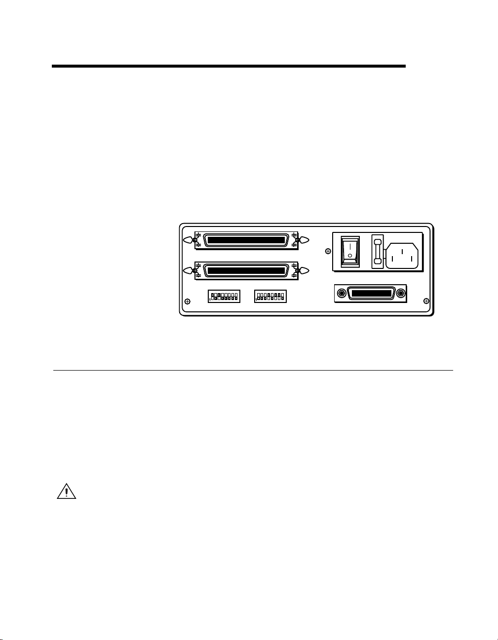
Figure 2-1 shows the rear panel of the GPIB-SCSI-A.
A
B
12345678
O
N
CTS206-8
SW1 SW2
Configuring the Hardware
The hardware configurations of the SCSI ID (Target ID) and the GPIB
primary address must match the software configuration in the system
configuration files and the NI-488.2 software.
The GPIB-SCSI-A is shipped from the factory with a 100-120 V or a
220-240 V power supply. Before you use the GPIB-SCSI-A, verify that
the voltage on the power supply matches the voltage that is supplied in
your area.
Caution
bottom of the unit could damage the unit. Replacement fuses must be the proper type and
rating. See Appendix B, Specifications, for fuse information.
Operating the GPIB-SCSI-A at any voltage other than the one specified on the
SCSI
12345678
O
N
9120
CTS206-8
Figure 2-1.
ON
OFF
9120
GPIB
GPIB-SCSI-A Rear Panel
© National Instruments Corporation 2-1 GPIB-SCSI-A for Solaris
Page 12

Chapter 2 Installation
Note
The only parameters available for configuration with this kit are the SCSI ID and the
GPIB address. Do not change any other switch settings from the factory default settings.
The GPIB-SCSI-A is shipped from the factory configured to operate
in SCSI (S) mode. Optional parity checking on the SCSI port is disabled.
The SCSI ID that the GPIB-SCSI-A responds to is set at 5, and the primary
GPIB address is set at 0. Additionally, the GPIB-SCSI-A kit is shipped
from the factory with a SCSI terminating resistor installed. Depending
on how you connect the GPIB-SCSI-A to your system, you may want
to remove the terminating resistor.
The factory default setting of the GPIB-SCSI-A Target ID is 5. To confirm
that a Target ID of 5 is available in your system, print out the startup
messages from the last time you booted with the following command:
dmesg
Among the startup messages are the devices found on the SCSI bus
and their respective Target ID numbers. If a Target ID of 5 is not available
in your system, select an unused Target ID (a number between 0 and 7)
and set the appropriate switch to that Target ID number (refer to the next
section, Configuration Switch Settings for SW1). Typically, Targets 1 and 3
are used by the internal disks, Target 4 is used by a tape drive (if you have
a tape drive), and Target 0 is used by an external disk drive. Target 7 is
always used by the Sun SPARC system central processing unit.
Configuration Switch Settings for SW1
The DIP switch at location SW1 on the rear panel (see Figure 2-1) is used
to configure the power-on primary GPIB address and SCSI ID of the
GPIB-SCSI-A. Figure 2-2 shows the factory default settings.
12345678
O
N
9120
CTS 206-8
SW1
Figure 2-2. SW1 Default Mode Switch Settings
GPIB-SCSI-A for Solaris 2-2 ni.com
Page 13

Chapter 2 Installation
The default settings of switches 1 through 3 are ON, OFF, ON, respectively,
to select the SCSI ID of 5. Switches 4 through 8 are OFF, indicating that the
GPIB primary address of the GPIB-SCSI-A is 0.
Tables 2-1 and 2-2 show the possible configurations of the eight switches
for SW1 and what each configuration indicates. Factory default settings are
in bold.
Table 2-1. SW1 Configuration Parameters for Switches 1 through 3
Switches
Indication1 2 3
OFF OFF OFF SCSI ID of 0
OFF OFF ON SCSI ID of 1
OFF ON OFF SCSI ID of 2
OFF ON ON SCSI ID of 3
ON OFF OFF SCSI ID of 4
ON OFF ON SCSI ID of 5
ON ON OFF SCSI ID of 6
ON ON ON SCSI ID of 7
Table 2-2. SW1 Configuration Parameters for Switches 4 through 8
Switches
Indication4 5 6 7 8
OFF OFF OFF OFF OFF GPIB Primary Address 0
OFF OFF OFF OFF ON GPIB Primary Address 1
OFF OFF OFF ON OFF GPIB Primary Address 2
OFF OFF OFF ON ON GPIB Primary Address 3
OFF OFF ON OFF OFF GPIB Primary Address 4
OFF OFF ON OFF ON GPIB Primary Address 5
OFF OFF ON ON OFF GPIB Primary Address 6
OFF OFF ON ON ON GPIB Primary Address 7
© National Instruments Corporation 2-3 GPIB-SCSI-A for Solaris
Page 14

Chapter 2 Installation
Table 2-2. SW1 Configuration Parameters for Switches 4 through 8 (Continued)
Switches
Indication4 5 6 7 8
OFF ON OFF OFF OFF GPIB Primary Address 8
OFF ON OFF OFF ON GPIB Primary Address 9
OFF ON OFF ON OFF GPIB Primary Address 10
OFF ON OFF ON ON GPIB Primary Address 11
OFF ON ON OFF OFF GPIB Primary Address 12
OFF ON ON OFF ON GPIB Primary Address 13
OFF ON ON ON OFF GPIB Primary Address 14
OFF ON ON ON ON GPIB Primary Address 15
ON OFF OFF OFF OFF GPIB Primary Address 16
ON OFF OFF OFF ON GPIB Primary Address 17
ON OFF OFF ON OFF GPIB Primary Address 18
ON OFF OFF ON ON GPIB Primary Address 19
ON OFF ON OFF OFF GPIB Primary Address 20
ON OFF ON OFF ON GPIB Primary Address 21
ON OFF ON ON OFF GPIB Primary Address 22
ON OFF ON ON ON GPIB Primary Address 23
ON ON OFF OFF OFF GPIB Primary Address 24
ON ON OFF OFF ON GPIB Primary Address 25
ON ON OFF ON OFF GPIB Primary Address 26
ON ON OFF ON ON GPIB Primary Address 27
ON ON ON OFF OFF GPIB Primary Address 28
ON ON ON OFF ON GPIB Primary Address 29
ON ON ON ON OFF GPIB Primary Address 30
ON ON ON ON ON GPIB Primary Address 0
GPIB-SCSI-A for Solaris 2-4 ni.com
Page 15

Configuration Switch Settings for SW2
The DIP switch at location SW2 on the rear panel (see Figure 2-1) is used
to configure the mode of operation for the GPIB-SCSI-A. These switch
settings should not be changed for use with the Sun SPARC system.
Figure 2-3 shows the factory default settings. Make sure that these switches
are set as shown in Figure 2-3. If they are not, set these switches as
indicated.
12345678
O
N
CTS 206-8
Chapter 2 Installation
9120
SW2
Figure 2-3.
Table 2-3 shows the factory default configurations of the eight switches
for SW2.
Table 2-3. Factory Default Configurations for SW2
Switch Position Indication
1–3 OFF Reserved and should remain OFF
4 ON Double buffering is enabled
5 OFF GPIB-SCSI-A completes all data requests
6 ON GPIB-SCSI-A buffers data during data
7 ON GPIB-SCSI-A neither notices nor reports
8 OFF Operating in S (SCSI) mode
SW2 Default Mode Switch Settings
to the count specified
transfer commands
SCSI parity errors
© National Instruments Corporation 2-5 GPIB-SCSI-A for Solaris
Page 16

Chapter 2 Installation
Using SCSI Terminating Resistors
Because of its high-speed capabilities, the SCSI bus is sensitive to the
electrical characteristics of the SCSI cabling. When a signal is sent through
the SCSI bus, it bounces back and creates echoes along the cabling. Any
device in the middle of the daisy-chained SCSI bus receives these signal
echoes. You should use terminating resistor packs to prevent echoes and
ensure proper termination of a signal. Read the documentation for each
device in your system to find out what kind of termination it provides.
If your GPIB-SCSI-A is located at the end of an SCSI bus, you can prevent
echoes by leaving the terminating resistor pack installed on one of the ports
on the rear panel of the GPIB-SCSI-A. Also, ensure that the device at the
other end of the SCSI bus (for example, the SCSI host in Figure 2-4) has
a terminating resistor installed. Remove the terminating resistor packs on
all devices except for the one at each end because SCSI signals are not
reliably passed along the SCSI bus after they reach a device with a
terminator.
Caution
Never connect more than two sets of terminating resistors on an SCSI bus because
more than two sets might overload the signals and generate errors.
GPIB-SCSI-A for Solaris 2-6 ni.com
Page 17

Chapter 2 Installation
Figure 2-4 shows where to install terminating resistors if the GPIB-SCSI-A
is located at the end of a system.
2
6
5
1
R
E
L
L
CSI-A
O
R
-S
T
N
PIB
O
C
G
I
S
C
S
8
8
4
E
E
E
I
E
IV
E
C
E
R
D
N
E
S
N
E
T
IS
L
K
L
A
T
Y
D
A
E
R
R
E
W
O
P
3
4
1 To GPIB Devices
2 Terminating Resistors
3 GPIB-SCSI-A
4 SCSI Tape Drive
Figure 2-4.
5SCSIDiskDrive
6SCSIHost
Location of Terminating Resistors for GPIB-SCSI-A at End of SCSI Bus
If your GPIB-SCSI-A is not located at the end of the SCSI bus, remove
the terminating resistor pack from the rear panel of the GPIB-SCSI-A. Also
ensure that all other devices in the middle of the bus (for example, the SCSI
disk drive in Figure 2-5) do not have terminating resistors installed. The
devices at each end of the SCSI bus should have terminating resistors
installed.
© National Instruments Corporation 2-7 GPIB-SCSI-A for Solaris
Page 18

Chapter 2 Installation
Figure 2-5 shows where to install terminating resistors if the GPIB-SCSI-A
is at a location other than the end of a system.
2
5
1
3
1 SCSI Tape Drive
2 Terminating Resistors
Figure 2-5. Location ofTerminating Resistors forGPIB-SCSI-A Not atEndof SCSI Bus
Connecting the Hardware
The following are general instructions for connecting the GPIB-SCSI-A
to the Sun SPARC system. Consult the chapter on installing external drives
in the installation guide that came with your Sun SPARC system for
specific instructions and warnings.
There are two methods for connecting the GPIB-SCSI-A to the Sun SPARC
system. One method is connecting the GPIB-SCSI-A directly to the Sun
SPARC system unit by using a cable with the proper connectors at each
end. The other method is daisy-chaining. Daisy-chaining is a means of
connecting a number of SCSI devices to a host; thereby, a single port on
the host can serve a variable number of devices. Daisy-chaining is the
suggested method for connecting the GPIB-SCSI-A to the Sun SPARC
system.
R
E
W
O
P
3 To GPIB Devices
4 GPIB-SCSI-A
6
R
I-A
E
L
S
L
O
R
-SC
T
IB
N
P
O
C
G
I
S
C
S
8
8
4
E
E
IE
E
IV
E
C
E
R
D
N
E
S
N
E
T
S
I
L
K
L
A
T
Y
D
A
E
R
4
5SCSIDiskDrive
6SCSIHost
GPIB-SCSI-A for Solaris 2-8 ni.com
Page 19

Whether you are using a direct connection or daisy-chaining, there are four
basic steps to connecting the GPIB-SCSI-A.
1. Shut down your system and turn off your computer.
2. Connect the cables.
3. Switch on your GPIB-SCSI-A.
4. Power on your system.
Step 1. Shut Down the System
Complete the following steps to shut down your system:
1. Enter the
super-user privilege to do a shutdown.)
2. Unplug the power cord from the power outlet.
Step 2. Connect the Cables
shutdown
Chapter 2 Installation
command and turn off your computer. (You need
Caution
GPIB-SCSI-A, and so on) is powered on. Doing so can cause fuses to blow inside the
GPIB-SCSI-A and inside other SCSI devices that supply termination power (TERMPWR)
to the SCSI bus.
Never connect or disconnect SCSI cables when any device (computer, tape drive,
Complete the following steps to connect the cables:
1. Connect the SCSI cable to the GPIB-SCSI-A and fasten it securely.
Connect the other end to your SCSI system. Be sure to use only
shielded SCSI cables. Total cable length in your SCSI system should
be less than 6 m, and terminating resistors should be installed on both
ends, as described earlier in this chapter.
2. Connect the GPIB cable to the GPIB-SCSI-A and tighten the thumb
screws on the connector. Connect the other end to your GPIB system.
Be sure to use only shielded GPIB cables. Total cable length in your
GPIB system should be less than 20 m, with a maximum separation
of 4 m between any two devices. You should have no more than
15 devices in a GPIB system, and at least two-thirds of those devices
must be powered on.
3. Plug the power cord into an AC outlet of the correct voltage.
© National Instruments Corporation 2-9 GPIB-SCSI-A for Solaris
Page 20

Chapter 2 Installation
Step 3. Switch On Your GPIB-SCSI-A
Switch on your GPIB-SCSI-A by using the rocker switch on the rear panel.
The POWER LED should come on immediately and the READY
indicator on the front panel should come on after the GPIB-SCSI-A has
passed its power-on self-test, indicating that the unit is ready for operation.
If the READY indicator does not come on within 10 seconds after the unit
is powered on, recheck all connections and switch settings and retry the
power-on sequence. If the READY light still fails to come on, contact
National Instruments.
Step 4. Power On Your System
Complete the following steps to power on your system:
1. Plug the power cords of the Sun SPARC system and any other SCSI
equipment into a power outlet.
2. Power on all devices.
3. Power on your system.
Installing NI-488.2
Complete the following steps to install NI-488.2 for Solaris:
1. Insert the NI-488.2 for Solaris installation CD.
2. You must have superuser privilege before you can install NI-488.2 for
Solaris. If you are not already a superuser, type
root password.
3. Add NI-488.2 to the operating system by entering the following
command.
a. On Solaris 2.5.1 or later versions, the CD automatically mounts
as soon as you insert the CD. If this feature is disabled on your
workstation, you must mount the CD by typing the following
command:
/usr/sbin/mount -o ro -F hsfs /dev/dsk/c0t6d0s2 /cdrom/cdrom0
b. Enter the following command to add NI-488.2 to your system:
/usr/sbin/pkgadd -d /cdrom/cdrom0 NICscsia
4. Follow the instructions on your screen to complete the installation.
GPIB-SCSI-A for Solaris 2-10 ni.com
su root
and enter the
Page 21

Chapter 2 Installation
Configuring the Software with ibconf (Optional)
ibconf
configuration of the driver. You might want to run
the settings of the software parameters. You must have super-user privilege
to run
ibconf
all commands and options. For more information on using
to the NI-488.2M Software Reference Manual.
Complete the following steps to change the default parameters of your
NI-488.2 software. The driver should not be in use while you run
1. Logonassuper-user(
2. Type the following command to start
After you have installed and configured the software, you should verify the
installation. Refer to Chapter 3, Installation Verification.
is an interactive utility you can use to examine or modify the
ibconf
ibconf
.
is largely self explanatory and contains help screens that explain
Removing NI-488.2 (Optional)
If you ever decide to stop using your GPIB-SCSI-A, you can remove
NI-488.2 from your system. To remove NI-488.2 from the kernel
configuration, you must have superuser privilege and the driver must not
be in use.
root
ibconf
).
ibconf
:
to change
ibconf
, refer
ibconf
.
Enter the following command to unload the software:
pkgrm NICscsia
© National Instruments Corporation 2-11 GPIB-SCSI-A for Solaris
Page 22

Installation Verification
This chapter describes how to verify the software installation.
3
The software installation test
correctly. It checks for correct access to the device driver.
Run
ibtsta
ibtsta
If no error occurs in
If
ibtsta
failed and how you can correct the problem. If you are unable to run
ibtsta
refertoAppendixA,Troubleshooting and Common Questions.
by entering the following command:
ibtsta
fails, it displays an error message that explains why the test
successfully after you have followed the on-screen instructions,
ibtsta
, NI-488.2 is installed correctly.
verifies that the driver is installed
© National Instruments Corporation 3-1 GPIB-SCSI-A for Solaris
Page 23

Using NI-488.2 with Solaris
This chapter helps you get started with NI-488.2 for Solaris.
Introduction to ibic
The NI-488.2 software includes the Interface Bus Interactive Control
utility,
IEEE 488.2-style functions (also known as NI-488.2 routines) interactively
and display the results of the function calls automatically. Without writing
an application, you can use
• Verify GPIB communication with your device quickly and easily
• Become familiar with the commands of your device
• Receive data from your GPIB device
• Learn new NI-488.2 functions and routines before integrating them
into your application
• Troubleshoot problems with your application
. You can use
ibic
to enter NI-488 functions and
ibic
to do the following:
ibic
4
Enter the following command to run
ibic
For more information about
NI-488.2M Software Reference Manual.
© National Instruments Corporation 4-1 GPIB-SCSI-A for Solaris
, refer to Chapter 6, ibic,inthe
ibic
ibic
:
Page 24

Chapter4 UsingNI-488.2withSolaris
Programming Considerations
Depending on the programming language you use to develop your
application, you must include certain files, statements, or global variables
at the beginning of your application. For example, you must include the
header file
You must link the language interface library with your compiled source
code. Link the GPIB C language interface library using one of the
following commands, where
cc example.c -lgpib
or
cc example.c -dy -lgpib
or
cc example.c -dn -lgpib
-dy
application to
It links the application to
compiling and linking, see the
For information about each NI-488 function and IEEE 488.2-style
function, choosing a programming method, developing your application, or
compiling and linking, refer to the NI-488.2M Software Reference Manual.
sys/ugpib.h
specifies dynamic linking, which is the default method. It links the
libgpib.so.-dn
in your source code if you are using C/C++.
example.c
is your application name:
specifies static linking in the link editor.
libgpib.a
. For more information about
pages forccandld.
man
GPIB-SCSI-A for Solaris 4-2 ni.com
Page 25

Troubleshooting and
Common Questions
This appendix describes how to troubleshoot problems and answers some
common questions. Also refer to Appendix B, Common Errors and Their
Solutions,intheNI-488.2M Software Reference Manual.
Troubleshooting
A
Caution
Refer service requirements to qualified personnel.
Caution
Specifications, for fuse information.
The GPIB-SCSI-A contains circuitry that operates with hazardous voltages.
• The SCSI cable must be securely connected to the GPIB-SCSI-A.
• IftheGPIB-SCSI-AisthelastdeviceontheSCSIbus,makesurethat
you have placed the terminating resistor pack on one of the SCSI ports
on the rear panel of the GPIB-SCSI-A to terminate the SCSI bus. Refer
to the Using SCSI Terminating Resistors section of Chapter 2,
Installation, for more information.
• The SW1 DIP switch settings on the GPIB-SCSI-A should be set to
the correct SCSI ID (Target ID) and the correct GPIB primary address.
Refer to the Configuration Switch Settings for SW1 section of
Chapter 2, Installation, for more information.
• The SW2 DIP switch should remain in the default configuration. Refer
to the Configuration Switch Settings for SW2 section of Chapter 2,
Installation, for more information.
• Check the fuse.
Replacement fuses must be of the proper type and rating. See Appendix B,
• The GPIB-SCSI-A must be powered on.
© National Instruments Corporation A-1 GPIB-SCSI-A for Solaris
Page 26

Appendix A Troubleshooting and Common Questions
Common Questions
How do I know that my GPIB-SCSI-A and driver are installed
correctly?
The
ibtsta
correctly. Run
ibtsta
If no error occurs in
test verifies that both the hardware and software are installed
ibtsta
by entering the following command:
ibtsta
, NI-488.2 is installed correctly.
What do I do if the software verification test fails with an error?
If
ibtsta
fails, make sure that no GPIB cables are connected to the
GPIB-SCSI-A. If necessary, remove and reinstall NI-488.2 from the CD.
If you already have completed the troubleshooting steps, contact National
Instruments.
What could be causing a problem if the installation process fails?
ThemostprobablereasonisthattheGPIB-SCSI-AisatadifferentSCSI
Target ID than what you entered during installation. Reinstall using the
correct ID.
How should I check for errors in my GPIB application?
Examine the value of
fails, the ERR bit of
ibsta
after each NI-488 or NI-488.2 call. If a call
ibsta
is set and an error code is stored in
iberr
.
For more information about global status variables, refer to the following
sections in the NI-488.2M Software Reference Manual:theGeneral
Programming Information section in Chapter 3, Understanding the
NI-488.2 Software, and Appendix B, Common Errors and Their Solutions.
When should I use ibic?
You can use
to practice communication with your instrument,
ibic
troubleshoot problems, and develop your application program. For more
information about
, refer to Chapter 6, ibic,intheNI-488.2M
ibic
Software Reference Manual.
GPIB-SCSI-A for Solaris A-2 ni.com
Page 27

Appendix A Troubleshooting and Common Questions
What is wrong if ibfind returns a –1?
The driver may not be installed correctly or the nodes may not have been
created when the driver was loaded. Try removing and reinstalling
NI-488.2 from the CD, as described in Chapter 2, Installation.
Also, the file may require read/write privileges you do not have, or you may
have renamed a device. Make sure that the device names in your application
program match the device names in
ibconf
.
How do I use an NI-488.2 language interface?
For information about using NI-488.2 language interfaces, refer Chapter 4,
Using NI-488.2 with Solaris. Also refer to the NI-488.2M Software
Reference Manual.
How do I communicate with my instrument over the GPIB?
Refer to the documentation that came from the instrument manufacturer.
The command sequences you use are totally dependent on the specific
instrument. The documentation for each instrument should include the
GPIB commands you need to communicate with it. In most cases, NI-488
device-level calls are sufficient for communicating with instruments. Refer
to Chapter 5, NI-488M Software Characteristics and Functions,inthe
NI-488.2M Software Reference Manual, for more information.
What information should I have before I call National Instruments?
Please have the results of the diagnostic test
run
to try to find the source of your problem.
ibic
ibtsta
. You also should have
Does this driver work with 64-bit Solaris?
Yes. NI-488.2 for Solaris works with either 32-bit or 64-bit Solaris.
© National Instruments Corporation A-3 GPIB-SCSI-A for Solaris
Page 28

Specifications
This appendix lists the electrical, environmental, and physical
specifications of the GPIB-SCSI-A and the recommended operating
conditions.
Electrical Characteristics
Power supply unit...................................100 to 120 VAC ±10%,
Maximum current requirement .............. 100 to 120 VAC, 90 mA
Fuse rating and type ............................... 100 to 120 VAC, 200 mA
B
50/60 Hz input
or
220 to 240 VAC ±10%,
50/60 Hz input
220 to 240 VAC, 45 mA
UL/CSA approved
220 to 240 VAC, 125 mA
IEC approved
Environmental Characteristics
Temperature
Operating ....................................... 0 to 40 °C
Storage ............................................ –20 to 70 °C
Relative humidity
Operating ........................................ 10 to 90% noncondensing
conditions
Storage ............................................ 5 to 90% noncondensing
conditions
EMI ........................................................ FCC Class A Verified
© National Instruments Corporation B-1 GPIB-SCSI-A for Solaris
Page 29

Appendix B Specifications
Physical Characteristics
Overall case size .....................................74.5 by 190.2 by 250.9 mm
Case material ..........................................All metal enclosure
Rack mounting........................................Single or dual kits available
Weight .....................................................1.81 kg (4 lb)
(2.934by7.489by9.88in.)
GPIB-SCSI-A for Solaris B-2 ni.com
Page 30

Technical Support Resources
Web Support
National Instruments Web support is your first stop for help in solving
installation, configuration, and application problems and questions. Online
problem-solving and diagnostic resources include frequently asked
questions, knowledge bases, product-specific troubleshooting wizards,
manuals, drivers, software updates, and more. Web support is available
through the Technical Support section of
NI Developer Zone
ni.com
C
.
The NI Developer Zone at
building measurement and automation systems. At the NI Developer Zone,
you can easily access the latest example programs, system configurators,
tutorials, technical news, as well as a community of developers ready to
share their own techniques.
Customer Education
National Instruments provides a number of alternatives to satisfy your
training needs, from self-paced tutorials, videos, and interactive CDs to
instructor-led hands-on courses at locations around the world. Visit the
Customer Education section of
syllabi, training centers, and class registration.
System Integration
If you have time constraints, limited in-house technical resources, or other
dilemmas, you may prefer to employ consulting or system integration
services. You can rely on the expertise available through our worldwide
network of Alliance Program members. To find out more about our
Alliance system integration solutions, visit the System Integration section
of
ni.com
ni.com/zone
ni.com
.
is the essential resource for
for online course schedules,
© National Instruments Corporation C-1 GPIB-SCSI-A for Solaris
Page 31

Appendix C Technical Support Resources
Worldwide Support
National Instruments has offices located around the world to help address
your support needs. You can access our branch office Web sites from the
Worldwide Offices section of
up-to-date contact information, support phone numbers, e-mail addresses,
and current events.
If you have searched the technical support resources on our Web site and
still cannot find the answers you need, contact your local office or National
Instruments corporate. Phone numbers for our worldwide offices are listed
at the front of this manual.
ni.com
. Branch office Web sites provide
GPIB-SCSI-A for Solaris C-2 ni.com
Page 32

Glossary
Prefix Meaning Value
m- milli- 10
k- kilo- 10
M- mega- 10
° degrees
% percent
A amperes
ANSI American National Standards Institute
CCelsius
DIP dual inline package
DMA direct memory access
EMI electromagnetic interference
–3
3
6
ggrams
GPIB General Purpose Interface Bus
Hz hertz
IEEE Institute of Electrical and Electronic Engineers
in. inches
lb pounds
LED light-emitting diode
m meters
MB megabytes of memory
RAM random-access memory
s seconds
SCSI Small Computer System Interface (bus)
© National Instruments Corporation G-1 GPIB-SCSI-A for Solaris
Page 33

Glossary
V volts
VAC volts alternating current
VDC volts direct current
GPIB-SCSI-A for Solaris G-2 ni.com
Page 34

Index
C
cables
connecting GPIB cable, 2-9
connecting SCSI cable, 2-9
GPIB cable types, 1-1
caution
hazardous voltages, A-1
operating at wrong voltage, 2-1
powering off the system before connecting
cables, 2-9
too many sets of terminating resistors on
SCSI bus, 2-6
common questions, A-1
configuring
GPIB-SCSI-A, 2-1
operating mode, 2-5
power-on primary GPIB address, 2-2
SCSI ID, 2-2
software, 2-11
connecting cables, 2-9
connecting GPIB-SCSI-A to SPARC system
connecting cables, 2-9
powering on the GPIB-SCSI-A, 2-10
powering on your system, 2-10
shutting down the system, 2-9
connecting more than 14 devices, 1-2
conventions used in the manual, vi
customer education, C-1
D
DIP switch SW1 settings, 2-2
DIP switch SW2 settings, 2-5
E
electrical characteristics, B-1
environmental characteristics, B-1
error checking, A-2
G
getting started, 1-1
GPIB cables
disconnecting before running ibtsta, A-2
single shielded or double shielded, 1-1
GPIB communication, A-3
GPIB-SCSI-A
configuring, 2-1
factory configuration, 2-2
methods for connecting to SPARC
system, 2-8
overview, 1-2
POWER LED, 2-10
READY LED, 2-10
rear panel (figure), 2-1
troubleshooting, A-1
I
ibconf
configuring software, 2-11
ibfind, A-3
ibic
using, 4-1, A-2
ibtsta
failure, A-2
verifying installation, A-2
installing
NI-488.2, 2-10
© National Instruments Corporation I-1 GPIB-SCSI-A for Solaris
Page 35

Index
K
kit contents, 1-1
L
linking GPIB C language interface library to
source code, 4-2
N
National Instruments Web support, C-1
NI Developer Zone, C-1
NI-488.2
32-bit or 64-bit Solaris, A-3
components, 1-2
configuring with ibconf, 2-11
error checking, A-2
function information, 4-2
ibfind error, A-3
ibic,4-1,A-2
installing, 2-10
language interfaces, A-3
overview, 1-2
programming considerations, 4-2
removing, 2-11
verification error, A-2
O
overview
GPIB-SCSI-A, 1-2
NI-488.2, 1-2
R
removing the software, 2-11
S
SCSI bus
using terminating resistors, 2-6
shutting down the system, 2-9
software
installing, 2-10
specifications
electrical characteristics, B-1
environmental characteristics, B-1
physical characteristics, B-2
superuser privilege
becoming superuser, 2-10
system integration, by National
Instruments, C-1
T
target ID, 2-2, A-2
technical support resources, C-1
terminating resistors
GPIB-SCSI-A at end point of SCSI
bus, 2-6
GPIB-SCSI-A not at end point of SCSI
bus, 2-7
troubleshooting
hardware, A-1
NI-488.2, A-1
W
P
physical characteristics, B-2
programming considerations, 4-2
GPIB-SCSI-A for Solaris I-2 ni.com
Web support from National Instruments, C-1
worldwide technical support, C-2
 Loading...