

Page 1

GPIB-PRL
User Manual
MicroGPIB
®
IEEE 488 to Parallel Interface
November 1993 Edition
Part Number 320090-01
© Copyright 1990, 1993 National Instruments Corporation
All Rights Reserved
Page 2

National Instruments Corporate Headquarters
6504 Bridge Point Parkway
Austin, TX 78730-5039
(512) 794-0100
(800) IEEE-488 (toll-free U.S. and Canada)
Technical support fax: (512) 794-5678
Branch Offices:
Australia 03 879 9422, Austria 0662 435986, Belgium 02 757 00 20,
Canada (Ontario) 519 622 9310, Canada (Québec) 514 694 8521,
Denmark 45 76 26 00, Finland 90 527 2321, France 1 48 65 33 70,
Germany 089 714 50 93, Italy 02 48301892, Japan 03 3788 1921,
Netherlands 01720 45761, Norway 03 846866, Spain 91 640 0085,
Sweden 08 730 49 70, Switzerland 056 27 00 20, U.K. 0635 523545
Page 3

Limited Warranty
The GPIB-PRL is warranted against defects in materials and workmanship
for a period of two years from the date of shipment, as evidenced by
receipts or other documentation. National Instruments will, at its option,
repair or replace equipment that proves to be defective during the warranty
period. This warranty includes parts and labor.
A Return Material Authorization (RMA) number must be obtained from the
factory and clearly marked on the outside of the package before any
equipment will be accepted for warranty work. National Instruments will
pay the shipping costs of returning to the owner parts which are covered by
warranty.
National Instruments believes that the information in this manual is
accurate. The document has been carefully reviewed for technical
accuracy. In the event that technical or typographical errors exist, National
Instruments reserves the right to make changes to subsequent editions of
this document without prior notice to holders of this edition. The reader
should consult National Instruments if errors are suspected. In no event
shall National Instruments be liable for any damages arising out of or
related to this document or the information contained in it.
EXCEPT AS SPECIFIED HEREIN, NATIONAL INSTRUMENTS MAKES NO
WARRANTIES
, EXPRESS OR IMPLIED, AND SPECIFICALLY DISCLAIMS
ANY WARRANTY OF MERCHANTABILITY OR FITNESS FOR A
PARTICULAR PURPOSE
. CUSTOMER'S RIGHT TO RECOVER DAMAGES
CAUSED BY FAULT OR NEGLIGENCE ON THE PART OF
NATIONAL
INSTRUMENTS SHALL BE LIMITED TO THE AMOUNT THERETOFORE
PAID BY THE CUSTOMER
. NATIONAL INSTRUMENTS WILL NOT BE
LIABLE FOR DAMAGES RESULTING FROM LOSS OF DATA
, PROFITS,
USE OF PRODUCTS, OR INCIDENTAL OR CONSEQUENTIAL DAMAGES,
EVEN IF ADVISED OF THE POSSIBILITY THEREOF. This limitation of the
liability of National Instruments will apply regardless of the form of action,
whether in contract or tort, including negligence. Any action against
National Instruments must be brought within one year after the cause of
action accrues. National Instruments shall not be liable for any delay in
performance due to causes beyond its reasonable control. The warranty
provided herein does not cover damages, defects, malfunctions, or service
failures caused by owner's failure to follow the National Instruments
installation, operation, or maintenance instructions; owner's modification of
the product; owner's abuse, misuse, or negligent acts; and power failure or
surges, fire, flood, accident, actions of third parties, or other events outside
reasonable control.
Page 4

Copyright
Under the copyright laws, this publication may not be reproduced or
transmitted in any form, electronic or mechanical, including photocopying,
recording, storing in an information retrieval system, or translating, in
whole or in part, without the prior written consent of National Instruments
Corporation.
Trademarks
MicroGPIB® is a trademark of National Instruments Corporation.
Product and company names listed are trademarks or trade names of their
respective companies.
Warning Regarding Medical and Clinical Use
of National Instruments Products
National Instruments products are not designed with components and testing
intended to ensure a level of reliability suitable for use in treatment and
diagnosis of humans. Applications of National Instruments products
involving medical or clinical treatment can create a potential for accidental
injury caused by product failure, or by errors on the part of the user or
application designer. Any use or application of National Instruments
products for or involving medical or clinical treatment must be performed
by properly trained and qualified medical personnel, and all traditional
medical safeguards, equipment, and procedures that are appropriate in the
particular situation to prevent serious injury or death should always continue
to be used when National Instruments products are being used. National
Instruments products are NOT intended to be a substitute for any form of
established process, procedure, or equipment used to monitor or safeguard
human health and safety in medical or clinical treatment.
Page 5

FCC/DOC Radio Frequency
Interference Compliance
This equipment generates and uses radio frequency energy and, if not
installed and used in strict accordance with the instructions in this manual,
may cause interference to radio and television reception. This equipment
has been tested and found to comply with the following two regulatory
agencies:
Federal Communications Commission
This device complies with Part 15 of the Federal Communications
Commission (FCC) Rules for a Class A digital device. Operation is subject
to the following two conditions:
1. This device may not cause harmful interference in commercial
environments.
2. This device must accept any interference received, including
interference that may cause undesired operation.
Canadian Department of Communications
This device complies with the limits for radio noise emissions from digital
apparatus set out in the Radio Interference Regulations of the Canadian
Department of Communications (DOC).
Le présent appareil numérique n’émiet pas de bruits radioélectriques
dépassant les limites applicables aux appareils numériques de classe A
prescrites dans le réglement sur le brouillage radioélectrique édicté par le
ministére des communications du Canada.
Instructions to Users
These regulations are designed to provide reasonable protection against
harmful interference from the equipment to radio reception in commercial
areas. Operation of this equipment in a residential area is likely to cause
harmful interference, in which case the user will be required to correct the
interference at his own expense.
Page 6

There is no guarantee that interference will not occur in a particular
installation. However, the chances of interference are much less if the
equipment is installed and used according to this instruction manual.
If the equipment does cause interference to radio or television reception,
which can be determined by turning the equipment on and off, one or more
of the following suggestions may reduce or eliminate the problem.
• Operate the equipment and the receiver on different branches of your
AC electrical system.
• Move the equipment away from the receiver with which it is interfering.
• Reorient or relocate the receiver’s antenna.
• Be sure that the equipment is plugged into a grounded outlet and that
the grounding has not been defeated with a cheater plug.
Notice to user: Changes or modifications not expressly approved by
National Instruments could void the user’s authority to
operate the equipment under the FCC Rules.
If necessary, consult National Instruments or an experienced radio/television
technician for additional suggestions. The following booklet prepared by
the FCC may also be helpful: How to Identify and Resolve Radio-TV
Interference Problems. This booklet is available from the U.S. Government
Printing Office, Washington, DC 20402, Stock Number 004-000-00345-4.
Page 7

© National Instruments Corp. vii GPIB-PRL User Manual
Contents
About This Manual............................................................................ ix
Organization of This Manual....................................................... ix
Conventions Used in This Manual............................................... x
Related Documentation................................................................ x
Customer Communication ........................................................... x
Chapter 1
Description of the GPIB-PRL
....................................................... 1-1
Introduction.................................................................................. 1-1
What Your Kit Contains .............................................................. 1-2
Optional Equipment..................................................................... 1-3
GPIB-PRL Specifications ............................................................ 1-3
The GPIB-PRL Front Panel......................................................... 1-4
The GPIB-PRL Rear Panel .......................................................... 1-6
The Parallel Connector ................................................................ 1-7
The GPIB Connector.................................................................... 1-8
Chapter 2
Installation and Operation
............................................................. 2-1
Installation.................................................................................... 2-2
Step 1. Inspection ........................................................ 2-2
Step 2. Verify the Voltage Requirement ..................... 2-2
Step 3. Configure the Operating Parameters............... 2-3
Set Configuration Switches............................. 2-4
Default Settings............................................... 2-4
Step 4. Connect the Cables.......................................... 2-7
Step 5. Power on the Unit............................................ 2-7
Operation...................................................................................... 2-7
Chapter 3
Technical Information
...................................................................... 3-1
G Mode Operation ....................................................................... 3-1
G Mode Parallel Interface ............................................................ 3-3
P Mode Operation ........................................................................ 3-4
P Mode Parallel Interface............................................................. 3-6
Page 8

Contents
GPIB-PRL User Manual viii © National Instruments Corp.
Appendix
Customer Communication
.............................................................. A-1
Glossary.................................................................................................. G-1
Figures
Figure 1-1.The GPIB-PRL...................................................................... 1-1
Figure 1-2.The GPIB-PRL Front Panel.................................................. 1-4
Figure 1-3.The GPIB-PRL Rear Panel................................................... 1-6
Figure 1-4.The Parallel Connector and Signal Designations.................. 1-7
Figure 1-5.The GPIB Connector and Signal Designations.................... 1-8
Figure 2-1.Example of P Mode System Setup........................................ 2-1
Figure 2-2.Example of G Mode System Setup....................................... 2-1
Figure 2-3.Factory Default Settings ....................................................... 2-4
Figure 3-1.G Mode Parallel Interface Timing........................................ 3-4
Figure 3-2.P Mode Parallel Interface Timing......................................... 3-7
Tables
Table 1-1. Electrical Characteristics...................................................... 1-3
Table 1-2. Environmental Characteristics.............................................. 1-4
Table 1-3. Physical Characteristics........................................................ 1-4
Table 1-4. LED Descriptions.................................................................. 1-5
Table 2-1. Configuration Parameters for Switch 1................................ 2-4
Table 2-2. Configuration Parameters for Switches 2 and 3................... 2-5
Table 2-3. Configuration Parameters for Switches 4 through 8............. 2-6
Page 9

© National Instruments Corp. ix GPIB-PRL User Manual
About This Manual
Introduction to the GPIB-PRL
The GPIB-PRL is one of National Instruments family of MicroGPIB
products. These products are high performance, low cost IEEE 488 support
items, packaged in small all-metal cases, capable of being rack mounted.
Organization of This Manual
This manual is organized as follows:
• Chapter 1, Description of the GPIB-PRL, contains general information
about the National Instruments GPIB-PRL and lists components and
accessories. Environmental, electrical, and physical specifications are
also provided.
• Chapter 2, Installation and Operation, describes the procedures for
configuring and operating the GPIB-PRL.
• Chapter 3, Technical Information, contains a more detailed description
of the operation of the GPIB-PRL. The timing characteristics of the
parallel port are provided in this section.
• The appendix, Customer Communication, contains forms you can use
to request help from National Instruments or to comment on our
products and manuals.
• The Glossary contains an alphabetical list and a description of terms
used in this manual, including abbreviations, acronyms, metric
prefixes, mnemonics, and symbols.
Page 10

About This Manual
GPIB-PRL User Manual x © National Instruments Corp.
Conventions Used in This Manual
The following conventions are used in this manual.
italic Italic text denotes emphasis, a cross reference,
or an introduction to a key concept.
bold italic Bold italic text denotes a note, caution, or
warning.
Abbreviations, acronyms, metric prefixes, mnemonics, symbols, and terms
are listed in the Glossary.
Related Documentation
The following document contains information that you may find helpful as
you read this manual.
• ANSI/IEEE Standard 488.1-1987, IEEE Standard Digital Interface for
Programmable Instrumentation
Customer Communication
National Instruments wants to receive your comments on our products and
manuals. We are interested in the applications you develop with our
products, and we want to help if you have problems with them. To make it
easy for you to contact us, this manual contains comment and configuration
forms for you to complete. These forms are in the appendix, Customer
Communication, at the end of this manual.
Page 11
© National Instruments Corp. 1-1 GPIB-PRL User Manual
Chapter 1
Description of the GPIB-PRL
This chapter contains general information about the National Instruments
GPIB-PRL and lists components and accessories. Environmental,
electrical, and physical specifications are also provided.
Introduction
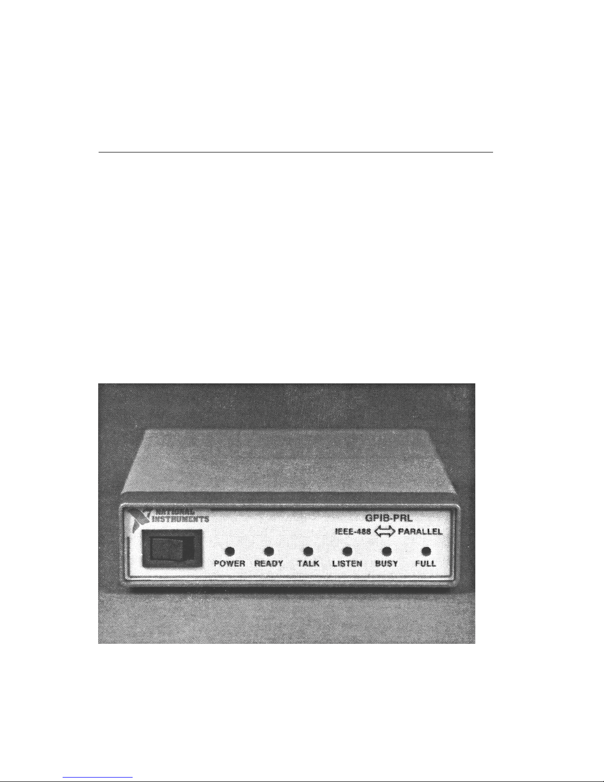
The GPIB-PRL, shown in Figure 1-1, provides a method of connecting a
device with a Centronics-type interface port to the IEEE 488 (GPIB) bus.
The GPIB-PRL allows transparent conversion of data between the two ports
so that control codes or special commands are not required. The GPIB-PRL
also increases the efficiency of the interface system by isolating the slower
device from the faster port with a 256 KB character buffer. This buffer is
used to offload the host computer during printer and plotter applications.
Figure 1-1. The GPIB-PRL
Page 12

Description of the GPIB-PRL Chapter 1
GPIB-PRL User Manual 1-2 © National Instruments Corp.
The GPIB-PRL is capable of providing data conversion in either direction;
that is, it can be used to interface GPIB plotters and printers to a computer
with a Centronics-type output port or to add a standard Centronics-type
printer to a GPIB network.
Although the GPIB-PRL is designed to be used with a device which adheres
to the Centronics interface standard, it can also be used with other devices
which use a unidirectional parallel 8-bit bus similar in nature to the
Centronics specification. Since the GPIB is also a parallel bus, to avoid
confusion the Centronics-type interface port is referred to as the parallel
port and the GPIB port is referred to as the GPIB or IEEE 488 throughout
the manual.
What Your Kit Contains
Your kit should contain the following components:
Component Part Number
One of the following boxes:
• GPIB-PRL (256K RAM - 115 VAC) 776177-02
• GPIB-PRL (256K RAM - 230 VAC) 776177-32
GPIB-PRL User Manual 320090-01
Page 13

Chapter 1 Description of the GPIB-PRL
© National Instruments Corp. 1-3 GPIB-PRL User Manual
Optional Equipment
Component Part Number
Rack Mount Kit:
Single (1 unit) 180480-01
Dual (2 units) 180480-02
Parallel (Centronics) Shielded Cables (2 meters):
Standard (36-pin male champ to 36-pin male champ) 180323-10
For IBM PC (25-pin D-sub to 36-pin male champ) 181073-20
Double Shielded GPIB Cables:
GPIB Type X2 Cable – 1 m 763061-01
GPIB Type X2 Cable – 2 m 763061-02
GPIB Type X2 Cable – 4 m 763061-03
GPIB-PRL Specifications
The following tables specify the electrical, environmental, and physical
characteristics of the GPIB-PRL.
Table 1-1. Electrical Characteristics
Characteristic Specification
Power Supply Unit Wall mount type, 115 VAC or 230 VAC,
50/60 Hz input, 9 VDC @ 1A max output
Voltage 9 VDC regulated
Current 640 mA typical; 1,500 mA max
Page 14

Description of the GPIB-PRL Chapter 1
GPIB-PRL User Manual 1-4 © National Instruments Corp.
Table 1-2. Environmental Characteristics
Characteristic Specification
Operating Temperature 10° to 40° C
Storage Temperature 0° to 70° C
Relative Humidity 10% to 95% noncondensing conditions
Noise Emissions FCC Class A Verified
Table 1-3. Physical Characteristics
Characteristic Specification
Case Size 1.6 in. by 5.7 in. by 8.4 in.(40.6 mm by
144.8 mm by 213.4 mm)
Case Material All metal enclosure
Rack Mounting Single or dual kits available
Weight 28 oz. (without power supply unit)
The GPIB-PRL Front Panel
The front panel of the GPIB-PRL is shown in the following figure. The
power switch and six light-emitting diodes (LEDs) are mounted on the
GPIB-PRL front panel.
GPIB-PRL
IEEE 488
PARALLEL
POWER READY TALK LISTEN BUSY FULL
Figure 1-2. The GPIB-PRL Front Panel
Page 15

Chapter 1 Description of the GPIB-PRL
© National Instruments Corp. 1-5 GPIB-PRL User Manual
The LEDs show the current status of the GPIB-PRL at all times. Table 1-4
describes each LED.
Table 1-4. LED Descriptions
LED Indication
POWER Indicates that power to the unit has been applied and the
ON/OFF switch is in the ON position.
READY Indicates that the power-on self-test has passed successfully
and the unit is ready to operate.
TALK Indicates that the GPIB-PRL is configured as a GPIB
Talker.
LISTEN Indicates that the GPIB-PRL is configured as a GPIB
Listener.
BUSY Indicates the current status of the parallel bus signal BUSY.
FULL Indicates that the internal data buffer of the GPIB-PRL has
become full. This is not an error condition, but is merely
a signal that bus performance may be reduced to the speed
of the slower interface.
Page 16

Description of the GPIB-PRL Chapter 1
GPIB-PRL User Manual 1-6 © National Instruments Corp.
The GPIB-PRL Rear Panel
The rear panel of the GPIB-PRL is shown in the following figure. The
power cable, parallel cable, and GPIB cable are shown connected to the rear
panel of the GPIB-PRL.
Figure 1-3. The GPIB-PRL Rear Panel
Page 17

Chapter 1 Description of the GPIB-PRL
© National Instruments Corp. 1-7 GPIB-PRL User Manual
The Parallel Connector
The parallel connector is a standard 36-pin shielded AMP Champ female
connector with bail-lock clips. The parallel connector will accept standard
36-pin Centronics-style male connectors. A diagram of the parallel
connector and the signals supported is shown below (a * suffix indicates
that the signal is active low).
N/C
N/C
GND
N/C
N/C
N/C
PE
BUSY
ACK*
DATA8
DATA7
DATA6
DATA5
DATA4
DATA3
DATA2
DMTA1
STROBE*
N/C
N/C
N/C
GND
ERROR*
INIT*
GND
GND
GND
GND
GND
GND
GND
GND
GND
GND
GND
GND
36
35
34
33
32
31
30
29
28
27
26
25
24
23
22
21
20
19
18
17
16
15
14
13
12
11
10
9
8
7
6
5
4
3
2
1
Figure 1-4. The Parallel Connector and Signal Designations
Page 18

Description of the GPIB-PRL Chapter 1
GPIB-PRL User Manual 1-8 © National Instruments Corp.
The GPIB Connector
The GPIB connector is a standard 24-pin shielded AMP Champ female
connector with metric screwlock hardware. A diagram of the GPIB
connector and the signals supported is shown below (a * suffix indicates
that the signal is active low).
DIO1*
DIO2*
DIO3*
DIO4*
EOI*
DAV*
NRFD*
NDAC*
IFC*
SRQ*
ATN*
SHIELD
DIO5*
DIO6*
DIO7*
DIO8*
REN*
GND (TW PAIR W/DAV*)
GND (TW PAIR W/NRFD*)
GND (TW PAIR W/NDAC*)
GND (TW PAIR W/IFC*)
GND (TW PAIR W/SRQ*)
GND (TW PAIR W/ATN*)
SIGNAL GROUND
1
2
3
4
5
6
7
8
9
10
11
12
13
14
15
16
17
18
19
20
21
22
23
24
Figure 1-5. The GPIB Connector and Signal Designations
Page 19

© National Instruments Corp 2-1 GPIB-PRL User Manual
Chapter 2
Installation and Operation
As mentioned in Chapter 1 the GPIB-PRL can transfer data either from the
GPIB port to the parallel port or from the parallel port to the GPIB port. The
parallel interface supports only unidirectional data transfers so the GPIB-PRL
must be configured to source data onto the parallel port or to receive data
from the parallel port.
If the parallel port is going to be the source of the data and a GPIB device will
be the end recipient of the data (as with a GPIB plotter connected via a
GPIB-PRL to the Centronics port on an IBM PC), you will be operating in
P (Parallel) mode.
Figure 2-1. Example of P Mode System Setup
If the GPIB port will be the source of the data and a parallel device will be
receiving the data (as with a Centronics printer interfaced to the IEEE 488 via
a GPIB-PRL), you will be operating in G (GPIB) mode.
Figure 2-2. Example of G Mode System Setup
Page 20

Installation and Operations Chapter 2
GPIB-PRL User Manual 2-2 © National Instruments Corp.
Installation
There are five basic steps to installing the GPIB-PRL.
1. Inspect the GPIB-PRL for damage that may have been caused in
shipment.
2. Verify the voltage requirement.
3. Configure the operating parameters.
4. Connect the cables.
5. Power on the unit.
These steps are described in more detail in the following sections.
Step 1. Inspection
Before you install the GPIB-PRL, inspect the shipping container and its
contents for damage. If damage appears to have been caused in shipment, file
a claim with the carrier. Retain the packing material for possible inspection
and/or for reshipment.
If the equipment appears to be damaged, do not attempt to operate it. Contact
National Instruments for instructions.
Step 2. Verify the Voltage Requirement
The GPIB-PRL is shipped from the factory with either a 115 V or 230 V wallmount supply. Verify that the voltage on the supply matches the voltage that
is supplied in your area.
Caution: Operating the unit at any voltage other than the one specified
could damage the unit.
Page 21

Chapter 2 Installation and Operation
© National Instruments Corp 2-3 GPIB-PRL User Manual
Step 3. Configure the Operating Parameters
The GPIB-PRL is shipped from the factory configured to operate in G mode
and set to the GPIB primary address of 5. If you wish to use the GPIB-PRL in
P mode or wish to change the GPIB primary address, it is necessary to open
the unit and set the configuration switches. To change the configuration
switches follow these steps:
1. Disconnect power to the unit and disconnect any cables that may be
connected to the unit.
2. Unscrew the two screws on the opposite sides of the rear panel.
3. Grab the rear panel bezel and pull it straight away from the rest of the
unit. The card should slide out the back of the enclosure.
4. Locate the configuration DIP switch (U22) on the printed wire board.
5. Set the switches for the desired mode of operation. Refer to Set
Configuration Switches later in this manual.
Caution: Most of the circuitry in the GPIB-PRL uses advanced
CMOS technology and can be damaged by static
electricity. Avoid touching any of the components and
take any necessary CMOS handling precautions.
6. Close the unit and reinsert the screws removed in Step 2.
Page 22

Installation and Operations Chapter 2
GPIB-PRL User Manual 2-4 © National Instruments Corp.
Set Configuration Switches
The DIP switch at location U22 on the printed wire board is used to configure
the GPIB-PRL. Figure 2-3 shows the factory default settings.
O
N
O
F
F
Key
= depressed side of switch handle
12345678
Figure 2-3. Factory Default Settings for Dip Switch U22
Default Settings
In Figure 2-3, switch 1 is in the OFF position; this indicates that the unit is
configured to operate in G Mode. Switches 2 and 3 are in the OFF position;
this indicates no service request will be generated when the buffer becomes
empty. Switches 4 through 8 are in the OFF OFF ON OFF ON positions,
respectively; this indicates a GPIB primary address of 5.
Tables 2-1, 2-2, and 2-3 show the possible configurations of the eight
switches and what the configurations indicate. Default settings are in shaded
rows.
Table 2-1. Configuration Switch Settings for Switch 1
Switch Position Indication
1 OFF Configures the GPIB-PRL to operate in G mode.
ON Configures the GPIB-PRL to operate in P mode.
Page 23

Chapter 2 Installation and Operation
© National Instruments Corp 2-5 GPIB-PRL User Manual
Table 2-2. Configuration Switch Settings for Switches 2 and 3
Switches Indication
2 3 G Mode P Mode
OFF OFF No SRQ on empty. The GPIB-PRL sends out listener
address on switches 4 through 8.
If switches 4 - 8 are all ON, all
possible listener addresses will be
sent.
OFF ON SRQ on empty. GPIB-PRL considers switches 4
through 8 to be its talk address.
ON OFF Not Used. No addressing is performed.
ON ON Not Used. Factory use only.
Table 2-3. Configuration Switch Settings for Switches 4 through 8
Switches Indication
45678
OFF OFF OFF OFF OFF GPIB Primary address 0
OFF OFF OFF OFF ON GPIB Primary address 1
OFF OFF OFF ON OFF GPIB Primary address 2
OFF OFF OFF ON ON GPIB Primary address 3
OFF OFF ON OFF OFF GPIB Primary address 4
OFF OFF ON OFF ON GPIB Primary address 5
OFF OFF ON ON OFF GPIB Primary address 6
OFF OFF ON ON ON GPIB Primary address 7
OFF ON OFF OFF OFF GPIB Primary address 8
OFF ON OFF OFF ON GPIB Primary address 9
OFF ON OFF ON OFF GPIB Primary address 10
(continues)
Page 24

Installation and Operations Chapter 2
GPIB-PRL User Manual 2-6 © National Instruments Corp.
Table 2-3. Configuration Switch Settings
for Switches 4 through 8 (continued)
Switches Indication
45678
OFF ON OFF ON ON GPIB Primary address 11
OFF ON ON OFF OFF GPIB Primary address 12
OFF ON ON OFF ON GPIB Primary address 13
OFF ON ON ON OFF GPIB Primary address 14
OFF ON ON ON ON GPIB Primary address 15
ON OFF OFF OFF OFF GPIB Primary address 16
ON OFF OFF OFF ON GPIB Primary address 17
ON OFF OFF ON OFF GPIB Primary address 18
ON OFF OFF ON ON GPIB Primary address 19
ON OFF ON OFF OFF GPIB Primary address 20
ON OFF ON OFF ON GPIB Primary address 21
ON OFF ON ON OFF GPIB Primary address 22
ON OFF ON ON ON GPIB Primary address 23
ON ON OFF OFF OFF GPIB Primary address 24
ON ON OFF OFF ON GPIB Primary address 25
ON ON OFF ON OFF GPIB Primary address 26
ON ON OFF ON ON GPIB Primary address 27
ON ON ON OFF OFF GPIB Primary address 28
ON ON ON OFF ON GPIB Primary address 29
ON ON ON ON OFF GPIB Primary address 30
ON ON ON ON ON Sets listen-only mode (G
mode) or sends out possible
Listener addresses (P mode)
Page 25

Chapter 2 Installation and Operation
© National Instruments Corp 2-7 GPIB-PRL User Manual
Step 4. Connect the Cables
The cables should be connected in the following order to ensure proper
connection:
1. Connect the parallel cable to the GPIB-PRL and close the bail-lock clips.
Connect the other end of the cable to your parallel device. Be sure to use
only shielded parallel cable.
2. Connect the GPIB cable to the GPIB-PRL and tighten the thumb screws
on the connector. Connect the other end to your GPIB system. Be sure
to obey all IEEE 488 cabling restrictions, and use shielded GPIB cable.
3. Connect the power jack of the wall-mount power supply to the power
receptacle on the back panel of the GPIB-PRL, then plug the supply into
an AC outlet of the correct voltage.
Note: To disconnect the cables, remove the GPIB cable before removing
the parallel cable so that the bail-lock clips can be unlocked.
Step 5. Power on the Unit
Power on your GPIB-PRL by using the front panel rocker switch. The
POWER LED should come on immediately and the READY indicator should
come on after the GPIB-PRL has passed its power-on self-test indicating the
unit is ready for operation.
If the READY indicator does not come on within seven seconds after the unit
is powered on, recheck all connections and switch settings and retry the
power-on sequence. If the READY light still fails to come on, contact
National Instruments.
Operation
The GPIB-PRL is now ready to operate. All characters sent to the unit will be
received at full speed and stored in the internal data buffer. The characters
will be sent to the receiving device at the rate of the receiving device.
If using the GPIB-PRL in P mode, turn on the GPIB instrument before turning
on the GPIB-PRL and be sure the configuration switches are set correctly.
Simply send data to your parallel port as you would if you had a parallel
device connected to it and the data will be converted and sent to the GPIB
instrument. If you are using a standard software package, such as a word
Page 26

Installation and Operations Chapter 2
GPIB-PRL User Manual 2-8 © National Instruments Corp.
processor with printing capabilities, the program will typically send the data
automatically to the parallel port when printing is selected.
If using the GPIB-PRL in G mode, simply address the GPIB-PRL to listen (if
not in listen-only mode) and send the desired data to the interface. The data
will be received and passed along automatically to the device connected to the
parallel port.
Page 27

© National Instruments Corp. 3-1 GPIB-PRL User Manual
Chapter 3
Technical Information
The GPIB-PRL is actually a powerful 8-bit microcomputer tailored for use
as an IEEE-488-to-parallel protocol converter. The unit's operating system
is contained in Read Only Memory (ROM) and can address up to 256 KB
of dynamic RAM. The GPIB-PRL microprocessor contains an integrated
Direct Memory Access (DMA) controller for high-speed data transfers from
the GPIB circuitry. The processor also contains an integrated memory
management unit, a dynamic RAM controller, a clock generator, a
programmable timer unit, and an interrupt controller.
The parallel port on the GPIB-PRL has been designed to source data onto
the parallel bus or to receive data from the parallel port (switch selectable).
All GPIB functionality is provided by an LSI GPIB controller chip which is
programmed and maintained by the operating system. Both the parallel port
and GPIB port are interrupt driven and feature extremely fast response
times to external data transfers. For more information on how the
individual modes of operation work, refer to the following sections.
G Mode Operation
When operating in G mode, the GPIB-PRL accepts data from the GPIB port
using the onboard DMA controller. The DMA controller transfers the data
directly to the memory buffer without processor intervention. This allows
for very high-speed GPIB transfer rates – as high as 900 kbytes/s. This
means that the GPIB system performance will not be degraded by
interfacing a "slow" printer or plotter to the interface.
The buffered data is then dumped to the device on the parallel interface at
its own rate. These two asynchronous events take place concurrently and
without user interaction. All operations are completely transparent to the
user.
If very large amounts of data are sent to the GPIB-PRL (greater than the
amount of RAM in the system) and the parallel device is a very slow data
acceptor, the GPIB-PRL internal data buffer might become full. In the
unlikely event that this does occur, the FULL indicator on the front panel
will illuminate and the GPIB transfer rate will slow to approximately the
same rate as the parallel device accepting the data. Since the maximum
data transfer rate on the GPIB is only as fast as the slowest listener, the
Page 28

Technical Information Chapter 3
GPIB-PRL User Manual 3-2 © National Instruments Corp.
GPIB system performance may become unacceptable if other GPIB devices
are required to transfer data on the bus.
To alleviate this problem, the GPIB-PRL has been designed with a special
SRQ-ON-EMPTY feature which can be enabled by setting the internal
configuration switches. If maximum GPIB performance is required at all
times this feature can be enabled and the GPIB-PRL will request service
from the GPIB Controller when its buffer is empty (indicating it is ready for
more data). The Controller can then determine the status of the GPIB-PRL
buffer by performing a serial poll and analyzing the response byte. If the
Controller observes that the GPIB-PRL buffer is empty, it can then send
data (up to the buffer size) to the GPIB-PRL and send the Unlisten
command to the GPIB-PRL so the GPIB can be used by other devices.
If the GPIB-PRL is serial polled, its response byte will depend on the status
of the internal data buffer. If the buffer is empty, a 41 hex will be returned
as the status byte. If the buffer is not empty, a 0 will be returned.
The GPIB-PRL will accept data at the GPIB address specified by the
configuration switches. The GPIB-PRL also has the ability to be
configured as a listen-only device if all GPIB address switches are set to
ON. In this mode, no addressing is required to make the GPIB-PRL a GPIB
listener and it cannot be unaddressed to listen. All data transferred on the
GPIB will be accepted by the GPIB-PRL and output to the parallel port
(even if the data was intended for another device). This scheme could be
used to monitor all GPIB data bus activity.
Note: When the GPIB-PRL is configured as a listen-only device, it may
not be serial polled.
If the GPIB-PRL receives the universal Device CLear (DCL) command or
its listen address and the Selected Device Clear (SDC) command, the
GPIB-PRL will clear its internal data buffer and reset to its power-up state.
The GPIB-PRL will also pulse the parallel port signal INIT* so that the
parallel device will be initialized.
In G mode, the GPIB-PRL may act only as a GPIB Listener. The
GPIB-PRL should not be passed control. If it is, the GPIB circuitry in the
GPIB-PRL will accept control and immediately assert ATN*. This is an
error condition which may lock up your system and, therefore, should be
avoided. Neither Trigger nor Go To Local has any effect on the GPIBPRL.
Page 29

Chapter 3 Technical Information
© National Instruments Corp. 3-3 GPIB-PRL User Manual
The interface signal descriptions and timing relationships for the G mode
parallel port signals are shown in the following table.
G Mode Parallel Interface
Signal Return Signal Direction Description
Pin Pin
119STROBE* OUT The STROBE* pulse is used to
signal that data on the bus is valid.
Pulse width will be greater than 0.5
µsec.
220DATA1 OUT These signals represent the data
321DATA2 OUT byte being transferred. Each
421DATA3 OUT signal is at a HIGH level when
523DATA4 OUT data is a logical 1 and a LOW
624DATA5 OUT level when data is a logical 0.
725DATA6 OUT DATA1 is the lowest order
826DATA7 OUT bit and DATA8 is the highest
927DATA8 OUT order bit. The data will be stable on
the bus at least 0.5 µsec before
STROBE* is asserted and will
remain on the bus at least 0.5 µsec
after STROBE*is unasserted.
10 28 ACKNLG* IN Indicates that the data has been
received by the parallel device.
This signal should be active at least
0.5 µsec.
19-30 - GND - Twisted-pair ground return lines for
signals on pins 1-10.
31 - INIT* OUT Asserted when the GPIB-PRL
receives either a universal device
clear (DCL) or its listen address and
a selected device clear (SDC). This
signal will be asserted for
approximately 100 µsec.
33 - GND - Same as for pins 19-30.
Page 30

Technical Information Chapter 3
GPIB-PRL User Manual 3-4 © National Instruments Corp.
0.5 µsec (min)
0.5 µsec (min)
0.5 µsec (min)
0.5 µsec (min)
STROBE*
DATA
ACKNLG*
Figure 3-1. G Mode Parallel Interface Timing
P Mode Operation
P mode operation is similar to G mode operation except that the data is
input from the parallel port and output to the GPIB port. The incoming data
is stored in the internal data buffer until it is accepted by the GPIB device.
The GPIB functionality implemented in P Mode is the ability to address a
GPIB device to listen, the ability to talk and send data, and the ability to
assert IFC* and to send the device clear command.
Upon power-on, the GPIB-PRL will read the status of the configuration
switches and initialize the system. If switch 3 is OFF, the GPIB-PRL will
be the System Controller and will assert IFC* for 500 µsec. The action of
asserting IFC* for at least 100 µsec initializes the GPIB and makes the
System Controller Controller-In-Charge (CIC). If switch 2 is also OFF, the
GPIB-PRL will then send the GPIB listen address on switches 4-8.
Switches 4-8 set the GPIB address configuration. If switches 4-8 are on, all
30 possible listen addresses are sent. This is useful if you do not know or
do not care what your GPIB device's primary address is. By sending all
possible listen addresses, the GPIB-PRL is sure to send out the one your
instrument is expecting. This could also be used in a scheme where you
have more than one printer or plotter of the same type producing multiple
copies of a document or drawing. The GPIB-PRL will always assert REN*
when addressing other devices.
Page 31

Chapter 3 Technical Information
© National Instruments Corp. 3-5 GPIB-PRL User Manual
If switch 2 is ON and switch 3 is OFF, the GPIB-PRL will not send out a
listen address but will be the System Controller and will assert IFC*. This
mode can be used if the GPIB-PRL is connected to a listen-only device
which does not require addressing. In the above mentioned modes the
GPIB-PRL will be programmed as a talk-only device.
If switch 2 is OFF and switch 3 is ON, the GPIB address on the switch will
be considered the GPIB-PRL talk address. In this mode the GPIB-PRL will
not be the System Controller and it does not have the ability to address itself
or any other GPIB device. There must be a GPIB controller on the bus
which will address the GPIB-PRL to talk and another GPIB device to listen.
If the parallel port signal INIT* is asserted, it will cause the GPIB-PRL to
clear its internal buffer. Also, either the SDC or DCL command (mode
dependent) will be sent over the GPIB to initialize the GPIB device.
The interface signal descriptions and timing relationships for the parallel
port while in P Mode are shown in the following table.
Page 32

Technical Information Chapter 3
GPIB-PRL User Manual 3-6 © National Instruments Corp.
P Mode Parallel Interface
Signal Return Signal Direction Description
Pin Pin
119STROBE* IN The STROBE* pulse tells the
GPIB-PRL that the data on the bus is
valid. The GPIB-PRL will read the
data in on the rising edge of
STROBE*. The STROBE* signal
should be asserted for at least 0.5
µsec.
220DATA1 IN These signals represent the data
321DATA2 IN byte being transferred. Each
422DATA3 IN signal is at a HIGH level when
523DATA4 IN data is a logical 1 and a LOW
624DATA5 IN level when data is a logical 0.
725DATA6 IN DATA1 is the lowest order bit
826DATA7 IN and DATA8 is the highest order
927DATA8 IN bit. This data should be stable on the
bus at least 0.5 µsec before
STROBE* is asserted and should
remain on the bus at least 0.5 µsec
after STROBE* is unasserted.
10 28 ACKNLG* OUT Indicates that the data has been
received by the GPIB-PRL and it is
ready to accept more data.
ACKNLG* will be asserted for a
minimum of 10 µsec.
11 29 BUSY OUT A HIGH signal indicates that the
GPIB-PRL is busy and cannot
accept more data. BUSY will be
high when a byte has been sent to the
GPIB-PRL but has not yet been
accepted.
19-30 - GND - Twisted-pair ground return lines for
signals on pins 1-11.
Page 33

Chapter 3 Technical Information
© National Instruments Corp. 3-7 GPIB-PRL User Manual
Signal Return Signal Direction Description
Pin Pin
31 - INIT* IN When this signal is asserted, the
GPIB-PRL will be reset to its powerup state and its internal buffer is
cleared. The DCL or SDL command
will be sent to the GPIB device.
INIT* should be asserted for a
minimum of 50 µsec.
33 - GND - Same as for pins 19-30.
0.5 µsec (min)
0.5 µsec (min)
0.5 µsec (min)
0.5 µsec (min)
DATA
STROBE*
ACKNLG*
BUSY
Figure 3-2. P Mode Parallel Interface Timing
Page 34

Appendix A
Customer Communication
For your convenience, this appendix contains forms to help you gather the
information necessary to help us solve technical problems you might have
as well as a form you can use to comment on the product documentation.
Filling out a copy of the Technical Support Form before contacting National
Instruments helps us help you better and faster.
National Instruments provides comprehensive technical assistance around
the world. In the U.S. and Canada, applications engineers are available
Monday through Friday from 8:00 a.m. to 6:00 p.m. (central time). In other
countries, contact the nearest branch office. You may fax questions to us at
any time.
Corporate Headquarters
(800) 433-3488 (toll-free U.S. and Canada)
Technical Support fax: (512) 794-5678
Branch Offices Phone Number Fax Number
Australia 03 879 9422 03 879 9179
Austria 0662 435986 0662 437010 19
Belgium 02 757 00 20 02 757 03 11
Denmark 45 76 26 00 45 76 71 11
Finland 90 527 2321 90 502 2930
France 1 48 65 33 00 1 48 65 19 07
Germany 089 7 14 50 93 089 7 14 60 35
Italy 02 48301892 02 48301915
Japan 03 3788 1921 03 3788 1923
Netherlands 01720 45761 01720 42140
Norway 03 846866 03 846860
Spain 91 640 0085 91 640 0533
Sweden 08 730 49 70 08 730 43 70
Switzerland 056 27 00 20 056 27 00 25
U.K. 0635 523545 0635 523154
or 0800 289877 (in U.K. only)
Page 35

Technical Support Form
Technical support is available at any time by fax. Include the information
from your configuration form. Use additional pages if necessary.
Name
Company
Address
Fax ( ) Phone ( )
Computer brand
Model Processor
Operating system
Speed MHz RAM MB
Display adapter
Mouse yes no
Other adapters installed
Hard disk capacity MB Brand
Instruments used
National Instruments hardware product model
Revision
Configuration
National Instruments software product
Version
Configuration
(continues)
Page 36

The problem is
List any error messages
The following steps will reproduce the problem
Page 37

Hardware Configuration Form
Record the settings and revisions of your hardware on the line to the right of
each item. Update this form each time you revise your hardware
configuration, and use this form as a reference for your current
configuration.
National Instruments Products
• GPIB-PRL Revision
• Switch Settings:
Other Products
• Computer Make and Model
• Microprocessor
• Clock Frequency
• Type of Monitor Card Installed
• Application Programming Language (BASIC, C, Pascal, and so on)
Page 38

Documentation Comment Form
National Instruments encourages you to comment on the documentation
supplied with our products. This information helps us provide quality
products to meet your needs.
Title: GPIB-PRL User Manual
Edition Date: November 1993
Part Number: 320090-01
Please comment on the completeness, clarity, and organization of the
manual.
(continues)
Page 39

If you find errors in the manual, please record the page numbers and
describe the errors.
Thank you for your help.
Name
Title
Company
Address
Phone ( )
Mail to: Technical Publications
National Instruments Corporation
6504 Bridge Point Parkway, MS 53-02
Austin, TX 78730-5039
Fax to: Technical Publications
National Instruments Corporation
MS 53-02
(512) 794-5678
Page 40

Glossary
Prefix Meaning Value
mkM-
millikilomega-
10
-3
10
3
10
6
° degrees
% percent
A amperes
AC alternating current
ANSI American National Standards Institute
C Celsius
CMOS complementary metal-oxide semiconductor
EMI electromagnetic interference
FCC Federal Communications Commission
GPIB General Purpose Interface Bus
Hz hertz
IEEE Institute of Electrical and Electronic Engineers
in. inches
KB kilobytes of memory
LED light-emitting diode
m meters
MB megabytes of memory
s seconds
VAC volts alternating current
VDC volts direct current
 Loading...