

Page 1

Getting Started with Your
GPIB-PCII/IIA and
the NI-488.2
™
Software
for MS-DOS/Windows Graphics
Applications
October 1994 Edition
Part Number 320269B-01
© Copyright 1990, 1994 National Instruments Corporation.
All Rights Reserved.
Page 2

National Instruments Corporate Headquarters
6504 Bridge Point Parkway
Austin, TX 78730-5039
(512) 794-0100
Technical support fax: (800) 328-2203
(512) 794-5678
Branch Offices:
Australia (03) 879 9422, Austria (0662) 435986, Belgium 02/757.00.20,
Canada (Ontario) (519) 622-9310, Canada (Québec) (514) 694-8521,
Denmark 45 76 26 00, Finland (90) 527 2321, France (1) 48 14 24 24,
Germany 089/741 31 30, Italy 02/48301892, Japan (03) 3788-1921,
Mexico 95 800 010 0793, Netherlands 03480-33466, Norway 32-84 84 00,
Singapore 2265886, Spain (91) 640 0085, Sweden 08-730 49 70,
Switzerland 056/20 51 51, Taiwan 02 377 1200, U.K. 0635 523545
Page 3

Limited Warranty
The GPIB-PCII/IIA is warranted against defects in materials and
workmanship for a period of two years from the date of shipment, as
evidenced by receipts or other documentation. National Instruments will, at
its option, repair or replace equipment that proves to be defective during the
warranty period. This warranty includes parts and labor.
The media on which you receive National Instruments software are
warranted not to fail to execute programming instructions, due to defects in
materials and workmanship, for a period of 90 days from date of shipment,
as evidenced by receipts or other documentation. National Instruments will,
at its option, repair or replace software media that do not execute
programming instructions if National Instruments receives notice of such
defects during the warranty period. National Instruments does not warrant
that the operation of the software shall be uninterrupted or error free.
A Return Material Authorization (RMA) number must be obtained from the
factory and clearly marked on the outside of the package before any
equipment will be accepted for warranty work. National Instruments will
pay the shipping costs of returning to the owner parts which are covered by
warranty.
National Instruments believes that the information in this manual is
accurate. The document has been carefully reviewed for technical accuracy.
In the event that technical or typographical errors exist, National
Instruments reserves the right to make changes to subsequent editions of
this document without prior notice to holders of this edition. The reader
should consult National Instruments if errors are suspected. In no event
shall National Instruments be liable for any damages arising out of or
related to this document or the information contained in it.
EXCEPT AS SPECIFIED HEREIN, NATIONAL INSTRUMENTS MAKES NO
WARRANTIES
ANY WARRANTY OF MERCHANTABILITY OR FITNESS FOR A
PARTICULAR PURPOSE
CAUSED BY FAULT OR NEGLIGENCE ON THE PART OF
, EXPRESS OR IMPLIED, AND SPECIFICALLY DISCLAIMS
. CUSTOMER'S RIGHT TO RECOVER DAMAGES
NATIONAL
INSTRUMENTS SHALL BE LIMITED TO THE AMOUNT THERETOFORE
PAID BY THE CUSTOMER
LIABLE FOR DAMAGES RESULTING FROM LOSS OF DATA
USE OF PRODUCTS, OR INCIDENTAL OR CONSEQUENTIAL DAMAGES,
EVEN IF ADVISED OF THE POSSIBILITY THEREOF. This limitation of the
. NATIONAL INSTRUMENTS WILL NOT BE
, PROFITS,
liability of National Instruments will apply regardless of the form of action,
Page 4

whether in contract or tort, including negligence. Any action against
National Instrument must be brought within one year after the cause of
action accrues. National Instruments shall not be liable for any delay in
performance due to causes beyond its reasonable control. The warranty
provided herein does not cover damages, defects, malfunctions, or service
failures caused by owner's failure to follow the National Instruments
installation, operation, or maintenance instructions; owner's modification of
the product; owner's abuse, misuse, or negligent acts; and power failure or
surges, fire, flood, accident, actions of third parties, or other events outside
reasonable control.
Copyright
Under the copyright laws, this book may not be copied, photocopied,
reproduced, or translated, in whole or in part, without the prior written
consent of National Instruments Corporation.
Trademarks
NAT4882® and NI-488.2™ are trademarks of National Instruments
Corporation.
Product and company names listed are trademarks or trade names of their
respective companies.
WARNING REGARDING MEDICAL AND
CLINICAL USE OF NATIONAL
INSTRUMENTS PRODUCTS
National Instruments products are not designed with components and testing
intended to ensure a level of reliability suitable for use in treatment and
diagnosis of humans. Applications of National Instruments products
involving medical or clinical treatment can create a potential for accidental
injury caused by product failure, or by errors on the part of the user or
application designer. Any use or application of National Instruments
products for or involving medical or clinical treatment must be performed by
properly trained and qualified medical personnel, and all traditional medical
safeguards, equipment, and procedures that are appropriate in the particular
situation to prevent serious injury or death should always continue to be
used when National Instruments products are being used. National
Instruments products are NOT intended to be a substitute for any form of
established process, procedure, or equipment used to monitor or safeguard
human health and safety in medical or clinical treatment.
Page 5

FCC/DOC Radio Frequency
Interference Compliance
This equipment generates and uses radio frequency energy and, if not
installed and used in strict accordance with the instructions in this manual,
may cause interference to radio and television reception. This equipment
has been tested and found to comply with the following two regulatory
agencies:
Federal Communications Commission
This device complies with Part 15 of the Federal Communications
Commission (FCC) Rules for a Class B digital device. A Class B device is
distinguishable from a Class A device by the appearance of an FCC ID
number located on the Class B device.
Canadian Department of Communications
This device complies with the limits for radio noise emissions from digital
apparatus set out in the Radio Interference Regulations of the Canadian
Department of Communications (DOC).
Le présent appareil numérique n’émet pas de bruits radioélectriques
dépassant les limites applicables aux appareils numériques de classe B
prescrites dans le règlement sur le brouillage radioélectrique édicté par le
ministère des communications du Canada.
Instructions to Users
These regulations are designed to provide reasonable protection against
interference from the equipment to radio and television reception in
residential areas.
There is no guarantee that interference will not occur in a particular
installation. However, the chances of interference are much less if the
equipment is installed and used according to this instruction manual.
Page 6

If the equipment does cause interference to radio or television reception,
which can be determined by turning the equipment on and off, one or more
of the following suggestions may reduce or eliminate the problem.
• Operate the equipment and the receiver on different branches of your
AC electrical system.
• Move the equipment away from the receiver with which it is interfering.
• Reorient or relocate the receiver’s antenna.
• Be sure that the equipment is plugged into a grounded outlet and that
the grounding has not been defeated with a cheater plug.
Notice to user: Changes or modifications not expressly approved by
National Instruments could void the user’s authority to
operate the equipment under the FCC Rules.
If necessary, consult National Instruments or an experienced radio/television
technician for additional suggestions. The following booklet prepared by
the FCC may also be helpful: How to Identify and Resolve Radio-TV
Interference Problems. This booklet is available from the U.S. Government
Printing Office, Washington, DC 20402, Stock Number 004-000-00345-4.
Page 7

Contents
About This Manual ..........................................................................xiii
Organization of This Manual......................................................xiii
Conventions Used in This Manual.............................................xiv
Related Documentation ..............................................................xv
Customer Communication..........................................................xv
Chapter 1
Introduction and Hardware Installation
What You Need to Get Started...................................................1-1
Optional Equipment....................................................................1-2
Hardware Description.................................................................1-2
Software Description..................................................................1-3
Installing the GPIB-PCII/IIA ..................................................... 1-3
Chapter 2
NI-488.2 Software Files
NI-488.2 Software Programs and Files for MS-DOS................. 2-1
NI-488.2 Software Programs and Files for Windows ...............2-2
................................................................... 2-1
Chapter 3
Software Installation
Installing the NI-488.2 Software for MS-DOS...........................3-1
Step 1. Run INSTALL...............................................3-1
Step 2. Test the Software Installation ........................3-2
Installing the NI-488.2 Software for Windows ..........................3-3
Step 1. Run INSTALL...............................................3-3
Step 2. Set Up the Windows Applications.................3-4
Step 3. Test the Software Installation ........................3-5
....................................................................... 3-1
................................. 1-1
Appendix A
Hardware Specifications
................................................................A-1
Appendix B
Changing Board and Device Characteristics
Board and Device Characteristics............................................... B-1
Characteristics of the Graphics Devices.......................B-1
Characteristics of Each GPIB-PCII/IIA ......................B-2
© National Instruments Corp. ix GPIB-PCII/IIA for Graphics
......................... B-1
Page 8

Contents
Default Configurations............................................................... B-2
Primary Default Characteristics................................... B-3
Repeat Addressing (Device Characteristic Only) ........B-4
Changing Board and Device Characteristics..............................B-4
Changing Characteristics for MS-DOS........................B-4
Running IBCONF..........................................B-4
Changing Characteristics for Windows ....................... B-5
Running WIBCONF ......................................B-5
Appendix C
Hardware and Software Configuration
Verifying the GPIC-PC Mode Setting........................................C-2
Verifying the Hardware Configuration Settings......................... C-3
Changing Hardware Configuration Settings............................... C-4
Step 1. Configure the Hardware................................. C-4
Base I/O Address Selection...........................C-4
GPIC-PCII Mode.............................C-5
GPIC-PCIIA Mode..........................C-7
Possible Conflicts............................C-9
Interrupt Selection ......................................... C-11
Shared Interrupts in GPIC-PCIIA
Mode................................................C-12
Possible Conflicts............................C-16
DMA Channel Selection................................C-17
Possible Conflicts............................C-19
Shield Ground Configuration.........................C-19
Step 2. Run the IBDIAG Diagnostic Program...........C-20
Step 3. Configure the Software..................................C-20
Configuring the Software for MS-DOS.........C-21
Configuring the Software for Windows.........C-22
................................... C-1
Appendix D
Interactive Software Installation
INSTALL for MS-DOS..............................................................D-1
Installing the Software for MS-DOS ...........................D-2
Running IBDIAG for MS-DOS................................... D-3
Exiting INSTALL ........................................................D-3
INSTALL for Windows ............................................................. D-4
Installing the Software for Windows ...........................D-4
Running IBDIAG for Windows...................................D-5
Exiting INSTALL ........................................................D-5
GPIB-PCII/IIA for Graphics x © National Instruments Corp.
................................................D-1
Page 9

Contents
Appendix E
Customer Communication
............................................................E-1
Glossary.................................................................................................G-1
Figures
Figure 1-1. Installing the GPIB-PCII/IIA...........................................1-4
Figure C-1. GPIC-PCII/IIA Parts Locator Diagram...........................C-1
Figure C-2. GPIC-PC Mode Selection Settings..................................C-2
Figure C-3. Base I/O Address Switch Settings for GPIC-PCII
Mode................................................................................C-6
Figure C-4. Base I/O Address Switch Settings for GPIC-PCIIA
Mode................................................................................C-7
Figure C-5. Default Interrupt Jumper Setting for GPIC-PCII Mode ..C-12
Figure C-6. Default Interrupt Jumper Setting for GPIC-PCIIA
Mode................................................................................C-13
Figure C-7. Interrupt Jumper Settings for GPIC-PCIIA Mode...........C-14
Figure C-8. DMA Channel Jumper Setting for DMA Channel 1.......C-18
Figure C-9. Ground Configuration Jumper Settings...........................C-20
Tables
Table A-1. Electrical Characteristics.................................................A-1
Table A-2. Environmental Characteristics.........................................A-1
Table A-3. Physical Characteristics................................................... A-2
Table C-1. Factory Default Settings and Available Configurations
for GPIC-PCII Mode .......................................................C-3
Table C-2. Factory Default Settings and Available Configurations
for GPIC-PCIIA Mode.....................................................C-3
Table C-3. I/O Addresses Used by Other Devices.............................C-10
Table C-4. Interrupt Levels Used by Other Devices .........................C-16
Table C-5. DMA Channels for the GPIC-PCII/IIA...........................C-18
© National Instruments Corp. xi GPIB-PCII/IIA for Graphics
Page 10

About This Manual
This manual contains instructions for installing and configuring the
National Instruments GPIB-PCII/IIA interface board and the NI-488.2
software handler for MS-DOS/Windows graphics applications.
Organization of This Manual
This manual is organized as follows:
• Chapter 1, Introduction and Hardware Installation, lists what you need
to get started and optional equipment you can order, gives a brief
description of the hardware and the NI-488.2 software, and contains
instructions for installing your GPIB-PCII/IIA.
• Chapter 2, NI-488.2 Software Files, describes the software files
contained on your NI-488.2 distribution diskette.
• Chapter 3, Software Installation, contains instructions for installing the
NI-488.2 software files.
• Appendix A, Hardware Specifications, describes the electrical,
environmental, and physical characteristics of the GPIB-PCII/IIA and
the recommended operating conditions.
• Appendix B, Changing Board and Device Characteristics, contains
instructions for changing the default board and device characteristics of
the NI-488.2 handler for MS-DOS/Windows.
• Appendix C, Hardware and Software Configuration, contains
instructions for changing the configuration settings of your
GPIB-PCII/IIA.
• Appendix D, Interactive Software Installation, contains instructions for
running the interactive version of INSTALL.
• Appendix E, Customer Communication, contains forms you can use to
request help from National Instruments or to comment on our products
and manuals.
© National Instruments Corp. xiii GPIB-PCII/IIA for Graphics
Page 11

About This Manual
• The Glossary contains an alphabetical list and description of terms used
in this manual, including abbreviations, acronyms, metric prefixes,
mnemonics, and symbols.
Conventions Used in This Manual
Throughout this manual, the following conventions are used to distinguish
elements of text:
bold Bold text denotes menus, menu items, dialog
buttons, or options.
italic Italic text denotes emphasis, a cross reference, or
an introduction to a key concept.
bold italic Bold italic text denotes a note, caution, or
warning.
monospace Text in this font denotes text or characters that
are to be literally input from the keyboard,
sections of code, programming examples, and
syntax examples. This font is also used for the
proper names of disk drives, paths, directories,
programs, subprograms, subroutines, device
names, functions, variables, filenames, and
extensions, and for statements and comments
taken from program code.
italic monospace
<> Angle brackets enclose the name of a key on the
- A hyphen between two or more key names
<Shift> Key names are capitalized.
GPIB-PCII/IIA for Graphics xiv © National Instruments Corp.
Italic text in this font denotes that you must
supply the appropriate words or values in the
place of these items.
keyboard—for example, <Ctrl>.
enclosed in angle brackets denotes that you
should simultaneously press the named keys—
for example, <Ctrl-Alt-Del>.
Page 12

About This Manual
Enter Enter is reserved to mean that the commands
immediately succeeding the word must be typed
into the computer, and then executed by pressing
the <Enter> key on the keyboard.
IEEE 488 and IEEE 488 and IEEE 488.2 refer to the
IEEE 488.2 ANSI/IEEE Standard 488.1-1987 and the
ANSI/IEEE Standard 488.2-1987, respectively,
which define the GPIB.
Abbreviations, acronyms, metric prefixes, mnemonics, symbols, and terms
are listed in the Glossary.
Related Documentation
The following documents contain information that you may find helpful as
you read this manual.
• ANSI/IEEE Standard 488.1-1987, IEEE Standard Digital Interface for
Programmable Instrumentation
• ANSI/IEEE Standard 488.2-1987, IEEE Standard Codes, Formats,
Protocols, and Common Commands
• Microsoft MS-DOS User's Guide, Microsoft Corporation
• Microsoft Windows User's Guide, Microsoft Corporation
Customer Communication
National Instruments wants to receive your comments on our products and
manuals. We are interested in the applications you develop with our
products, and we want to help if you have problems with them. To make it
easy for you to contact us, this manual contains comment and configuration
forms for you to complete. These forms are in Appendix E, Customer
Communication, at the end of this manual.
© National Instruments Corp. xv GPIB-PCII/IIA for Graphics
Page 13

Chapter 1 Introduction and Hardware Installation
This chapter lists what you need to get started and optional equipment you
can order, gives a brief description of the hardware and the NI-488.2
software, and contains instructions for installing your GPIB-PCII/IIA.
What You Need to Get Started
GPIB-PCII/IIA interface board set for one of the following modes:
GPIB-PCIIA
or
GPIB-PCII
3.5 in. NI-488.2 Distribution Diskette for Graphics Applications
MS-DOS/Windows
One of the following operating systems installed on your computer:
MS-DOS version 3.0 or higher (or equivalent)
or
Windows version 3.1 or higher
© National Instruments Corp. 1-1 GPIB-PCII/IIA for Graphics
Page 14

Introduction and Hardware Installation Chapter 1
Optional Equipment
You can contact National Instruments to order any of the following optional
equipment.
• GPIB Bus Extenders
Parallel – 100 to 120 VAC
Parallel – 220 to 240 VAC
Fiber-optic – 100 to 120 VAC
Fiber-optic – 220 to 240 VAC
Coaxial – 100 to 120 VAC
Coaxial – 220 to 240 VAC
• GPIB Connector Extender
• GPIB-SWITCH Box
• Shielded GPIB Cables*
Type X1 single-shielded cables (1 m, 2 m, or 4 m)
Type X2 double-shielded cables (1 m, 2 m, or 4 m)
* To meet FCC emission limits for this Class B device, you must use a
shielded (Type X1 or X2) GPIB cable. Operating this equipment with
a non-shielded cable may cause interference to radio and television
reception in residential areas.
Hardware Description
The GPIB-PCII/IIA interface board combines the functionality of the
National Instruments GPIB-PCII and GPIB-PCIIA interface boards. It can
be configured to function as either a GPIB-PCII or a GPIB-PCIIA,
depending on the setting of the configuration switches on the board. To
verify the GPIB-PC mode setting of your board, refer to Verifying the
GPIB-PC Mode Setting in Appendix C, Hardware and Software
Configuration, later in this manual.
The GPIB-PCII/IIA, equipped with the NAT4882 ASIC, transforms any
IBM PC, PC/XT, PC AT, or compatible computer into a full-functioning
IEEE 488.2 Talker/Listener/Controller. The NAT4882 controller chip is
fully compatible with the IEEE 488.2 standard.
GPIB-PCII/IIA for Graphics 1-2 © National Instruments Corp.
Page 15

Chapter 1 Introduction and Hardware Installation
You can use standard GPIB cables to connect the GPIB-PCII/IIA with up to
14 instruments. If you want to use more instruments, you can order a bus
extender or expander from National Instruments. Refer to Appendix A,
Hardware Specifications, for more information about the GPIB-PCII/IIA
hardware specifications and recommended operating conditions.
Software Description
Your kit includes NI-488.2 software, which National Instruments has
developed for use with the GPIB-PCII/IIA. The NI-488.2 software and
the GPIB hardware transform a general-purpose PC into a GPIB
Talker/Listener/Controller that has complete communications and bus
management capability. Your kit includes the NI-488.2 software for
MS-DOS and for Windows.
Installing the GPIB-PCII/IIA
Warning: Several components on your GPIB-PCII/IIA board can be
damaged by electrostatic discharge. To avoid such damage
in handling the board, touch the antistatic plastic package to
a metal part of your computer chassis before removing the
board from the package.
Perform the following steps to install the GPIB-PCII/IIA:
1. Turn off your computer and all external devices, such as monitors or
tape drives.
2. Unplug the power cord from the wall outlet.
3. Remove the top cover or access port of the I/O channel.
4. Remove the expansion slot cover on the back panel of the computer.
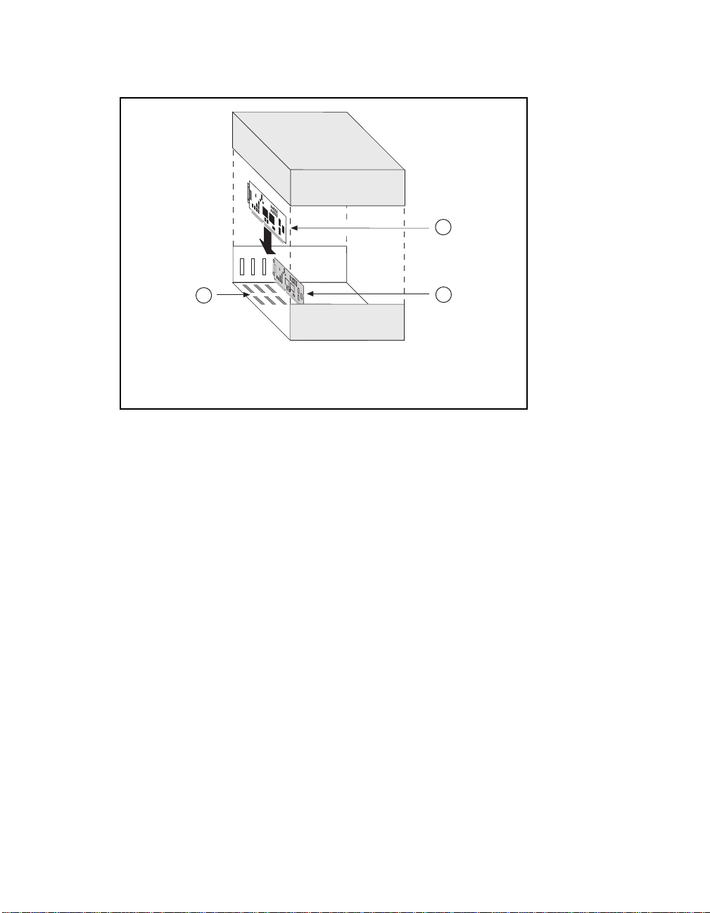
5. Insert the GPIB-PCII/IIA into any unused slot with the GPIB
connector sticking out of the opening on the back panel, as shown in
Figure 1-1. It might be a tight fit, but do not force the board into place.
© National Instruments Corp. 1-3 GPIB-PCII/IIA for Graphics
Page 16
Introduction and Hardware Installation Chapter 1
1
2
1 GPIB-PCII/IIA board
2 Back panel
3 PC AT plug-in board
3
Figure 1-1. Installing the GPIB-PCII/IIA
6. Screw the mounting bracket of the GPIB-PCII/IIA to the back panel rail of
the computer.
7. Verify that the GPIB-PCII/IIA is securely installed.
8. Replace the retaining screw of the expansion slot cover if there is one.
9. Replace the cover on the computer.
10. Plug the power cord into the wall outlet.
11. Turn on your computer and external devices.
The GPIB-PCII/IIA interface board is now installed.
Note: Do not attach the GPIB cable to the extension receptacle on the
board until after you run the hardware and software diagnostic
programs, IBDIAG and IBTEST, which are explained in
Chapter 3, Software Installation. These programs may not
function properly if the GPIB cable is attached.
GPIB-PCII/IIA for Graphics 1-4 © National Instruments Corp.
Page 17

Chapter 2 NI-488.2 Software Files
This chapter describes the software files contained on your NI-488.2
distribution diskette.
If you are using the NI-488.2 software for Windows, skip to NI-488.2
Software Programs and Files for Windows, later in this chapter. If you are
using the NI-488.2 software for MS-DOS, proceed with the next section,
NI-488.2 Software Programs and Files for MS-DOS.
NI-488.2 Software Programs and Files for MS-DOS
The NI-488.2 software for MS-DOS contains the following programs and
files.
• GPIB.COM is the NI-488.2 software handler file that is loaded at
system startup by DOS. Handler is a term used by National
Instruments to refer to a loadable device driver.
• IBDIAG.EXE is a program that tests the hardware installation. After
the handler is installed, IBTEST.BAT confirms that both the software
and hardware are installed and functioning properly.
• INSTALL.EXE is a multipurpose, menu-driven program that installs
the NI-488.2 software and tests the hardware and software
configuration. When INSTALL.EXE installs the NI-488.2 software, it
updates CONFIG.SYS, the MS-DOS system configuration file.
• IBTEST.EXE is a program that tests the installation of the NI-488.2
software.
• IBCONF.EXE is a software configuration program that changes the
configuration parameters of the NI-488.2 software handler.
© National Instruments Corp. 2-1 GPIB-PCII/IIA for Graphics
Page 18

NI-488.2 Software Files Chapter 2
• IBIC.EXE is an interactive control program that executes GPIB
functions you enter from the keyboard. It helps you establish
communication between your computer and your graphics device.
• README.DOC is a Readme file that discusses the NI-488.2 handler.
After you have reviewed all the programs and files on your distribution
diskette, skip to Chapter 3, Software Installation.
NI-488.2 Software Programs and Files for Windows
The NI-488.2 software for Windows contains the following programs and
files.
• GPIB.DLL is a dynamic link library that is accessed by a Windows
GPIB application as it executes. It contains all of the GPIB functions.
• GPIB.INI is the private profile file that GPIB.DLL uses to determine
the software configuration parameters for each GPIB board and device
in the system. You can modify it by using either the WIBCONF.EXE
program or a text editor.
• WIBCONF.EXE, an MS-DOS application, is a software configuration
program that you can use to change the software parameters and other
data used by the handler. It operates in much the same way as the
GPIB MS-DOS configuration program, IBCONF.
• WIBCONF.PIF contains configuration information about the program
WIBCONF.EXE that is used by Windows when it is executed.
• IBDIAG.EXE, a DOS application, is a program that tests the hardware
settings on your GPIB board. It ensures that the board is properly
installed and that the hardware is accessible.
• IBDIAG.PIF contains configuration information about the program
IBDIAG.EXE that is used by Windows when it is executed.
GPIB-PCII/IIA for Graphics 2-2 © National Instruments Corp.
Page 19

Chapter 2 NI-488.2 Software Files
• WIBTEST.EXE, a Windows application, can be used to test the
software handler. It verifies that the software configuration is
consistent with the GPIB hardware.
• WIBIC.EXE, a Windows application, is the Windows Interface Bus
Interactive Control program that executes GPIB functions that you
enter from the keyboard. It can be used to establish communication
between your computer and your graphics device.
After you have reviewed all the programs and files on your distribution
diskette, proceed to Chapter 3, Software Installation.
© National Instruments Corp. 2-3 GPIB-PCII/IIA for Graphics
Page 20

Chapter 3 Software Installation
This chapter contains instructions for installing the NI-488.2 software files.
If you are using the NI-488.2 software for Windows, skip to the Installing
the NI-488.2 Software for Windows section later in this chapter. If you are
using the NI-488.2 software for MS-DOS, proceed with the following
section, Installing the NI-488.2 Software for MS-DOS.
Installing the NI-488.2 Software for MS-DOS
Follow these steps to install the NI-488.2 software for MS-DOS applications.
Note: You must have approximately 300 kilobytes of free disk space to
install the NI-488.2 software files.
Step 1. Run INSTALL
The quick version of the INSTALL program creates a directory,
C:\GPIB-PC, and copies the NI-488.2 software files to that directory.
Note: If you want to change the default file names and installation
settings of the INSTALL program, refer to Appendix C,
Interactive Software Installation, for information on running the
interactive version of INSTALL.
Complete the following steps to run the quick version of INSTALL.
1. Insert the NI-488.2 distribution diskette into an unused drive.
2. Install the software by entering the following command:
x
: install/q
© National Instruments Corp. 3-1 GPIB-PCII/IIA for Graphics
Page 21

Software Installation Chapter 3
where x is the letter of the drive containing the distribution diskette.
INSTALL copies the NI-488.2 software files to the directory
C:\GPIB-PC. It also modifies the C:\CONFIG.SYS file to include
the following line:
device = \gpib-pc\gpib.com
INSTALL then runs the GPIB-PCII/IIA hardware diagnostic program,
IBDIAG. IBDIAG confirms that the hardware is functioning properly,
and verifies that the software configuration settings are set correctly.
If IBDIAG returns an error message, check the GPIB-PCII/IIA to
ensure that it is not connected to a GPIB cable. IBDIAG may not
function properly if a cable is connected to the GPIB-PCII/IIA.
If IBDIAG still returns an error message, you may need to check the
hardware configuration switch and jumper settings. Refer to Verifying
the Hardware Configuration Settings in Appendix C, Hardware and
Software Configuration, for information on checking and changing the
GPIB-PCII/IIA hardware configuration settings.
3. Restart your computer.
Step 2. Test the Software Installation
The file IBTEST.EXE on your NI-488.2 distribution diskette is a program
that tests the installation of the software. Run IBTEST from the
GPIB-PCII/IIA directory created by INSTALL by entering the following
commands:
cd \gpib-pc
ibtest
If IBTEST returns an error message, check the following:
• If you changed any of the hardware configuration settings on the
GPIB-PCII/IIA interface board, check the current software
configurations of the GPIB-PCII/IIA in IBCONF to make sure that they
match the hardware settings. If you make changes in IBCONF, be sure
to save them. Refer to Step 3. Configure the Software in Appendix C,
Hardware and Software Configuration, for information on changing
the software configuration.
GPIB-PCII/IIA for Graphics 3-2 © National Instruments Corp.
Page 22

Chapter 3 Software Installation
• Confirm that the following line appears in your CONFIG.SYS file:
device = \gpib-pc\gpib.com
Is the file GPIB.COM located in the GPIB-PC directory? If it is not,
run INSTALL again and include it.
• Check the GPIB-PCII/IIA to ensure that it is not connected to a GPIB
cable. IBTEST may not function properly if a cable is connected to
the GPIB-PCII/IIA.
After you complete this checklist, run IBTEST again. If IBTEST still
fails, complete the GPIB-PCII/IIA Hardware and Software Configuration
Form in Appendix E, Customer Communication, and contact National
Instruments for technical support.
If no errors occur, the NI-488.2 handler for MS-DOS is installed correctly
and you are ready to start using your GPIB-PCII/IIA with your graphics
application program.
If your graphics application program instructs you to change the default
settings of the software handler, refer to Appendix B, Changing Board and
Device Characteristics, for more information on how to run IBCONF and
on the configurable software parameters and their default values.
Installing the NI-488.2 Software for Windows
Complete the following steps to install the NI-488.2 software for Windows.
Note: You must have approximately 300 kilobytes of free disk space to
install the NI-488.2 software files.
Step 1. Run INSTALL
The quick version of the INSTALL program assumes that Windows is
installed in the default directory (C:\WINDOWS). It copies the NI-488.2
files for Windows to C:\WINDOWS and the GPIB destination directory,
GPIB-PCW.
© National Instruments Corp. 3-3 GPIB-PCII/IIA for Graphics
Page 23

Software Installation Chapter 3
Note: If you want to change the default file names and installation
settings of the INSTALL program, refer to Appendix C,
Interactive Software Installation, for information on running the
interactive version of INSTALL.
Complete the following steps to run the quick version of INSTALL.
1. Insert the NI-488.2 distribution diskette into an unused drive.
2. Install the software by entering the following command:
x
: install/qw
where x is the letter of the drive containing the distribution diskette
(this letter is usually A or B).
INSTALL copies the NI-488.2 software files to the directory
C:\GPIB-PCW and automatically runs the GPIB-PCII/IIA hardware
diagnostic program, IBDIAG. IBDIAG confirms that the hardware is
functioning properly, and verifies that the software configuration
settings are set correctly.
If IBDIAG returns an error message, check the GPIB-PCII/IIA to
ensure that it is not connected to a GPIB cable. IBDIAG may not
function properly if a cable is connected to the GPIB-PCII/IIA.
If IBDIAG still returns an error message, you may need to check the
hardware configuration switch and jumper settings. Refer to Verifying
the Hardware Configuration Settings in Appendix C, Hardware and
Software Configuration, for information on the GPIB-PCII/IIA
hardware configuration settings.
3. Restart your computer.
Step 2. Set Up the Windows Applications
To set up the NI-488.2 Windows applications, complete the following steps:
1. Run Windows Setup in the Main window.
2. Select Set Up Applications from the Options pull-down menu.
GPIB-PCII/IIA for Graphics 3-4 © National Instruments Corp.
Page 24

Chapter 3 Software Installation
3. Add WIBIC and WIBTEST to the Windows Applications window.
If necessary, refer to the Microsoft Windows User's Manual for a more
detailed description of the Windows Setup procedure.
Step 3. Test the Software Installation
The file WIBTEST.EXE is a Windows application that tests the installation
of the software.
Run WIBTEST by selecting the WIBTEST icon in the Windows
Applications window. WIBTEST requires no interaction with the user and
takes about 10 seconds to complete.
If WIBTEST returns an error message, check the following:
• If you changed any of the hardware configuration settings on the
GPIB-PCII/IIA interface board, check the current software
configurations of the GPIB-PCII/IIA board in WIBCONF to make sure
that they match the hardware settings. If you make changes in
WIBCONF, be sure to save them. Refer to Step 3. Configure the
Software in Appendix C, Hardware and Software Configuration, for
information on changing the software configuration.
• Check the GPIB-PCII/IIA interface board to ensure that it is not
connected to a GPIB cable. WIBTEST may not function properly if a
cable is connected to the GPIB-PCII/IIA.
After you complete this checklist, run WIBTEST again. If WIBTEST still
fails, complete the GPIB-PCII/IIA Hardware and Software Configuration
Form in Appendix E, Customer Communication, and contact National
Instruments for technical support.
If no errors occur, the NI-488.2 handler for Windows is installed correctly
and you are ready to start using your GPIB-PCII/IIA with your graphics
application program.
If your graphics application program instructs you to change the default
settings of the software handler, refer to Appendix B, Changing Board and
Device Characteristics, for more information on how to run the
configuration program and on the configurable software parameters and
their default values.
© National Instruments Corp. 3-5 GPIB-PCII/IIA for Graphics
Page 25

Appendix A Hardware Specifications
This appendix describes the electrical, environmental, and physical
characteristics of the GPIB-PCII/IIA and the recommended operating
conditions.
Table A-1. Electrical Characteristics
Characteristic Specification
Maximum GPIB Transfer Rates
GPIB Reads
GPIB Writes
Power Requirement
(from PC/XT/AT I/O) channel)
* Actual rates are dependent on instrument capabilities and system
configuration.
Table A-2. Environmental Characteristics
400 kbytes/s*
400 kytes/s*
+5 VDC 250 mA Typical
490 mA Maximum
Characteristic Specification
Operating Environment
Component Temperature
Relative Humidity
Storage Environment
Temperature
Relative Humidity
EMI FCC Class B Certified
© National Instruments Corp. A-1 GPIB-PCII/IIA for Graphics
0° to 40° C
10% to 90%, noncondensing
-20° to 70° C
5% to 90%, noncondensing
Page 26

Hardware Specifications Appendix A
Table A-3. Physical Characteristics
Characteristic Specification
Dimensions 10.67 cm by 11.05 cm
(4.2 in. by 4.35 in.)
I/O Connector IEEE 488 Standard 24-pin
GPIB-PCII/IIA for Graphics A-2 © National Instruments Corp.
Page 27

Appendix B Changing Board and Device Characteristics
This appendix contains instructions for changing the default board and device
characteristics of the NI-488.2 handler for MS-DOS/Windows.
Note: Most graphics application software is written to use the default
configuration of the NI-488.2 handler. Do not change the default
parameters of the NI-488.2 handler unless your graphics application
manual instructs you to do so.
Board and Device Characteristics
Two groups of features can be changed in the handler file or configuration file.
The first group consists of the characteristics of the devices attached to your GPIBPCII/IIA. The second group consists of the characteristics of each GPIB-PCII/IIA
installed in the computer. The following sections describe the characteristics of
each group.
Characteristics of the Graphics Devices
Each device used with the GPIB-PCII/IIA has the following characteristics:
• A symbolic name of each device on the GPIB (such as DEV5 or SCANNER).
• A primary and, if used, a secondary address for each device.
• A time limit imposed when executing certain functions. This time limit
ensures that transfers do not hang up the GPIB indefinitely.
• A way to terminate I/O transmissions to and from the device. Some devices
require or append an end of string (EOS) character, such as the ASCII line
feed character, to data strings. Others use the GPIB END message, which is
sent or received via the EOI signal line. Still others use both. Some terminate
I/O only when a predetermined number of bytes are sent or received.
© National Instruments Corp. B-1 GPIB-PCII/IIA for Graphics
Page 28

Changing Board and Device Characteristics Appendix B
Characteristics of Each GPIB-PCII/IIA
Each GPIB-PCII/IIA board has the following characteristics:
• A symbolic name (either GPIB0 or GPIB1).
• A GPIB primary or secondary address.
• A computer I/O address.
• A GPIB-PC mode (either PCII or PCIIA).
• The capability to be designated as the System Controller of the devices on its
bus.
• A time limit imposed when executing certain functions.
• A way to terminate I/O transmissions to and from the board when executing
board calls—for example, by an EOS character, an END message, and/or a
byte count.
• An interrupt line that the board uses, if any.
• A DMA channel that the board uses, if any.
• High-speed, highest-speed, or normal timing when transmitting data to a
device. With normal timing, there is a delay of at least 2 µs after the data is
placed on the GPIB before the Data Valid (DAV) line is asserted. With highspeed timing, this delay is decreased to about 500 ns, and with highest-speed
timing, it is decreased to about 350 ns. The default setting of 2 µs is
recommended, as some devices cannot communicate at higher speeds.
Default Configurations
The default configurations of the software were set at the factory. For example, the
default device names of the 32 GPIB devices are DEV1 through DEV32, but your
application manual may instruct you to assign a more descriptive name to a
particular device, such as SCANNER.
GPIB-PCII/IIA for Graphics B-2 © National Instruments Corp.
Page 29

Appendix B Changing Board and Device Characteristics
Note: Do not give a GPIB device the same name as a directory or file on your
disk drive.
You can also use the configuration programs, IBCONF or WIBCONF, to examine
the current default settings in the handler file.
If you do not make changes to the configuration, the default characteristics of the
software remain in effect.
Primary Default Characteristics
The following are the primary default characteristics of the handler:
• The GPIB-PC mode is assumed to be the default setting. See
Appendix C, Hardware and Software Configuration, for more information on
the GPIB-PC mode.
• There are 32 active devices with symbolic names DEV1 through DEV32.
• GPIB addresses of these devices are the same as the device number. For
example, DEV1 is at address 1.
• The first 16 devices are assigned to GPIB0 as their access board, and the
second 16 devices are assigned to GPIB1 as their access board. GPIB0 is the
symbolic name of the first GPIB-PCII/IIA board in your system. If you have
an additional GPIB-PCII/IIA board in your system, its symbolic name is
GPIB1.
• Each GPIB-PCII/IIA is System Controller of its independent bus and has a
GPIB address of 0.
• The END message is sent with the last byte of each data message to a device.
Each data message that is read from a device automatically terminates when
END is received. No EOS character is recognized.
• The time limit on I/O and wait function calls is approximately 10 seconds.
• GPIB0 is a GPIB-PCII board at base I/O address 02B8 hex using DMA
channel 1 and no interrupt line, or GPIB0 is a GPIB-PCIIA board at base I/O
address 02E1 hex using DMA channel 1 and no interrupt line.
© National Instruments Corp. B-3 GPIB-PCII/IIA for Graphics
Page 30

Changing Board and Device Characteristics Appendix B
Repeat Addressing (Device Characteristic Only)
Normally, the GPIB address of a device is issued before each device function
pertaining to that device. If you enter yes for the Repeat Addressing field, this
addressing occurs even if the device is already properly addressed. The default
option for this characteristic is no.
Changing Board and Device Characteristics
If you are using the NI-488.2 software for Windows, skip to Changing
Characteristics for Windows later in this appendix. If you are using the
NI-488.2 software for MS-DOS, proceed to the following section, Changing
Characteristics for MS-DOS.
Changing Characteristics for MS-DOS
Use the software configuration program, IBCONF, to change the board and device
characteristics.
Running IBCONF
Complete the following instructions to change a board or device characteristic
using IBCONF.
Note: Never run IBCONF from the distribution diskette without
write-protecting the diskette, as doing so will modify the
master copy.
1. Run IBCONF by entering the following commands:
cd \gpib-pc
ibconf
2. Press any key to display the configuration map.
3. When the configuration map appears, make sure that the board or device is
highlighted and press <F8>.
4. Using the arrow keys, move the highlight to the characteristic you want to
change.
GPIB-PCII/IIA for Graphics B-4 © National Instruments Corp.
Page 31

Appendix B Changing Board and Device Characteristics
5. Use the arrow keys to change the value of the characteristic.
6. Press <F9> to stop editing.
7. Press <F9> once again to quit IBCONF.
8. IBCONF displays a prompt asking if you want to save your changes. Enter y
for yes.
9. IBCONF displays a prompt asking if you want to update the handler in
memory. Enter y for yes. In some cases, IBCONF instructs you to restart
your computer.
Changes to other configurable parameters can be made in the same manner.
Changing Characteristics for Windows
Use the software configuration program, WIBCONF, to change the board and
device characteristics.
Running WIBCONF
Complete the following instructions to change a board or device characteristic
using WIBCONF. WIBCONF edits the file GPIB.INI.
Note: Never run WIBCONF from the distribution diskette without
write-protecting the diskette, as doing so will modify the
master copy.
1. Select the WIBCONF icon by double-clicking on it.
2. WIBCONF displays a prompt asking for parameters. If you used the quick
version of INSTALL, press <Enter>.
If you used the interactive version of INSTALL and did not install the
software in the default directory, C:\WINDOWS, enter the name of your
Windows directory and the path to GPIB.INI—for example,
E:\WINDOWS\GPIB.INI.
3. Press any key to display the configuration map.
© National Instruments Corp. B-5 GPIB-PCII/IIA for Graphics
Page 32

Changing Board and Device Characteristics Appendix B
4. When the configuration map appears, make sure that the board or device is
highlighted and press <F8>.
5. Using the arrow keys, move the highlight to the characteristic you want to
change.
6. Use the arrow keys to change the value of the characteristic.
7. Press <F9> to stop editing.
8. Press <F9> once again to quit WIBCONF.
9. WIBCONF displays a prompt asking if you want to save your changes. Enter y
for yes.
Changes to other configurable parameters can be made in the same manner.
GPIB-PCII/IIA for Graphics B-6 © National Instruments Corp.
Page 33

Appendix C Hardware and Software Configuration
This appendix contains instructions for verifying and changing the configuration
settings of your GPIB-PCII/IIA.
Figure C-1 shows the location of the GPIB-PCII/IIA configuration jumpers and
switches when the board is in PCIIA mode.
1
NATIONAL
INSTRUMENTS
2
3
4
Legend:
1 - Product Name, Assembly Number, and Revision Letter
2 - Serial Number
3 - Base I/O Address
4 - Interrupt Level
5 - DMA Channel
6 - Shield Ground
5 6
Figure C-1. GPIB-PCII/IIA Parts Locator Diagram
© National Instruments Corp. C-1 GPIB-PCII/IIA for Graphics
Page 34

Hardware and Software Configuration Appendix C
Verifying the GPIB-PC Mode Setting
The GPIB-PC mode of the GPIB-PCII/IIA is set using switch 9 in switch block
U2. Check to ensure that this switch is set to the mode indicated on the
identifying label on the mounting bracket of the interface board, beside the
GPIB connector.
Figure C-2 shows the GPIB-PC mode selection switch set for GPIB-PCII mode
and GPIB-PCIIA mode.
Key
= not used to select the GPIB-PC mode
1
PCII
a. GPIB-PCII
0
U2
OFF
Mode Selected
321
4
67895
PCIIA
1
U2
OFF
PCII
b. GPIB-PCIIA
Mode Selected
0
321
4
67895
PCIIA
Figure C-2. GPIB-PC Mode Selection Settings
If this switch is not set to the mode indicated on the identifying label, set the
switch to the appropriate mode. To select GPIB-PCII mode, push the switch
down on the side labeled PCII. To select GPIB-PCIIA mode, push the switch
down on the side labeled PCIIA.
GPIB-PCII/IIA for Graphics C-2 © National Instruments Corp.
Page 35

Appendix C Hardware and Software Configuration
Verifying the Hardware Configuration Settings
If IBDIAG returns an error message and no cables are connected to the GPIBPCII/IIA, complete the instructions in this section to verify the hardware
configuration settings.
Table C-1 shows the factory settings and available configurations for the
switches and jumpers on the GPIB-PCII/IIA in GPIB-PCII mode.
Table C-2 shows the factory settings and available configurations for
the switches and jumpers in GPIB-PCIIA mode.
Table C-1. Factory Default Settings and Available Configurations for
GPIB-PCII Mode
GPIB-PCII Default Available
Base I/O Address
(hex)
DMA Channel 1 1, 2, 3, or Not Used
Interrupt Line
(IRQ)
Shield Ground Connected Connected or disconnected
2B8 100 to 3F8 in increments of 8
7 2, 3, 4, 5, 6, 7, or Not Used
Table C-2. Factory Default Settings and Available Configurations for
GPIB-PCIIA Mode
GPIB-PCII Default Available
Base I/O Address
(hex)
DMA Channel 1 1, 2, 3, or Not Used
Interrupt Line
(IRQ)
Shield Ground Connected Connected or disconnected
© National Instruments Corp. C-3 GPIB-PCII/IIA for Graphics
2E1 2E1, 22E1, 42E1, or 62E1
7 2, 3, 4, 5, 6, 7, or Not Used
Page 36

Hardware and Software Configuration Appendix C
Check Tables C-1 and C-2 to make sure that the factory default settings of your
GPIB-PCII/IIA board are the same as the values you entered when prompted by
the IBDIAG program. If they are not, run IBDIAG again, and enter the default
values when prompted. For instructions on running IBDIAG again, refer to
Appendix D, Interactive Software Installation.
If IBDIAG still returns an error message, one of the switches and jumpers on
your GPIB-PCII/IIA board may be configured to the same setting as another
board or device in your computer. Check the manuals of any other devices or
boards you are using to determine if they conflict with the configuration settings
of your GPIB-PCII/IIA board. If the manuals are not available, check Tables C3, C-4, and C-5 later in this appendix for possible conflicts.
If there is a conflict, you need to change the conflicting setting on either your
GPIB-PCII/IIA board or the other board or device and run IBDIAG again. To
change a hardware configuration setting on your GPIB-PCII/IIA board, follow
the instructions in the following section, Changing Hardware Configuration
Settings.
If you complete these instructions and IBDIAG still returns an error message,
complete the GPIB-PCII/IIA Hardware and Software Configuration Form in
Appendix E, Customer Communication, and contact National Instruments for
technical support.
Changing Hardware Configuration Settings
Complete the following steps to change the configuration settings of your GPIBPCII/IIA interface board.
Step 1. Configure the Hardware
Base I/O Address Selection
GPIB-PCII mode and GPIB-PCIIA mode use different regions of I/O address
space. By default, GPIB-PCII mode uses base I/O address 2B8 hex and GPIBPCIIA mode uses base I/O address 2E1 hex. To select a different base I/O
address for your GPIB-PCII/IIA, follow the instructions that pertain to the
GPIB-PC mode setting of your board.
GPIB-PCII/IIA for Graphics C-4 © National Instruments Corp.
Page 37

Appendix C Hardware and Software Configuration
GPIB-PCII Mode
Switch block U2 is used to set the address for address lines A3 through A9. The
addresses are in a consecutive block of eight beginning on any multiple of 8
between 100 and 3F8 hex. For example, for the default address, 2B8 hex, the
GPIB-PCII uses the address space 2B8 through 2BF hex.
Press the side marked 1 to select a binary value of 1 for the corresponding
address bit. Press the 0 side of the switch to select a value of 0 for the
corresponding address bit.
To change the base I/O address, press each switch to the desired position, then
check each switch to make sure it is pressed down all the way.
Figure C-3 shows two possible switch settings. Each of the address selections
shows how the base I/O address was calculated from the switch positions.
© National Instruments Corp. C-5 GPIB-PCII/IIA for Graphics
Page 38

Hardware and Software Configuration Appendix C
Key
= not used to select the base I/O address
Push this side down (off) for logic 1
Push this side down (on) for logic 0
Binary Hex
1
U2
0
A3
A4
A5
A6
A7
A8
A9
a. Switch Set to Base I/O Address hex 300
1
A3
A4
A5
A6
A7
A8
A9
U2
321
4
67895
0
321
4
67895
0
0
0
0
0
0
0
0
0
0
1
3
1
Binary Hex
0
0
8
0
1
1
1
B
0
1
0
2
1
b. Switch Set to Default Setting (Address hex 2B8)
Figure C-3. Base I/O Address Switch Settings for GPIB-PCII Mode
GPIB-PCII/IIA for Graphics C-6 © National Instruments Corp.
Page 39

Appendix C Hardware and Software Configuration
GPIB-PCIIA Mode
The GPIB-PCIIA base I/O address is set using switches 4 and 5 of the switch
block at U2. The four possible base I/O addresses are 2E1, 22E1, 42E1, and
62E1 hex.
Figure C-4 shows the switch settings for the four possible base I/O addresses
and the address space used for each setting. Figure C-4a shows how the base
I/O address was calculated from the switch positions.
Key
= not used to select the base I/O address
Push this side down (off) for logic 1
Push this side down (on) for logic 0
U2
0
1
OFF
321
4
67895
A14
A13
Binary Hex
0
0
0
0
0
0
0
2
1
0
Addresses Used
02E1
12E1
82E1
92E1
a. Switch Set to Base
I/O Address hex 2E1
06E1
16E1
86E1
96E1
0AE1
1AE1
8AE1
9AE1
0EE1
1EE1
8EE1
9EE1
1
1
E
1
0
0
0
1
0
1
Figure C-4. Base I/O Address Switch Settings for GPIB-PCIIA Mode
(Continues)
© National Instruments Corp. C-7 GPIB-PCII/IIA for Graphics
Page 40

Hardware and Software Configuration Appendix C
1
OFF
U2
0
321
4
67895
A14
A13
Addresses Used
22E1
26E1
32E1
36E1
A2E1
A6E1
B2E1
B6E1
2AE1
3AE1
AAE1
BAE1
2EE1
3EE1
AEE1
BEE1
b. Switches Set to Base I/O Address hex 22E1
1
OFF
U2
0
321
4
67895
A14
A13
Addresses Used
42E1
46E1
52E1
56E1
C2E1
C6E1
D2E1
D6E1
4AE1
5AE1
CAE1
DAE1
4EE1
5EE1
CEE1
DEE1
c. Switches Set to Base I/O Address hex 42E1
1
U2
0
OFF
321
4
67895
A14
A13
Addresses Used
62E1
66E1
72E1
76E1
E2E1
E6E1
F2E1
F6E1
6AE1
7AE1
EAE1
FAE1
6EE1
7EE1
EEE1
FEE1
d. Switches Set to Base I/O Address hex 62E1
Figure C-4. Base I/O Address Switch Settings (Continued)
GPIB-PCII/IIA for Graphics C-8 © National Instruments Corp.
Page 41

Appendix C Hardware and Software Configuration
To change the base I/O address, locate the switches at U2, press each switch to
the desired position, and check each switch to make sure it is pressed down all
the way.
If you change the base I/O address setting from the default setting, record the
new setting on the GPIB-PCII/IIA Hardware and Software Configuration Form
in Appendix E, Customer Communication. Remember that you must run the
IBDIAG diagnostic program and configure the software, as explained later in
this appendix, after you change any hardware configuration settings.
Possible Conflicts
Table C-3 lists some of the I/O addresses used by other PC plug-in interface
boards and adapters. This is not a complete list, but it may help in determining
possible address conflicts. Symptoms of I/O address conflicts vary widely. At
one extreme, conflicts can prevent the computer from booting. At the other
extreme, they can cause problems that do not surface until a considerable
amount of time has elapsed. When conflicts do surface, the problems can
exhibit themselves simply as strange behavior.
National Instruments has made every effort to select a default base I/O address
that will work. However, because of the numerous different interface boards
available for use in the PC, it is not possible to select a base I/O address that is
guaranteed to work in all systems.
Note: In GPIB-PCII mode, eight consecutive addresses are used, while in
GPIB-PCIIA mode, sixteen addresses spread throughout the upper
address space are used.
© National Instruments Corp. C-9 GPIB-PCII/IIA for Graphics
Page 42

Hardware and Software Configuration Appendix C
Table C-3. I/O Addresses Used by Other Devices
I/O Address
Range (Hex) Device
100 to 1EF
1F0 to 1F8 IBM PC Fixed Disk
200 to 20F
208
210 to 217
210 to 213
218
219 to 21E
21F
220 to 23F
240 to 25F
248
258
260 to 27F
259 to 267
268
269 to 277
278 to 27F
280 to 29F
2A0 to 2A7
2A8
2A9 to 2AF
2B0 to 2DF
2B8
2B9 to 2BF
2C0 to 2DF
2E0 to 2FF
2E1
2E2 to 2E3
2E4 to 2E7
2E8
2E9 to 2F7
2F8 to 2FF
PC and PC AT Game Controller, reserved
LIM Expanded Memory Card
PC Expansion Unit
AT-DIO-24
LIM Expanded Memory Card
Reserved
AT-MIO-16
AT-DIO-32F
LIM Expanded Memory Card
LIM Expanded Memory Card
LabPC (default)
LIM Expanded Memory Card
AT Parallel Printer Port 2
WD EtherCard + (default)
LIM Expanded Memory Card
PC, AT EGA (alternate)
LIM Expanded Memory Card, GPIB-PCII (base)
AT-GPIB board 0 (default)
AT-GPIB board 1 (default)
IBM GPIB Adapter 0, GPIB-PCIIA (base)
IBM Data Acquisition Adapter 0
LIM Expanded Memory Card
PC, AT Serial Port 2 (COM2)
(continues)
GPIB-PCII/IIA for Graphics C-10 © National Instruments Corp.
Page 43

Appendix C Hardware and Software Configuration
Table C-3. I/O Addresses Used by Other Devices (Continued)
I/O Address
Range (Hex) Device
300 to 31F
300 to 30F
320 to 32F
330 to 347
348 to 357
358 to 35F
360 to 363
364 to 367
368 to 36B
36C to 36F
370 to 377
378 to 37F
380 to 38C
380 to 389
390 to 393
394 to 39F
3A0 to 3A9
3AA to 3AF
3B0 to 3BF
3C0 to 3CF
3D0 to 3DF
3E0 to 3EF
3F0 to 3F7
3F8 to 3FF
PC, AT Prototype card
3Com EtherLink (default)
IBM PC/XT Fixed Disk Controller
DCA 3278
PC Network (low address)
Reserved
PC Network (high address)
Reserved
PC, AT Parallel Printer Port 1
SDLC Communications
Bisynchronous (BSC) Communications (alternate)
Cluster Adapter 0
Bisynchronous (BSC) Communications (primary)
Monochrome Display/Parallel Printer Adapter 0
Enhanced Graphics Adapter, VGA
Color/Graphics Monitor Adapter, VGA
Diskette Controller
Serial Port 1 (COM1)
Interrupt Selection
The GPIB-PCII/IIA interface board can use any of six interrupt lines available
on the PC, or no interrupts at all. The interrupt line is selected using the jumper
sets labeled IRQ2 through IRQ7 (see Figure C-1). The GPIB-PCII/IIA is set at
the factory to use line 7. To select another interrupt line, place the supplied
jumper across the two pins adjacent to the label designating that interrupt line.
Figure C-5 shows the selection of interrupt line 7.
© National Instruments Corp. C-11 GPIB-PCII/IIA for Graphics
Page 44

Hardware and Software Configuration Appendix C
IRQ2
IRQ3
IRQ4
Figure C-5. Default Interrupt Jumper Setting for GPIB-PCII Mode
If you do not want to use interrupts, you must logically disconnect the GPIBPCII/IIA from the IRQ lines by selecting NONE for the interrupt line when you
run the software configuration program, as explained in Step 3. Configure the
Software, later in this appendix. The board can remain in the backplane and no
jumpers have to be moved or changed.
Shared Interrupts in GPIB-PCIIA Mode
Multiple GPIB-PCII/IIA boards can share the same interrupt level if they are all
configured for GPIB-PCIIA mode.
If you use the GPIB-PCII/IIA in GPIB-PCIIA mode and you want to change the
interrupt line, you must set switches I0, I1, and I2 in switch block U2 to the line
setting in addition to setting the interrupt jumpers.
IRQ5
IRQ6
IRQ7
GPIB-PCII/IIA for Graphics C-12 © National Instruments Corp.
Page 45

Appendix C Hardware and Software Configuration
Figure C-6 shows the switch and jumper settings for the default interrupt setting,
IRQ7, and shows how the interrupt setting was calculated from the switch
positions. Figure C-7 shows the switch and jumper settings for the five
remaining interrupt lines.
Key
= not used to select the interrupt line
OFF
U2
0
321
4
67895
I0
I1
I2
IRQ2
IRQ3
IRQ4
Binary Hex
IRQ6
IRQ5
1
1
1
IRQ7
7
1
Figure C-6. Default Interrupt Jumper Setting for GPIB-PCIIA Mode
© National Instruments Corp. C-13 GPIB-PCII/IIA for Graphics
Page 46

Hardware and Software Configuration Appendix C
Key
= not used to select the interrupt line
U2
0
1
OFF
a. Interrupt Line 6 Selected
1
U2
OFF
b. Interrupt Line 5 Selected
I0
I1
321
I2
4
67895
0
I0
I1
321
I2
4
67895
IRQ2
IRQ2
IRQ3
IRQ3
IRQ4
IRQ4
IRQ5
IRQ5
IRQ6
IRQ6
IRQ7
IRQ7
Figure C-7. Interrupt Jumper Settings for GPIB-PCIIA Mode (Continues)
GPIB-PCII/IIA for Graphics C-14 © National Instruments Corp.
Page 47

Appendix C Hardware and Software Configuration
1
1
1
0
U2
U2
I0
I1
321
I2
4
67895
0
I0
I1
321
I2
4
67895
0
OFF
c. Interrupt Line 4 Selected
OFF
d. Interrupt Line 3 Selected
U2
IRQ2
IRQ2
IRQ3
IRQ3
IRQ4
IRQ4
IRQ5
IRQ5
IRQ6
IRQ6
IRQ7
IRQ7
321
4
67895
I0
I1
I2
IRQ2
IRQ3
IRQ4
IRQ5
IRQ6
IRQ7
OFF
e. Interrupt Line 2 Selected
Figure C-7. Interrupt Jumper Settings for GPIB-PCIIA Mode (Continued)
© National Instruments Corp. C-15 GPIB-PCII/IIA for Graphics
Page 48

Hardware and Software Configuration Appendix C
If you change the interrupt jumper setting from the default setting, record the
new setting on the GPIB-PCII/IIA Hardware and Software Configuration Form
in Appendix E, Customer Communication. Remember that you must run the
IBDIAG diagnostic program and configure the software, as explained later in
this appendix, after you change any hardware configuration settings.
Possible Conflicts
Table C-4 lists some of the interrupt lines used by other PC plug-in interface
boards and adapters. This is by no means a complete list, but it may help in
determining possible interrupt conflicts. Symptoms of interrupt conflicts vary
widely. Conflicts can prevent the computer from booting. They may also cause
repeated time outs on GPIB function calls. When conflicts do surface, the
problems can exhibit themselves simply as strange behavior.
National Instruments has made every effort to select a default interrupt line that
will work. However, because of the numerous different interface boards
available for use in the PC, it is not possible to select an interrupt line that is
guaranteed to work in all systems. Therefore, be certain of your system’s
interrupt assignments before proceeding with installation.
Table C-4. Interrupt Lines Used by Other Devices
IRQ Device
7 Parallel Port 1
Data Acquisition and Control (default)
GPIB-PCII/IIA
6 Diskette Controller
Fixed Disk and Diskette Drive
5 Parallel Port 2
PC-DIO-24 (default)
LabPC (default)
(continues)
GPIB-PCII/IIA for Graphics C-16 © National Instruments Corp.
Page 49

Appendix C Hardware and Software Configuration
Table C-4. Interrupt Lines Used by Other Devices (Continued)
IRQ Device
4 Serial Port 1
BSC
BSC Alt.
SDLC
3 Serial Port 2
BSC
BSC Alt.
Cluster (Primary)
PC Network (default)
PC Network Alt. (default)
SDLC
WD EtherCard + (default)
3Com EtherLink (default)
2 IRQ Chain for PC AT
1 Keyboard Controller Output Buffer Full
0 Timer Channel 0 Output
DMA Channel Selection
The GPIB-PCII/IIA can use DMA channels 1, 2, or 3, or no DMA at all. The
DMA channel is selected by the jumper sets labeled DRQ1 through DACK 3
(see Figure C-1).
Each DMA channel consists of two signal lines, as shown in Table C-5.
© National Instruments Corp. C-17 GPIB-PCII/IIA for Graphics
Page 50

Hardware and Software Configuration Appendix C
Table C-5. DMA Channels for the GPIB-PCII/IIA
Signal Lines
DMA
Channel
1 DACK1 DRQ1
2 DACK2 DRQ2
3 DACK3 DRQ3
You must position two jumpers to select a DMA channel. One jumper selects
the DMA Request line, and the other selects the DMA Acknowledge line. You
must move these two jumpers as a pair, and the DMA Acknowledge and DMA
Request lines that you select must have the same numeric suffix for proper
operation.
Figure C-8 shows the jumper position for the default DMA channel setting,
DMA channel 1.
DMA
Acknowledge
DRQ1
DRQ2
DACK1
DRQ3
DACK2
DMA
Request
DACK3
Figure C-8. DMA Channel Jumper Setting for DMA Channel 1
If you do not want to use DMA for GPIB transfers (the GPIB-PCII/IIA
alternatively can use programmed I/O transfers), you must logically disconnect
the GPIB-PCII/IIA from the DMA lines by selecting NONE for the DMA line
when you run the software configuration program, as explained in Step 3.
Configure the Software, later in this appendix. The board can remain in the back
panel and no jumpers have to be moved or changed.
GPIB-PCII/IIA for Graphics C-18 © National Instruments Corp.
Page 51

Appendix C Hardware and Software Configuration
Note: Disabling DMA will decrease performance substantially.
If you change the DMA jumper setting from the default setting, record the new
setting on the GPIB-PCII/IIA Hardware and Software Configuration Form in
Appendix E, Customer Communication. Remember that you must run the
IBDIAG diagnostic program and configure the software, as explained later in
this appendix, after you change any hardware configuration settings.
Possible Conflicts
There are only three DMA channels that can be used by the GPIB-PCII/IIA
interface board. If any device uses DMA channel 1, change the DMA channel
used by either the GPIB-PCII/IIA or the other device to DMA channel 2 or 3. If
no DMA channel is available, configure the software to run without DMA using
the software configuration program.
Shield Ground Configuration
The GPIB-PCII/IIA is set at the factory with the jumper in place to connect the
logic ground of the GPIB-PCII/IIA to its shield ground. This configuration
minimizes the EMI emissions.
Caution: The GPIB-PCII/IIA was tested for compliance with FCC
standards with the shield ground connected to logic ground.
Removing the jumper might cause EMI emissions to exceed any
or all of the applicable standards.
If your application requires that logic ground be disconnected from shield
ground, refer to Figure C-1 to locate the shield ground jumper W1 on the GPIBPCII/IIA. Remove the jumper and place it across only one of the jumper pins,
as shown in Figure C-9.
© National Instruments Corp. C-19 GPIB-PCII/IIA for Graphics
Page 52

Hardware and Software Configuration Appendix C
W1
Logic Ground Connected to Shield Ground (Default)
W1
Logic Ground Disconnected from Shield Ground
Figure C-9. Ground Configuration Jumper Settings
Be sure to record the jumper setting on the GPIB-PCII/IIA Hardware and
Software Configuration Form in Appendix E, Customer Communication.
Step 2. Run the IBDIAG Diagnostic Program
If you have changed any hardware configuration settings, you must run the
diagnostic program, IBDIAG, again. For instructions on running IBDIAG,
refer to Appendix C, Interactive Software Installation.
Step 3. Configure the Software
If you have changed any hardware configuration settings, you must make
appropriate changes to the NI-488.2 handler. To do so, you must run the
configuration program, IBCONF or WIBCONF, and edit the board parameters
(such as the base I/O address or interrupt line) that you have changed.
If you are using the NI-488.2 software for Windows, skip to Configuring the
Software for Windows, later in this appendix. If you are using the NI-488.2
software for MS-DOS, proceed to the next section, Configuring the Software for
MS-DOS.
GPIB-PCII/IIA for Graphics C-20 © National Instruments Corp.
Page 53

Appendix C Hardware and Software Configuration
Configuring the Software for MS-DOS
Use the software configuration program, IBCONF, to change or examine the
configuration parameters of the NI-488.2 software handler file, GPIB.COM.
Perform the following steps to change a software parameter to match changes to
the hardware configuration.
1. Run IBCONF by entering the following commands:
cd \gpib-pc
ibconf
2. Press any key to display the configuration map.
3. When the configuration map appears, make sure that GPIB0 is highlighted
and press <F8> to edit the board configurations.
4. Using the arrow keys, move the highlight to the board parameter you want
to change.
5. Use the arrow keys to change the value of the parameter to match the
hardware configuration.
6. Press <F9> to stop editing.
7. Press <F9> once again to quit IBCONF.
8. IBCONF displays a prompt asking if you want to save your changes. Enter
y for yes.
9. IBCONF displays a prompt asking if you want to update the handler in
memory. Enter y for yes. In some cases, IBCONF instructs you to restart
your computer.
Changes to other configurable parameters can be made in the same manner.
© National Instruments Corp. C-21 GPIB-PCII/IIA for Graphics
Page 54

Hardware and Software Configuration Appendix C
Configuring the Software for Windows
Use the software configuration program, WIBCONF, to change or examine the
configuration parameters of the NI-488.2 software handler. WIBCONF is not a
Windows application. You can run it to configure the software directly from
Windows.
WIBCONF operates in much the same way as the NI-488.2 MS-DOS
configuration program, IBCONF. However, the following differences exist
between IBCONF for MS-DOS and WIBCONF for Windows:
• Instead of configuring the handler file, GPIB.COM, WIBCONF actually
modifies the configuration file, GPIB.INI.
• Auto-configuration for NI-488.2 GPIB DLLs is not supported.
• The option of configuring the loaded driver does not apply.
Perform the following steps to change a software parameter to match changes to
the hardware configuration.
1. Select the WIBCONF icon by double-clicking on it.
2. WIBCONF displays a prompt asking for parameters. If you used the quick
version of INSTALL, press <Enter>.
If you used the interactive version of INSTALL and did not install the
software in the default directory, C:\WINDOWS, enter the name of your
Windows directory, such as E:\WINDOWS\GPIB.INI, for example.
3. Press any key to display the configuration map.
4. When the configuration map appears, make sure that GPIB0 is highlighted
and press <F8> to edit the board configurations.
5. Using the arrow keys, move the highlight to the board parameter you want
to change.
6. Use the arrow keys to change the value of the parameter to match the
hardware configuration.
GPIB-PCII/IIA for Graphics C-22 © National Instruments Corp.
Page 55

Appendix C Hardware and Software Configuration
7. Press <F9> to stop editing.
8. Press <F9> once again to quit WIBCONF.
9. WIBCONF displays a prompt asking if you want to save your changes.
Enter y for yes.
Changes to other configurable parameters can be made in the same manner.
© National Instruments Corp. C-23 GPIB-PCII/IIA for Graphics
Page 56

Appendix D Interactive Software Installation
This appendix contains instructions for running the interactive version of
INSTALL.
By using he interactive version of INSTALL, you can change the default
filenames and directories used in installation. Enter the following command
to run INSTALL:
x
:install
where x is the letter of the drive containing the distribution diskette.
INSTALL displays a main menu with three options: DOS GPIB
Installation, Windows GPIB Installation, and Return to
DOS.
If you are using the NI-488.2 software for Windows, skip to INSTALL for
Windows, later in this appendix. If you are using the NI-488.2 software for
MS-DOS, proceed to the following section, INSTALL for MS-DOS.
INSTALL for MS-DOS
Select DOS GPIB Installation from the main menu.
INSTALL displays a DOS installation menu with three options: GPIB
Installation, Diagnostics, and Return to DOS.
If you have already installed the NI-488.2 software files and need to run
IBDIAG again, skip to Running IBDIAG for MS-DOS, later in this section.
© National Instruments Corp. D-1 GPIB-PCII/IIA for Graphics
Page 57

Interactive Software Installation Appendix D
Installing the Software for MS-DOS
Select GPIB Installation to install the NI-488.2 software files.
INSTALL displays a screen asking you to confirm or change the default
installation settings, the destination directory and the boot drive.
• The destination directory setting is the drive and directory name of the
location to which INSTALL will copy the NI-488.2 software. The
default value of this setting is c:\gpib-pc. In most cases, the drive
name given in this field should be the drive off of which you start your
computer.
• The boot drive setting is the drive name of the disk (hard disk or
diskette) off of which you start your computer. If you start from a
diskette, this field typically contains A: or B:. If you start from a hard
disk, this field typically contains C:. The default value of this setting
is C:.
To change these settings, use the arrow keys to move the highlight to the
appropriate field and enter the new value. Press <Enter> to exit the menu.
INSTALL then checks the information you entered. If there is a problem
accessing any of the specified drives, it displays an error message and
prompts you to re-enter the offending setting. If there are no errors,
INSTALL installs the software files.
Note: Press <Esc> at any time to abort the installation.
When the installation is complete, INSTALL asks to modify your
CONFIG.SYS file. If you enter yes, INSTALL adds the following line to
your CONFIG.SYS file:
device=
where
the NI-488 software installed on your computer, INSTALL replaces the old
version's information in CONFIG.SYS with the new information.
If you enter no to the above prompt, INSTALL displays a message
informing you of the correct line that you should add to your CONFIG.SYS
file.
GPIB-PCII/IIA for Graphics D-2 © National Instruments Corp.
dir
\gpib.com
dir
is the destination directory. If you have a previous version of
Page 58

Appendix D Interactive Software Installation
Running IBDIAG for MS-DOS
Upon completion of the software installation, INSTALL returns to the main
menu. Select Diagnostics to run the hardware diagnostic program,
IBDIAG. IBDIAG confirms that the hardware is functioning properly, and
verifies that the software configuration settings are set correctly.
If IBDIAG returns an error message, check the GPIB-PCII/IIA to ensure
that it is not connected to a GPIB cable. IBDIAG may not function
properly if a cable is connected to the GPIB-PCII/IIA.
If IBDIAG still returns an error message, you may need to check the
hardware configuration switch and jumper settings. Refer to Appendix C,
Hardware and Software Configuration, for information on checking and
changing the GPIB-PCII/IIA hardware configuration settings.
If there are no errors, INSTALL displays the DOS installation menu.
Exiting INSTALL
You have completed the interactive version of INSTALL for
MS-DOS.
Select Return to DOS from the DOS installation menu to exit INSTALL.
Proceed to Step 2. Test the Software Installation in Chapter 3, Software
Installation, to complete the installation procedure.
INSTALL for Windows
Select Windows GPIB Installation from the main menu.
INSTALL displays a Windows installation menu with three options:
Windows Installation, Diagnostics, and Return to
Windows.
If you have already installed the NI-488.2 software files and need to run
IBDIAG again, refer to Running IBDIAG for Windows, later in this section.
© National Instruments Corp. D-3 GPIB-PCII/IIA for Graphics
Page 59

Interactive Software Installation Appendix D
Installing the Software for Windows
Select Windows Installation to install the NI-488.2 software files.
INSTALL displays a screen asking you to confirm or change the default
installation settings, the destination directory and the Windows directory.
• The destination directory setting is the drive and directory name of the
location to which INSTALL will copy the NI-488.2 software. The
default value of this setting is c:\gpib-pcw. In most cases, the
drive name given in this field should be the drive off of which you start
your computer.
• The Windows directory setting is the drive and directory name of the
location to which INSTALL will copy the Windows GPIB software.
The default value of this setting is c:\windows.
To change these settings, use the arrow keys to move the highlight to the
appropriate field and enter the new value. Press <Enter> to exit the menu.
INSTALL then checks the information you entered. If there is a problem
accessing any of the specified drives, it displays an error message and
prompts you to re-enter the offending setting. If there are no errors,
INSTALL installs the software files.
Note: Press <Esc> at any time to abort the installation.
Running IBDIAG for Windows
Upon completion of the software installation, INSTALL returns to the main
menu. Select Diagnostics to run the hardware diagnostic program,
IBDIAG. IBDIAG confirms that the hardware is functioning properly, and
verifies that the software configuration settings are set correctly.
If IBDIAG returns an error message, check the GPIB-PCII/IIA to ensure
that it is not connected to a GPIB cable. IBDIAG may not function
properly if a cable is connected to the GPIB-PCII/IIA.
GPIB-PCII/IIA for Graphics D-4 © National Instruments Corp.
Page 60

Appendix D Interactive Software Installation
If IBDIAG still returns an error message, you may need to check the
hardware configuration switch and jumper settings. Refer to Appendix C,
Hardware and Software Configuration, for information on checking and
changing the GPIB-PCII/IIA hardware configuration settings.
If there are no errors, INSTALL displays the Windows installation menu.
Exiting INSTALL
You have now completed the interactive version of INSTALL for
Windows.
Select Return to DOS from the Windows installation menu to exit
INSTALL. Proceed to Step 2. Set Up the Windows Applications in Chapter
3, Software Installation, to complete the installation procedure.
© National Instruments Corp. D-5 GPIB-PCII/IIA for Graphics
Page 61

Appendix E Customer Communication
For your convenience, this appendix contains forms to help you gather the
information necessary to help us solve technical problems you might have
as well as a form you can use to comment on the product documentation.
Filling out a copy of the Technical Support Form before contacting
National Instruments helps us help you better and faster.
National Instruments provides comprehensive technical assistance around
the world. In the U.S. and Canada, applications engineers are available
Monday through Friday from 8:00 a.m. to 6:00 p.m. (central time). In other
countries, contact the nearest branch office. You may fax questions to us at
any time.
Corporate Headquarters
(512) 795-8248
Technical support fax: (800) 328-2203
(512) 794-5678
Branch Offices Phone Number Fax Number
Australia (03) 879 9422 (03) 879 9179
Austria (0662) 435986 (0662) 437010-19
Belgium 02/757.00.20 02/757.03.11
Denmark 45 76 26 00 45 76 71 11
Finland (90) 527 2321 (90) 502 2930
France (1) 48 14 24 00 (1) 48 14 24 14
Germany 089/741 31 30 089/714 60 35
Italy 02/48301892 02/48301915
Japan (03) 3788-1921 (03) 3788-1923
Mexico 95 800 010 0793 95 800 010 0793
Netherlands 03480-33466 03480-30673
Norway 32-848400 32-848600
Singapore 22658862265887
Spain (91) 640 0085 (91) 640 0533
Sweden 08-730 49 70 08-730 43 70
Switzerland 056/20 51 51 056/20 51 55
Taiwan 02 377 1200 02 737 4644
U.K. 0635 523545 0635 523154
© National Instruments Corp. E-1 GPIB-PCII/IIA for Graphics
Page 62

Technical Support Form
Photocopy this form and update it each time you make changes to your
software or hardware, and use the completed copy of this form as a
reference for your current configuration. Completing this form accurately
before contacting National Instruments for technical support helps our
applications engineers answer your questions more efficiently.
If you are using any National Instruments hardware or software products
related to this problem, include the configuration forms from their user
manuals. Include additional pages if necessary.
Name
Company
Address
Fax ( ) Phone ( )
Computer brand
Model Processor
Operating system
Speed MHz RAM MB
Display adapter
Mouse yes no
Other adapters installed
Hard disk capacity MB Brand
Instruments used
National Instruments hardware product model
Revision
Configuration
(continues)
Page 63

National Instruments software product
Version
Configuration
Application Program
Version
Graphics Devices Used
The problem is
List any error messages
The following steps will reproduce the problem
Page 64

GPIB-PCII/IIA Hardware and Software Configuration Form
Record the settings and revisions of your hardware and software on the line
located to the right of each item. Complete this form each time you revise
your software or hardware configuration, and use this form as a reference
for your current configuration. Completing this form accurately before
contacting National Instruments for technical support helps our applications
engineers answer your questions more efficiently.
National Instruments Products
• GPIB-PCII/IIA Hardware Revision
• GPIB-PC Mode of GPIB-PCII/IIA
• NI-488.2 Software Version Number on Disk
• Shield Ground Connected to Logic Ground (yes or no)
• Board Settings
Base I/O
Address
gpib0
gpib1
gpib2
gpib3
• GPIB-PC Handler Type set in IBCONF or WIBCONF
• Interrupt Level set in IBCONF or WIBCONF
• DMA Channel set in IBCONF or WIBCONF
• Base I/O Address set in IBCONF or WIBCONF
• Shield Ground set in IBCONF or WIBCONF
Interrupt
Level
DMA
Channel
Page 65

Other Products
• Computer Make and Model
• Microprocessor
• Clock Frequency
• Type of Monitor Card Installed
• DOS or Windows Version
• Graphics Devices Used
• Application Program
Version
• Other Boards in System
• Base I/O Addresses of Other Boards
• DMA Channels of Other Boards
• Interrupt Levels of Other Boards
Page 66

Documentation Comment Form
National Instruments encourages you to comment on the documentation
supplied with our products. This information helps us provide quality
products to meet your needs.
Title: Getting Started with Your GPIB-PCII/IIA and the
NI-488.2™ Software for MS-DOS/Windows Graphics
Applications
Edition Date: October 1994
Part Number: 320269B-01
Please comment on the completeness, clarity, and organization of the
manual.
(continues)
Page 67

If you find errors in the manual, please record the page numbers and
describe the errors.
Thank you for your help.
Name
Title
Company
Address
Phone ( )
Mail to: Technical Publications
National Instruments Corporation
6504 Bridge Point Parkway, MS 53-02
Austin, TX 78730-5039
Fax to: Technical Publications
National Instruments Corporation
MS 53-02
(512) 794-5678
Page 68

Glossary
Prefix Meaning Value
nµ-
m-
c-
M-
° degrees
% percent
A amperes
AC alternating current
ANSI American National Standards Institute
ASCII American Standard Code for Information
ASIC application-specific integrated circuit
C Celsius
DAV Data Valid
DLL dynamic link library
DMA direct memory access
EMI electromagnetic interference
EOI end or identify
EOS end of string
FCC Federal Communications Commission
GPIB General Purpose Interface Bus
hex hexadecimal
Hz hertz
IEEE Institute of Electrical and Electronic Engineers
in inches
I/O input/output
m meters
MB megabytes of memory
PC personal computer
RAM random-access memory
s seconds
VDC volts direct current
nanomicromillicentimega-
Interchange
10
10
10
10
10
-9
-6
-3
-2
6
© National Instruments Corp. G-1 GPIB-PCIIIIA for Graphics
 Loading...