

Page 1

National
Instruments
Model GPIB-MAC User Manual
Part Number 320064-01
November 1985 Edition
National Instruments
12109 Technology Boulevard
Austin, Texas 78727
(512) 250-9119
©
Copyright 1985 by National Instruments
All Rights Reserved
Page 2

LIMITED WARRANTY
The GPIB-MAC is warranted against defects in materials and workmanship for a period of one year from date of shipment.
National
Instruments will repair or replace equipment which proves to be
defective during the warranty period. This warranty includes parts
and labor. A Returned Material Authorization (RMA) number must
be obtained from the factory before any equipment is returned for
warranty. During the warranty period, the owner may return failed
parts to National Instruments for repair. National Instruments will
pay the shipping costs of returning the part to the owner.
All items
returned to National Instruments for repair must be clearly marked
on the outside of the package with a RMA.
No other warranty is
expressed or implied National Instruments shall not be liable for
consequential damages. Contact National Instruments for more
information.
IMPORTANT NOTE
The material in this manual is subject to change without notice.
National Instruments assumes no responsibility for errors which
may appear in this manual. National Instruments makes no commitment to update, nor to keep current, the information contained in this
document.
Trademarks
GPIB-MAC is a trademark of National Instruments.
Apple and Macintosh are trademarks of Apple Computer, Inc.
Microsoft is a registered trademark of Microsoft Corporation.
Page 3

FCC RADIO FREQUENCY INTERFERENCE
COMPLIANCE
This equipment generates, uses, and can radiate radio frequency
energy and if not installed and used in accordance with the
instruction manual, may cause interference to radio communications. It has been tested using a shielded serial I/O cable and
standard GPIB cable and found to comply within the limits for a
Class A computing device pursuant to Subpart J of Part 15 of FCC
Rules, which are designed to provide reasonable protection against
such interference when operated in a commercial environment
Operation of this equipment in a residential area is likely to cause
interference, in which case the user at his own expense will be
required to take whatever measures may be necessary will be
required to take whatever measures may be necessary to correct the
interference.
If the equipment does cause interference to radio or television
reception, which can be determined by turning the equipment on
and off, one or more of the following suggestions may reduce or
eliminate the problem.
Operate the equipment and the receiver on different branches of
your AC electrical system.
Move the equipment away from the receiver with which it is
interfering.
Reposition the equipment or receiver.
Reposition the receiver’s antenna.
Unplug any unused I/O cables. Unterminated I/O cables are a
potential source of interference.
Remove any unused circuit boards. Unterminated circuit boards
are also a potential source of interference.
Page 4

*
Be sure the computing device is plugged into a grounded outlet
and that the grounding has not been defeated with a cheater plug.
*
Replace the GPIB cable with Hewlett-Packard Model 10833
cable.
If none of these measures resolves your interference problems,
contact the manufacturer or write to the U.S. Government Printing
Office, Washington, D.C. 20402, for the booklet, “How to Identify
and Resolve Radio-TV Interference Problems, “Stock Number 004000-000345-4.
Page 5

©
November 1985
National Instruments
Preface
Welcome to the family of National Instruments GPIB products and
to the Model GPIB-MAC.
The Model GPIB-MAC allows the GPIB to be controlled from a
Macintosh personal computer.
About the Manual
The manual is designed for users who have some familiarity with
the Macintosh personal computer, the GPIB, and test and measurement equipment.
For users with less experience, we have included appendixes that
describe the operation of the GPIB.
For more specific details on the operation of the GPIB, refer to the
IEEE Std. 488-1978, “IEEE Standard Digital Interface for Programmable Instrumentation.”
Whatever your level of experience, if you encounter problems,
National Instruments has a staff of applications engineers ready to
help you with your particular problem. Just call
800/53
800/531-5066 (outside Texas)
800/IEEE-488
between the hours of 8:00 a.m and 5:00 p.m, Central Time.
Now, look over the next few pages at how the manual is organized
and then at the Table of Contents so that you will be familiar with
the complete contents for future reference.
vii
PREFACE
l-GPIB
(inside Texas)
Page 6

November 1985
Organization of the Manual
©
National Instruments
Section
One -
Section Two
Section Three
Section Four
Appendix A
Appendix B
Appendix C
Appendix D
Appendix F
Appendix F
gives brief introductions to the GPIB-MAC and the
IEEE-488.
contains the installation and configuration steps.
explains how to program the GPIB-MAC.
gives a detailed description of each function. The
function descriptions are arranged in alphabetical
order and each contains the syntax and purpose of
the functions, and examples.
-
contains a table of multiline interface messages.
-
lists status information.
-
shows how to change the operating voltage from
115 to 230.
-
describes the operation of the GPIB.
-
gives answers to common questions.
-
explains the use and operation of Parallel Polls.
Appendix G
Appendix H
Appendix1
. . .
Vlll
PREFACE
-
gives additional detail on setting switches on the
GPIB-MAC.
-
contains a sample program of general programming
steps.
-
contains a sample program to control the serial port
of the Macintosh from a C program.
Page 7

November 1985
©
National Instruments
TABLE OF
1 SECTION ONE
1
1
1 Description of the Model GPIB-MAC
2
2 Physical Specifications
3
3
4
6
6
7
::
7
!
9
10
11
12
14
15
Introduction to the GPIB-MAC
Introduction to the IEEE-488 (GPIB)
Environmental Specifications
Quick Reference Chart
The Model GPIB-MAC Front Panel
The Model GPIB-MAC Back Panel
Mechanical Specifications
Electrical Specifications
SECTION TWO
Inspection
Installation
Voltage Requirements
Configure the GPIB-MAC Rear Panel Switches
Switches 1 and 2 - Factory Use Only
Switch 3 - Word Length
Switch 4 - Stop Bits
Switches 5 and 6 - Parity Type
Switches
Connect Cables
Turn Power Switch to On
-
Introduction
-
Installation and Configuration
7,8,
and 9 - Baud Rate
CONTENTS
17 SECTION THREE
17
17
18
18
19
19
19
;:
;:
22
ix
Programming Messages
ProgrammingMessage Format
How Messages are Processed
Function Names
Function Argument Delimiters
Abbreviations for Arguments
GPIB Address
Numeric String Argument
Status Information
Serial Port Error Handling
GPIB Read and Write Termination Method
Default Settings
TABLE OF
CONTENTS
-
Programming the GPIB-MAC
Page 8
November 1985
List of Functions by Group
;:
GPIB Functions
Serial Port Functions
;z
25
General Use Functions
List of Functions in Alphabetical Order
27 SECTION FOUR- Functions
Points to Remember
cat -
Become Active Controller
caddr -
Change the
GPIB
Address of the GPIB-MAC
clr - Clear Specified Device *
cmd - Send GPIB Commands
echo - Echo Characters Received from Serial Port
eos - Change/Disable GPIB EOS Termination Mode
eot - Enable/Disable END Message on GPIB Writes
gts - Go from Active Controller to Standby
id.MAC -
Identify System
ist - Set or Clear Individual Status Bit
lot-GotoLocal*
on1 -
Place the GPlB-MAC Online/Offline
pet - Pass Control
ppc - Parallel Poll Configure
ppu - Parallel Poll Unconfigure
rd - Read Data *
rpp - Request (Conduct) a Parallel Poll
rsc - Request or Release System Control
rsp - Request (Conduct) a Serial Poll
rsv - Request Service/Set or Change Serial Poll Status Byte
sic - Send Interface Clear
spign - Ignore Serial Port Errors
sre - Set or Clear Remote Enable
stat - Return GPIB-MAC Status
tmo - Change or Disable Time Limit
trg -
Trigger Selected Device(s) *
wait - Wait for Selected Event
wrt-WriteData*
xon
-
Change Serial Port XON/XOFF Protocol
0
National Instruments
* frequently used function
TABLE OF CONTENTS
x
Page 9

0
November 1985
93 APPENDIX A - Multiline Interface Messages
National Instruments
97 APPENDIX B
97
100
103
105 APPENDIX C
107 APPENDIX D - Operation of the GPIB
107
107
108
109
110
110
111
111
114
115 APPENDIX E - Common Questions
117 APPENDIX F - Parallel Polling
:::
119
119
119
Status Bits
GPIB Error Codes
Serial Port Error Codes
Types of Messages
Talkers, Listeners, and Controllers
System Controller and Active Controller
GPIB Signals
Data Lines
Handshake Lines
Interface Management Lines
Physical and Electrical Characteristics
Configuration Restrictions
Configuration
Operation
The
Parallel Poll
Disabling Parallel Poll Response
Example
-
Status Information
-
Changing from 115 VAC to 230 VAC
121 APPENDIX G - Setting Switches
123 APPENDIX H - Sample Program
123
123
123
xi
General Steps
Using an HP 7475A Plotter with a Macintosh
Getting Ready to Program
TABLE
OF
CONTENTS
Page 10

November 1985
0
National Instruments
124
124
125
125
125
127
Programming Steps
Step
1
-
stat Function
Step 2 - Serial Port Functions
Step 3 - GPIB Initialization Functions
Step 4 - Communicate with rd and wrt
APPENDIX I - Serial Port Sample Program
Functions
xii
TABLE
OF CONTENTS
Page 11

November 1985
0
National Instruments
LIST OF FIGURES
SECTION ONE
-
Introduction
2 Model GPIB-MAC
3
Front Panel of the GPIB-MAC
5
Back Panel of the Model GPIB-MAC
SECTION TWO
8
GPIB-MAC DIP Switch
8
Factory Use Only
9
7-bit Word Length
9
8-bit Word Length
10 1 Stop Bit
10 2 Stop Bits
11
Configuration for Parity Types
12 Baud Rate Settings
14
GPIB-MAC with Serial Cable, Power Cable, and GPIB Cable
-
Installation and Configuration
APPENDIX C - Changing from 115 Volts AC to 230
Volts AC
105 GPIB-MAC with Cover Removed
APPENDIX D - Operation of the GPIB
109 GPIB Cable Connector
112 Linear Configuration of GPIB Devices
113 Star Configuration of GPIB Devices
xiii
TABLE OF CONTENTS
Page 12

November 1985
0
National Instruments
LIST OF TABLES
SECTION ONE
Front Panel LEDs
4
SECTION THREE
22 Serial Port Characteristics
22 GPIB Characteristics
23 I/O Functions
23 Bus Management Functions
23 GPIB Initialization Functions
24 Serial Poll Functions
24 Low-level Controller Functions
24 Parallel Poll Functions
Serial Port Initialization Functions
25
25 General Use Functions
25 GPIB-MAC Functions
-
Introduction
-
Programming the GPIB-MAC
SECTION FOUR - Functions
Data Transfer Termination Methods
39
76 GPIB Status Conditions
77 GPIB Error Conditions
Serial Port Error Conditions
78
86 Wait Mask Values
xiv
TABLE
OF CONTENTS
Page 13

0
November 1985
-
Section One
This section provides brief introductions to the GPIB-MAC and the
IEEE-488. It also describes the physical, electrical, and
environmental characteristics of the GPIB-MAC.
Introduction
National Instruments
Introduction to the GPIB-MAC
The GPIB-MAC is a high performance GPIB-to-Macintosh
interface. The GPIB-MAC together with a Macintosh personal
computer provide a means of Controlling, Talking, and Listening on
the GPIB.
The GPIB-MAC has all the software and logic required to
implement the physical and electrical specifications of the IEEE-488.
It is capable of interpreting and executing high level commands that
you send to it over the Macintosh serial port.
Introduction to the IEEE-488 (GPIB)
The IEEE-488, also known as the General Purpose Interface Bus or
GPIB, is a high speed parallel bus structure originally designed by
Hewlett-Packard. It is generally used to connect and control
programmable instruments, but has gained popularity in other
applications, such as intercomputer communication and peripheral
control.
The specifications of the GPIB are too lengthy and comprehensive
to be explained in this manual. However, Appendix D, ‘Operation
of the GPIB,” contains a summary of pertinent IEEE-488
information you might find useful.
Description of the Model GPIB-MAC
Included here are the GPIB-MAC environmental, physical, and
electrical specifications.
1
SECTION ONE - INTRODUCTION
Page 14
November 1985
0
National Instruments
Environmental Specifications
The GPIB-MAC is designed to operate in temperatures ranging from
10 to 40 degrees Celsius, and in humidity ranging from 10% to 95%
non-condensing.
The GPIB-MAC can be stored in temperatures ranging from 0 to 70
degrees Celsius.
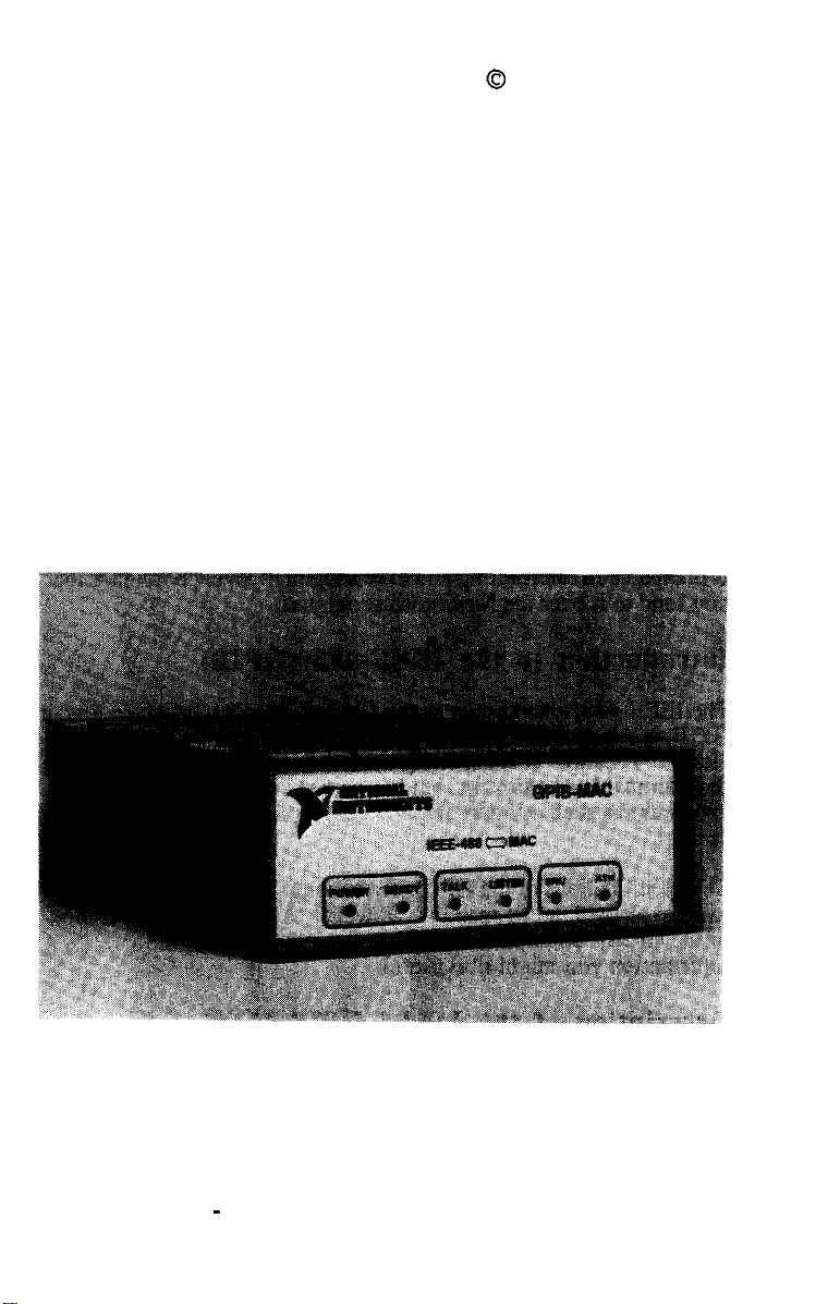
Physical Specifications
The GPIB-MAC, shown in the following figure, is housed in a
structural foam injection molded case. The unit can be rack mounted
or placed on a table.
Model GPIB-MAC
2
SECTION ONE - INTRODUCTION
Page 15
November 1985
0
National Instruments
Ouick Reference Chart.
On the back panel of the GPIB-MAC is a reference chart that
contains the information you need to configure the rear panel
switches of the GPIB-MAC. More detailed configuration
information is included in Section Two.
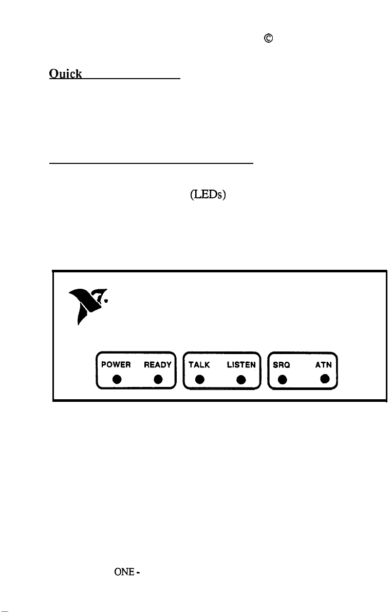
The Model GPIB-MAC Front Panel
The front panel of the GPIB-MAC is shown in the following figure.
The six light emitting diodes (LEDs) show the current status of the
GPIB-MAC.
3
SECTION
NATIONAL
INSTRUMENTS
IEEE-488 (MAC
[‘-p*ll’;“~][^;“l
Front Panel of the GPIB-MAC
ONE -
INTRODUCTION
GPIB-MAC
Page 16

0
November 1985
The following table shows what each LED indicates when lit.
National Instruments
LED
POWER
READY
TALK
LISTEN
ATN
SRQ
PurDose
indicates power is on.
indicates that the power-on self-test has passed
successfully and unit is ready to operate.
indicates that the GPIB-MAC is currently
addressed to Talk on the GPIB.
indicates that the GPIB-MAC is currently
addressed to Listen on the GPIB.
indicates that the GPIB signal line ATN* is
asserted (low).
indicates that the GPIB signal line SRQ* is
asserted (low).
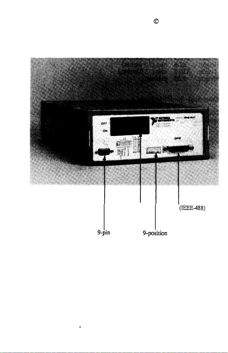
The Model GPIB-MAC Back Panel.
The
back panel of the GPIB-MAC is shown in the following figure.
The power connector, 9-position configuration switch, g-pin D-
subminiature connector, and GPIB (IEEE-488) port are shown.
4
SEaION
ONE - INTRODUCTION
Page 17
November 1985
0
National Instruments
g-pin
D-subminiature
Connector
Back Panel of the Model GPIB-MAC
5
SECTION ONE - INTRODUCTION
Power
Connector
9-position
Configuration
Switch
GPIB
(IEEE-488)
Port
Page 18

November 1985
0
National Instruments
Mechanical
Width:
Height:
Depth:
Weight:
&ecificationS
216.9 mm (8.5 inches)
88.4 mm (3.5 inches)
330.2 mm (13.0 inches)
5.25 pounds
Electrical Specifications
The GPIB-MAC is designed to operate under the following electrical
specifications.
Power:
115
volts AC or 230 volts AC; 50/60 Hz;
20 VA
Typical Current:
Fuse Type:
.09
amps AC
115
230
volts AC use
l/4
amp Fast
volts AC use l/8 amp Fast
6
SECTION ONE - INTRODUCTION
Page 19

0
November 1985
Section Two
-
Installation and
National Instruments
Configuration
Use this section to install and configure the GPIB-MAC. Then,
read Sections Three and Four to learn about how to program the
GPIB-MAC.
Inspection
Before you install the GPIB-MAC, inspect the shipping container
and its contents for damage. If damage appears to have been
caused in shipment, file a claim with the carrier. Retain the
packaging material for possible inspection or for reshipment.
If the equipment appears to be damaged, do not attempt to operate
it. Contact National Instruments for instructions.
Installation
There are four basic steps to installing the GPIB-MAC.
1. Verify voltage requirements
2. Configure GPIB-MAC rear panel switches
3. Connect cables
4. Turn power switch to On
Voltage Requirements
The
GPIB-MAC is shipped with the internal voltage selector switch
configured to operate on a standard 115 VAC power line.
If your setup requires 230 VAC, refer to Appendix C to learn how
to open the box to change the voltage selector switch.
7
SECTION TWO: INSTALLATION AND CONFIGURATION
Page 20
November 1985
0
National Instruments
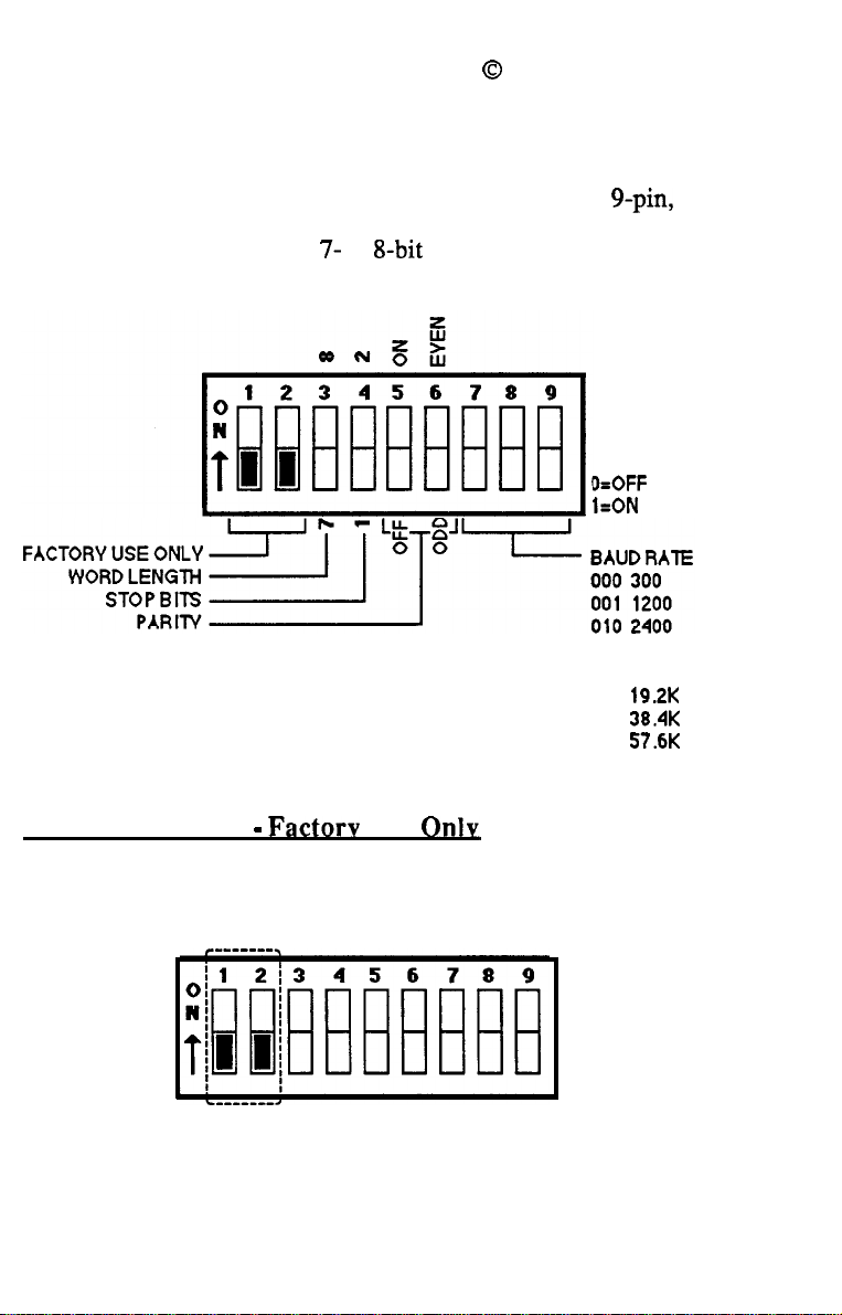
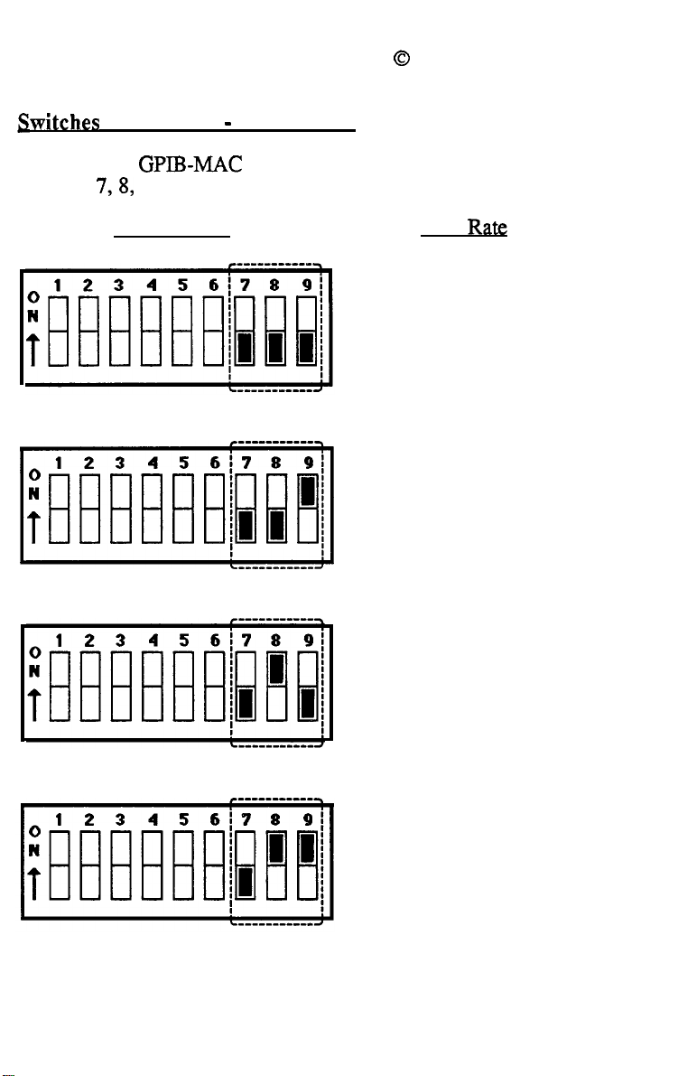
Configure the GPIB-MAC Rear Panel Switches
Configure the GPIB-MAC by setting the switches of the g-pin, rear
panel DIP switch. The following figure shows the switches
labeled for factory use only, 7- or
g-bit
word length, one or two
stop bits, odd/even or no parity, and baud rate.
D=OFF
l=ON
011
4800
100
9600
101
19.2K
110
38.4K
111
57.6K
GPIB-MAC DIP Switch
Switches 1 and 2 - Factorv Use
Only
Switch 1 and 2 are for factory use only and should always be
positioned in the off position as shown below.
Factory Use Only
8
SECTION TWO: INSTALLATION AND CONFIGURATION
Page 21
November 1985
0
National Instruments
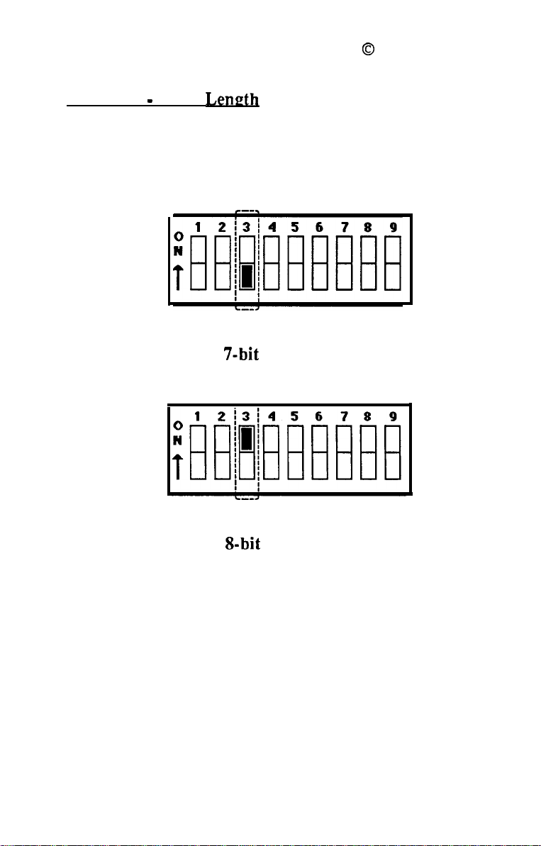
Switch 3
Configure the
setting switch 3. The off position indicates 7 bits, the on position
indicates 8.
-
Word
Length
GPIB-MAC
for a serial word length of 7 or 8 bits by
7-bit
Word Length
g-bit
Word Length
9
SECTION TWO: INSTALLATION AND CONFIGURATION
Page 22
0
National InstrumentsNovember 1985
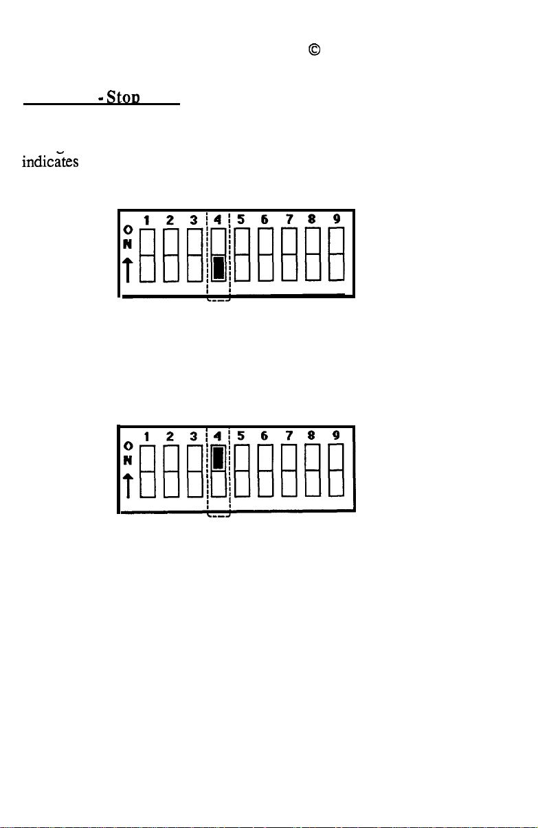
Switch 4
- StoD
Bits
Configure the GPIB-MAC for a stop bit length of 1 or 2 bits by
setting switch 4. The off position indicates 1 bit, the on position
indic&s
2.
1 Stop Bit
2 Stop Bits
10
SECTION TWO: INSTALLATION AND CONFIGURATION
Page 23
November 1985
0
National Instruments
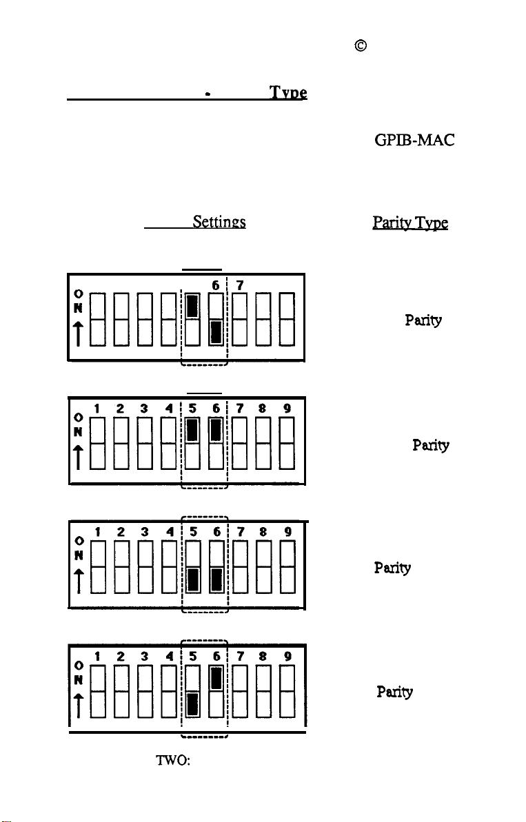
Switches 5 and 6 - Paritv
TVD~
The GPIB-MAC can transmit and receive serial data using odd
parity, even parity, or no parity. Configure the GPIB-MAC for
the correct parity according to the following figure. Note that
switch 5 indicates parity off. Switch 6 indicates parity odd or
even. If switch 5 is set to off, switch 6 is ignored.
Switch Settines
_
1 2 3 415
6i7
8 9
Parity
Odd
Even
Type
Parity
Parity
11
SECTION
Pa&y Inhibit
Parity
b_______.
Two:
INSTALLATION AND CONFIGURATION
Inhibit
Page 24
0
November 1985
.
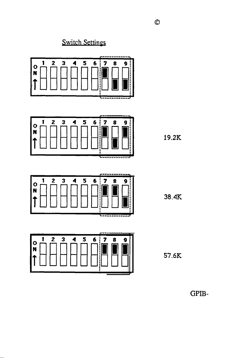
witches 7. 8. and 9 - Baud Rate
Configure the GPIB-MAC for the appropriate baud rate by setting
switches
7,8,
and 9 according to the following figures.
National Instruments
Switch Settings
~1
1200
Baud Rate
300
2400
4800
12
SECTION TWO: INSTALLATION AND CONFIGURATION
Page 25
November 1985
0
National Instruments
Baud
9600
19.2K
38.4K
57.6K
If you need more information on how the switches of the GPIB-
MAC
should be set, refer to Appendix G.
13
SECTION TWO: INSTALLATION AND CONFIGURATION
Page 26

November 1985
0
National Instruments
Connect Cables
You must connect three cables to operate the GPIB-MAC: the serial
cable, the power cable, and the GPIB cable. The three cables all
connect to the GPIB-MAC via the rear panel, as shown in the
following figure.
GPIB-MAC with Serial Cable, Power Cable, and GPIB
Cable
The power cord receptacle is located at the top left of the rear panel.
If 115 VAC is required, use the standard power cable supplied with
the unit. If 230 VAC is required, use a cable that is compatible with
both the GPIB-MAC power receptacle and the 230 VAC plug
configuration.
The GPIB cable should be connected to the 24-pin GPIB connector
on the lower right of the rear panel. The connectors can be piggybacked to add more GPIB devices to the bus. Connect the serial
cable to the
GPIB-MAC. Connect the other end of the cable to your Macintosh
modem port.
14
SECTION TWO: INSTALLATION AND CONFIGURATION
9-p&
D-subminiature connector on the back of the
Page 27

November 1985
0
National Instruments
Turn Power Switch to On
The power switch is located at the left of the power cord receptacle.
Turn the switch to On. There will be a slight delay while the unit
performs a self-test of all the internal circuitry. The test does not
affect devices connected to the GPIB-MAC. When the test
successfully completes, the BEADY LED comes on. If it does not,
verify your switch settings and the power connections. If the
BEADY LED still fails to come on, contact National Instruments.
Note - The rear panel switches are read by the fiiware only when
the unit is powered on. After changing switch settings, turn the
power switch off and back on for the change to take effect. Also,
the GPIB address of the GPIB-MAC at power on is 0 with
secondary addressing disabled. You can change these values after
power-on using a programming message.
15
SECTION TWO: INSTALLATION AND CONFIGURATION
Page 28
November 1985
0
National Instruments
Section Three - Programming the GPIB-MAC
This section shows how to program the GPIB-MAC by using
programming messages and data strings. It describes programming
messages, their format, and how they areprocessed, along with the
functions and function arguments that make up the programming
messages.
Programming Messages
You program the GPIB-MAC by sending it programming messages
(which are ASCII strings) and data strings by way of its serial port.
Programming Message Format
A
arguments (optional), followed by a carriage return (<CR>), a
linefeed (<LF>),
(<CR><LF>).
You may enter programming messages in any combination of
uppercase and lowercase letters.
Example of 3 Proaramming Message
The following line of BASIC code:
contains the function name
programming message tells the GPIB-MAC to clear the devices at
GPIB addresses 3 and 4. PRINT #l is the BASIC command to
send characters to the serial port after the serial port has been opened
with the “OPEN COM...” statement. In this example, BASIC
automatically sends a
17
amming message consists of a function name, one or more
progr
or a carriage return followed by a
PRINT
<CR>,
SECTION THREE - PROGRAMMING THE GPIB-MAC
#l,“clr 34”
clr
and the arguments 3 and 4. This
so it is not necessary to include it here.
linefeed
Page 29

November 1985
0
National Instruments
The cmd
string which may contain 7- or
Example ef 1~
The following lines of BASIC code:
contain the function name
“IN;CI;“.
write to the device at primary address 2.
“IN;CI;” is the data string which contains the data
on the GPIB. In this case, a
following each print string, so, again, it is not necessary to include it
here.
and
wrt
programming messages are followed by a data
ProFamming
PRINT # 1,
PRINT
This programmin
g-bit
data
Message with Data String
“wrt 2”
#l, ‘TN;CI;”
wrt, the
g
<CR>
argument 2, and the data string
message is telling the GPIB-MAC to
wrt
will send out
is automatically sent by BASIC
How Messages are Processed
g
The GPIB-MAC processes a programmin
line basis. The GPIB-MAC buffers the entire message, interprets
the function name and arguments, then executes the message.
message on a line-by-
The data portions of the
on a line-by-line basis. The data immediately following a
cmd are
sent directly to the GPIB.
wrt
and
cmd
functions are not processed
wrt
and a
Function Names
The function names have been selected to indicate each function’s
purpose, thereby making your programs easy to understand.
However, if you wish to reduce some overhead in your program
and do not mind giving up these advantages, you may use only as
much of the function name as is necessary to distinguish it from
other functions. This abbreviated form of the function name is
shown in
of the function descriptions.
18
boldface in the
SECTION THREE - PROGRAMMING THE GPIB-MAC
function tables and in the syntax portions
Page 30

November 1985
0
National Instruments
For example, the
wait
function may be called using either of the
next two statements:
PRINT
PRINT
#l,
#l,
“wait
“wa
\x5000”
\x5000”
Function Argument Delimiters
When you type in a function, separate the
function name with at least one space. Separate each additional
argument with at least one space or a comma.
In the syntax portions of the function descriptions in Section Four
the square brackets
(n)
are optional. If you want to include optional
information, you do not need to type the brackets, only the
information inside the brackets.
Abbreviations for Arguments
The function descriptions in Section Four use abbreviations for
some arguments. They are as follows:
addr a GPIB address
alist one or more addrs
boo1
a boolean value: 1 = true, on, or enable
0 = false, off, or disable
fmt
argument from the
GPIB Address
Each device on the GPIB has a GPIB address. The GPIB-MAC’s
address is 0 at power on and may be changed using the
caddr
function. Refer to the manuals of your GPIB devices to learn their
addresses. You will need to know these when you begin to
program the GPIB-MAC.
Only the lower five bits of each GPIB address are significant. These
bits may be in the range from 0 through 30 for both the primary and
the secondary address. For example, the binary value 01100010
(decimal 98) is interpreted as decimal 2.
19
SECTION
THREFi -
PROGRAMMING THE GPIB-MAC
Page 31

November 1985
The following examples all specify a primary address of 0 and a
secondary address of 2. A plus sign
address from the secondary address. The listen address is 32
(primary address plus
plus
64),
and the secondary address is 2 or 98, which are
equivalent. The next paragraph explains the \x notation.
0+2
32),
the talk address is 64 (primary address
or
0+98
or
32+98
0
National Instruments
(+)
separates the primary
or
O+\x62
Numeric String Argument
Another type of argument is a numeric string.
represents an integer, which you may express using decimal, octal,
or hexadecimal digits. To specify an octal integer, precede it with a
backslash
backslash x ox) or backslash X
Each of the following numeric strings represents the decimal integer
value 112:
The GPIB address argument described previously under “GPIB
Address” consisted of one or two numeric strings.
0).
To specify a hexadecimal integer, precede it with a
OX).
112
\160
\x70
A numeric string
Status Information
The function descriptions in Section Four explain that the GPIB-
MAC “records” specific status and error information. This means
that it stores that information in its memory so that the status
information is available to you when you request it.
The function descriptions also explain that the GPIB-MAC “returns
to you” certain information. This means that the GPIB-MAC sends
information to you over the serial port. You then read this
information from your serial port
20
SECTION THREE - PROGRAMMING THE GPIB-MAC
Page 32

November 1985
0
National Instruments
Serial Port Error Handling
The GPIB-MAC continuously monitors the serial port for transmission errors. If it encounters an error in the serial data, the
MAC records the error. You can program the GPIB-MAC to stop
processing the programming message when a serial port error
occurs or to ignore these serial port errors. Refer to the spign
function.
GPIB-
GPIB Read
and’write
Termination Method (END
and EOS)
You program the GPIB-MAC to Talk in order to send data messages
over the GPIB, and to Listen in order to receive data messages from
the GPIB.
The IEEE-488 specification defines two ways that GPIB Talkers
and Listeners may identify the last byte of data messages: END and
EOS. The two methods permit a Talker to send data messages of
any length without the Listener(s) knowing in advance the number
of bytes in the transmission.
* END message
* EOS character
the Talker asserts the EOI (End or Identify)
signal while the last data byte is being
transmitted. The Listener stops reading when
it detects a data byte accompanied by EOI.
the Talker sends an EOS (end-of-string)
character at the end of its data suing. The
Listener stops receiving data when it detects
the EOS character. Either a ‘I-bit ASCII
character or a full
used.
g-bit
binary byte may be
The two methods can be used individually or in combination. It is
important that the Listener be configured to detect the end of a
transmission.
21
SECTION THREE - PROGRAMMING THE GPIB-MAC
Page 33

November 1985
0
National Instruments
The GPIB-MAC always terminates GPlB
rd
operations on the END
message. Using the eos and eot functions, you may change the
other default GPIB read and write termination methods.
Default Settings
The following tables list power-on characteristics of the GPIB-MAC
and the functions you can use to change those characteristics.
SERIAL PORT CHARACTERISTICS
Characteristic
echo bytes to serial port
ignore serial port errors
send
XON/XOFF
recognize
XON/XOFF
GPIB CHARACTERISTICS
Characteristic
primary/secondary address
end-of-string modes
Power-on Value
no
Yes
no
no
power-on Value
pad=O,sad=none
none
send END on writes
ist bit setting
yo”
GPIB-MAC is System Controller yes
I/O timeout
serial poll timeout
10
.l set
set
Function
echo
spign
xon
xon
Function
caddr
eos
cot
ist
IX
IlIlO
tIll0
List of Functions by Group
The
GPIBMAC
GPIB
functions, Serial Port functions, and General Use functions.
SECTION THREE - PROGRAMMING THE GPIB-MAC
22
functions are divided into three main groups:
Page 34

November 1985
0
National Instruments
GPIB Functions
The
GPIB
functions are divided into subgroups as shown. The
subgroups are listed with the most frequently used groups first.
Often, the I/O and bus management functions are the only ones you
need.
I/O FUNCTIONS
Function
RD count,address
WRT count,address list
data
MANAGEMENT FUNCTIONS
BUS
Function
CLR address list
LOC address list
TRG address list
GPIB INITIALIZATION FUNCTIONS
Function
CADDR address
EOS modes,eoschar
EOT on/off
ONL on/off
RSC on/off
TM0
values
ti
Read data
write data
Pupose
Cl;;
sgzed
device(s)
Trigger selected device(s)
Puipose
Change the GPIB address
of the GPIB-MAC
Change/disable GPIB EOS
termination mode
Enable/disable END
message on
GPIBwrites
Place the GPIB-MAC online/
offline
Request or release System
Control
Change or disable time limit
SECTION THREE - PROGRAMMING THE
23
GPIEbMAC
Page 35

November 1985
0
National Instruments
SERIAL POLL FUNCTIONS
Function
RSP
address list
RSV
status byte
LOW-LEVEL CONTROLLER FUNCTIONS
Function
CAC mode
CMD count
commands
GTS mode
PCT address
SIC time
SRE on/off
PARALLEL POLL
Purpose
Request (conduct) a serial poll
Request service and/or set or
change the serial poll status
byte
Pur_Dose
Become active controller
Send IEEE-488 commands
Go from Active Controller to
Standby
Pass Control
Send interface clear
Set/clear remote enable
FUNCTIONS
Function
IST on/off
Purpos!2
Set or clear individual status
bit for use in GPlB-MAC
response to Parallel Polls
PPC values
PPU address list
RPP
Parallel Poll Configure
Parallel Poll Unconfigure
Request (conduct) a Parallel
Poll
SECTION THREE - PROGRAMMING THE GPIB-MAC
24
Page 36

November 1985
Serial Port Functions
SERIAL PORT INITIALIZATION FUNCTIONS
0
National Instruments
Function
ECHO
SPIGN on/off
XON modes
on/off
Purpose
Echo characters received from
serial port
Ignore serial port errors
Change serial port
XON/XOFF protocol
General Use Functions
GENERAL USE
Function
IDMAC
STAT modes
WAIT mask
FUNCTIONS
Purpwl
Identify system
Return GPIB-MAC status
Wait for selected event
List of Functions in Alphabetical Order
The following is an alphabetical list of all functions.
GPIB-MAC FUNCTIONS
Function
CAC mode
CADDR address
CLR address list
CMD count
commands
ECHO on/off
25
SECTION THREE - PROGRAMMING THE GPIB-MAC
m
Become active controller
Change GPIB address of the
GPIB-MAC
Clear specified device(s)
Send
GPIB
Echo characters received from
serial port
commands
Page 37

November 1985
GPIB-MAC FUNCTIONS (CONTINUED)
0
National Instruments
EOS modes,eos
EOT on/off
GTS mode
IDMAC
IST set/clear
LOC address list
ONL on/off
PCT address
PPC values
PPU address list
RD count,address
RPP
RSC on/off
RSP address list
RSV serial poll
SIC time
SPIGN on/off
SRE on/off
STAT modes
TM0
values
TRG address list
WAIT mask
WRT count,address list
data
XON modes
Change/disable GPIB EOS
termination mode
Enable/disable END
message on
GPIB
writes
Go from Active Controller to
Standby
Identify system
Set or clear individual status
bit for use in GPIB-MAC
response to Parallel Polls
Go to Local
Place the GPlB-MAC
online/offline
Pass Control
Parallel Poll Configure
Parallel Poll Unconfigure
Read data
Request (conduct) a Parallel
Poll
Request or release System
Control
Request (conduct) a serial poll
Request service/set or change
the serial poll status byte
Send interface clear
Ignore serial port errors
Set or clear remote enable
Return GPIB-MAC status
Change or disable time limit
Trigger selected device(s)
Wait for selected event
write data
Change serial port
XON/XOFF protocol
26
SECTION THREE - PROGRAMMING THE GPIB-MAC
Page 38

November 1985
0
National Instruments
Section Four - Functions
This section contains descriptions of functions which you use to
program the GPIB-MAC. These functions are in alphabetical order
and are formatted to provide you a handy reference.
Points to Remember
1.
The programming examples for each function description are in
Microsoft BASIC version 2.0.
2.
In the syntax portion of the function descriptions, arguments
enclosed in brackets are optional. Do not enter the brackets as
part of your argument.
3.
Terminate each programming message with a catriage return
(<CR>), a linefeed
linefeed (<CR><LF>).
the syntax portions of the function descriptions. In the program-
ming examples, the BASIC PRINT # statement automatically
sends a carriage return at the end of the string, so a carriage
return is not placed there explicitly.
(<IF>),
or a carriage return followed by a
The terminator is denoted by
<CR>
in
4.
To send more than one programming message per PRINT
statement, embed a <CR> (denoted by
(denoted by CHR$( 10))in the statement. For example, to send
the two programming messages “send interface clear” and “send
remote enable,” you could use either of these two sequences:
PRINT #l,“sic”
PRINT
PRINT # 1
5.
For all examples, the communications port has been assigned to
file number 1
27
SECTION FOUR - FUNCTIONS
#l,“sre
or
(#l)
by the BASIC OPEN
1”
,“sic”+CHR$( 13)+“sre
CIIR$(
“COM...”
13)) or
1”
statement.
<LF>
Page 39

November 1985
6.
It is necessary for you to send only enough characters of the
0
National Instruments
function name to distinguish it from other functions. Those
characters are shown in boldface in the syntax portion of each
function description.
‘7.
I/O and bus management functions meet most of your needs. In
the descriptions that follow, these frequently used functions are
marked with an asterisk
(*).
28
SECTION FOUR - FUNCTIONS
Page 40

November 1985
cat -
Become Active Controller
cat:
Low-level Controller function
0
National Instruments
Syntax:
Purpose:
Remarks:
cat
[bool]cCR>
You use
Controller to Active Controller and when the I/O and bus
management functions do not meet the needs of your
device.
GPIB than the I/O and bus management functions.
If the argument
immediately; that is, it takes control asynchronously. If
the argument
after any handshake that is in progress completes; that is,
it takes control synchronously.
If you call
returns to you the current controller status, which is 0 if
the GPIB-MAC is m the Active Controller
GPIB-MAC h the Active Controller.
If call
CIC, the GPIB-MAC records the ECIC error.
The power-on Controller status of the GPIB-MAC is
Idle Controller.
cat
to change the GPIB-MAC from Standby
cat
allows you more precise control over the
boo1
is 1, the GPIB-MAC takes control
boo1
is 0, the GPIB-MAC takes control
cat
without an argument, the GPIB-MAC
and1
if the
cat
with an argument and the GPIB-MAC is not
Refer also to
29
SECTION FOUR - FUNCTIONS
gts
and sic.
Page 41

November 1985
Examples:
0
National Instruments
1.
PRINT#l,“cac
PRINT # 1
2.
1”
,“cac 0”
3. PRINT #l,“CAC”
response:
lcCRxLF>
‘Take control immediately.
‘Take control synchronously.
‘Are we the active controller?
.
..yes...we’re
CAC
SECTION FOUR - FUNCTIONS
30
Page 42

November 1985
0
National Instruments
caddr
cad&
Syntax:
Purpose:
Remarks:
-
Change GPIB Address of the GPIB-MAC
Initialization function
cad&
You use
change the GPIB address of the GPIB-MAC.
The argument
new GPIB address for the GPIB-MAC. addr consists
of a primary address and an optional secondary address.
The secondary address is separated from the primary
address by a plus sign
expressed as numeric strings.
Only the lower five bits of each address are significant.
These bits may be in the range from 0 through 30 for
both the primary and the secondary address. Therefore,
the binary value 01100010 (decimal 98) is interpreted as
decimal 2.
The following examples all specify a primary address of
0 and a secondary address of 2. The listen address is
32, the talk address is 64, and the secondary address is 2
or 98, which are equivalent.
[addr]&R>
caddr
at the beginning of your program to
addr
is a device address that specifies the
(+).
Both addresses are
0+2
If you specify a primary address without a secondary
address, secondary addressing is disabled.
If you call caddr without an argument, the GPIB-MAC
returns to you its current GPIB address.
The address assigned by this function remains in effect
until you call caddr again, call onl, or you turn off the
GPIB -MAC.
31
SECTION FOUR - FUNCTIONS
or
0+98
or
32+98
or
O+\x62
Page 43

November 1985
The power-on default is 0 with secondary addressing
disabled.
Examples:
0
National Instruments
1~
PRINT
2. PRINT
3. PRINT #l,“CADDR”
response:
#l,“caddr 0+22”
#l,“CADDR
lcCRxLF>
1”
‘Give GPIB-MAC a primary address
‘of 0 and a secondary address of 22.
‘Change GPIB-MAC primary
‘address to 1 and disable secondary
‘addressing.
‘Return current GPIB-MAC address.
SECTION FOUR - FUNCTIONS
32
Page 44

November 1985
0
National Instruments
clr - Clear. Specified Device
Bus
Clr:
Syntax:
Purpose:
Remarks:
Management function
clr [alist]cCR>
You use
the specified devices. For example, a multimeter might
require that you send it either the GPIB Device Clear or
Selected Device Clear command to change its function,
range, and trigger mode back to its default setting. Use
clr to do this.
The argument
commas or spaces. addrs are device addresses that
specify the GPIB addresses you wish to clear. alist
may consist of only one addr.
A device address consists of a primary address and an
optional secondary address. The secondary address is
separated from the primary address by a plus sign
Only the lower five bits of each address are significant
These bits may be in the range from 0 through 30 for
both the primary and the secondary address. Therefore,
the binary value 01100010 (decimal 98) is interpreted as
decimal 2.
clr
to reset the internal or device functions of
alist
is a list of addrs separated by
*
(+).
The following examples all specify a primary address of
0 and a secondary address of 2. The listen address is
32, the talk address is 64, and the secondary address is
or 98, which are equivalent.
0+2
If you call
devices specified in
If you call
devices (Device Clear).
33
SECTION FOUR - FUNCTIONS
clr
clr
or
0+98
or
32+98
with
alist, the GPIB-MAC
alist
(Selected Device Clear).
without
alist, the GPIB-MAC
or
O+\x62
clears only the
clears all
Page 45

November 1985
If this is the first function you call that requires GPIB
controller capability, and you have not disabled System
Controller capability with csc, the GPIB-MAC sends
Interface Clear
Remote Enable.
Refer to Appendix D for more information on clearing
devices.
Refer to Appendix B for more error information.
Examples:
0
National Instruments
(IX)
to make itself CIC. It also asserts
1. PRINT
#l,“clr 14+30,16+12,18,3+26,6”
2. PRINT #l,“CLR”
*
frequently used function
‘Selectively clear
‘5 devices.
‘Issue Device Clear
‘to all devices.
34
SECTION FOUR - FUNCTIONS
Page 46

November 1985
cmd - Send GPIB Commands
cm&
Specialized Controller function
0
National Instruments
Syntax: cmd
Purpose:
Remarks:
[#count]<CR>
commands<CR>
You
use
cmd
when the I./O and bus management
functions do not meet the needs of your device.
allows you precise control over the GPIB. For example,
in applications that require command sequences not sent
by other functions,
sequence of interface messages (commands) over the
GPIB .
The argument
number sign
command bytes (interface messages) to send, which is a
number between 1 and 255. The number of command
bytes must not include the carriage return or
you include to indicate the end of the programming
message.
The argument
These commands are represented by their ASCII
character equivalents. For example, the GPIB Untalk
(UNT)
Refer to Example 2 to learn how to send non-printable
characters.
command is the ASCII character underscore C).
cmd allows you
count
(#).
commands
is a numeric string preceded by a
#count specifies the number of GPIB
is a list of GPIB commands.
to transmit any
cmd
linefeed
that
If you call
recognizes the end of the command string when it sees
a
<CR>
command string contains a
However, a
would be unusual since neither of these is a defmed
GPIB command.
SECTION FOUR - FUNCTIONS
35
or
cmd
<LF>.
<CR>
without
#count, the
GPIB-MAC
#count is required only if the
<CR>
or an
(LF>
or an
d3;>
in the command string
character.
Page 47

November 1985
The GPIB commands, or interface messages, are listed
in Appendix A. They include device talk and listen
addresses, secondary addresses, messages, device clear
and trigger instructions, and other management
messages.
0
National Instruments
Do not use
cmd
to send programming instructions to
devices. Use rd and wrt to send or receive device
programming instructions and other device dependent
information.
The cmd
-
-
operation terminates when:
the GPIB-MAC successfully transfers all commands,
the GPIB-MAC detects an error (GPIB-MAC is not
CIC),
-
the
I/O
time
limit
is exceeded,
-
the Take Control
(TCT)
command is in your
command string and is sent to the GPIB.
-
the Interface Clear
(IX)
message is received from
System Controller (not the GPIB-MAC).
After cmd terminates, the GPIB-MAC records the
number of command bytes it actually sent.
If an event in
the above list occurs, the count may be less than
expected
36
If you specify #count and enter more than #count
command bytes, the excess command bytes up to the
<CRXLP>
are discarded.
If you call cmd and the GPIB-MAC is not CIC, the
GPIBMAC
SECTION
FOUR -
records the ECIC error.
FUNCTIONS
Page 48

November 1985
If the GPIB-MAC is CIC but not Active Controller, it
takes control and asserts ATN before sending the
command bytes. It remains Active Controller afterward.
Refer to Appendix A to convert hex values to ASCII
characters.
Examples:
0
National Instruments
1. PRINT
#l,“cMD”
‘Program device at address 11 to
‘listen and GPIB-MAC at address 0
‘to talk.
PRINT #l,“+@”
‘Device listen address is 43 or
‘ASCII + and GPIB-MAC talk
‘address is 64 or ASCII
PRINT # 1,’
PRINT # 1
,‘I ABCDE”
‘WI-W
Write the string
‘device at address 11.
2. PRINT #l,“cmd”-tCHR$(13)+”
‘Pass control to device 23
‘(CHR$(9)=TCT
“ABCDE”
?W”+CHR$(9)
command).
@.
to
37
SECTION FOUR - FUNCTIONS
Page 49

November 1985
0
National Instruments
echo - Echo Characters Received from Serial
Port
echo:
Syntax:
Purpose:
Remarks:
Examples:
Note:
1. echo
The following examples show commands as you would
enter them at a terminal.
Serial Port function
echo [bool]<CR>
You use
on the Macintosh while connected to the GPIB-MAC and
you wish to echo what you type on the screen.
If the argument
serial port are echoed back to the serial port
argument
argument
disabled, characters will not be echoed until this
command has been completely processed, i.e., the
programming message will be echoed
If you call echo without an argument, the GPIB-MAC
returns the current setting.
l&R>
echo
when a terminal emulation program is run
boo1
is 1, characters received from the
If the
boo1
is 0, characters are not echoed. If the
boo1
is 1 and echoing was previously
Turn on character echoing.
m
2. ECHO O<CR>
3.
echo&R>
response:
38
SECTION FOUR - FUNCTIONS
OcCRxLF>
‘Disable character echoing.
What is the current echo status?
(character echo is disabled)
Page 50

0
November 1985
National Instruments
eos - Change/Disable GPIB EOS Termination
Mode
eos: Initialization function
Syntax: eos [[R][X][B] eoschar]<CR>
or
eos D<CR>
Purpose:
Remarks:
You use eos at the beginning of your program if you
wish to use an eos mode when you transfer data to and
from the GPIB. eos tells the GPIB-MAC when to stop
reading information from the
the GPIB-MAC to tell other devices that it is finished
writing information to the GPIB. eos defines a specific
character, end-of-string (EOS), to be recognized as a
string terminator.
The arguments R, X, B, and D specify GPIB termin-
ation methods. They enable or disable the corresponding
eos mode. If a particular letter is specified, the corres-
ponding eos mode is enabled. If it is not specified, the
corresponding eos mode is disabled.
eoschar is a numeric string which represents a single
ASCII character. For example, 10 represents the ASCII
linefeed character.
DATA TRANSFER TERMINATION METHODS
pescrintioq
REOS - terminate read when EOS is detected.
GPIB.
eos also enables
Letter
R
XEOS - set EOI with EOS on write functions. X
BIN - compare all 8 bits of EOS byte rather than
low 7 bits (all read and write functions).
DISABLE - disable all eos modes.
39
SECTIONFOUR-FUNCTIONS
B
D
Page 51

November 1985
Methods R and B determine how GPIB read operations
performed by the GPIB-MAC terminate. If Method R
alone is chosen, reads terminate when the low 7 bits of
the byte that is read match the low 7 bits of the EOS
character. If Methods R and B are chosen, a full
comparison is used.
Methods X and B together determine when GPIB write
operations performed by the GPIB-MAC send the END
message. If Method X alone is chosen, the END
message is sent automatically with the EOS byte when
the low 7 bits of that byte match the low 7 bits of the
EOS character. If Methods X and B are chosen, a full
g-bit comparison is used.
Note that defining an EOS byte for the GPIB-MAC does
not cause the GPIB-MAC to insert that byte into the data
string when performing GPIB writes. To send the EOS
byte, you must include it in the data string that you send
following the
By default, no eos modes are enabled.
wrt
programming message.
0
National Instruments
g-bit
If you call
eos
MAC records the EARG error.
If you call eos without an argument, the GPIB-MAC
returns to you the current eos settings.
The assignment made by this function remains in effect
until you call eos again, call
GPIB-MAC.
Refer to the GPIB Read and Write Termination
explanation in Section Three.
40
SECTION FOUR - FUNCTIONS
with B alone as an argument, the GPIB-
onl,
or you turn off the
Page 52

November 1985
Examples:
0
National Instruments
1.
PRINT
#l,“eos R,B,lO”
‘Terminate read when
‘detected; compare all 8 bits; do
‘not send EOI with
PRINT
#l,“rd
10
5”
‘Read 10 bytes from device 5 into
‘serial port buffer.
RESP$=INPUT$( lO,#l)
‘Input 10 bytes from serial port
‘buffer.
LINE INPUT #l,COUNT$
CNT%=VAL(COUNT$)
PRINT COUNT$;“bytes were read from
‘Input string that indicates number
‘of bytes actually read from GPIB
‘of bytes that were read from the
‘GPIB.
2. PRINT
#l,“EOS X,13”
‘Tell GPIB-MAC on wrt, send
‘EOI
‘terminate when <CR> is
‘detected; compare 7 bits.
PRINT
#l,“wrt #lO 5”
‘GPIB-MAC sends EOI with
‘<CR> (CHR$(13))
‘listeners that this is the last byte
‘of data.
PRINT
#1,“012345678”+CHR$(13)
with
GPKB”
<CR>;
<LF>
is
<LF>.
‘Print number
on rd, do not
to tell
3. PRINT #l,“eos”
response:
41
SECTION
X,13cCRxLF>
FOUR -
‘What are the current EOS
‘settings?
FUNCTIONS
Page 53

0
November 1985
National Instruments
eot - Enable/Disable END Message on GPIB
Writes
cot:
Initialization function
eot[
boo11
Syntax:
<CR>
Purpose:
Remarks:
You use eot at the beginning of your program if you
wish to change how the GPIB-MAC terminates GPIB
writes. Using eot, you tell the GPIB-MAC to automatically send or not send the GPIB END message with
the last byte that it writes to the GPIB.
If the argument
sends the END message with the last byte of each
If the argument
on default is 1.
If you call eot without an argument, the GPIB-MAC
returns to you a 1 to indicate END termination is
currently enabled, or a 0 to indicate END termination is
currently disabled
The assignment made by
call eot again, call onl, or you turn off the GPIB-MAC.
The GPIB-MAC sends the END message by asserting
the GPIB EOI signal during the last byte of a data
transfer. eot is used primarily to send variable length
data.
Refer to the GPIB Read and Write Termination
explanation in Section Three.
boo1
is 1, the GPIB-MAC automatically
boo1
is 0, END is not sent. The
eot
remains in effect until you
wrt.
power-
SECTION FOUR - FUNCTIONS
42
Page 54

November 1985
Examples:
0
National Instruments
1. PRINT
2. PRINT
PRINT
PRINT #
#l,“eot 0”
#l,“EOT
#l,“WRT
1,”
ABCDE”
3. PRINT #l,“eot”
response:
lcCRxLF>
1”
3”
‘Disable END termination.
‘Send END with last byte.
Write data to device at address 3.
The EOI line is automatically
‘asserted when the last byte (the
letter E) is sent to tell the
‘Listeners it is the last byte of data.
What is the current EOT setting?
(END termination is currently
enabled)
43
SECTION FOUR - FUNCTIONS
Page 55

November 1985
0
National Instruments
gts - Go from Active Controller to Standby
gts: Specialized Controller function
Syntax: gts [bool]cCR>
Purpose:
Remarks:
You use
Controller to Standby Controller. You use gts when the
I/O and bus management functions do not meet the needs
of your device. For example, you use gts if you wish to
allow two external devices to talk to each other directly.
The GPIB-MAC can selectively participate in the hand-
shake of the data transfer and hold off the handshake
when it detects the END message. The GPIB-MAC can
then take control synchronously without possibly
corrupting the transfer.
If the argument
enabled. If the argument
handshaking is not performed.
If you call gts without an argument, the GPIB-MAC
returns to you the current controller status: CSB,O if the
GPIB-MAC is in Standby without shadow handshaking;
CSB,l
handshaking; CAC if the GPIB-MAC is CIC but is not
in Standby, i.e., it is the Active Controller; and
the GPIB-MAC is not the CIC, i.e., is an IDLE
Controller.
gts causes the GPIB-MAC to go to the Controller
Standby state and to unassert the ATN signal if it is
initially the Active Controller. gts permits
devices to transfer data without the GPIB-MAC
participating in the transfer.
gts
to change the GPIB-MAC from Active
boo1
is 1, shadow handshaking is
boo1
is 0, shadow
if the GPIB-MAC is in Standby with shadow
COLE
GPIB
if
44
SECTION FOUR - FUNCTIONS
Page 56

November 1985
If you enable shadow handshaking, the GPIB-MAC
participates in the data handshake as an Acceptor without
actually reading the data It monitors the transfers for the
END (EOI or end-of-string character) message and holds
off subsequent transfers. This mechanism allows the
GPIB-MAC to take control synchronously on a
subsequent operation such as
Before performing a gts with a shadow handshake, you
should call eos to establish the proper end-of-string
character or to disable the EOS detection if the
string character used by the talker is not known.
If you call gts with an argument and the GPIB-MAC is
not CIC, the GPIB-MAC records the ECIC error.
0
National Instruments
cmd
or
rpp.
end-of-
Refer also to
Examples:
1.
PRINT
2. PRINT
3. PRINT #l,“gts”
response:
#l,“gts 0”
#l,“GTS
CSB,lcCRxLF>
cat.
‘GTS without shadow handshaking.
1” ‘GTS with shadow handshaking.
What is the standby status?
(GPIB-MAC is in standby
status with shadow
handshaking)
45
SECTION FOUR - FUNCTIONS
Page 57

November 1985
0
National Instruments
idMAC -
idMAC:
Syntax: idMAC<CR>
Purpose:
Remarks:
Example:
PRINT # 1
response: GPIB-MAC, Rev.
Identify System
General Use function
You use
of your software, or if you wish to know how much
RAh4
The identification is returned in three strings. The first
two strings identify the company product model, the
software revision level, and a copyright notice. The
third string identifies the number of bytes of RAM in the
GPIB-MAC.
idMAC if you
is installed in your GPIB-MAC.
,“idhIAC”
(c)1985 National
2K bytes
RAMcCR>cLF>
wish to know the revision level
‘Get system identification
A.OcCRxLF>
InstrumentscCR>cLF>
SECTION FOUR - FUNCTIONS
46
Page 58

November 1985
0
National Instruments
ist - Set or Clear Individual Status Bit
ist:
Parallel Poll function
Syntax:
Purpose:
Remarks:
Examples:
1. PRINT
2. PRINT
3. PRINT #l,“ist”
ist
[bool]&R>
You use ist when the GPIB-MAC participates in a
parallel poll that is conducted by another device that is
Active Controller.
If the argument
status bit is set to 1. If the argument
GPIB-MAC’s individual status bit is cleared. The
power-on default is 0.
If you call ist without an argument, the GPIB-MAC
returns the value of its individual status bit.
Refer also to
#l,“ist
#l,“IST 0”
1”
boo1
is 1, the GPIB-MAC’s individual
ppc
and Appendix F.
‘Set ist to 1.
‘Clear ist to 0.
‘What is ist set to?
boo1
is 0, the
response:
SECTION FOUR - FUNCTIONS
47
OcCR>cLF>
(ist is currently 0)
Page 59

November 1985
lot -
Go to Local
lot: Bus Management function
lot
[
alist]
Syntax:
<CR>
0
National Instruments
*
Purpose:
Remarks:
You use
this mode you can program the device from its front
panel.
program mode before it can be programmed from the
GPIB, the GPIB-MAC automatically puts the device in
remote program mode. You then use
devices to local program mode.
The argument
commas or spaces.
specify the GPIB addresses of the devices you wish to
return to local mode.
A device address consists of a primary address and an
optional secondary address. The secondary address is
separated from the primary address by a plus sign
Only the lower five bits of each address are significant
These bits may be in the range from 0 through 30 for
both the primary and the secondary address. Therefore,
the binary value 01100010 (decimal 98) is interpreted as
decimal 2.
The following examples all specify a primary address of
0 and a secondary address of 2. The listen address is
32, the talk address is 64, and the secondary address is 2
or 98, which are equivalent.
lot
to put a device in local program mode. In
Since a device must usually be placed in remote
lot
to return
alist
is a list of
addrs are
addrs
separated by
device addresses that
(+).
0+2
If you call
specified device(s) in local mode using the Go To
Local (GTL) command
SECTION FOUR - FUNCTIONS
48
lot
or
with
0+98
or
32+98
alist,
the GPIB-MAC places the
or
O+\x62
Page 60

November 1985
If this is the first function you call that requires GPIB
controller capability, and you have not disabled System
Controller capability with
Interface Clear
Remote Enable. If you passed control to some other
GPIB device, control must be passed back to you or you
must send IPC to make yourself CIC before making this
call. Otherwise, the ECIC error will be posted.
0
National Instruments
rsc,
the GPIB-MAC sends
(IX)
to make itself CIC. It also asserts
If you
call~loc
System Controller, the GPIB-MAC returns all devices
to local mode by unasserting REN and asserting it
again. If you call
MAC is not System Controller, the GPIB-MAC records
the ESAC error.
Refer to Appendix B for more error information.
Examples:
1. PRINT
2. PRINT
#l,“loc 6+22,4+23,7”
#l,“LOC’
* frequently used function
without
lot
without
alist,
and the GPIB-MAC is
alist
and the GPIB-
‘Put 3 devices in local mode.
‘Put all devices in local mode.
49
SECTION FOUR - FUNCTIONS
Page 61

0
November 1985
on1 -
Place the GPIB-MAC Online/Offline
onl: Initialization function
National Instruments
Syntax:
Purpose: You use
Remarks:
on1
[bool] <CR>
GPIB-MAC and the GPIB, or to reinitialize the GPIB-
MAC characteristics to their default values.
If the argument
online. If the argument
places itself offline. By default, the GPIB-MAC powers
up online, is in the Idle Controller state, and configures
itself to be the System Controller.
If you call
returns the current status of the GPIB-MAC, which is 0
if the GPIB-MAC is offline and 1 if the GPIB-MAC is
online.
Placing the GPIB-MAC offline may be thought of as
disconnecting its GPlB cable from the other GPIB
devices.
Placing the GPIB-MAC online allows the GPIB-MAC to
communicate over the GPIB, and also restores all GPIB-
MAC settings to their power-on values.
on1
to disable communications between the
boo1
is 1, the GPIB-MAC places itself
boo1
is 0, the GPIB-MAC
on1
without an argument, the GPIB-MAC
Refer to the Serial Port Characteristics table and the
GPIB Characteristics table in Section Three for the
GPIB-MAC power-on settings.
50
SECTION FOUR - FUNCTIONS
Page 62

November 1985
Examples:
0
National Instruments
1. PRINT
2. PRINT
#l,“onl
1”
#l,“ONL 0”
‘Put the GPIB-MAC online and
‘restore its power-on settings.
‘Put the GPIB-MAC offline to
‘prevent it from communicating
‘with the GPIB.
51
SECTION FOUR - FUNCTIONS
Page 63

November 1985
pet
- Pass Control
pet: Specialized Controller function
0
National Instruments
Syntax: pet
Purpose:
Remarks:
addr<CR>
You use
pet
to pass Controller-In-Charge (CIC)
authority from the GPIB-MAC to some other device.
The argument
addr
is the address of the device you wish
you wish to pass control to. addr consists of a primary
address and an optional address. The secondary
address is separated from the primary address by a plus
sign
(+).
Both address are expressed as numeric strings.
Only the lower five bits of each address are significant.
These bits may be in the range from 0 through 30 for
both the primary and the secondary address. Therefore,
the binary value 01100010 (decimal 98) is interpreted as
decimal 2.
The following examples all specify a primary address of
0 and a secondary address of 2. The listen address is
32, the talk address is 64, and the secondary address is 2
or 98, which are equivalent.
0+2
or
0+98
or
32+98
or
O+\x62
pet
passes CIC authority from the GPIB-MAC to the
device specified by addr. The GPIB-MAC automatically goes to Controller Idle State. It is assumed that
the target device has Controller capability.
If you call
pet
with an argument and the
not CIC, it records the ECIC error.
If you call
pet
without an argument, the GPIB-MAC
records the EARG error.
52 SECTIONFOUR-FUNCTIONS
GPIB-
MAC is
Page 64

November 1985
Example:
0
National Instruments
PRINT
#l,“pct 7+18”
‘Pass control to device with
‘primary address 7 and
‘secondary address 18.
53 SECTIONFOUR-FUNCTIONS
Page 65

November 1985
0
ppc - Parallel Poll Configure
Parallel Poll function
Ppc:
National Instruments
Syntax:
Purpose:
Remarks:
ppc addr,ppr,s [addr,ppr,s] [addr,ppr,s]...cCR>
You use
ppc
to configure specified devices to respond
to parallel polls in a certain manner.
addr
specifies the GPIB address of the device to be
enabled or disabled for parallel polls. addr consists of a
primary address and an optional secondary address. The
secondary address is separated from the primary address
by a plus sign
(+).
Both addresses are expressed as
numeric strings.
Only the lower five bits of each address are significant
These bits may be in the range from 0 through 30 for
both the primary and the secondary address. Therefore,
the binary value 01100010 (decimal 98) is interpreted as
decimal 2.
The following examples all specify a primary address of
0 and a secondary address of 2. The listen address is
32, the talk address is 64, and the secondary address is 2
or 98, which are equivalent.
0+2
or
0+98
or
32+98
or
O+\x62
The argument
specifying the data line on which to respond.
The argument s is either 0 or 1 and is interpreted along
with the value of the device’s individual status bit to
determine whether to drive the line true or false.
Each group of addr,ppr,s may be separated by either a
comma or space, just as any list of arguments.
SECTION FOUR - FUNCTIONS
54
ppr
is an integer string between 1 and 8
Page 66

November 1985
0
National Instruments
If you
call
ppc
without an argument, the GPIB-MAC
records the EARG error.
If this is the first function you call that requires GPIB
controller capability, and you have not disabled System
Controller capability with rsc, the GPIB-MAC sends
Interface Clear
(IFC)
to make itself CIC. It also asserts
Remote Enable.
If you passed control to some other GPIB device,
control must be passed back to you or you must send
IFC to make yourself CIC before making this call.
Otherwise, the ECIC error will be posted.
The GPIB-MAC takes the arguments ppr and s and
constructs the appropriate parallel poll enable
message for each
addr
specified.
When addr is the address of the GPIB-MAC, the
(PPE)
GPIB-
MAC programs itself to respond to a parallel poll by
setting its local poll enable (lpe) message to the value
specified.
Refer also to ist, ppu, rpp, and to Appendix F on
parallel polling.
Example:
PRINT
PRINT # 1
#l,“PPC 18+23,8,0 23+10,7,1”
,“RPP”
response:192cCRxLF>
LINE INPUT #l ,RESP$
PPR%=VAL(RESP$)
55
SECTION FOUR - FUNCTIONS
‘Configure 2
‘devices for parallel poll.
‘Conduct a Parallel poll of 2
‘devices configured above.
(both devices responded
positively)
‘Assign parallel poll response to
‘integer variable.
Page 67

November 1985
ppu -
Parallel Poll Unconfigure
ParaIlel Poll function
PPu :
0
National Instruments
Syntax:
Purpose:
Remarks:
ppu
[alist] <CR>
You use
you wish to prevent certain devices from responding.
The argument
separated by commas or spaces. addrs are device
addresses that specify the
or devices to be disabled from parallel polls.
A device address consists of a primary address and an
optional secondary address. The secondary address is
separated from the primary address by a plus sign
Only the lower five bits of each address are significant
These bits may be in the range from 0 through 30 for
both the primary and the secondary address. Therefore,
the binary value 01100010 (decimal 98) is interpreted as
decimal 2.
The following examples all specify a primary address of
0 and a secondary address of 2. The listen address is
32, the talk address is 64, and the secondary address is 2
or 98, which are equivalent.
ppu
if you are performing parallel polls and
alist
is a list of addrs which are
GPIB
addresses of the device
(+).
0+2
If you call
from parallel polls only those devices specified in
If you call
unconfigures all devices from parallel polls.
56
SECTION FOUR - FUNCTIONS
ppu
ppu
or
0+98
with
alist,
without
or
32+98
or
O+\x62
the GPIB-MAC
alist,
the GPIB-MAC
unconfigures
alist.
Page 68

November 1985
If this is the first function you call that requires GPIB
controller capability, and you have not disabled System
Controller capability with
Interface Clear
Remote Enable.
If you passed control to some other GPIB device,
control must be passed back to you or you must send
IFC to make yourself CIC before making this call.
Otherwise, the ECIC error will be posted.
0
National Instruments
rsc,
the GPIB-MAC sends
(IFC)
to make itself CIC. It also asserts
If the address of the GPIB-MAC is included in
GPIB-MAC disables itself from responding to parallel
polls.
Refer also to ist,
parallel polls.
Examples:
1. PRINT
#l,“ppu
14”
2. PRINT #l,“PPU”
alist,
the
ppc, rpp,
and to Appendix F on
‘Send the PPU command to device 14.
‘Send the PPU command to all devices.
57
SECTION FOUR - FUNCTIONS
Page 69

November 1985
0
National Instruments
rd - Read Data
rd:
I/O function
Syntax: rd #count
Purpose:
Remarks:
You use rd to read data from the GPIB.
The argument #count is a numeric string preceded by a
number sign
to read. count must not contain a comma. It can
specify a number between 1 and 65535.
The argument
address of the device to be addressed as a Talker. addr
consists of a primary address and an optional secondary
address. The secondary address is separated from the
primary address by a plus sign
Only the lower five bits of each address are significant
These bits may be in the range from 0 through 30 for
both the primary and the secondary address. Therefore,
the binary value 01100010 (decimal 98) is interpreted as
decimal 2.
*
[addr]<CR>
(#).
#count specifies the number of bytes
addr
is a device address that specifies the
(+).
The following examples all specify a primary address of
0 and a secondary address of 2. The listen address is
32, the talk address is 64, and the secondary address is 2
or 98, which are equivalent.
The GPIB-MAC reads data from the GPIB until the
specified byte count is reached, the GPIB END message
is received with a data byte, the EOS byte is received, or
a timeout occurs.
Refer also to eos, eot, and tmo.
58
SECTION FOUR - FUNCTIONS
0+2
or
0+98
or
32+98
or
O+\x62
Page 70

November 1985
Because you may not know for certain the number of
bytes actually read from the GPIB, the GPIB-MAC
returns the received GPIB data to you as follows. First,
the GPIB-MAC returns to you all bytes it read from the
GPIB. Next, it sends null bytes until the total number of
bytes returned to you matches your requested count.
Finally, it returns a numeric string representing the
number of bytes that it actually read from the GPIB.
For example, if you send the GPIB-MAC the programming message “rd
GPIB until it receives 10 bytes of data, the END
message, or an eos byte. Let’s say the GPIB-MAC
receives END with the fourth data byte. The GPIB-
MAC then returns to you the four data bytes, followed
by 6 null bytes, followed by an ASCII 4 and
<CR>&F>.
always read back count bytes of data from the serial
port, then look at the remaining bytes to determine how
many of the count bytes were read from the GPIB.
Refer to the example at the end of this description.
0
National Instruments
lO”<CR>,
it reads data from the
A null byte is decimal 0. You should
59
The GPIB-MAC aborts the GPIB read and records the
EABO error if, at any time during the GPIB read, the
time limit set for I/O functions expires. This limit is 10
seconds unless you use
If the GPIB-MAC is CIC, rd will cause the GPIB-MAC
to address itself to Listen if it is not already addressed.
If you specify the address of the Talker, the GPIB-MAC
will also address that device to Talk.
specify the address of the Talker, the GPIB-MAC will
assume that the Talker has already been addressed.
The GPIB-MAC then places itself in Standby Controller
state with ATN off and remains there after the read
operation is completed
If you specify an address, the GPIB-MAC must be CIC
to perform the addressing.
SECTION
FOUR -
FUNCTIONS
tmo
to change it.
If you do not
Page 71

November 1985
0
National Instruments
If this is the
controller capability, and you have not disabled System
Controller capability with rsc, the GPIB-MAC sends
Interface Clear
Remote Enable.
If you passed control to some other GPIB device,
control must be passed back to you or you must send
IPC to make yourself CIC before making this call.
Otherwise, the ECIC error will be posted.
If
the GPIB-MAC is not CIC and you do not specify the
talker address, the GPIB-MAC assumes it will be
addressed by the Controller, then proceeds.
If you call rd without an argument, the GPIB-MAC
records the EARG error.
Refer also to tmo.
Example:
PRINT
#l,“rd
#lO 3”
RESP$=INPUT$( lO,#l)
LINE INPUT #l,COUNT$
COUNT%=VAL(COUNT$)
fust
function you call that requires GPIB
(IFC)
to make itself CIC. It also asserts
Read up to 10 bytes from the
‘GPIB device at address 3.
‘Input 10 bytes from serial port
‘buffer.
‘Input ASCII string representing
‘number of bytes read from the
‘GPIB.
‘COUNT% is number of bytes
‘read from GPIB; remaining bytes
‘in RESP$ may be ignored.
* frequently used function
60
SECTION FOUR - FUNCTIONS
Page 72

November 1985
0
National Instruments
rPP -
Syntax:
Purpose:
Remarks:
Request (Conduct) a Parallel Poll
rpp: Parallel Poll function
rppcCR>
You use rpp if
obtain information from several devices at the same time.
rpp causes the GPIB-MAC to conduct a parallel poll of
previously configured devices by sending the IDY
message (ATN and EOI both asserted) and reading the
response from the GPIB data lines. The GPIB-MAC
pulses the IDY message for greater than or equal to 2
microseconds and expects valid responses within that
time. It remains Active Controller afterward
The GPIB-MAC returns the Parallel Poll Response
(PPR) following the poll in the form of a numeric string
representing the decimal value of the response.
If this is the first function you call that requires GPIB
controller capability, and you have not disabled System
Controller capability with
Interface Clear
Remote Enable.
you wish to conduct a parallel poll to
rsc,
the GPIB-MAC sends
(IFC)
to make itself CIC. It also asserts
If you passed control to some other GPIB device,
control must be passed back to you or you must send
IFC to make yourself CIC before making this call.
Otherwise, the ECIC error will be posted.
Refer also to ist,
parallel polls.
61
SECTION FOUR - FUNCTIONS
ppc, ppu,
and to Appendix F on
Page 73

November 1985
Example:
0
National Instruments
PRINT
response:
LINE INPUT
#l,“ppc 13,1,0 15,3,O”+CHR$(13)+“rpp”
ScCRxLF>
#l,RESP$
PPR%=VAL(RESP$)
PRINT # 1,’
‘ppu”
‘Configure 2
‘devices for parallel polls and poll
‘them.
(both devices responded positively)
‘Get parallel poll response from
‘serial port buffer and assign it to
‘integer variable PPR%.
‘&configure all devices from
‘parallel polls.
62
SECTION FOUR - FUNCTIONS
Page 74

0
November 1985
National Instruments
rsc - Request or Release System Control
Initialization function
rsc:
rsc
Syntax:
[bool] <CR>
Purpose:
Remarks:
You use rsc if some other device in your GPIB system
should be System Controller.
If the argument
itself to be the GPIB System Controller. If the argument
boo1
is 0, the GPIB-MAC configures itself as not
System Controller.
If you call
returns to you its System Controller status, which is 0 if
GPIB-MAC is not currently System Controller or 1 if the
GPIB-MAC is System Controller.
As System Controller the GPIB-MAC can send the Interface Clear
GPIB devices. If some other Controller asserts Interface
Clear, the GPIB-MAC cannot respond unless it is
configured as not System Controller.
In most applications, the GPIB-MAC will be System
Controller. In some applications, the GPIB-MAC will
never be System Controller. In either case, rsc is
used only if the Macintosh is not going to be System
Controller while the program executes. The IEEE-488
standard does not specifically allow schemes in which
System Control can be passed from one device to an-
other, however,
boo1
is 1, the GPIB-MAC configures
rsc
without an argument, the GPIB-MAC
(IX)
and Remote Enable @EN) messages to
rsc
could be used in such a scheme.
The GPIB-MAC configures itself to be System Control-
ler at power-on.
Refer also to sic and sre.
SECTION FOUR - FUNCTIONS
63
Page 75

November 1985
Examples:
0
National Instruments
1. PRINT
2. PRINT
#l,“rsc
#l,“rsc 0”
3. PRINT #l,“rsc”
response:
OcCR>cLF> (GPIB-MAC is not the System
1”
‘Enable GPIB-MAC to be system
‘controller.
‘Disable system control.
What is the current system
‘controller status?
Controller)
64
SECTION
FOUR -
FUNCTIONS
Page 76

November 1985
0
National Instruments
rsp - Request (Conduct) a
Serial Poll function
rsp:
rsp
Syntax:
Purpose:
Remarks:
al&&R>
You use
device-specific status information from one or more
devices.
The
by commas or spaces.
specify the GPIB addresses you wish to poll.
A device address consists of a primary address and an
optional secondary address. The secondary address is
separated from the primary address by a plus sign
Only the lower five bits of each address are significant.
These bits may be in the range from 0 through 30 for
both the primary and the secondary address. Therefore,
the binary value 01100010 (decimal 98) is interpreted as
decimal 2.
The following examples all specify a primary address of
0 and a secondary address of 2. The listen address is
32, the talk address is 64, and the secondary address is 2
,or
rsp if you
argument
wish to conduct a serial poll to obtain
alist
is a list of addrs which are separated
addrs are
98, which are equivalent.
Serial Poll
device addresses that
(+).
0+2
rsp
serially polls the specified devices to obtain their
status bytes.
device’s response is set, its status response is positive,
i.e., that device is requesting service. Before rsp
completes, all devices are unaddressed.
65
SECTION FOUR - FUNCTIONS
or
0+98
or
32+98
or
O+\x62
If bit 6 (the hex 40 or RQS bit) of a
Page 77

November 1985
The interpretation of each device’s response, other than
the RQS bit, is device specific. For example, the polled
device might set a particular bit in the response byte to
indicate that it has data to transfer, and another bit to
indicate a need for reprogramming. Consult the device
documentation for interpretation of the response byte.
Each device’s serial poll response byte is returned as a
numeric string giving the decimal value of the byte,
followed by
respond in the timeout period, the GPIB-MAC returns
string -1 and records the EABO error. The time limit is
set to
Each response corresponds directly to an address you
specify, therefore, there are exactly as many lines of
responses, including - 1, as the number of addresses you
specify.
0
National Instruments
<CR>
and
<LF>.
l/l0
second unless you called
If a device does not
tmo
to change it.
If you call
rsp
attempts to become CIC. If it cannot become CIC, it
records the ECIC error. Refer to Appendix B for more
information.
If this is the first function you
controller capability, and you have not disabled System
Controller capability with rsc, the GPIB-MAC sends
Interface Clear
Remote Enable.
If you passed control to some other GPIB device,
control must be passed back to you or you must send
IFC to make yourself CIC before making this call.
Otherwise, the ECIC error will be posted.
If you call
rsp
records the EARG error.
Refer also to
66
SECTION FOUR - FUNCTIONS
and the GPIB-MAC is not CIC, it
caIl
that requires GPIB
@FC)
to make itself CIC. It also asserts
without an argument, the GPIB-MAC
tmo
for timeout information.
Page 78

November 1985
Example:
0
National Instruments
PRINT
response:
#l,“rsp 1+28,5,9”
42cCRxLF>
30cCR>cLF>
‘Poll 3 devices.
(device 9 did not respondwithin
the timeout period)
-lcCR><LF>
DBlSPR%(2)
FOR I=0 to 2
LINE INPUT #l ,RESP$
SPR%(I)=VAL(RESP$)
IF SPR%(I) = -1 THEN
NEXT1
REM Code will now interpret serial poll responses.
Read 3 responses from serial port
‘buffer.
‘Store each serial poll response in
‘the array SPR%.
GOSUB
1000 ‘1000 is an error
‘routine.
67
SECTION
FOUR -
FUNCTIONS
Page 79

November 1985
0
National Instruments
rsv - Request Service/Set or Change Serial Poll
Status Byte
Serial Poll function
rsv:
Syntax:
Purpose:
Remarks:
Examples:
1 DPRINT # 1
rsv
You use rsv if the GPIB-MAC is not GPIB Controller
and you wish to request service from the Controller
using the Service Request (SRQ) signal. The GPIB-
MAC will provide a user defined status byte when the
Controller serially polls it.
The argument
decimal value of the new GPIB-MAC serial poll
response byte.
The serial poll response byte is the status byte the GPIB-
MAC provides when serially polled by another device
that is CIC. If bit 6 (hex 40 RQS bit) is also set, the
GPIB-MAC additionally requests service by asserting
the SRQ line.
If you call rsv without an argument, the GPIB-MAC
returns a numeric string containing the decimal value of
its serial poll status byte.
[ spbyte]
,“rsv \x46”
<CR>
spbyte
is a numeric string specifying the
Request service with serial poll
‘response = 6.
2, PRINT #l,“rsv”
response:
68
SECTION FOUR - FUNCTIONS
70cCRxLF>
What is the current serial poll
‘status byte?
(The current status byte=decimal
70 or hex 46)
Page 80

November 1985
sic - Send Interface Clear
sic: Specialized Controller function
0
National Instruments
Syntax: sic [time]
Purpose:
You use sic if the initialization, I/O, and bus management functions do not meet the needs of your device, and
you wish more precise control over the GPIB. sic
makes the GPIB-MAC CIC and initializes the GPIB.
sic is not a function you will use frequently because in
most cases the first I/O or bus management function you
call will do this automatically.
Remarks:
The argument
number of seconds between
corresponds to time limits between 100 microseconds
and 1 hour. time must not contain a comma.
If you call sic without an argument, IFC is sent for 500
microseconds. The action of asserting IFC for at least
100 microseconds initializes the GPIB and makes the
interface board become CIC. When needed, sic is
generally used at the beginning of a program to make the
GPIB-MAC CIC and is used when a bus fault condition
is suspected.
The IFC signal resets only the GPIB interface functions
of bus devices and not the internal device functions.
Device functions are reset with the
message. To determine the effect of these messages,
consult the device documentation.
<CR>
time
is a numeric string specifying any
.OOOl
and 3600, which
clr
programming
If you are in a debugging environment, you may want to
vary the amount of time IFC is asserted. For example,
you may set time to 10 seconds to allow you to check on
a bus analyzer that IFC is actually being asserted.
Otherwise, you do not need to include the
argument.
69
SECTION FOUR - FUNCTIONS
time
Page 81

November 1985
The GPIB-MAC records the ESAC error if you have
disabled its System Controller capability with the
function. It records the EARG error if you specify a
time outside the range
0
National Instruments
BOO1
to 3600.
rsc
Refer also to
Examples:
1. PRINT #l,“sic”
2. PRINT
#l,“SIC .Ol”
clr
and to Appendix D.
‘Send interface clear for 500
‘microseconds.
‘Send interface clear for 10
‘milliseconds.
70
SECTION FOUR - FUNCTIONS
Page 82

0
November 1985
National Instruments
spign - Ignore Serial Port Errors
spign: Serial Port function
Syntax: spign [bool] <CR>
Purpose:
Re
narks: If the argument
You use spign at the beginning of your program if you
wish to change the effect that serial port errors have on
how the GPIB-MAC processes programming messages
and data. This function tells the GPIB-MAC to ignore or
not to ignore the occurrence of serial port errors. By
default, the GPIB-MAC ignores serial port errors.
ignore serial port errors. When
MAC does not execute programming messages that contain serial port errors. A list of serial port errors are
listed in Appendix B. Also, if a serial port error occurs
with any byte contained in a
GPIB-MAC discards that data byte and all remaining
bytes in the string.
The serial port errors include parity, overrun, framing,
and overflow errors.
If the argument
programming messages and sends all data, even if serial
port errors occur as the messages and data bytes are
received
No matter what value
records the errors in the serial-error portion of the status
area.
boo1
is 0, the GPIB-MAC will not
boo1
is 0, the GPIB-
cmd
or
wrt
data string, the
boo1
is 1, the GPIB-MAC executes all
boo1
has, the GPIB-MAC still
If you call spign without an argument, the GPIB-MAC
returns to you the current setting.
Refer also to
7 1
SECTION FOUR - FUNCTIONS
cmd
and
wrt.
Page 83

November 1985
Examples:
0
National Instruments
1. PRINT
2.
PFUNT #l ,“spign
#l,“spign 0”
1”
‘Do not execute programming
‘messages or process data
that
‘contain serial port errors.
‘Execute all
programmh
g messages
‘and send all data, even if serial port
‘errors occur.
72
SECTION FOUR - FUNCTIONS
Page 84

November 1985
sre - Set or Clear Remote Enable
sre:
Specialized Controller function
sre
Syntax:
[bool]<CR>
0
National Instruments
Purpose:
Remarks:
You use sre if the I/O and bus management functions do
not meet the needs of your device. sre gives you more
precise control over the GPIB. Use sre to turn the
Remote Enable signal on and off. sre is not a function
you will use frequently because in most cases, the first
I/O or bus management function you call will set remote
enable automatically.
If the argument
Remote Enable @EN) signal. If the argument
0, the GPIB-MAC unasserts REN.
Many GPIB devices have a remote program mode and a
local program mode. It is usually necessary to place
devices in remote mode before programming them from
the GPIB. A device enters the remote mode when the
REN line is asserted and the device receives its listen
address.
Use
cmd
sre. Use
mode.
If you call
not System Controller, the GPIB-MAC records the
ESAC error.
lot
boo1
is 1, the GPIB-MAC asserts the
boo1
is
to send a device its listen address after using
to return the device to local program
sre with
an argument and the GPIB-MAC is
If you call
returns its current remote status: l=remote,
Refer also to rsc, cmd, and
SECTION FOUR - FUNCTIONS
73
sre
without an argument, the GPIB-MAC
O=local.
lot.
Page 85

November 1985
Examples:
0
National Instruments
1. PRINT
2. PRINT
#l,“SRE
#l,“sre 0”
1”
‘Set REN.
‘Unassert
REN.
74
SECTION FOUR - FUNCTIONS
Page 86

November 1985
stat - Return GPIB-MAC Status
stat:
General Use function
0
National Instruments
Syntax:
Purpose:
Remarks:
stat
[[cl
n]cCR>
or
stat [c]
stat [c] n
You use
see if certain conditions are currently present. You use
stat most often to see if the previous operation resulted
in an error.
You should use stat frequently in the early stages of
your of your program development when your device’s
responses are likely to be unpredictable. The
MAC responds with status information in a form
depending on the mode or combination of modes you
chose. n indicates that the status information will be
returned as numeric strings. s indicates that the status
information will be returned in symbolic format, i.e.,
as mnemonic strings.
returned after each programming message, eliminating
the need to call
Normally, you use s only when you are debugging your
code and you want to print the mnemonic for each piece
of status information.
or
s&R>
s&R>
stat
to obtain the status of the GPIB-MAC to
c specifies that the status will be
stat
after each programming message.
GPIB-
The status information returned by the GPIB-MAC
contains four pieces of information: the GPIB-MAC
status, a gpib-error code, a serial-error code, and a
count. The GPIB-MAC returns a
each piece of the response.
75
SECTION FOUR - FUNCTIONS
<CRxLP>
following
Page 87

November 1985
Status represents a combination of GPIB-MAC
conditions. Internally in the GPIB-MAC, status is
stored as a
represents a single condition. A bit value of 1 indicates
that the corresponding condition is in effect; a bit value
of zero indicates that the condition is not in effect.
more than one GPIB-MAC condition may exist at one
time, more than one bit may be set in status. The highest
order bit of status, also called the sign bit, is set when
the GPIB-MAC detects either a GPIB error or a serial
port error. Consequently, when status is negative, an
error condition exists, and when status is positive, no
error condition exists.
gpib-error represents a single GPIB error condition
present.
serial-error represents a single serial error condition
present.
count is the number of bytes transferred over the GPIB
by the last rd, wrt, or cmd function.
0
16bit
integer. Each bit in the integer
National Instruments
Since
Numeric Symbolic
Bit Value (n) Value (s) Description
15 -
32768
14
13
12
11
10
9
8
7
76
SECTION FOUR - FUNCTIONS
16384
8192
4096
2048
1024
512
256
128
GPIB STATUS CONDITIONS
ERR
TIM0
Error detected
Timeout
EOI or EOS detected
SRQI
SRQ detected while
CIC
Reserved
Reserved
Reserved
CMPL
LOK
Operation completed
Lockout state
Page 88

November 1985
Bit
0
National Instruments
GPIB STATUS CONDITIONS (CONTINUED)
Numeric Symbolic
Value (n) Value (s) Description
Numeric
Value (n)
0
5
F-16
17
REM
CIC
ATN
TACS Talker active
LACS
DTAS
DCAS
GPIB ERROR CONDITIONS
Remote state
Controller-In-Charge
Attention asserted
Listener active
Device trigger state
Device clear state
Symbolic
Value (s) Description
NGER
ECIC
ENOL
EADR
EARG
ESAC
EABO
E&D
No GPIB error condition to
report
Command requires GPIB-
MAC to be CIC
Write detected no listeners
GPIB-MAC not addressed
correctly
Invalid argument or
arguments
Command requires GPIB-
MACtobeSC
I/O operation aborted
Reserved
Unrecognized command
77
SECTION FOUR - FUNCTIONS
Page 89

November 1985
Numeric Symbolic
Value (n) Value (s)
0
National Instruments
SERIAL PORT ERROR CONDITIONS
Description
NSER
EPAR
EORN
EOFL
EFRM
A detailed description of the conditions under which
each bit in status is set or cleared may be found in
Appendix
In general, the GPIB-MAC updates the first three status
variables at the end of each programming message. It
updates the fourth, count, after a cmd, rd, or wrt
function The errors reported correspond to the previous
programming message. For example, if you call wrt
and then stat s, any errors returned to you correspond
to errors in the
However, if status is returned in continuous mode, the
status information corresponds to the current
programming message. For example, suppose you call
stat c s to set up continuous status reporting. After
reading the status information returned for the
you call wrt. The
information that corresponds to the wrt message.
B.
wrt
programming message, not
GPIB-MAC then returns the status
No serial port error
condition to report
Serial port parity error
Serial port overrun error
Serial port receive buffer
overflow
Serial port framing error
stat.
stat call,
Refer to the following examples for ways in which to
make use of the status information.
When you wish to begin continuous status reporting,
send the stat c s, stat c n, or stat c n s programming
message. Status information will be immediately
returned indicating the current status conditions. When
SECTION FOUR - FUNCTIONS
78
Page 90

November 1985
you
always returned first.
call
stat
with both s and
0
National Instruments
n the
numeric status is
If you call stat
reporting is disabled.
Notice that when you send several programming
messages to the GPIB-MAC, it buffers them and
processes each one without any delay in between.
However, if you enable continuous status reporting and
check the status of each programming message before
sending the next, the GPIB-MAC waits for each
subsequent programming message to arrive at the serial
port before processing it. This slows down the overall
performance of your program.
concern, disable continuous status reporting.
Examples:
10
1.
PRINT
20
REM GPIB-MAC responds with:
30 REM
40
REM Now read status into variables.
50
STATUS% = VAL(LINE INPUT#l,STATUS$)
60
LINE INPUT # 1 ,GPIBERR$
70
LINE INPUT
80
LINE INPUT #l,COUNT$
90
REM Go to error routine at 500 if error occurred.
100
IP STATUS% < 0 THEN GOT0 500
110
REM Go to SRQ service routine if SRQ is asserted.
120
IF (STATUS% AND
. . .
400 REM
410 REM Place code here to service SRQ.
420 REM
500 REM Print gpib-error and serial-error values to
5 10
REM determine what errors occurred
520 PRINT “GPIB-error = “;GPIBERR$
530 PRINT “Serial-error =
540 STOP
#l,“stat n”
340<CR><LF>OcCR><LF>O<CR><LF>Oc~><LF>
without an argument, continuous status
If speed is a primary
‘Get GPIB-MAC status.
#l,SPERR$
&HlOOO) THEN
“;SPERR$
GOT0 400
SECTIONFOUR-FUNCTIONS
79
Page 91

November 1985
0
National Instruments
2. 10 PRINT
20
REM If it has just read 3 bytes from the GPIB,
30
REM GPIB-MAC responds with:
40 REM
50 REM
3.
The following list illustrates what appears on the screen when
you are progr
#l,
“stat
s”
CMPL,REM,ATN,LACS<CR><LF>NGER<CR><LF>
NSER<CRxLF>3<CRxLF>
amming the GPIB-MAC from a terminal.
Programming messages you enter are in normal type. GPIB-
MAC responses are in bold. The statements in parentheses are
comments.
stat c s n
(enable continuous status reporting)
344
8
3
CMPL,REM,ATN,TACS (status returned)
NGER
NSER
3
wrt 10
ABCDE
(Write the string ABCDE)
344 (device 10.)
0
(Status returned.)
s
CMPL,REM,ATN,TACS
NGER
NSER
5
80
SECTION FOUR - FUNCTIONS
Page 92

November 1985
0
National Instruments
tmo - Change or Disable Time Limit
tmo: Initialization function
Syntax:
Purpose: You use tmo at the beginning of your program to change
Remarks: The arguments timeio and timesp are numeric strings.
tmo [timeio] [ ,timesp] <CR>
the time limits in effect on the GPIB-MAC. The time
limits prevent the GPIB-MAC from hanging indefinitely
when an error situation prevents normal completion of an
operation.
timeio
GPIB-MAC waits for an I/O operation (rd, wrt, cmd)
or the wait function to complete. timesp specifies the
amount of time in seconds each device is given in which
to respond to a serial poll. The power-on timeouts are
10 seconds for timeio and
timeio and timesp may be any decimal number
between
limits between 10 microseconds and 1 hour. lO,.l
specifies a time of 10 seconds for I/O operations and
l/l0
timesp may also be 0, which disables either timeout
accordingly. Neither timeio nor timesp may contain
commas (e.g., 1000 is correct but 1,000 is not).
specifies the amount of time in seconds the
l/10
of a second for timesp.
.OOOOl
of a second for serial poll response. timeio and
and 3600 which corresponds to time
The timeio time limit is in effect for the cmd, rd,
and
wrt
functions. If the GPIB-MAC cannot complete
any of these functions within the period of time set by
timeio, it aborts the function and records the EABO
error. Bytes that were transferred before the timeout are
not affected.
The timeio
time the wait function waits when you
TIM0
81
SECTION FOUR - FUNCTIONS
time limit is also the maximum amount of
bit set in the wait mask.
caIl
it with the
Page 93

November 1985
0
National Instruments
Examples:
1. PRINT
The timesp
time limit is in effect only for the
rsp
function. If a polled device fails to respond within the
amount of time indicated by
timesp, the
GPIB-MAC
returns an error flag.
Refer to the rsp programming message.
If you want to change only the timeout value for serial
polls, a comma must precede the serial poll timeout
value.
If you call tmo without an argument, the GPIB-MAC
returns a numeric string representing the
cuxmnt
timeout
settings. It records the EARG error if you specify a time
value outside the range
.OOOOl
to 3600.
The assignment made by this function remains in effect
until you call tmo again, call onl, or turn off the GPIB-
MAC.
#l,“tmo 30”
‘Set timeout for
If0
operations to 30
‘seconds; leave serial poll timeout
‘unchanged.
2.
PRINT #l,“TMO”
response:
3. PRINT
SECTION FOUR - FUNCTIONS
82
30,.1cCR>eLF>
#l,“tmo ,l”
‘Print current timeout settings.
‘Set serial poll timeout for one second;
‘leave
If0
timeout unchanged.
Page 94

November 1985
0
National Instruments
- Trigger Selected Device(s)
trg
Bus Management function
trg :
Syntax:
Purpose:
Remarks:
trg
alis t&R>
You use
instructions for each GPIB device explain when you
should trigger them and what effect the trigger has.
The argument
by commas or spaces. addrs are device addresses that
specify the GPIB addresses you wish to trigger.
A device address consists of a primary address and an
optional secondary address. The secondary address is
separated from the primary address by a plus sign
Only the lower five bits of each address are significant.
These bits may be in the range from 0 through 30 for
both the primary and the secondary address. Therefore,
the binary value 01100010 (decimal 98) is interpreted as
decimal 2.
The following examples all specify a primary address of
0 and a secondary address of 2. The listen address is
32, the talk address is 64, and the secondary address is 2
or 98, which are equivalent.
trg
to trigger the specified devices. The
alist
is a list of addrs separated
*
(+).
If you call
posted.
If this is the
controller capability, and you have not disabled System
Controller capabiltity with
Interface Clear
Remote Enable.
83
SECTION FOUR - FUNCTIONS
trg
0+2
or
0+98
or
32+98
or
O+\x62
without an argument, the EARG error is
fust
function you call that requires GPIB
rsc, the
(IX)
to make itself CIC. It also asserts
GPIB-MAC sends
Page 95

November 1985
0
National Instruments
If you passed control to some other GPIB
must be passed back to you or you must send IFC to
make yourself CIC before making this call. Otherwise,
the ECIC error will be posted.
Example:
PRINT
#l,“trg 2+10,4,5+7”
* frequently used function
device,control
‘Trigger 3 devices.
SECTION FOUR - FUNCTIONS
84
Page 96

November 1985
wait - Wait for Selected Event
wait: General Use function
Syntax: wait mask<CR>
0
National Instruments
Purpose: You use
wait
delay any further GPIB-MAC activity until one of them
occurs.
Remarks: The argument
the events to wait for. The numeric string represents a
bit mask containing a subset of the same bit assignments
as the status word described in the stat function. Each
bit is set or cleared to wait or not to wait, respectively,
for the corresponding event to occur. The numeric string
may be expressed as decimal, octal, or hexadecimal.
After receiving the
GPIB-MAC monitors GPIB activity. When any event
corresponding to the bits set in
MAC
returns status information indicating its current
status. If continuous status reporting has been enabled,
status will be reported in the format requested. If
continuous status has not been enabled, status will be
returned in numeric format.
You could use wait, for example, if you wish to wait
until a device requests service before you perform a
serial poll. In this case you send the wait programming
message with
information to be returned. You then check that status to
see if the SRQI bit is set in the returned status indicators.
to monitor selected GPIB events and to
mask
is a numeric string which specifies
wait
programming message, the
mask=4096,
mask occurs, the
then wait for status
GPIB-
To
prevent the GPIB-MAC from waiting indefinitely for
SRQ to be asserted, set the SRQI and
setting the mask equal to 4096 + 16384. This will
cause the wait to terminate either on SRQI or TIMO,
whichever occurs first.
85
SECTION FOUR - FUNCTIONS
TIM0
bits by
Page 97

November 1985
0
National Instruments
It is recommended that you always include the
value in mask when you wait for an event.
WAIT MASK VALUES
Hex Decimal
Bit Value Value
15
14
13
12
11
10
9
8
7
5”
4
;
:
4000
1000
80-
40
20
10
:
2
1
16384
4096
128
64
32
16
:
2
1
Mne-
manic Description
Reserved
T&O
SRQI
LOK
REM
CIC
ATN
TACS
LACS
DTAS
DCAS
Timeout
Reserved
SRQ detected while
CIC
Reserved
Reserved
Reserved
Reserved
Lockout state
Remote state
Controller-In-Charge
Attention asserted
Talker active
Listener active
Device trigger state
Device clear state
TIM0
bit
If mask=0 the function completes immediately,
If the
TIM0
with tmo, timeouts for this function are disabled. You
should disable timeouts only when you are certain the
selected event will occur; otherwise, the GPIB-MAC
waits indefinitely for the event to occur.
If you call
records the
Refer also to
SECTION FOUR - FUNCTIONS
86
wait
bit is 0 or the
without an argument, the GPIB-MAC
EARG
stat
error.
and
timeio time
tmo.
limit
is set to 0
Page 98

November 1985
0
National Instruments
Examples:
1.
PRINT
#l,“wait \x5000”
‘Wait for
TIM0
or SRQI.
STATUS%=VAL(LINE INPUT #l,STATUS$)‘Get status info.
GPIBERR%=VAL(LINE IN-PUT # 1 ,GPIBERR$)
SPERR%=VAL(LINE INPUT #l,SPERR$)
COUNT%=VAL(LINE INPUT #l,COUNT$)
IF (STATUS% AND
&H4000) <>
‘If
TIM0
0 THEN GOT0 1000
bit is set we timed out before
‘getting SRQI. Go to an error routine
‘at line 1000.
IF(STATUS% AND
&HlOOO) <>
0 THEN GOT0 200
‘If SRQI bit set, go to routine to
‘conduct a serial poll.
2. PRINT
#l,“wait 4”
‘Wait indefinitely to become LACS.
STATUS%=VAL(LINE INPUT #l,STATUS$)‘Get status info.
GPIBERR%=VAL(LINE
INPUT #l ,GPIBERR$)
SPERR%=VAL(LINE INPUT #l,SPERR$)
COUNT%=VAL(LINE INPUT #l,COUNT$)
PRINT
#l,“rd lo” ‘Now that GPIB-MAC is addressed to
‘listen, read 10 bytes from the GPIB.
RESP$=INPUT$(
lO,#l)
‘Input 10 bytes from serial port
‘buffer.
LINE INPUT # 1 ,CNT!§
‘Input number of valid bytes in CNT$.
87
SECTION FOUR - FUNCTIONS
Page 99

November 1985
0
National Instruments
wrt - Write Data
I/O function
W-l-t:
wrt
Syntax:
Purpose:
Remarks:
[#count][alist]<CR>
data&R>
You use
The argument count is a numeric string preceded by a
number sign
1 and 65535 and must not contain a comma. #count
specifies the number of data bytes to send. The number
of data bytes must not include the carriage return that
indicates the end of the programming message.
The argument
are transferred without any translation to the GPIB.
The argument
commas or spaces.
GPIB
than one address is given).
A device address consists of a primary address and an
optional secondary address. The secondary address is
separated from the primary address by a plus sign
wrt
addresses of the Listener (or Listeners, if more
*
to send data over the GPIB.
(#).
The string specifies a number between
data
is a string of 8-bit characters which
alist
is a list of addrs separated by
addrs are
addresses that specify the
(+).
Only the lower five bits of each address are significant.
These bits may be in the range from 0 through 30 for
both the primary and the secondary address. Therefore,
the binary value 01100010 (decimal 98) is interpreted as
decimal 2.
The following examples all specify a primary address of
0 and a secondary address of 2. The listen address is
32, the talk address is 64, and the secondary address is 2
or 98, which are equivalent.
0+2
SECTION FOUR - FUNCTIONS
88
or
0+98
or
32+98
or
O+\x62
Page 100

November 1985
When #count is not specified, the GPIB-MAC
recognizes the end of the data string when it sees a
carriage return or a line feed. #count is required when
your data string contains embedded carriage return or
linefeed characters.
If you specify an address list, the GPIB-MAC must be
CIC to perform the addressing. If this is the first
function you call that requires GPIB controller
capability, and you have not disabled System Controller
capability with rsc, the GPIB-MAC sends Interface
Clear (IFC) to make itself CIC.
If you passed control to some other GPIB device,
control must be passed back to you or you must send
IPC to make yourself CIC before making this call.
Otherwise, the ECIC error will be posted.
0
National Instruments
If you do not give an
CIC, it assumes it will be addressed by the controller. If
you do not give an alist and the GPIB-MAC is CIC, it
addresses itself as talker and assumes the listeners are
already addressed.
The first part of this programming message, up to
<CR>, is buffered, meaning the GPIB-MAC will not act
upon it until it receives <CR>. The string that follows
the first line is piped to the
allows you to send a string larger than the
internal buffer with one programming message.
The GPIB-MAC aborts the GPIB write if it receives
Device Clear or Selected Device Clear and its Listen
Address. The GPIB-MAC aborts the
records the EABO error if, at any time during the GPIB
write, the time limit set for I/O functions expires. This
89
SECTION FOUR - FUNCTIONS
alist
and the GPIB-MAC is not
GPIB,
non-buffered. This
GPIB
GPIB-MAC’s
write and
 Loading...