

Page 1

GPIB
GPIB-232/485CT-A User Manual
GPIB-232/485CT-A User Manual
November 1999 Edition
Part Number 370898A-01
Page 2

Worldwide Technical Support and Product Information
www.ni.com
National Instruments Corporate Headquarters
11500 North Mopac Expressway Austin, Texas 78759-3504 USA Tel: 512 794 0100
Worldwide Offices
Australia 03 9879 5166, Austria 0662 45 79 90 0, Belgium 02 757 00 20, Brazil 011 284 5011,
Canada (Calgary) 403 274 9391, Canada (Ontario) 905 785 0085, Canada (Québec) 514 694 8521,
China 0755 3904939, Denmark 45 76 26 00, Finland 09 725 725 11, France 01 48 14 24 24,
Germany 089 741 31 30, Greece 30 1 42 96 427, Hong Kong 2645 3186, India 91805275406,
Israel 03 6120092, Italy 02 413091, Japan 03 5472 2970, Korea 02 596 7456, Mexico (D.F.) 5 280 7625,
Mexico (Monterrey) 8 357 7695, Netherlands 0348 433466, Norway 32 27 73 00, Poland 48 22 528 94 06,
Portugal 351 1 726 9011, Singapore 2265886, Spain 91 640 0085, Sweden 08 587 895 00,
Switzerland 056 200 51 51, Taiwan 02 2377 1200, United Kingdom 01635 523545
For further support information, see the Technical Support Resources appendix. To comment on the
documentation, send e-mail to techpubs@ni.com
© Copyright 1992, 1999 National Instruments Corporation. All rights reserved.
Page 3

Important Information
Warranty
The GPIB-232/485CT-A is warranted against defects in m aterials and wo rkma nship fo r a period of t wo years from the d ate o f
shipment, as evidenced by receipts or other documentation. National Instruments will, at its option, repair or replace equipment
that proves to be defective during the warranty period. Th is warrant y in cludes parts and labor.
The media on which you receive National Instruments software are warranted not to fail to execute programming instructions, due
to defects in materials and workmanship, for a perio d of 9 0 da ys from d ate o f sh ip ment, as ev idenced b y receipt s o r ot her
documentation. National Instruments will, at its op ti on , repair or repl ace soft ware me dia th at do not ex ecu te pr ogram mi ng
instructions if National Instruments receives notice of such defects during the warranty period. National Instruments does not
warrant that the operation of the software shall be uni nterrup ted or error free.
A Return Material Authorization (RMA) number must be obtained from the factory and clearly marked on the outside of the
package before any equipment will be accepted for warranty work. National Instruments will pay the shipping costs of returning
to the owner parts which are covered by warranty.
National Instruments believes that the information in this document is accurate. The document has been carefully reviewed for
technical accuracy. In the event that technical or typographical errors exist, National Instruments reserves the right to make
changes to subsequent editions of this document without prior notice to holders of this edition. The reader should consult National
Instruments if errors are suspected. In no event shall Natio nal Ins trument s be liab le for any dam ages arisin g out of or rel ated to
this document or the information contained in it .
XCEPT AS SPECIFIED HEREIN
E
WARRANTY OF MERCHANTABILITY OR FITNESS FOR A PARTICULAR PURPOSE
NEGLIGENCE ON THE PART OF NATIONAL INSTRUMENTS SHALL BE LIMITED TO THE AMOUNT THERETOFORE PAID BY THE CUSTOMER
NSTRUMENTS WILL NOT BE LIABLE FOR DAMAGES RESULTING FROM LOSS OF DATA, PROFITS, USE OF PRODUCTS, OR INCIDENTAL OR
I
CONSEQUENTIAL DAMAGES, EVEN IF ADVISED OF THE POSSIBILITY THEREOF
apply regardless of the form of action, whether in contract or tort, including negligence. Any action against National Instruments
must be brought within one year after the cause of action accrues. National Instruments shall not be liable for any delay in
performance due to causes beyond its reasonable control. The warranty provided herein does not co ver d amag es, defects,
malfunctions, or service failures caused by ow ner’s fai lu re t o foll ow th e Nation al Inst rum ent s in stal l ation, op erat i on, or
maintenance instructions; owner’s modification of the pro du ct; ow ner’s abus e, m isus e, or negligent acts; and po wer failure or
surges, fire, flood, accident, actions of third parties, or other events outside reasonable control.
ATIONAL INSTRUMENTS MAKES NO WARRANTIES, EXPRESS OR IMPLIED, AND SPECIFICALLY DISCLAIMS ANY
, N
Copyright
Under the copyright laws, this publication may not be reproduced or transmitted in any form, electronic or mechanical, including
photocopying, recording, storing in an informatio n retriev al s ystem, o r t ran sl ating , in who le or i n p art, wit ho ut t he prior written
consent of National Instruments Corporation.
USTOMER’S RIGHT TO RECOVER DAMAGES CAUSED BY FAULT OR
. C
. This limitation of the liability of National Instruments will
. N
ATIONAL
Trademarks
NAT4882™, National Instruments™, NI-488™, NI-488.2™, ni.com™, TNT4882™C, and Turbo488™ are trademarks of
National Instruments Corporation.
Product and company names mentioned herein are trad emarks o r trad e name s of thei r respect ive compan ies .
WARNING REGARDING USE OF NATIONAL INSTRUMENTS PRODUCTS
(1) NATIONAL INSTRUMENTS PRODUCTS ARE NOT DESIGNED WITH COMPONENTS AND TESTING FOR A LEVEL
OF RELIABILITY SUITABLE FOR USE IN OR IN CONNECTION WITH SURGICAL IMPLANTS OR AS CRITICAL
COMPONENTS IN ANY LIFE SUPPORT SYSTEMS WHOSE FAILURE TO PERFORM CAN REASONABLY BE
EXPECTED TO CAUSE SIGNIFICANT INJURY TO A HUMAN.
(2) IN ANY APPLICATION, I NCLUDING THE ABOVE , RELIABILITY OF OP ERATION OF THE SOFT WARE PRODUCTS
CAN BE IMPAIRED BY ADVERSE FACTORS, INCLUDING BUT NOT LIMITED TO FLUCTUATIONS IN ELECTRICAL
POWER SUPPLY, COMPUTER HARDWARE MALFUNCTIONS, COMPUTER OPERATING SYSTEM SOFTWARE
FITNESS, FITNESS OF COMPILERS AND DEVELOPMENT SOFTWARE USED TO DE VEL OP AN APPLICAT ION,
INSTALLATION ERRORS, SOFTWARE AND HARDWARE COMPATIBILITY PROBLEMS, MALFUNCTIONS OR
FAILURES OF ELECTRONIC MONITORING OR CONTROL DEVICES, TRANSIENT FAILURES OF ELECTRONIC
SYSTEMS (HARDWARE AND/OR SOFTWARE), UNANTICIPATED USES OR MISUSES, OR ERRORS ON THE PART OF
THE USER OR APPLICATIONS DESIGNER (ADVERSE FACTORS SUCH AS THESE ARE HEREAFTER
COLLECTIVELY TERMED “SYSTEM FAILURES”). ANY APPLICATION WHERE A SYSTEM FAILURE WOULD
CREATE A RISK OF HARM TO PROPERTY OR PERSONS (INCLUDING THE RISK OF BODILY INJURY AND DEATH)
SHOULD NOT BE RELIANT SOLELY UPON ONE FORM OF ELECTRON IC SYSTE M DUE TO THE RISK OF SYSTEM
FAILURE. TO AVOID DAMAGE, INJURY, OR DEATH, THE USER OR APPLICATION DESIGNE R MU ST T AKE
REASONABLY PRUDENT STEPS TO PROTECT AGAINST SYSTEM FAILURES, INCLUDING BUT NOT LIMITED TO
BACK-UP OR SHUT DOWN MECHANISMS. BECAUSE EACH END-USER SYSTEM IS CUSTOMIZED AND DIFFERS
FROM NATIONAL INSTRUMENTS' TESTING PLATFORMS AND BECAUSE A USER OR APPLICATION DESIGNER
MAY USE NATIONAL INSTRUMENTS PRODUCTS IN COMBINATION WITH OTHER PRODUCTS IN A MANNER NOT
EVALUATED OR CONTEMPLATED BY NATIONAL INSTRUMENTS, THE USER OR A PPLICATION DE SIGNER IS
ULTIMATELY RESPONSIBLE FOR VERIFYING AND VALIDATING THE SUITAB ILITY OF NA TIONAL
INSTRUMENTS PRODUCTS WHENEVER NATIONAL INSTRUMENTS PRODUCTS ARE INCORPORATED IN A
SYSTEM OR APPLICATION, INCLUDING, WITHOUT LIMITATION, THE APPROPRIATE DESIGN, PROCESS AND
SAFETY LEVEL OF SUCH SYSTEM OR APPLICATION.
Page 4

Compliance
FCC/Canada Radio Frequency Interference Compliance*
Determining FCC Class
The Federal Communications Commission (FCC) has rules to protect wireless communications from interference.
The FCC places digital electronics into two classes. These classes are known as Class A (for use in industrialcommercial locations only) or Class B (for use in residential or commercial locations). Depending on where it is
operated, this product could be subject to restrictions in the FCC rules. (In Canada, the Department of
Communications (DOC), of Industry Canada, regulates wireless interference in much the same way.)
Digital electronics emit weak signals during normal operation that can affect radio, television, or other wireless
products. By examining the product you purchased, you can determine the FCC Class and therefore which of the two
FCC/DOC Warnings apply in the following sections. (Some products may not be labelled at all for FCC, if so the
reader should then assume these are Class A devices.)
FCC Class A products only display a simple warning statement of one paragraph in length regarding interference and
undesired operation. Most of our products are FCC Class A. The FCC rules have restrictions regarding the locations
where FCC Class A products can be operated.
FCC Class B products display either a FCC ID code, starting with the letters EXN,
or the FCC Class B compliance mark that appears as shown here on the right.
The curious reader can consult the FCC web site
information.
FCC/DOC Warnings
This equipment generates and uses radio frequency energy and, if not installed and used in strict accordance with the
instructions in this manual and the CE Mark Declaration of Conformity**, may cause interference to radio and
television reception. Classification requirements are the same for the Federal Communications Commission (FCC)
and the Canadian Department of Communications (DOC).
Changes or modifications not expressly approved by National Instruments could void the user’s authority to operate
the equipment under the FCC Rules.
Class A
Federal Communications Commission
This equipment has been tested and found to comply with the limits for a Class A digital device, pursuant to part 15
of the FCC Rules. These limits are designed to provide reasonable protection against harmful interference when the
equipment is operated in a commercial environment. This equipment generates, uses, and can radiate radio frequency
energy and, if not installed and used in accordance with the instruction manual, may cause harmful interference to
radio communications. Operation of this equipment in a residential area is likely to cause harmful interference in
which case the user will be required to correct the interference at his own expense.
http://www.fcc.gov for more
Canadian Department of Communications
This Class A digital apparatus meets all requirements of the Canadian Interference-Causing Equipment Regulations.
Cet appareil numérique de la classe A respecte toutes les exigences du Règlement sur le matériel brouilleur du
Canada.
Class B
Federal Communications Commission
This equipment has been tested and found to comply with the limits for a Class B digital device, pursuant to part 15
of the FCC Rules. These limits are designed to provide reasonable protection against harmful interference in a
residential installation. This equipment generates, uses and can radiate radio frequency energy and, if not installed
and used in accordance with the instructions, may cause harmful interference to radio communications. However,
there is no guarantee that interference will not occur in a particular installation. If this equipment does cause harmful
Page 5

interference to radio or television reception, which can be determined by turning the equipment off and on, the user
is encouraged to try to correct the interference by one or more of the following measures:
• Reorient or relocate the receiving antenna.
• Increase the separation between the equipment and receiver.
• Connect the equipment into an outlet on a circuit different from that to which the receiver is connected.
• Consult the dealer or an experienced radio/TV technician for help.
Canadian Department of Communications
This Class B digital apparatus meets all requirements of the Canadian Interference-Causing Equipment Regulations.
Cet appareil numérique de la classe B respecte toutes les exigences du Règlement sur le matériel brouilleur du
Canada.
European Union - Compliance to EEC Directives
Readers in the EU/EEC/EEA must refer to the Manufacturer's Declaration of Conformity (DoC) for information**
pertaining to the CE Mark compliance scheme. The Manufacturer includes a DoC for most every hardware product
except for those bought for OEMs, if also available from an original manufacturer that also markets in the EU, or
where compliance is not required as for electrically benign apparatus or cables.
* Certain exemptions may apply in the USA, see FCC Rules §15.103 Exempted devices, and §15.105(c). Also
available in sections of CFR 47.
** The CE Mark Declaration of Conformity will contain important supplementary information and instructions for
the user or installer.
Page 6

Contents
About This Manual
Conventions ...................................................................................................................xv
Related Documentation........................................... .......................................................xvi
Chapter 1
Hardware Overview
What You Need to Get Started......................................................................................1-1
GPIB-232CT-A Hardware Overview............................................................................1-2
GPIB-485CT-A Hardware Overview............................................................................1-2
AC Version Front Panel ..................................................................................1-3
Top Panel.........................................................................................................1-3
Rear Panel........................................................................................................1-4
Side Panels.......................................................................................................1-5
RS-232 Connector.............................................................................1-6
RS-485 Connector.............................................................................1-7
GPIB Connector................................................................................1-8
Chapter 2
Operating in S Mode and G Mode
Choosing Between S Mode and G Mode.......................................................................2-1
Operating in S Mode .......................................................................................2-1
Operating in G Mode.......................................................................................2-2
Data Buffering and Handshaking Schemes...................................................................2-3
Hardware Handshaking...................................................................................2-4
XON/XOFF Software Handshaking..................................... ...........................2-4
Chapter 3
Installing and Configuring Your Controller
Check the Hardware Configuration...............................................................................3-1
Connect the Hardware ...................................................................................................3-2
Step 1. Power Off Your System.....................................................................3-2
Step 2. Verify That You Have a Null-Modem Serial Cable...........................3-2
Step 3. Connect the Cables.............................................................................3-2
Step 4. Power On Your System and the GPIB-232/485CT-A .......................3-3
© National Instruments Corporation vii GPIB-232/485CT-A User Manual
Page 7

Contents
Configure the Hardware................................................................................................3-3
Changing the S Mode Characteristics.............................................................3-3
Sample Switch Settings for S Mode ...............................................................3-5
IBM PC or Compatibles ...................................................................3-5
Other Systems...................................................................................3-6
Changing the G Mode Characteristics............................................................3-7
Choosing GPIB Addresses for G Mode..........................................................3-7
Chapter 4
Programming in S Mode
Choosing Your S Mode Programming Method.............................................................4-1
Status Information and Error Handling Characteristics ................................................4-1
Programming Considerations........................................................................................4-2
Programming Messages.................................................................................................4-2
Programming Message Format.......................................................................4-2
Programming Message Example 1 .................................................................4-3
Programming Message Example 2 .................................................................4-3
Programming Message Example with Data String.........................................4-3
How Messages are Processed .........................................................................4-4
Function Arguments......................................................................................................4-4
Abbreviations for Arguments..........................................................................4-4
GPIB Address .................................................................................................4-4
Lists of GPIB Addresses.................................................................................4-5
Numeric String Arguments.................................. ...........................................4-5
GPIB Read and Write Termination Methods (END and EOS).....................................4-5
Function Names.............................................................................................................4-6
S Mode Default Settings and Related Functions...........................................................4-6
List of S Mode Functions by Group..............................................................................4-7
GPIB Functions...............................................................................................4-7
Serial Port Functions.......................................................................................4-9
General Use Functions....................................................................................4-9
Alphabetical List of S Mode Functions.........................................................................4-9
Chapter 5
S Mode Functions
cac..................................................................................................................................5-2
caddr..............................................................................................................................5-4
clr...................................................................................................................................5-6
cmd................................................................................................................................5-7
conf................................................................................................................................5-9
echo................................................................................................................................5-11
eos..................................................................................................................................5-12
GPIB-232/485CT-A User Manual viii www.ni.com
Page 8

Contents
eot...................................................................................................................................5-15
gts...................................................................................................................................5-17
id ....................................................................................................................................5-19
ist....................................................................................................................................5-20
lines................................................................................................................................5-21
ln ....................................................................................................................................5-22
loc...................................................................................................................................5-23
onl ..................................................................................................................................5-25
pct...................................................................................................................................5-26
ppc..................................................................................................................................5-27
ppu .................................................................................................................................5-29
rd....................................................................................................................................5-31
rpp..................................................................................................................................5-33
rsc...................................................................................................................................5-34
rsp...................................................................................................................................5-36
rsv...................................................................................................................................5-38
sic...................................................................................................................................5-39
spign...............................................................................................................................5-41
sre...................................................................................................................................5-43
stat..................................................................................................................................5-44
tmo .................................................................................................................................5-49
trg...................................................................................................................................5-51
wait.................................................................................................................................5-52
wrt..................................................................................................................................5-55
xon .................................................................................................................................5-57
Chapter 6
Programming in G Mode
Status Information and Error Handling Characteristics.................................................6-1
Programming Considerations ........................................................................................6-1
Programming Messages.................................................................................................6-2
Programming Message Format........................................................................6-2
Programming Message Example 1..................................................................6-2
Programming Message Example 2..................................................................6-3
How Messages are Processed..........................................................................6-3
Function Arguments ......................................................................................................6-3
Abbreviations for Arguments..................................................... ... ..................6-4
Addressing the GPIB-232/485CT-A and Serial Device..................................6-4
Address of the GPIB-232/485CT-A................................................................6-4
Address of the Serial Device...........................................................................6-4
Addressing the GPIB-232/485CT-A and Serial Device as Listeners..............6-4
Addressing the GPIB-232/485CT-A and Serial Device as Talkers ................6-5
GPIB Read and Write Termination Methods (END and EOS) .....................................6-6
© National Instruments Corporation ix GPIB-232/485CT-A User Manual
Page 9

Contents
Serial Port Transmission................................................................................................6-7
Operation of the GPIB-232/485CT-A as a GPIB Device .............................................6-7
Serial Poll Responses......................................................................................6-7
Service Request Conditions ............................................................................ 6-8
Parallel Polls ..................................... ..............................................................6-8
Take Control (TCT)........................................ ................................................6-9
Group Execute Trigger (GET)........................................................................6-9
Go To Local (GTL).........................................................................................6-9
Device Clear....................................................................................................6-9
Function Names.............................................................................................................6-9
G Mode Default Settings and Related Functions..........................................................6-10
List of G Mode Functions by Group .............................................................................6-10
GPIB Functions...............................................................................................6-11
Serial Port Functions.......................................................................................6-11
General Use Functions....................................................................................6-11
Alphabetical List of G Mode Functions........................................................................6-11
Chapter 7
G Mode Functions
echo................................................................................................................................7-2
eos..................................................................................................................................7-4
id....................................................................................................................................7-6
onl..................................................................................................................................7-7
spign ..............................................................................................................................7-8
spset...............................................................................................................................7-9
srqen ..............................................................................................................................7-11
stat..................................................................................................................................7-13
xon.................................................................................................................................7-18
Appendix A
Specifications
Appendix B
Multiline Interface Messages
Appendix C
Status and Error Message Information
Appendix D
Interfacing to an RS-232 Device
GPIB-232/485CT-A User Manual x www.ni.com
Page 10

Appendix E
Interfacing to an RS-485 Device
Appendix F
GPIB Basics
Appendix G
Common Questions
Appendix H
Parallel Polling
Appendix I
Programming Steps and Examples
Appendix J
Technical Support Resources
Contents
Glossary
Index
Figures
Figure 1-1. The AC Version Front Panel.................................................................1-3
Figure 1-2. The Top Panel .......................................................................................1-3
Figure 1-3. The DC Version Rear Panel..................................................................1-4
Figure 1-4. The AC Version Rear Panel..................................................................1-5
Figure 1-5. Location of the Connectors and the DC Power Jack.............................1-5
Figure 1-6. The RS-232 Connector and Signal Designations..................................1-6
Figure 1-7. The RS-485 Connector and Signal Designations..................................1-7
Figure 1-8. The GPIB Connector and Signal Designations.....................................1-8
Figure 2-1. Example of S Mode System Setup........................................................2-2
Figure 2-2. Example of G Mode System Setup .......................................................2-3
Figure 3-1. Default Setting (S Mode) for DIP Switch.............................................3-4
Figure 3-2. Switch Settings to Match IBM PC Defaults..........................................3-6
Figure 3-3. Sample Switch Settings with an IBM PC or Compatible......................3-6
© National Instruments Corporation xi GPIB-232/485CT-A User Manual
Page 11

Contents
Figure 3-4. Sample G Mode Switch Setting............................................................3-7
Figure D-1. Straight-Through Cabling in a DTE-to-DCE Interface ........................D-3
Figure D-2. Null-Modem Cabling in a DTE-to-DCE Interface ...............................D-3
Figure D-3. Location of the RS-232 Connector ....................................................... D-4
Figure D-4. Cable Configuration for 9-pin DTE to 9-pin DCE
with Handshaking .................................................................................D-5
Figure D-5. Cable Configuration for 9-pin DTE to 25-pin DCE
with Handshaking .................................................................................D-5
Figure D-6. Minimum Configuration for 9-pin DTE to 9-pin DCE.........................D-6
Figure D-7. Minimum Configuration for 9-pin DTE to 25-pin DCE.......................D-6
Figure D-8. Cable Configuration for 9-pin DTE to 9-pin DTE
with Handshaking .................................................................................D-8
Figure D-9. Cable Configuration for 9-pin DTE to 25-pin DTE
with Handshaking .................................................................................D-8
Figure D-10. Minimum Configuration for 9-pin DTE to 9-pin DTE......................... D-9
Figure D-11. Minimum Configuration for 9-pin DTE to 25-pin DTE....................... D-9
Figure E-1. Male DB-9 Connector Pin Locations....................................................E-2
Figure E-2. Point-to-Point Network Using Terminating Resistors..........................E-5
Figure F-1. GPIB Connector Signals and Lines ......................................................F-4
Figure F-2. Linear Configuration of GPIB Devices ................................................F-6
Figure F-3. Star Configuration of GPIB Devices ....................................................F-7
Figure H-1. Parallel Poll Message (PPE or PPD) Bits.............................................H-2
Figure H-2. Sample PPE Message Bits....................................................................H-3
Figure H-3. Parallel Polling Setup Example 1 .........................................................H-6
Figure H-4. Parallel Polling Setup Example 2 .........................................................H-8
Figure I-1. Sample Switch Settings for a Terminal and HP Plotter........................I-2
Figure I-2. Sample Switch Settings for an IBM PC and HP Plotter.......................I-5
Figure I-3. Sample Switch Settings for an HP Serial Plotter..................................I-7
Figure I-4. Sample Switch Settings for an IBM PC and Serial Printer...................I-10
Tables
Table 1-1. LED Descriptions..................................................................................1-4
Table 3-1. National Instruments Null-Modem Serial Cables................................. 3-2
Table 3-2. S Mode Switch Settings for Serial Port Baud Rate...............................3-4
Table 3-3. S Mode Switch Settings for Data Formatting Characteristics..............3-5
Table 3-4. GPIB Address Switch Settings for G Mode .........................................3-8
GPIB-232/485CT-A User Manual xii www.ni.com
Page 12

Contents
Table 4-1. S Mode Serial Port Characteristics........................................................4-6
Table 4-2. GPIB Characteristics in S Mode ...........................................................4-7
Table 4-3. Alphabetical List of S Mode Functions.................................................4-9
Table 5-1. Data Transfer Termination Methods in S Mode ...................................5-12
Table 5-2. S Mode GPIB Status Conditions Returned by stat................................5-45
Table 5-3. S Mode GPIB Error Conditions Returned by stat.................................5-46
Table 5-4. S Mode Serial Port Error Conditions Returned by stat.........................5-46
Table 5-5. Wait Mask Values.................................................................................5-53
Table 6-1. Serial Poll Response Byte .....................................................................6-7
Table 6-2. G Mode Serial Port Characteristics.......................................................6-10
Table 6-3. G Mode GPIB Characteristics...............................................................6-10
Table 6-4. Alphabetical List of G Mode Functions................................................6-11
Table 7-1. Data Transfer Termination Methods in G Mode...................................7-4
Table 7-2. SRQ Mask Bits in G Mode....................................................................7-11
Table 7-3. G Mode GPIB-232/485CT-A Conditions Returned by stat..................7-14
Table 7-4. G Mode GPIB Error Conditions Returned by stat ................................7-15
Table 7-5. Serial Port Error Conditions Returned by stat.......................................7-15
Table A-1. IEEE 488 Capability Codes for the GPIB-232/485CT-A.....................A-3
Table B-1. Multiline Interface Messages ................................................................B-2
Table D-1. RS-232 Serial Port Signal Configuration..............................................D-2
Table D-2. Cable Wiring Scheme for GPIB-232CT-A DTE to Serial
Device DCE...........................................................................................D-4
Table D-3. Cable Wiring Scheme for GPIB-232CT-A DTE to Serial
Device DTE...........................................................................................D-7
Table E-1. RS-485 Serial Port Signal Configuration..............................................E-3
Table E-2. Cable Wiring Scheme for GPIB-485CT-A to
AT-485 Serial Interface.........................................................................E-4
Table H-1. Parallel Poll Message Bit Descriptions.................................................H-3
© National Instruments Corporation xiii GPIB-232/485CT-A User Manual
Page 13

About This Manual
The GPIB-232/485CT-A User Manual describes the features, functions,
and operation of the GPIB-232CT-A and GPIB-485CT-A. This manual
assumes that you have a general knowledge of RS-232 or RS-485 serial
communications and the GPIB.
Conventions
The following conventions appear in this manual:
This icon denotes a note, which alerts you to important information.
This icon denotes a caution, which advises you of precautions to take to
avoid injury, data loss, or a system crash.
bold Bold text denotes items that you must select or click on in the software,
such as menu items and dialog box options. Bold text also denotes
parameter names.
GPIB-232/485CT-A GPIB-232/485CT-A refers to either the GPIB-232CT -A or GPIB-485CT -A
box.
IEEE 488 and IEEE 488 and IEEE 488.2 refer to the ANSI/IEEE Standard 488.1-1987
IEEE 488.2 and the ANSI/IEEE Standard 488.2-1992, respectively, which define the
GPIB.
italic Italic text denotes variables, emphasis, a cross reference, or an introduction
to a key concept. This font also denotes text that is a placeholder for a word
or value that you must supply.
monospace Text in this font denotes text or characters that you should enter from the
keyboard, sections of code, programming examples, and syntax examples.
This font is also used for the proper names of disk drives, paths, directories,
programs, subprograms, subroutines, device names, functions, operations,
variables, filenames and extensions, and code excerpts.
monospace bold Bold text in this font denotes the messages and responses that the computer
automatically prints to the screen. This font also emphasizes lines of code
that are different from the other examples.
© National Instruments Corporation xv GPIB-232/485CT-A User Manual
Page 14

About This Manual
RS-232 RS-232 refers to the ANSI/EIA-232-C standard.
RS-422 RS-422 refers to the EIA-422-A standard.
RS-485 RS-485 refers to the EIA-485 standard.
Related Documentation
The following documents contain information that you might find helpful
as you read this manual:
• ANSI/EIA-232-D, Interface Between Data Terminal Equipment and
Data Circuit-Terminating Equipment Employing Serial Binary Data
Interchange
• EIA-485, Standard for Electrical Characteristics of Generators and
Receivers for Use in Balanced Digital Multipoint Systems
• EIA/RS-422-A, Electrical Characteristics of Balanced Voltage
Digital Interface Circuits
• ANSI/IEEE Standard 488.1-1987, IEEE Standard Digital Interface
for Programmable Instrumentation
• ANSI/IEEE Standard 488.2-1992, IEEE Standard Codes, Formats,
Protocols, and Common Commands
GPIB-232/485CT-A User Manual xvi www.ni.com
Page 15

Hardware Overview
This chapter lists what you need to get started and optional equipment you
can order, and briefly describes the GPIB-232/485CT-A.
What You Need to Get Started
Before you install your GPIB hardware, make sure you have all of the
following items:
❑ One of the following controllers, which is included in your kit:
– GPIB-232CT-A, 100–120 VAC
– GPIB-232CT-A, 220–240 VAC
– GPIB-232CT-A, DC
– GPIB-485CT-A, 100–120 VAC
– GPIB-485CT-A, 220–240 VAC
– GPIB-485CT-A, DC
1
❑ If you have an A C v ersion, one of the follo wing power cords, which is
included in your kit:
– U.S. standard power cord
– Swiss power cord
– Australian power cord
– Universal European power cord
– North American power cord
– U.K. power cord
❑ If you have a DC version, one of the following DC power supplies,
which is included in your kit:
– Wall-mount power supply (100–120 VAC, 9 V, 1 A)
– Desktop power supply (220–240 VAC, 9 V, 1 A)
© National Instruments Corporation 1-1 GPIB-232/485CT-A User Manual
Page 16

Chapter 1 Hardware Overview
❑ One of the following shielded cables, compatible with IBM PC, which
you can purchase from National Instruments:
– RS-232 DTE-to-DTE cable (1, 2, or 4 m) for the GPIB-232CT-A
– RS-485 null-modem cable (1, 2, or 4 m) for the GPIB-485CT-A
❑ Type X2 double-shielded GPIB cable (1, 2, or 4 m), which you can
purchase from National Instruments
Caution To meet FCC emission limits for this device, you must use a Type X2
double-shielded GPIB cable. If you operate this equipment with a non-shielded cable,
it may interfere with radio and television reception.
GPIB-232CT-A Hardware Overview
The GPIB-232CT-A is a high-performance serial-to-GPIB interface. It
enables a computer with an RS-232 serial port to be a Talker, Listener, or
Controller on the GPIB. The GPIB-232CT-A is also capable of interfacing
RS-232 instruments and peripherals to the GPIB.
The GPIB-232CT-A has all the software and logic required to implement
the physical and electrical specifications of the IEEE 488 and RS-232
standards. It can interpret and execute high-level commands that you send
to it over the serial port, performing GPIB-to-RS-232 protocol conversions.
The GPIB-232CT-A also conforms to all versions of the IEEE 488
standard, including IEEE 488.2. The NAT4882 Controller chip implements
all IEEE 488 Talker/Listener/Controller functionality.
GPIB-485CT-A Hardware Overview
The GPIB-485CT-A is a high-performance serial-to-GPIB interface. It
enables a computer with an RS-485 or RS-422 serial port to be a Talker,
Listener, or Controller on the GPIB. The GPIB-485CT-A is also capable
of interfacing RS-485 or RS-422 instruments and peripherals to the GPIB.
The GPIB-485CT-A does not support any multidrop protocols.
The GPIB-485CT-A has all the software and logic required to implement
the physical and electrical specifications of the IEEE 488, RS-485, and
RS-422 standards. It can interpret and execute high-level commands that
you send to it over the serial port, performing all GPIB-to-RS-485 and
GPIB-to-RS-422 protocol conversions. The GPIB-485CT-A also conforms
to all versions of the IEEE 488 standard, including IEEE 488.2. The
GPIB-232/485CT-A User Manual 1-2 www.ni.com
Page 17
NAT4882 Controller chip implements all IEEE 488
Talker/Listener/Controller functionality.
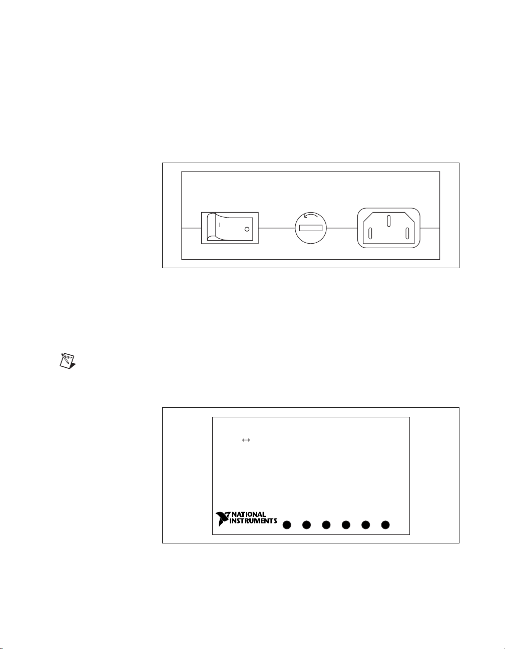
AC Version Front Panel
The power switch, fuse holder, and power cord receptacle are located on
the GPIB-232/485CT-A front panel, on the AC version only. Figure 1-1
shows the front panel of the AC version.
Chapter 1 Hardware Overview
FUSE
Top Panel
Note
similar.
Figure 1-1.
The AC Version Front Panel
The six light-emitting diodes (LEDs) are located on the
GPIB-232/485CT-A top panel. Figure 1-2 shows the top panel.
The following figures show only the GPIB-232CT-A, but the GPIB-485CT-A is
GPIB-232CT-A
RS-232 IEEE 488 Controller
POWER
Figure 1-2.
TALK
READY
The Top Panel
LISTEN
SRQ
ATN
© National Instruments Corporation 1-3 GPIB-232/485CT-A User Manual
Page 18
Chapter 1 Hardware Overview
The LEDs show the current status of the GPIB-232/485CT-A at all times.
Table 1-1 describes each LED.
Rear Panel
Table 1-1.
LED Descriptions
LED Indication
POWER In dicates that power to the unit has been applied and
the ON/OFF switch is in the ON position.
READY Indicates that the power-on self-test has passed
successfully and the unit is ready to operate.
TALK Indicates that the GPIB-232/485CT-A is addressed as
a GPIB Talker.
LISTEN Indicates that the GPIB-232/485CT-A is addressed as
a GPIB Listener.
SRQ Indicates that the GPIB signal line SRQ* is asserted.
ATN Indicates that the GPIB signal line ATN* is asserted.
* indicates that the signal is active low (negative logic or low when asserted).
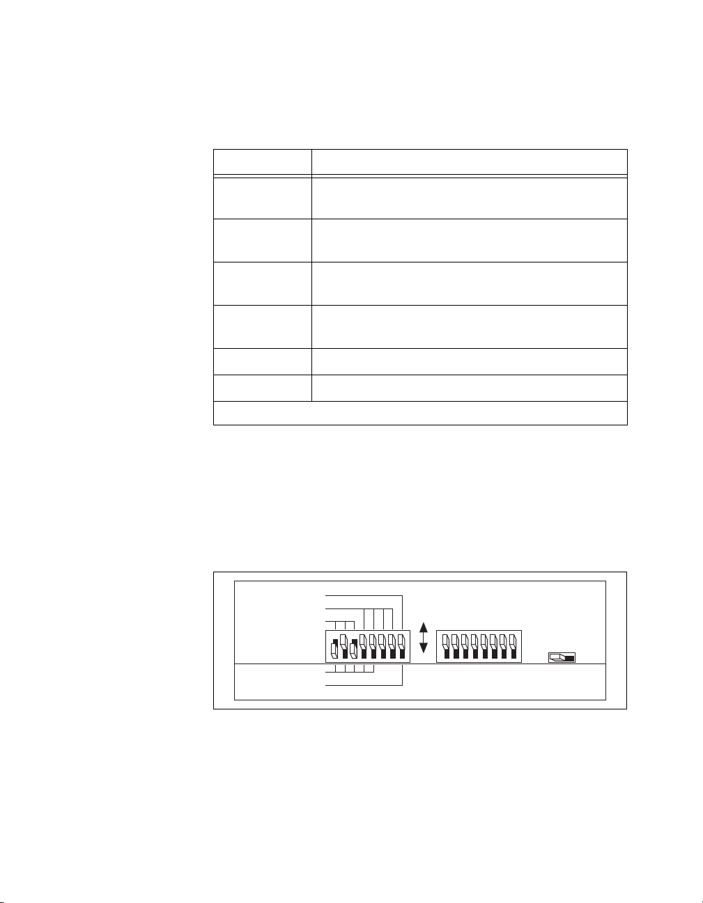
The configuration switches are located on the rear panel of the
GPIB-232/485CT-A. Figure 1-3 shows the rear panel of the AC version.
Figure 1-4 shows the rear panel of the DC version. The unmarked DIP
switches are reserved for future development and should remain in the
OFF position.
S MODE
DATA FORMAT
BAUD RATE
GPIB ADDRESS
G MODE
Figure 1-3.
GPIB-232/485CT-A User Manual 1-4 www.ni.com
OFF
ON
The DC Version Rear Panel
ON OFF
Page 19
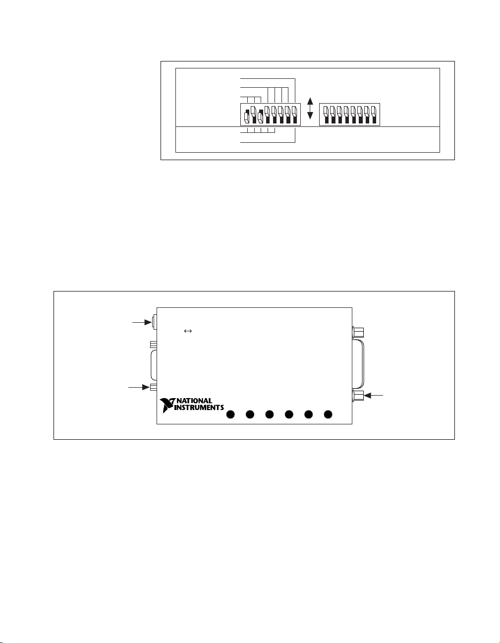
Side Panels
Chapter 1 Hardware Overview
S MODE
DATA FORMAT
BAUD RATE
GPIB ADDRESS
G MODE
OFF
ON
Figure 1-4. The AC Version Rear Panel
The GPIB connector and the serial connector are mounted on opposite side
panels. On the DC version, the DC power jack is located next to the serial
connector.
Figure 1-5 shows the location of the serial and GPIB connectors and the
DC power jack.
DC Power Jack
(DC version only)
Serial Connector
GPIB-232CT-A
IEEE 488 ControllerRS-232
READY
TALK
POWER
Figure 1-5. Location of the Connectors and the DC Power Jack
LISTEN
SRQ
GPIB Connector
ATN
© National Instruments Corporation 1-5 GPIB-232/485CT-A User Manual
Page 20

Chapter 1 Hardware Overview
RS-232 Connector
The RS-232 port on the GPIB-232CT-A is configured as a DTE (Data
Terminal Equipment) and uses a standard 9-pin shielded D-Subminiature
male connector with screwlock assemblies. The RS-232 connector accepts
standard 9-pin D-Subminiature female connectors. Figure 1-6 shows a
diagram of the RS-232 connector and the signals supported. For more
information on the RS-232 signals refer to Appendix D, Interfacing to an
RS-232 Device.
No Connection
No Connection
Figure 1-6.
6789
RTS
CTS
No Connection
23451
RXD
TXD
DTR
GND
The RS-232 Connector and Signal Designations
GPIB-232/485CT-A User Manual 1-6 www.ni.com
Page 21

Chapter 1 Hardware Overview
RS-485 Connector
The RS-485 port on the GPIB-485CT-A uses a standard 9-pin shielded
D-Subminiature male connector with screwlock assemblies. The RS-485
connector accepts standard 9-pin D-Subminiature female connectors.
Figure 1-7 shows a diagram of the serial connector and the signals
supported. For more information on the RS-485 signals refer to
Appendix E, Interfacing to an RS-485 Device.
CTS - (HSI –)
RTS - (HSO –)
Figure 1-7.
6789
TXD +
TXD –
GND
23451
CTS+(HSI+)
RTS+(HSO+)
RXD+
RXD–
The RS-485 Connector and Signal Designations
© National Instruments Corporation 1-7 GPIB-232/485CT-A User Manual
Page 22

Chapter 1 Hardware Overview
GPIB Connector
The GPIB connector is a standard 24-pin shielded Champ female connector
with metric screwlock hardware. Figure 1-8 shows a diagram of the GPIB
connector and the signals supported. A * suffix indicates that the signal is
active low. Refer to Appendix F, GPIB Basics, for more information about
the GPIB signal lines.
13
DIO1*
DIO2*
DIO3*
DIO4*
EOI*
DAV*
NRFD*
NDAC*
IFC*
SRQ*
ATN*
SHIELD
1
2
3
4
5
6
7
8
9
10
11
12
DIO5*
14
DIO6*
15
DIO7*
16
DIO8*
17
REN*
18
GND (Twisted Pair with DAV*)
19
GND (Twisted Pair with NRFD*)
20
GND (Twisted Pair with NDAC*)
GND (Twisted Pair with IFC*)
21
GND (Twisted Pair with SRQ*)
22
GND (Twisted Pair with ATN*)
23
SIGNAL GROUND
24
Figure 1-8.
GPIB-232/485CT-A User Manual 1-8 www.ni.com
The GPIB Connector and Signal Designations
Page 23

Operating in S Mode and
G Mode
This chapter helps you determine which mode of operation, S mode or
G mode, you should use. It also describes data buffering and handshaking
schemes.
Choosing Between S Mode and G Mode
The GPIB-232/485CT-A can be connected to a serial device and one or
more GPIB devices. The way you use the serial device in your system setup
determines which mode of operation you should use. If the serial device is
the Controller, you should use S mode. If the serial device is a
Talker/Listener only, and a GPIB device is the Controller, you should use
G mode.
Operating in S Mode
The GPIB-232/485CT-A should be configured to operate in S mode if your
serial device acts as a Controller in the GPIB system, addressing devices,
and performing other GPIB Controller functions. In S mode operation, you
can use the NI-488.2 software.
2
© National Instruments Corporation 2-1 GPIB-232/485CT-A User Manual
Page 24
Chapter 2 Operating in S Mode and G Mode
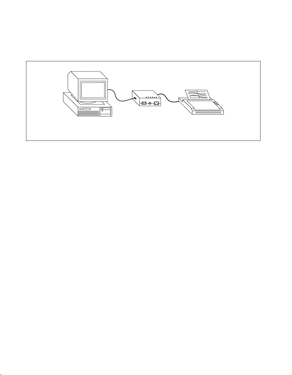
Figure 2-1 shows an example of a setup using S mode. The
GPIB-232/485CT-A is connected to a PC, which is controlling a GPIB
plotter.
IBM PC
(Controller)
Refer to Chapter 3, Installing and Configuring Your Controller, for
detailed information on setting up your GPIB-232/485CT-A to operate in
S mode. Refer to Chapter 4, Programming in S Mode, and Chapter 5,
S Mode Functions, for information on programming the
GPIB-232/485CT-A in S mode.
Operating in G Mode
The GPIB-232/485CT-A should be configured to operate in G mode if your
serial device acts only as a Talker and/or Listener while a GPIB device
manages the system, sending and receiving data to and from the serial
device.
Serial Cable
GPIB-232CT-A
GPIB Cable
READY
TALK
POWER
LISTEN
BUSY
FULL
GPIB-232/485CT-A
Figure 2-1. Example of S Mode System Setup
Plotter
(GPIB Device)
GPIB-232/485CT-A User Manual 2-2 www.ni.com
Page 25
Chapter 2 Operating in S Mode and G Mode
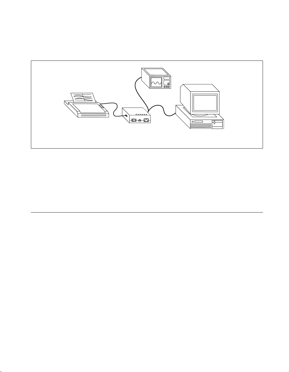
Figure 2-2 shows an example of a setup using G mode. The
GPIB-232/485CT-A is connected to a serial printer, which is programmed
by the GPIB Controller.
GPIB Device
Serial Cable GPIB Cables
GPIB-232CT-A
POWER
READY
TALK
LISTEN
FULL
BUSY
Serial Device
(Talker/Listener)
GPIB-232/485CT-A
IBM PC with GPIB Board
(Controller)
Figure 2-2. Example of G Mode System Setup
Refer to Chapter 3, Installing and Configuring Your Controller, for
detailed information on setting up your GPIB-232/485CT-A to operate in
G mode. Refer to Chapter 6, Programming in G Mode, and Chapter 7,
G Mode Functions, for information on programming in G mode.
Data Buffering and Handshaking Schemes
Two protection mechanisms are used to ensure that the
GPIB-232/485CT-A does not lose incoming serial data: data buffering and
handshaking.
The GPIB-232/485CT-A has an internal RAM buffer that stores incoming
serial data until it can output the data to the GPIB port. The size of this
RAM buffer determines ho w much serial data the GPIB-232/485CT-A can
accept before the buffer is completely full.
When its RAM buffer is nearly full, the GPIB-232/485CT -A can handshake
with the serial host to stop data transmission. When the buffer is almost
empty , the GPIB-232/485CT-A can again handshake with the serial host to
start data transmission. The GPIB-232/485CT-A is capable of using both
the XON/XOFF software handshaking and the hardware handshaking
protocols.
© National Instruments Corporation 2-3 GPIB-232/485CT-A User Manual
Page 26

Chapter 2 Operating in S Mode and G Mode
Hardware Handshaking
The hardware handshake function is always active during serial data
transfers and uses the Request to Send (RTS on the GPIB-232CT-A,
RTS+ and RTS– on the GPIB-485CT-A) and Clear to Send (CTS on the
GPIB-232CT-A, CTS+ and CTS– on the GPIB-485CT-A) signal lines.
When the GPIB-232/485CT-A is ready to accept serial data, it asserts the
RTS line(s). RTS remains asserted until the GPIB-232/485CT-A data
buffer is almost full. At this point, the GPIB-232/485CT-A unasserts the
RTS line(s), signaling to the serial host that it is no longer ready to accept
data. The serial host should monitor the RTS line(s) and suspend data
transmission whenever RTS becomes unasserted. The GPIB-232/485CT-A
asserts RTS when it is again ready to receive serial data.
The GPIB-232/485CT-A is also able to suspend transmission when the
serial device is no longer ready to accept data. The GPIB-232/485CT-A is
configured to immediately stop transmission of serial data when CTS
becomes unasserted. It resumes transmission when CTS is reasserted.
Because most serial devices use the same form of hardware handshaking as
the GPIB-232/485CT-A, you can achieve bidirectional flow control by
using a serial cable that connects the GPIB-232/485CT -A RTS signal(s) to
the serial device CTS signal(s). In addition, the serial device RTS signal(s)
should be connected to the GPIB-232/485CT-A CTS signal(s). This setup
allows each device to monitor the RTS signal(s) of the other device and to
suspend transmission when necessary to prevent data loss. Refer to or
Appendix D, Interfacing to an RS-232 Device, or Appendix E, Interfacing
to an RS-485 Device, for more information on wiring schemes.
XON/XOFF Software Handshaking
If your serial device does not implement or recognize the hardware
handshake scheme, your cable does not support the necessary handshake
lines, or your application software requires XON/XOFF handshaking, you
might need to enable the XON/XOFF handshaking protocol by using the
xon command. This handshaking protocol performs the same function as
the hardware handshake but does so by sending special control codes over
the data lines instead of changing logic levels on dedicated control lines.
When you enable the XON/XOFF protocol, the GPIB-232/485CT -A sends
the XOFF character (decimal 19 or <CTRL-S>) before the internal buffer
overflows. When the GPIB-232/485CT-A is able to start receiving
characters again, it sends the XON character (decimal 17 or <CTRL-Q>).
Similarly, if the GPIB-232/485CT-A is transmitting data and receives the
GPIB-232/485CT-A User Manual 2-4 www.ni.com
Page 27

Chapter 2 Operating in S Mode and G Mode
XOFF character, it suspends transmission of any further data until it
receives the XON character.
If you are transmitting binary data (as opposed to 7-bit ASCII), do not
configure the GPIB-232/485CT-A to use XON/XOFF software
handshaking. Because the binary data could contain any binary sequence,
including decimal 19 (<Ctrl-S>) or decimal 17 (<Ctrl-Q>), the
GPIB-232/485CT-A would not be able to distinguish between data values
or handshake control codes. If XON/XOFF software handshaking were
enabled in this case, the GPIB-232/485CT-A would handshake erratically.
© National Instruments Corporation 2-5 GPIB-232/485CT-A User Manual
Page 28

Installing and Configuring
Your Controller
This chapter contains detailed instructions for connecting and configuring
your GPIB-232/485CT-A.
Check the Hardware Configuration
The AC versions of the GPIB-232/485CT-A are shipped with a 100–120 V
or 220–240 V internal power supply. The DC versions of the
GPIB-232/485CT-A are shipped with a 100–120 V or 220–240 V,
wall-mount or desktop power supply. Before configuring your
GPIB-232/485CT-A, verify that the voltage marked on the
GPIB-232/485CT-A or on the power supply matches the voltage that is
supplied in your area.
3
Caution
marked on your GPIB-232/485CT-A. Doing so could damage the unit. Replacement fuses
for the AC version must be the proper type and size. For fuse specifications, refer to
Appendix A, Specifications.
© National Instruments Corporation 3-1 GPIB-232/485CT-A User Manual
Do not operate your GPIB-232/485CT-A at any voltage other than the one
The GPIB-232/485CT-A is shipped with the following default settings:
• S mode
• 7 data bits/character
• 1 stop bit/character
• Parity disabled
• Serial port configured to 9600 baud
If you want to change any of the default settings, you must change the DIP
switch settings. To change the settings, shut down your system and then
refer to the section Configure the Hardware later in this chapter. If you plan
to use the default settings, continue with the next section.
Page 29

Chapter 3 Installing and Configuring Your Controller
Connect the Hardware
Complete the following steps to connect the GPIB-232/485CT-A to your
system.
Step 1. Power Off Your System
Power off your system, turn off your computer, and unplug the power cord.
Step 2. Verify That You Have a Null-Modem Serial Cable
You must use a null-modem serial cable (also known as a file transfer cable
or a DTE-to-DTE cable) to connect your computer to the GPIB-232CT-A.
The following National Instruments cables are null-modem serial cables.
National Instruments
See Appendix D, Interfacing to an RS-232 Device, and Appendix E,
Interfacing to an RS-485 Device, for more information on cable pinouts.
Step 3. Connect the Cables
1. Connect the serial cable to the GPIB-232/485CT-A serial connector
and securely fasten the holding screws. Connect the other end of the
cable to your serial device. Be sure to use only shielded serial cables,
and follow the appropriate serial cabling restrictions.
2. Connect the GPIB cable to the GPIB connector on the
GPIB-232/485CT-A, and tighten the thumb screws on the connector.
Connect the other end to your GPIB device(s). Be sure to use only
shielded GPIB cables, and follow all IEEE 488 cabling restrictions.
3. If you have an AC version, connect the power cord to the power
receptacle on the front panel of the GPIB-232/485CT-A, then plug the
supply into an AC outlet of the correct voltage.
Table 3-1.
Part Number
182238-01 9-pin to 9-pin, 1 m
182238-02 9-pin to 9-pin, 2 m
182238-04 9-pin to 9-pin, 4 m
181074-10 9-pin to 25-pin, 1 m
National Instruments Null-Modem Serial Cables
Cable Type
GPIB-232/485CT-A User Manual 3-2 www.ni.com
Page 30

Chapter 3 Installing and Configuring Your Controller
If you have a DC version, connect the DC power plug of the DC power
supply to the power jack on the serial end of the GPIB-232/485CT-A,
then plug the supply into an AC outlet of the correct voltage.
Step 4. Power On Your System and the GPIB-232/485CT-A
1. Plug in the power cords for your computer system and power on all
devices.
2. If you have an AC v ersion, use the front panel rocker switch to power
on your GPIB-232/485CT -A. If you ha v e a DC version, use the po wer
switch on the rear panel to power on your GPIB-232/485CT-A.
The POWER LED indicator should come on immediately. The
READY LED indicator should come on after the GPIB-232/485CT- A
has passed its power-on self test, indicating the unit is ready for
operation. If the READY LED does not come on within seven seconds
after the unit is powered on, recheck all connections and switch
settings and retry the power-on sequence. If the READY LED still
does not come on, contact National Instruments.
Configure the Hardware
If you want to change the settings of the GPIB-232/485CT-A, power off
your system and follow the instructions in the next sections.
Changing the S Mode Characteristics
You can use the DIP switch on the rear panel to configure the serial port
characteristics of the GPIB-232/485CT-A in S mode. When switch 8 is set
to S mode, switches 1 through 3 set the baud rate, and switches 4 through
7 set the data formatting characteristics. Figure 3-1 shows the DIP switch.
The unmarked DIP switches on the rear panel are reserved for future
development and should remain in the OFF position.
© National Instruments Corporation 3-3 GPIB-232/485CT-A User Manual
Page 31

Chapter 3 Installing and Configuring Your Controller
Note The numbers 1–8 do not appear on the box. They are included in these illustrations
as a reference aid.
S MODE
DATA FORMAT
BAUD RATE
OFF
1 2 3 4 5 6 7 8
GPIB ADDRESS
G MODE
Figure 3-1. Default Setting (S Mode) for DIP Switch
ON
In Figure 3-1, switch 8 is set to S mode, so the labels on top of the switch
apply . Switches 1 through 3 are ON, OFF, and ON, respectively , indicating
that the serial port is operating at 9600 baud. Switches 4 and 5 are both
OFF, which indicates that parity is disabled. Switch 6 is OFF,
indicating 1 stop bit/character. Switch 7 is OFF, indicating that the
GPIB-232/485CT-A is using 7 bits per character for serial data transfers.
Tables 3-2 and 3-3 show the possible configurations for the baud rate and
data format switches when you are using S mode and what each
configuration indicates. Default settings are in bold.
Table 3-2. S Mode Switch Settings for Serial Port Baud Rate
Switches
Indication1 2 3
OFF OFF OFF 300 baud
ON OFF OFF 600 baud
OFF ON OFF 1200 baud
ON ON OFF 2400 baud
OFF OFF ON 4800 baud
ON OFF ON 9600 baud
OFF ON ON 19200 baud
ON ON ON 38400 baud
GPIB-232/485CT-A User Manual 3-4 www.ni.com
Page 32

Chapter 3 Installing and Configuring Your Controller
Table 3-3.
Switch Position Indication
4 OFF odd parity
5 OFF parity generation/checking disabled
6 OFF 1 stop bit/character
7 OFF 7 bits/character
8 OFF operates in S mode
S Mode Switch Settings for Data Formatting Characteristics
ON even parity
ON parity generation/checking enabled
ON 2 stop bits/character
ON 8 bits/character
ON operates in G mode
Sample Switch Settings for S Mode
To operate in S mode, set switch 8 to OFF. Set the remaining switches to
match the characteristics of the terminal or computer you attach to the other
end of the serial cable.
Often, you can change the serial port characteristics of the terminal or
computer by setting switches or running a utility program, or from within
a programming environment. Determine the default characteristics of your
computer or terminal’s serial port. If you want to change the conf iguration
on that side, do so before attempting to communicate with the
GPIB-232/485CT-A. Then set the configuration switch on the
GPIB-232/485CT-A to match your serial port characteristics.
IBM PC or Compatibles
If your computer is an IBM PC or compatible, the serial port default
characteristics on the PC are as follows:
Baud rate 1200
Parity Even
Data bits 7
Stop bits 1
© National Instruments Corporation 3-5 GPIB-232/485CT-A User Manual
Page 33

Chapter 3 Installing and Configuring Your Controller
If these defaults meet the needs of your application, set the
GPIB-232/485CT-A switches as shown in Figure 3-2.
S MODE
DATA FORMAT
BAUD RATE
OFF
1 2 3 4 5 6 7 8
GPIB ADDRESS
G MODE
Figure 3-2. Switch Settings to Match IBM PC Defaults
ON
In many cases, you might want to change the default characteristics of the
serial port on the IBM PC. You might want to run at a higher baud rate and
you might want to send 8-bit data bytes for binary data that are sent to the
GPIB device. To change the IBM PC’s serial port characteristics to
9600 baud and 8 data bits from within Quick BASIC, place the following
statement at the beginning of your application program:
OPEN "COM1:9600,,8," AS #1
Then set the switches on the GPIB-232/485CT-A as shown in Figure 3-3.
S MODE
DATA FORMAT
BAUD RATE
1 2 3 4 5 6 7 8
GPIB ADDRESS
G MODE
OFF
ON
Figure 3-3. Sample Switch Settings with an IBM PC or Compatible
Other Systems
If your computer (or terminal) is other than those described in this chapter,
refer to the manual that came with your equipment to learn the default
settings of the serial port and how to change them.
Whatever serial port characteristics you decide to use, you must set up both
your serial device and your GPIB-232/485CT -A to identical characteristics.
GPIB-232/485CT-A User Manual 3-6 www.ni.com
Page 34

Changing the G Mode Characteristics
You can use the DIP switch on the rear panel to configure the G mode
settings. When switch 8 is set to G mode, switches 1 through 5 set the GPIB
addresses for the GPIB-232/485CT-A and the serial device connected to it.
Figure 3-4 shows a sample G mode setting. The unmarked DIP switches on
the rear panel are reserved for future development and should remain in the
OFF position.
DATA FORMAT
BAUD RATE
Chapter 3 Installing and Configuring Your Controller
S MODE
OFF
GPIB ADDRESS
Figure 3-4.
In Figure 3-4, switches 1 through 5 are ON, OFF, ON, OFF, and OFF,
respectively, indicating that the GPIB-232/485CT-A is at GPIB address 5
and the serial device is at GPIB address 6. Switches 6, 7, and 8 are OFF,
OFF, and ON, respectively, indicating that the GPIB-232/485CT-A is
operating in G mode. Switches 6 and 7 must remain in the OFF position
while in G mode.
Choosing GPIB Addresses for G Mode
When you use the GPIB-232/485CT-A in G mode, switches 1 through 5 set
the primary GPIB address of the GPIB-232/485CT-A. The primary address
plus one is the GPIB address of the serial device connected to the
GPIB-232/485CT-A. Before you set the address switches, find two
consecutive addresses that are not used by any other GPIB devices in your
system. Refer to Addressing the GPIB-232/485CT-A and Serial Device in
Chapter 6, Programming in G Mode, for more information. Table 3-4
1 2 3 4 5 6 7 8
G MODE
Sample G Mode Switch Setting
ON
© National Instruments Corporation 3-7 GPIB-232/485CT-A User Manual
Page 35

Chapter 3 Installing and Configuring Your Controller
shows the switch settings for the first (primary) GPIB address and the
corresponding serial device address.
Table 3-4. GPIB Address Switch Settings for G Mode
Switches GPIB-232/
1 2 3 4 5
485CT-A
Address
Serial
Device
Address
OFF OFF OFF OFF OFF 0 1
ON OFF OFF OFF OFF 1 2
OFF ON OFF OFF OFF 2 3
ON ON OFF OFF OFF 3 4
OFF OFF ON OFF OFF 4 5
ON OFF ON OFF OFF 5 6
OFF ON ON OFF OFF 6 7
ON ON ON OFF OFF 7 8
OFF OFF OFF ON OFF 8 9
ON OFF OFF ON OFF 9 10
OFF ON OFF ON OFF 10 11
ON ON OFF ON OFF 11 12
OFF OFF ON ON OFF 12 13
ON OFF ON ON OFF 13 14
OFF ON ON ON OFF 14 15
ON ON ON ON OFF 15 16
OFF OFF OFF OFF ON 16 17
ON OFF OFF OFF ON 17 18
OFF ON OFF OFF ON 18 19
ON ON OFF OFF ON 19 20
OFF OFF ON OFF ON 20 21
ON OFF ON OFF ON 21 22
OFF ON ON OFF ON 22 23
GPIB-232/485CT-A User Manual 3-8 www.ni.com
Page 36

Chapter 3 Installing and Configuring Your Controller
Table 3-4. GPIB Address Switch Settings for G Mode (Continued)
Switches GPIB-232/
1 2 3 4 5
485CT-A
Address
Serial
Device
Address
ON ON ON OFF ON 23 24
OFF OFF OFF ON ON 24 25
ON OFF OFF ON ON 25 26
OFF ON OFF ON ON 26 27
ON ON OFF ON ON 27 28
OFF OFF ON ON ON 28 29
ON OFF ON ON ON 29 30
OFF ON ON ON ON 30 0
© National Instruments Corporation 3-9 GPIB-232/485CT-A User Manual
Page 37

Programming in S Mode
This chapter describes how to program the GPIB-232/485CT-A in S mode.
It explains status information and error handling, programming
considerations, programming messages, function arguments, GPIB
termination methods, function names, S mode default settings, and the
S mode functions.
Choosing Your S Mode Programming Method
When using the GPIB-232/485CT-A in S mode, you can either use the
S mode functions listed in the manual, or you can use the high-level
NI-488.2 software for the GPIB-232/485CT-A. If you want to use the
functions listed in this manual, refer to this chapter and Chapter 5, S Mode
Functions, for programming information. If you want to use the NI-488.2
software, refer to the NI-488.2 user manual and NI-488.2 function
reference manual. Contact National Instruments for ordering information
if you do not have the NI-488.2 software package.
4
Status Information and Error Handling Characteristics
The function descriptions in Chapter 5, S Mode Functions, explain that the
GPIB-232/485CT-A records specific status and error information. This
means that it stores that information in its memory so that it is available
when you request it.
The function descriptions also explain that the GPIB-232/485CT -A returns
certain information to you. This means that the GPIB-232/485CT- A sends
information to you over the serial port.
The GPIB-232/485CT-A continuously monitors the serial port for
transmission errors. If it encounters an error in the serial data,
the GPIB-232/485CT-A records the error. You can program the
GPIB-232/485CT-A to ignore serial port errors using the
© National Instruments Corporation 4-1 GPIB-232/485CT-A User Manual
spign function.
Page 38

Chapter 4 Programming in S Mode
Programming Considerations
• The programming examples for each function description are in
Microsoft QuickBASIC Version 4.5. Although the examples in this
manual are written in BASIC, you can program the
GPIB-232/485CT-A using any programming language that has access
to a serial port.
• In the function syntax descriptions, arguments enclosed in square
brackets (
argument.
• For all programming examples, the communications port has been
assigned to file number 1 (
statement.
• The I/O and high-level bus management functions are the most
frequently used and should meet most of your needs. In the
descriptions that follow, these functions are marked with an asterisk
(*).
• You can use function name abbreviations, which include only as many
characters as necessary to distinguish them from other functions. The
abbreviated forms are indicated by bold text in the syntax description
of each function.
[]) are optional. Do not enter the brackets as part of your
#1) by the BASIC OPEN "COM..."
Programming Messages
You can program the GPIB-232/485CT-A by sending programming
messages (ASCII strings) and data strings to its serial port.
Programming Message Format
Each programming message is terminated with a carriage return (<CR>), a
linefeed (<LF>), or a carriage return followed by a linefeed (<CR><LF>).
Message termination is indicated by a <CR> in the syntax portions of the
function descriptions. In the programming examples, the BASIC
statement automatically sends a carriage return at the end of the string,
so a carriage return is not needed as part of the code.
You can enter programming messages in any combination of uppercase and
lowercase letters.
GPIB-232/485CT-A User Manual 4-2 www.ni.com
PRINT #
Page 39

Programming Message Example 1
The following line of code is an example programming message in BASIC.
PRINT #1,"clr 3,4"
This programming message contains the function name clr and the
arguments
3 and 4. It tells the GPIB-232/485CT-A to clear the devices at
GPIB addresses 3 and 4.
characters to the serial port after the serial port has been opened with the
"OPEN COM..." statement. In this example, BASIC automatically sends a
<CR>, so it is not necessary to include it in the code.
Programming Message Example 2
To send more than one programming message with one PRINT statement,
you can embed a <CR> (denoted by
CHR$(10)) in the statement. For example, to send the two programming
messages "send interface clear" (
you could use either of these two sequences:
PRINT #1,"sic"
PRINT #1,"sre 1"
or
PRINT #1,"sic"+CHR$(13)+"sre 1"
Chapter 4 Programming in S Mode
PRINT #1 is the BASIC command to send
CHR$(13)) or a <LF> (denoted by
sic) and "send remote enable" (sre),
Programming Message Example with Data String
The following line of BASIC code is an example of a programming
message with a data string.
PRINT #1, "wrt 2"
PRINT #1, "IN;CI;"
This programming message contains the function name wrt, the argument
2, and the data string
the device at primary address 2.
the data
wrt sends out on the GPIB. In this case, a <CR> is automatically
sent by BASIC follo wing each print string, so it is not necessary to include
it in the code.
Both the
cmd and wrt programming messages are followed by a data string
that can contain 7- or 8-bit data.
© National Instruments Corporation 4-3 GPIB-232/485CT-A User Manual
"IN;CI;". It tells the GPIB-232/485CT -A to write to
"IN;CI;" is the data string that contains
Page 40

Chapter 4 Programming in S Mode
How Messages are Processed
The GPIB-232/485CT-A processes a programming message on a
line-by-line basis. When the GPIB-232/485CT-A receives a message,
it buffers the entire message, interprets the function name and arguments,
then executes the message. The data portions of the
are processed differently. The data immediately following a
function are sent directly to the GPIB.
The GPIB-232/485CT-A recognizes <CTRL-H> (hex 8) in a programming
message as a backspace and erases the previous character. The
GPIB-232/485CT-A recognizes <CTRL-H> in a data string as a data byte
and does not erase the previous character.
Function Arguments
When specifying a function, separate the first argument from the function
name with at least one space. Separate each additional argument with at
least one space or a comma.
In the syntax portions of the function descriptions in Chapter 5, S Mode
Functions, the information within the square brackets (
If you want to include optional information, do not include the brackets as
part of your argument.
wrt and cmd functions
wrt and a cmd
[]) is optional.
Abbreviations for Arguments
The function descriptions in Chapter 5, S Mode Functions, use
abbreviations for some arguments. The abbreviations are as follows:
addr a GPIB address
alist one or more addrs
bool a boolean value (1 = true, on, or enable or 0 = false, off, or
disable)
GPIB Address
One argument used with most functions is the GPIB address. Each device
on the GPIB has a GPIB address. The GPIB-232/485CT-A address is 0 at
power on, but you can change it using the
manuals that came with your GPIB devices to learn their addresses. You
should know the addresses when you program the GPIB-232/485CT-A.
Only the lower fi ve bits of each GPIB address are significant. These bits can
range from 0 through 30 for both the primary and the secondary address.
GPIB-232/485CT-A User Manual 4-4 www.ni.com
caddr function. Refer to the
Page 41

For example, the binary value 01100010 (decimal 98) is interpreted as
decimal 2.
Each of the following GPIB addresses specifies a primary address of 0 and
a secondary address of 2. A plus sign (+) separates the primary address
from the secondary address.
0+2 or 0+98 or 32+98 or 0+\x62
Lists of GPIB Addresses
When a function requires a list of one or more GPIB addresses, the
maximum number of addresses that you can specify is 14. If you specify
more than 14 addresses, the GPIB-232/485CT-A records the EARG error.
This limit exists because the IEEE 488 specification allows no more than
15 GPIB devices to coexist on any GPIB.
Numeric String Arguments
Another type of argument is a numeric string. A numeric string represents
an integer which you can express using decimal, octal, or hexadecimal
digits. To specify an octal integer, precede the numeric string with a
backslash (
with a backslash X (
Chapter 4 Programming in S Mode
\). To specify a hexadecimal integer, precede the numeric string
\X).
Each of the following numeric strings represents the decimal value 112:
decimal octal hexadecimal
112 \160 \x70
GPIB Read and Write Termination Methods
(END and EOS)
The IEEE 488 specification defines two ways that GPIB Talkers and
Listeners can identify the last byte of data messages: END and EOS. The
two methods permit a Talker to send data messages of any length without
the Listener(s) knowing the number of transmission bytes in advance. END
and EOS can be used individually or in combination, but the Listener must
be configured to detect the end of a transmission.
END message The Talker asserts the EOI* (End Or Identify)
signal while the last data byte is being transmitted.
The Listener stops reading when it detects a data
© National Instruments Corporation 4-5 GPIB-232/485CT-A User Manual
Page 42

Chapter 4 Programming in S Mode
EOS character The Talker sends an EOS (e nd-of-string) character
byte accompanied by EOI*, regardless of the v alue
of the byte.
at the end of its data string. The Listener stops
receiving data when it detects the EOS character.
Either a 7-bit ASCII character or a full 8-bit binary
byte can be used.
The GPIB-232/485CT-A always terminates GPIB
END message. Y ou can use the
and write termination methods.
eos and eot functions to change GPIB read
rd operations on the
Function Names
Each function name has been selected to indicate the function’s purpose
and make your programs easier to understand. However, if you want to
reduce some overhead in your program, you can use an abbreviation of the
name that includes only as much of the function name as is necessary to
distinguish it from other functions. This abbreviated form of the function
name is shown in bold text in the function tables and in the syntax portions
of the function descriptions.
S Mode Default Settings and Related Functions
Tables 4-1 and 4-2 list power-on characteristics of the GPIB-232/485CT-A
in S mode and the functions you can use to change those characteristics.
Table 4-1.
Characteristic Default Setting Related Function
Echo bytes to serial port no
S Mode Serial Port Characteristics
echo
Ignore serial port errors yes
Send XON/XOFF no
Recognize XON/XOFF no
GPIB-232/485CT-A User Manual 4-6 www.ni.com
spign
xon
xon
Page 43

Chapter 4 Programming in S Mode
Table 4-2.
GPIB Characteristics in S Mode
Characteristic Default Setting Related Function
Primary/secondary address pad = 0,
IEEE 488 parallel
poll subset
End-of-string modes none
Send END on writes yes
IST bit setting 0
GPIB-232/485CT-A is
System Controller
I/O timeout 10 s
Serial poll timeout 0.1 s
List of S Mode Functions by Group
The GPIB-232/485CT-A S mode functions are divided into three main
groups: GPIB functions, serial port functions, and general use functions.
For more information about the S mode functions, refer to the alphabetical
list of functions at the end of this chapter, or to Chapter 5, S Mode
Functions.
sad = none
PP1 (remote)
yes
caddr
conf
eos
eot
ist
rsc
tmo
tmo
GPIB Functions
The GPIB functions manage the GPIB port of the GPIB-232/485CT-A.
The GPIB function subgroups are listed with the most frequently used
groups first. Often, the I/O and high-level bus management functions are
the only ones you need.
I/O Functions—read data from and write to GPIB devices.
•
rd
•
wrt
© National Instruments Corporation 4-7 GPIB-232/485CT-A User Manual
Page 44

Chapter 4 Programming in S Mode
High-Level Bus Management Functions—send frequently used bus
management instructions to GPIB devices.
• clr
• loc
• trg
GPIB Initialization Functions—initialize various configurations of the
GPIB port.
•
• eos
•
• onl
•
• tmo
Serial Poll Functions—conduct and respond to GPIB serial polls.
• rsp
• rsv
caddr
eot
rsc
Low-Level Bus Management Functions—give you precise control over
the GPIB. Use them when the I/O and high-level bus management
functions do not meet the needs of your GPIB device.
•
cac
• cmd
• gts
• lines
• ln
• pct
• sic
• sre
Parallel Poll Functions—conduct and respond to GPIB parallel polls.
•
ist
• ppc
• ppu
• rpp
GPIB-232/485CT-A User Manual 4-8 www.ni.com
Page 45

Serial Port Functions
The serial port functions initialize and manage the serial port of the
GPIB-232/485CT-A.
•
echo
•
spign
•
xon
General Use Functions
The general use functions are used for general operations that are not
provided by the GPIB functions or serial port functions.
•
conf
• id
• stat
• wait
Alphabetical List of S Mode Functions
Table 4-3 lists all of the S mode functions in alphabetical order.
Chapter 4 Programming in S Mode
Table 4-3.
Alphabetical List of S Mode Functions
Function Purpose
cac mode Become Active Controller
caddr address Change the GPIB address of the
GPIB-232/485CT-A
clr address list Clear specified device(s)
cmd count commands Send GPIB commands
conf option value Read/change configuration
echo on/off Echo characters received from serial port
eos modes, eoschar Change or disable GPIB end-of-string
termination mode
eot on/off Enable or disable END termination message
on GPIB write operations
gts mode Go from Active Controller to Standby
© National Instruments Corporation 4-9 GPIB-232/485CT-A User Manual
Page 46

Chapter 4 Programming in S Mode
Table 4-3. Alphabetical List of S Mode Functions (Continued)
Function Purpose
id
ist set/clear Set or clear individual status bit for use in
Identify system
GPIB-232/485CT-A response to parallel
polls
lines
ln address list Check for listening devices
loc address list Go to Local
onl on/off Place the GPIB-232/485CT-A online/offline
pct address Pass Control
ppc values Parallel Poll Configure
ppu address list Parallel Poll Unconfigure
rd count, address Read data
rpp
rsc on/off Request System Control
rsp address list Conduct (request) a serial poll
rsv status byte Request service and/or set or change the
Determine state of GPIB control lines
Conduct (request) a Parallel Poll
serial poll status byte
sic time Send Interface Clear
spign on/off Ignore serial port errors
sre on/off Set remote enable
stat modes Return GPIB-232/485CT -A status
tmo values Change or disable time limits
trg address list Trigger selected device(s)
wait mask Wait for selected event(s)
wrt count, address list,
Write data
data
xon modes Change serial port XON/XOFF protocol
GPIB-232/485CT-A User Manual 4-10 www.ni.com
Page 47

Chapter 4 Programming in S Mode
For more detailed information on each function, refer to Chapter 5, SMode
Functions.
© National Instruments Corporation 4-11 GPIB-232/485CT-A User Manual
Page 48

S Mode Functions
This chapter contains descriptions of the S mode functions you can use to program the
GPIB-232/485CT-A. These functions are in alphabetical order for easy reference.
The I/O and high-level bus management functions are the most frequently used and should
meet most of your needs. In the descriptions that follow, these functions are marked with an
asterisk (*).
For general information about using S mode functions, refer to Chapter 4, Programming in
S Mode.
5
© National Instruments Corporation 5-1 GPIB-232/485CT-A User Manual
Page 49

Chapter 5 S Mode Functions — cac
cac
Become Active Controller
Type
Low-level bus management function
Syntax
cac [bool]<CR>
Purpose
You can use cac to change the GPIB-232/485CT-A from Standby Controller to Active
Controller when the I/O and high-level bus management functions do not meet the needs of
your device.
bus management functions.
Remarks
If the argument bool is 0, the GPIB-232/485CT -A takes control immediately—that is, it takes
control asynchronously. If the ar gument
any handshake that is in progress completes–that is, it takes control synchronously.
cac gives you more precise control over the GPIB than the I/O and high-level
bool is 1, the GPIB-232/485CT -A takes control after
If you call
status. The Controller status is 0 if the GPIB-232/485CT-A is not the Active Controller and
1 if the GPIB-232/485CT-A is the Active Controller.
The GPIB-232/485CT-A must be CIC when you call
with an argument and the GPIB-232/485CT -A is not CIC, the GPIB-232/485CT-A records the
ECIC error.
The power-on Controller status of the GPIB-232/485CT-A is Idle Controller.
cac without an argument, the GPIB-232/485CT-A returns the current Controller
cac with an argument. If you call cac
See Also
gts and sic.
Example 1
PRINT #1,"cac 0" 'Take control immediately.
Example 2
PRINT #1,"cac 1" 'Take control synchronously.
GPIB-232/485CT-A User Manual 5-2 www.ni.com
Page 50

Example 3
PRINT #1,"CAC" 'Are we the Active Controller?
response: 1<CR><LF> (...yes, we are CAC)
Chapter 5 S Mode Functions — cac
© National Instruments Corporation 5-3 GPIB-232/485CT-A User Manual
Page 51

Chapter 5 S Mode Functions — caddr
caddr
Change the GPIB Address of GPIB-232/485CT-A
Type
Initialization function
Syntax
caddr [addr]<CR>
Purpose
You can use caddr at the beginning of your program to change the GPIB address of the
GPIB-232/485CT-A.
Remarks
The argument addr is a device address that specifies the new GPIB address for the
GPIB-232/485CT-A.
The secondary address is separated from the primary address by a plus sign (+). Both
addresses are expressed as numeric strings.
If you specify a primary address without a secondary address, secondary addressing is
disabled.
addr consists of a primary address and an optional secondary address.
If you call
address.
The address assigned by this function remains in effect until you call
or turn off the GPIB-232/485CT-A.
The power-on default is 0 with secondary addressing disabled.
caddr without an argument, the GPIB-232/485CT-A returns its current GPIB
caddr again, call onl,
Example 1
PRINT #1,"caddr 0+22" 'Give GPIB-232/485CT-A a primary
'address of 0 and a secondary
'address of 22.
Example 2
PRINT #1,"CADDR 1" 'Change GPIB-232/485CT-A primary
'address to 1 and disable secondary
'addressing.
GPIB-232/485CT-A User Manual 5-4 www.ni.com
Page 52

Example 3
PRINT #1,"CADDR" 'Return current GPIB-232/485CT-A address.
response: 1<CR><LF> (current GPIB-232/485CT-A address is 1)
Chapter 5 S Mode Functions — caddr
© National Instruments Corporation 5-5 GPIB-232/485CT-A User Manual
Page 53

Chapter 5 S Mode Functions — clr
clr
Clear Specified Device*
Type
High-level bus management function
Syntax
clr [alist]<CR>
Purpose
You can use clr to reset the internal or device functions of the specified GPIB devices. For
example, a multimeter might require that you send it either the GPIB De vice Clear or Selected
Device Clear command to change its function, range, and trigger mode back to its default
setting.
Remarks
The argument alist is a list of addrs separated by commas or spaces. addrs specify the
GPIB addresses you want to clear.
If you call
alist (Selected Device Clear). If you call clr without alist, the GPIB-232/485CT-A
clears all devices (Device Clear).
If
disabled System Controller capability with
Clear (IFC*) to make itself CIC. It also asserts Remote Enable.
If you passed control to some other GPIB device, control must be passed back to you or you
must send IFC* to make yourself CIC before making this call. Otherwise, the ECIC error is
recorded.
See Also
Appendix F, GPIB Basics, for more information about clearing devices, and Appendix C,
Status and Error Message Information, for more error information.
Example 1
PRINT #1,"clr 14+30,16+12,18,3+26,6"
Example 2
PRINT #1,"CLR" 'Issue Device Clear to all devices.
clr with alist, the GPIB-232/485CT-A clears only the devices specified in
clr is the first function you call that requires gpib Controller capability, and you have not
rsc, the GPIB-232/485CT-A sends Interface
'Selectively clear 5 devices.
GPIB-232/485CT-A User Manual 5-6 www.ni.com
Page 54

cmd
Send GPIB Commands
Type
Low-level bus management function
Syntax
cmd [#count]<LF>
commands<CR>
Purpose
You can use cmd when the I/O and high-level bus management functions do not meet the
needs of your device.
applications that require command sequences not sent by other functions, you can use
transmit any sequence of interface messages (commands) over the GPIB.
Remarks
The argument commands is a list of GPIB commands. These commands are represented by
their ASCII character equivalents. For example, the GPIB Untalk (UNT) command is the
ASCII character underscore (_). The GPIB commands, or interface messages, are listed in
Appendix B, Multiline Interface Messages. They include device talk and listen addresses,
secondary addresses, device clear and trigger messages, and other management messages.
Chapter 5 S Mode Functions — cmd
cmd gives you precise control over the GPIB. For example, in
cmd to
The argument
number of GPIB command bytes (interface messages) to send, and can range from 1 to
4294967295.
terminate the programming message or string of GPIB command bytes.
If you call
string when it sees a <CR> or an <LF>. Consequently ,
string contains a <CR> or <LF> character.
Do not terminate the
<LF> or <CR><LF> to terminate the programming message. If you use <CR> alone and the
first character of the command string is <LF>, the GPIB-232/485CT-A discards the <LF> as
the second character of a <CR><LF> termination.
Do not use
receive device programming instructions and other device-dependent information.
If the GPIB-232/485CT- A is CIC b ut not Activ e Controller , it takes control and asserts ATN*
before sending the command bytes. It remains Active Controller afterward.
© National Instruments Corporation 5-7 GPIB-232/485CT-A User Manual
count is a numeric string preceded by a number sign (#). count specifies the
count must not include the <LF> or <CR> characters, which are used to
cmd without count, the GPIB-232/485CT-A recognizes the end of the command
count is required only if the command
cmd programming message with the <CR> character alone. Use either
cmd to send programming instructions to devices. Use rd and wrt to send or
Page 55

Chapter 5 S Mode Functions — cmd
The cmd operation terminates when:
• The GPIB-232/485CT-A successfully transfers all commands.
• The GPIB-232/485CT-A is not Controller-In-Charge. The ECIC error is recorded.
• The I/O time limit is exceeded. The EABO error is recorded.
• There is no device on the bus recei ving the command bytes. The ENOL error is recorded.
• A serial port error occurs and is not ignored (see
After
cmd terminates, the GPIB-232/485CT-A records the number of command bytes it
actually sent. If one of the errors described above occurs, the count might be less than
expected.
If an error occurs and the GPIB-232/485CT -A is unable to transmit the entire command
string, the GPIB-232/485CT-A reads in and discards the remaining bytes of the command
string.
See Also
spign and Appendix B, Multiline Interface Messages.
Example 1
PRINT #1,"CMD"+CHR$(10)+"+@"
PRINT #1,"WRT"+CHR$(10)+"ABCDE"
spign) .
'Program device at address 11 to listen
'and GPIB-232/485CT-A at address 0 to
'talk. Terminate the programming message
'with <LF> (ASCII 10). The device listen
'address is 43 (ASCII +) and GPIB'232/485CT-A talk address is 64 (ASCII @).
'The <CR> sent automatically at the end
'of the PRINT# statement is used to
'terminate the command string.
'Write the string "ABCDE" to the device at
'address 11.
Example 2
PRINT #1,"cmd #4"+CHR$(10)+"_?W"+CHR$(9)
'Pass control to device at GPIB address
'23. CHR$(9)=TCT command.
GPIB-232/485CT-A User Manual 5-8 www.ni.com
Page 56

conf
Read/Change GPIB-232/485CT-A Configuration
Type
General use function
Syntax
conf option [value]<CR>
Purpose
You can use conf to read or change certain configuration parameters of the
GPIB-232/485CT-A.
Remarks
The argument option indicates which configuration parameter to read or change. The
argument
option. The value argument is optional. If you do not specify value, the current setting for
the specified
When
of parallel poll configurations the GPIB-232/485CT-A should accept. If the PP2
the GPIB circuitry of the GPIB-232/485CT-A uses the IEEE 488 Parallel Poll (PP) interface
function subset PP1 (remote configuration from an external Controller). If the PP2
1, the GPIB-232/485CT-A uses PP subset PP2 (local configuration via the
functions). When PP subset PP2 is used, the GPIB-232/485CT -A ignores remote parallel poll
configurations. The default value of the PP2 option is 0.
value indicates the new setting of the configuration parameter indicated by
option is returned.
option is 0, the PP2 option is indicated. The PP2 option is used to indicate what type
Chapter 5 S Mode Functions — conf
value is 0,
value is
ppc and ppu
The values assigned by this function remain in effect until you call
you turn off the GPIB-232/485CT-A.
conf again, call onl, or
See Also
ppc, ppu, and Appendix H, Parallel Polling.
The following examples show commands as you would enter them at a terminal.
Example 1
PRINT #1 "conf 0 1" 'Enable the PP2 option.
© National Instruments Corporation 5-9 GPIB-232/485CT-A User Manual
Page 57

Chapter 5 S Mode Functions — conf
Example 2
PRINT #1 "conf 0" 'Return the current setting for
response: 1<CR><LF> (PP2 mode selected)
'the PP2 option.
GPIB-232/485CT-A User Manual 5-10 www.ni.com
Page 58

echo
Echo Characters Received from Serial Port
Type
Serial port function
Syntax
echo [bool]<CR>
Purpose
You can use echo when a terminal is connected to the GPIB-232/485CT-A and you want
everything you type to display on the terminal screen.
Remarks
If the argument bool is 1, characters received from the serial port are echoed back to the serial
port. If the argument
echoing was previously disabled, characters are not echoed until this command has been
completely processed–that is, the next programming message is echoed.
bool is 0, characters are not echoed. If the argument bool is 1 and
Chapter 5 S Mode Functions — echo
If you call
The assignment made by
turn off the GPIB-232/485CT-A.
The following examples show commands as you would enter them at a terminal.
Example 1
echo 1<CR> 'Turn on character echoing.
Example 2
ECHO 0<CR> 'Disable character echoing.
Example 3
echo<CR> 'What is the current echo status?
response: 0<CR><LF> (character echo is disabled)
echo without an argument, the GPIB-232/485CT-A returns the current setting.
echo remains in effect until you call echo again, call onl, or you
© National Instruments Corporation 5-11 GPIB-232/485CT-A User Manual
Page 59

Chapter 5 S Mode Functions — eos
eos
Change/Disable GPIB EOS Termination Mode
Type
Initialization function
Syntax
eos [R[B] eoschar]<CR>
or
eos X[B] eoschar<CR>
or
eos D <CR>
Purpose
You can use eos at the beginning of your program if you want to use an eos mode when you
transfer data to and from the GPIB.
information from the GPIB.
that it is finished writing information to the GPIB.
end-of-string (EOS), to be recognized as a string terminator.
eos tells the GPIB-232/485CT-A when to stop reading
eos also enables the GPIB-232/485CT-A to tell other devices
eos defines a specific character,
Remarks
The arguments R, X, B, and D specify GPIB termination methods. The y enable or disable the
corresponding
enabled. If it is not specified, the corresponding
modes are disabled. Table 5-1 lists the termination methods and corresponding letters.
REOS—terminate read when EOS is detected
XEOS—set EOI* with EOS on write functions
BIN—compare all 8 bits of EOS byte rather than low 7 bits
(all read and write functions)
DISABLE—disable all eos modes
Methods
GPIB-232/485CT-A terminate. If method
seven bits of the byte that is read match the low seven bits of the EOS character. If both
methods
GPIB-232/485CT-A User Manual 5-12 www.ni.com
eos mode. If a particular letter is specified, the corresponding eos mode is
eos mode is disabled. By default, all eos
Table 5-1.
Data Transfer Termination Methods in S Mode
Description Letter
R and B determine how GPIB read operations (rd) performed by the
R alone is chosen, reads terminate when the low
R and B are chosen, a full 8-bit comparison is used.
R
X
B
D
Page 60

Chapter 5 S Mode Functions — eos
Methods X and B together determine when GPIB write operations (wrt) performed by the
GPIB-232/485CT-A send the END message. If method
X alone is chosen, the END message
is sent automatically with the EOS byte when the low seven bits of that byte match the low
seven bits of the EOS character . If methods
eoschar is a numeric string that represents a single ASCII character. F o r example, decimal
X and B are chosen, a full 8-bit comparison is used.
10 represents the ASCII linefeed character. Refer to Appendix B, Multiline Interface
Messages, for more ASCII codes.
If you call
If you call
The assignment made by this function remains in effect until you call
or you turn off the GPIB-232/485CT-A.
See Also
The GPIB Read and Write Termination Methods (END and EOS) section in Chapter 4,
Programming in S Mode.
Example 1
PRINT #1,"eos R,B,10" 'Terminate read when <LF> is detected;
PRINT #1,"rd #10 5" 'Read 10 bytes from device 5 into serial
RESP$=INPUT$(10,#1) 'Input 10 bytes from serial port buffer.
LINE INPUT #1,COUNT$ 'Input string that indicates number of
PRINT COUNT$;" bytes were read from GPIB"
eos without an argument, the GPIB-232/485CT -A returns the current eos settings.
eos with B alone as an argument, the GPIB-232/485CT-A records the EARG error.
Note Defining an EOS byte for the GPIB-232/485CT-A does not cause the
GPIB-232/485CT-A to insert that byte into the data string when performing GPIB writes.
To send the EOS byte, you must include it in the data string that you send following the
wrt programming message.
eos again, call onl,
'compare all 8 bits; do not send EOI*
'with <LF>.
'port buffer.
'bytes actually read from GPIB.
'Print number of bytes that were read
'from the GPIB.
© National Instruments Corporation 5-13 GPIB-232/485CT-A User Manual
Page 61

Chapter 5 S Mode Functions — eos
Example 2
PRINT #1,"EOS X,13" 'Send EOI* with <CR> on wrt; do not
PRINT #1,"wrt #10 5"+CHR$(10)+"012345678"
Example 3
PRINT #1,"eos" 'What are the current EOS settings?
response: X,13<CR><LF> (Send EOI* with <CR>)
'terminate when <CR> is detected
'on rd; compare 7 bits.
'GPIB-232/485CT-A sends EOI* with <CR>
'(CHR$(13)) to tell Listeners that this
'is the last byte of data.
GPIB-232/485CT-A User Manual 5-14 www.ni.com
Page 62

eot
Enable/Disable END Message on GPIB Writes
Type
Initialization function
Syntax
eot [bool]<CR>
Purpose
You can use eot at the beginning of your program if you want to change how the
GPIB-232/485CT-A terminates GPIB writes. Using
automatically send or not send the GPIB END message with the last byte that it writes to the
GPIB.
Remarks
If the argument bool is 1, the GPIB-232/485CT-A automatically sends the END message
with the last byte of each
default is 1.
wrt. If the argument bool is 0, END is not sent. The power-on
Chapter 5 S Mode Functions — eot
eot, you tell the GPIB-232/485CT-A to
The GPIB-232/485CT-A sends the END message by asserting the GPIB EOI* signal during
the last byte of a data transfer.
If you call
termination is currently enabled, or a 0 to indicate END termination is currently disabled.
The assignment made by
off the GPIB-232/485CT-A.
eot without an argument, the GPIB-232/485CT-A returns a 1 to indicate END
eot is used primarily to send variable length data.
eot remains in effect until you call eot again, call onl, or you turn
See Also
The GPIB Read and Write Termination Methods (END and EOS) section in Chapter 4,
Programming in S Mode.
Example 1
PRINT #1,"eot 0" 'Disable END termination.
© National Instruments Corporation 5-15 GPIB-232/485CT-A User Manual
Page 63

Chapter 5 S Mode Functions — eot
Example 2
PRINT #1,"EOT 1" 'Send END with last byte.
PRINT #1,"WRT 3"+CHR$(10)+ABCDE"
Example 3
PRINT #1,"eot" 'What is the current EOT setting?
response: 1<CR><LF> (END termination is currently enabled)
'Write data to device at address 3.
'The EOI* line is automatically
'asserted when the last byte (the letter
'E) is sent to tell the Listeners it is
'the last byte of data.
GPIB-232/485CT-A User Manual 5-16 www.ni.com
Page 64

gts
Go from Active Controller to Standby
Type
Low-level bus management function
Syntax
gts [bool]<CR>
Purpose
You can use gts to change the GPIB-232/485CT-A from Active Controller to Standby
Controller. Use
needs of your device.
gts permits GPIB devices to transfer data without the GPIB-232/485CT-A participating in
the transfer. F or e xample, you can use
other directly. The GPIB-232/485CT-A can selectively participate in the handshake of the
data transfer and hold off the handshake when it detects the END message. The
GPIB-232/485CT-A can then take control synchronously without possibly corrupting the
transfer.
gts when the I/O and high-level bus management functions do not meet the
Chapter 5 S Mode Functions — gts
gts if you want to let two external devices talk to each
Remarks
If the argument bool is 1, shadow handshaking is enabled. If the argument bool is 0, shadow
handshaking is not performed.
gts causes the GPIB-232/485CT-A to go to the Controller Standby state and to unassert the
ATN* signal if it is initially the Active Controller.
If you enable shadow handshaking, the GPIB-232/485CT-A participates in the data
handshake as an Acceptor without actually reading the data. It monitors the transfers for the
END (EOI* or end-of-string character) message and holds off subsequent transfers. This
mechanism allows the GPIB-232/485CT-A to take control synchronously on a subsequent
operation such as
Before performing a
proper end-of-string character or to disable the EOS detection if the end-of-string character
used by the Talker is not known.
© National Instruments Corporation 5-17 GPIB-232/485CT-A User Manual
cmd or rpp.
gts with a shadow handshake, you should call eos to establish the
Page 65

Chapter 5 S Mode Functions — gts
If you call gts without an argument, the GPIB-232/485CT-A returns the current Controller
status, as follows:
•
CSB,0 if the GPIB-232/485CT-A is in Standby without shadow handshaking
•
CSB,1 if the GPIB-232/485CT-A is in Standby with shadow handshaking
•
CAC if the GPIB-232/485CT-A is CIC but is not in Standby—that is, it is the Active
Controller
•
CIDLE if the GPIB-232/485CT-A is not the CIC—that is, if it is an Idle Controller
The GPIB-232/485CT-A must be CIC when you call
with an argument and the GPIB-232/485CT -A is not CIC, the GPIB-232/485CT-A records the
ECIC error.
See Also
cac.
Example 1
PRINT #1,"gts 0" 'GTS without shadow handshaking.
Example 2
PRINT #1,"GTS 1" 'GTS with shadow handshaking.
Example 3
PRINT #1,"gts" 'What is standby status?
response: CSB,1<CR><LF> (GPIB-232/485CT-A is in standby
gts with an argument. If you call gts
status with shadow handshaking)
GPIB-232/485CT-A User Manual 5-18 www.ni.com
Page 66

id
Identify System
Type
General use function
Syntax
id<CR>
Purpose
You can use id if you want to know the revision level of your software or ho w much RAM is
installed in your GPIB-232/485CT-A.
Remarks
The identification is returned in three strings. The first string identifies the compan y product
model and software revision level. The second string is a copyright notice. The third string
identifies the number of bytes of RAM in the GPIB-232/485CT-A.
The following example shows the current identif ication string at the time of this printing. The
general format will be as shown; howe ver, version-specific information such as revision le vels
and copyright dates change as needed.
Chapter 5 S Mode Functions — id
Example
PRINT #1,"id" 'Get system identification.
response: GPIB-232/485CT-A Rev. B.3<CR><LF>
(c)1995 National Instruments<CR><LF>
256K bytes RAM<CR><LF>
© National Instruments Corporation 5-19 GPIB-232/485CT-A User Manual
Page 67

Chapter 5 S Mode Functions — ist
ist
Set or Clear Individual Status Bit
Type
Parallel poll function
Syntax
ist [bool]<CR>
Purpose
Y ou can use ist when the GPIB-232/485CT-A participates in a parallel poll that is conducted
by another device that is Acti ve Controller.
Remarks
If the argument bool is 1, the GPIB-232/485CT-A’s individual status bit is set to 1. If the
argument
default is 0.
bool is 0, the GPIB-232/485CT-A’s individual status bit is cleared. The power-on
If you call
individual status bit.
The assignment made by
off the GPIB-232/485CT-A.
See Also
ppc and Appendix H, Parallel Polling.
Example 1
PRINT #1,"ist 1" 'Set ist to 1.
Example 2
PRINT #1,"IST 0" 'Clear ist to 0.
Example 3
PRINT #1,"ist" 'What is ist set to?
response: 0<CR><LF> (ist is currently 0)
ist without an argument, the GPIB-232/485CT-A returns the value of its
ist remains in effect until you call ist again, call onl, or you turn
GPIB-232/485CT-A User Manual 5-20 www.ni.com
Page 68

lines
Return State of GPIB Control Lines
Type
Low-level bus management function
Syntax
lines<CR>
Purpose
You can use lines to determine the state of the GPIB control lines.
Remarks
This command returns two numeric strings of information. The numeric strings are separated
by a comma and terminated with <CR><LF>. The state of the eight GPIB control lines is
returned in the first number. Each bit in this number corresponds to a GPIB control line as
follows:
7 6 5 4 3 2 1 0
Chapter 5 S Mode Functions — lines
EOI* ATN* SRQ* REN* IFC* NRFD* NDAC* DAV*
The second number contains mask bits in the same order as above, indicating which lines are
actually being reported, and which are indeterminable. If a particular mask bit is 1, then the
corresponding bit in the first number indicates the state of the line. If the mask bit is 0, then
the corresponding bit in the first number should be disregarded.
See Also
Appendix F, GPIB Basics.
Example
PRINT #1,"lines" 'Determine state of GPIB
'control lines.
response: 96,249<CR><LF> (All control lines except NRFD*
and NDAC* can be determined. Of
those, only ATN* and SRQ* are
currently asserted.)
© National Instruments Corporation 5-21 GPIB-232/485CT-A User Manual
Page 69

Chapter 5 S Mode Functions — ln
ln
Check for Listening Devices
Type
Low-level bus management function
Syntax
ln alist<CR>
Purpose
You can use ln to determine whether or not there are listening devices at the specified GPIB
addresses.
Remarks
The argument alist is a list of addrs which are separated by commas or spaces. There
should be at least one
want to check.
addr in the list. addrs specify the GPIB addresses of the devices you
Example
When specifying the
address. When this special value is used, the GPIB-232/485CT-A checks all of the secondary
addresses for the specified primary address.
If this is the first function you call that requires GPIB Controller capability , and you hav e not
disabled System Controller capability with
Clear (IFC*) to make itself CIC. It also asserts Remote Enable.
If you passed control to some other GPIB device, control must be passed back to you or you
must send IFC* to make yourself CIC before making this call. Otherwise, the ECIC error is
posted.
ln returns the list of addresses found to be listening on the GPIB bus. The addresses of this
list are separated by commas and terminated with <CR><LF>. If none of the specified
addresses were found to be listening, a <CR><LF> alone is returned.
PRINT #1,"ln 2,5+\xFF,3+20,7"
response: 5+10,5+11,5+12,7<CR><LF> (Four listening devices
addr parameters, a value of 255 (hex FF) can be used as a secondary
rsc, the GPIB-232/485CT-A sends Interface
'Look for listening devices.
found.)
GPIB-232/485CT-A User Manual 5-22 www.ni.com
Page 70

loc
Go to Local*
Type
High-level bus management function
Syntax
loc [alist]<CR>
Purpose
You can use loc to put a GPIB device in local program mode. In this mode you can program
the device from its front panel. Because a device must usually be placed in remote program
mode before it can be programmed from the GPIB, the GPIB-232/485CT-A automatically
puts the device in remote program mode. You then use
mode.
Remarks
The argument alist is a list of addrs separated by commas or spaces. addrs specify the
GPIB addresses of the devices you want to return to local mode.
Chapter 5 S Mode Functions — loc
loc to return devices to local program
If you call
mode using the Go To Local (GTL) command.
If you call
GPIB-232/485CT-A returns all devices to local mode by unasserting REN* and asserting it
again. If you call
the GPIB-232/485CT-A records the ESAC error.
If this is the first function you call that requires GPIB Controller capability , and you hav e not
disabled System Controller capability with
Clear (IFC*) to make itself CIC. It also asserts Remote Enable.
If you passed control to some other GPIB device, control must be passed back to you or you
must send IFC* to make yourself CIC before making this call. Otherwise, the ECIC error is
posted.
If only the special value of 255 (hex FF) is entered as a parameter, the GPIB-232/485CT-A
configures itself for local program mode by pulsing its internal rtl (return to local) message.
The GPIB-232/485CT-A does not require GPIB Controller capability to configure itself for
local program mode.
© National Instruments Corporation 5-23 GPIB-232/485CT-A User Manual
loc with alist, the GPIB-232/485CT-A places the specified device(s) in local
loc without alist, and the GPIB-232/485CT-A is System Controller, the
loc without alist and the GPIB-232/485CT-A is not System Controller,
rsc, the GPIB-232/485CT-A sends Interface
Page 71

Chapter 5 S Mode Functions — loc
See Also
Appendix C, Status and Error Message Information.
Example 1
PRINT #1,"loc 6+22,4+23,7"
Example 2
PRINT #1,"LOC" 'Put all devices in local mode.
Example 3
PRINT #1,"LOC 255" 'Put the GPIB-232/485CT-A in local
'Put 3 devices in local mode.
'program mode.
GPIB-232/485CT-A User Manual 5-24 www.ni.com
Page 72

onl
Place the GPIB-232/485CT-A Online/Offline
Type
Initialization function
Syntax
onl [bool]<CR>
Purpose
You can use onl to disable communications between the GPIB-232/485CT -A and the GPIB,
or to reinitialize the GPIB-232/485CT-A characteristics to their default values.
Remarks
If the argument bool is 1, the GPIB-232/485CT-A places itself online. If the argument bool
is 0, the GPIB-232/485CT -A takes itself offline. By default, the GPIB-232/485CT-A powers
up online, is in the Idle Controller state, and configures itself to be the System Controller.
Placing the GPIB-232/485CT-A offline can be thought of as disconnecting its GPIB cable
from the other GPIB devices.
Chapter 5 S Mode Functions — onl
Placing the GPIB-232/485CT-A online allows the GPIB-232/485CT-A to communicate over
the GPIB and restores all settings to their power-on values.
If you call
is 0 if the GPIB-232/485CT-A is offline and 1 if the GPIB-232/485CT-A is online.
onl without an argument, the GPIB-232/485CT- A returns the current state, which
See Also
The S Mode Default Settings and Related Functions section in Chapter 4, Programming in
S Mode.
Example 1
PRINT #1,"onl 1" 'Put the GPIB-232/485CT-A online and
'restore its power-on settings.
Example 2
PRINT #1,"ONL 0" 'Put the GPIB-232/485CT-A offline to
'prevent it from communicating with the
'GPIB.
© National Instruments Corporation 5-25 GPIB-232/485CT-A User Manual
Page 73

Chapter 5 S Mode Functions — pct
pct
Pass Control
Type
Low-level bus management function
Syntax
pct addr<CR>
Purpose
You can use pct to pass Controller-In-Charge (CIC) authority from the GPIB-232/485CT-A
to some other GPIB device.
Remarks
The argument addr is the address of the device you want to pass control to. addr consists of
a primary address and an optional secondary address.
pct passes CIC authority from the GPIB-232/485CT-A to the device specified by addr . The
GPIB-232/485CT-A automatically goes to Idle Controller State. It is assumed that the target
device has Controller capability.
If you call
error.
If you call
pct with an argument and the GPIB-232/485CT-A is not CIC, it records the ECIC
pct without an argument, the GPIB-232/485CT-A records the EARG error.
Example
PRINT #1,"pct 7+18" 'Pass control to device with primary
'address 7 and secondary address 18.
GPIB-232/485CT-A User Manual 5-26 www.ni.com
Page 74

ppc
Parallel Poll Configure
Type
Parallel poll function
Syntax
ppc addr,ppr,s [addr,ppr,s]...<CR>
Purpose
You can use ppc to configure specified GPIB devices to respond to parallel polls in a certain
manner.
Remarks
The argument addr specifies the GPIB address of the de vice to be enabled for parallel polls.
addr consists of a primary address and an optional secondary address.
Chapter 5 S Mode Functions — ppc
The argument
ppr is an integer string between 1 and 8 which specifies the data line on which
to respond.
The argument
s is either 0 or 1 and is interpreted along with the value of the device’s
individual status bit to determine whether to drive the line true or false.
Each group of
addr,ppr,s can be separated by either a comma or space, just as any list of
arguments.
If this is the first function you call that requires GPIB Controller capability , and you hav e not
disabled System Controller capability with
rsc, the GPIB-232/485CT-A sends Interface
Clear (IFC*) to make itself CIC. It also asserts Remote Enable.
If you passed control to some other GPIB device, control must be passed back to you or you
must send IFC* to make yourself CIC before making this call. Otherwise, the ECIC error is
posted.
The GPIB-232/485CT-A takes the arguments
parallel poll enable (PPE) message for each
If you call
If only one
ppc without an argument, the GPIB-232/485CT-A records the EARG error.
addr, ppr, s is specified, and addr has the special value of 255 (hex FF), the
ppr and s and constructs the appropriate
addr specified.
GPIB-232/485CT-A configures itself for parallel polls. To do this, the GPIB-232/485CT-A
must be using IEEE 488 Parallel Poll (PP) interface function subset PP2. You can do this by
setting the PP2 option using the
conf function. If the PP2 option is not set, the
© National Instruments Corporation 5-27 GPIB-232/485CT-A User Manual
Page 75

Chapter 5 S Mode Functions — ppc
GPIB-232/485CT-A records the ECAP error. The GPIB-232/485CT-A does not require
GPIB Controller capability to configure itself for parallel polls.
See Also
conf, ist, ppu, rpp, and Appendix H, Parallel Polling.
Example 1
PRINT #1,"PPC 18+23,8,0 23+10,7,1"
PRINT #1,"RPP" 'Conduct a Parallel poll of 2 devices
response:192<CR><LF> (both devices responded positively)
INPUT #1,PPR% 'Assign parallel poll response to
Example 2
PRINT #1,"PPC 255,7,1"
'Configure 2 devices for parallel poll.
'configured above.
'integer variable.
'Configure the GPIB-232/485CT-A to
'respond to parallel polls on data line
'7 if its individual status bit is 1.
GPIB-232/485CT-A User Manual 5-28 www.ni.com
Page 76

ppu
Parallel Poll Unconfigure
Type
Parallel poll function
Syntax
ppu [alist]<CR>
Purpose
You can use ppu if you are performing parallel polls and you want to prevent certain GPIB
devices from responding.
Remarks
The argument alist is a list of addrs that are separated by commas or spaces. addrs
specify the GPIB addresses of the devices to be disabled from parallel polls.
Chapter 5 S Mode Functions — ppu
If you call
those devices specified in
unconfigures all devices from parallel polls.
If this is the first function you call that requires GPIB Controller capability , and you hav e not
disabled System Controller capability with
Clear (IFC*) to make itself CIC. It also asserts Remote Enable.
If you passed control to some other GPIB device, control must be passed back to you or you
must send IFC* to make yourself CIC before making this call. Otherwise, the ECIC error is
posted.
If only
disables itself from responding to parallel polls. To do this, the GPIB-232/485CT-A must be
using IEEE 488 Parallel Poll (PP) interface function subset PP2. You can do this by setting
the PP2 option using the
records the ECAP error. The GPIB-232/485CT-A does not require GPIB Controller
capability to disable itself from responding to parallel polls.
See Also
conf, ist, ppc, rpp, and Appendix H, Parallel Polling.
Example 1
PRINT #1,"ppu 14" 'Send the PPD command to device 14.
ppu with alist, the GPIB-232/485CT-A unconfigures from parallel polls only
alist. If you call ppu without alist, the GPIB-232/485CT-A
rsc, the GPIB-232/485CT-A sends Interface
addr is specified and it has the special value of 255 (hex FF), the GPIB-232/485CT-A
conf function. If the PP2 option is not set, the GPIB-232/485CT-A
© National Instruments Corporation 5-29 GPIB-232/485CT-A User Manual
Page 77

Chapter 5 S Mode Functions — ppu
Example 2
PRINT #1,"PPU" 'Send the PPU command to all devices.
Example 3
PRINT #1,"PPU 255" 'Disable the GPIB-232/485CT-A from
'responding to parallel polls.
GPIB-232/485CT-A User Manual 5-30 www.ni.com
Page 78

rd
Read Data*
Type
I/O function
Syntax
rd #count [addr]<CR>
Purpose
You can use rd to read data from the GPIB.
Remarks
The argument count is a numeric string preceded by a number sign (#). count specif ies the
number of GPIB data bytes to read, and can range from 1 to 4294967295.
Chapter 5 S Mode Functions — rd
The argument
consists of a primary address and an optional secondary address.
The GPIB-232/485CT-A reads data from the GPIB until one of the following events occurs:
• The GPIB-232/485CT-A successfully transfers all data.
• The GPIB END message is received with a data byte.
• The EOS byte is received.
• The I/O time limit is exceeded. The EABO error is recorded.
• The GPIB-232/485CT-A receives a Device Clear. The EABO error is recorded.
• The
The EBUS error is recorded.
Because you might not know the number of bytes actually read from the GPIB, the
GPIB-232/485CT -A returns the recei ved GPIB data to you in the follo wing manner . First, the
GPIB-232/485CT -A returns all bytes it read from the GPIB. Next, if the number of bytes read
is less than
of bytes returned to you matches the number specified in
string representing the number of bytes that it actually read from the GPIB.
For example, if you send the GPIB-232/485CT-A the programming message
"rd #10"<CR>, it reads data from the GPIB until it receives 10 bytes of data, the END
message, or an
it would return the 4 data bytes. Then it would send 6 null bytes followed by an ASCII 4 and
<CR><LF>.
addr specifies the GPIB address of the de vice to be addressed as a T alker . addr
addr argument is specified and the requested GPIB addressing bytes cannot be sent.
count, the GPIB-232/485CT -A sends null bytes (decimal 0) until the total number
count. Finally , it returns a numeric
eos byte. If the GPIB-232/485CT-A received END with the fourth data byte,
© National Instruments Corporation 5-31 GPIB-232/485CT-A User Manual
Page 79

Chapter 5 S Mode Functions — rd
You should always read back count bytes of data from the serial port, then look at the
numeric string to determine how many bytes were read from the GPIB.
See Also
Example
If you call
rd with the addr argument, the GPIB-232/485CT-A must be CIC to perform the
addressing. If this is the first function you call that requires GPIB Controller capability, and
you have not disabled System Controller capability with
rsc, the GPIB-232/485CT -A sends
Interface Clear (IFC*) to make itself CIC. It also asserts Remote Enable.
If you call
rd with the addr argument, and y ou previously pas sed control to some other GPIB
device, control must be passed back to you or you must send IFC* to make yourself CIC
before making this call. Otherwise, the ECIC error is recorded.
When performing the addressing for a specified
addr, the GPIB-232/485CT-A sends out its
own listen address as well as the talk address of the specified device. It then places itself in
Standby Controller state with ATN* unasserted, and remains there after the read operation is
complete.
If the
addr argument is not specified, the GPIB-232/485CT-A assumes that it has already
been addressed to listen by the Controller. If the GPIB-232/485CT-A is the Contro ller, and
did not address itself to listen before calling
rd, the EADR error is recorded and no data bytes
are transferred.
If you call
eos, eot, and tmo.
PRINT #1,"rd #10 3" 'Read up to 10 bytes from the GPIB
RESP$=INPUT$(10,#1) 'Input 10 bytes from serial port buffer.
INPUT #1,COUNT% 'Input ASCII string representing number
rd without an argument, the GPIB-232/485CT-A records EARG.
'device at address 3.
'of bytes read from the GPIB. COUNT% is
'number of bytes read from GPIB;
'remaining bytes in RESP$ can be 'ignored.
GPIB-232/485CT-A User Manual 5-32 www.ni.com
Page 80

rpp
Request (Conduct) a Parallel Poll
Type
Parallel poll function
Syntax
rpp<CR>
Purpose
You can use rpp if you want to conduct a parallel poll to obtain information from several
GPIB devices at the same time.
Remarks
rpp causes the GPIB-232/485CT-A to conduct a parallel poll of previously configured
devices by sending the IDY* (Identify) message (ATN* and EOI* both asserted) and reading
the response from the GPIB data lines. The GPIB-232/485CT -A pulses the IDY* message for
greater than or equal to 2 microseconds and expects valid responses within that time. It
remains Active Controller after pulsing the IDY* message.
Chapter 5 S Mode Functions — rpp
The GPIB-232/485CT-A returns the Parallel Poll Response (PPR) following the poll in the
form of a numeric string representing the decimal value of the response.
If this is the first function you call that requires GPIB Controller capability , and you hav e not
disabled System Controller capability with
Clear (IFC*) to make itself CIC. It also asserts Remote Enable.
If you passed control to some other GPIB device, control must be passed back to you or you
must send IFC* to make yourself CIC before making this call. Otherwise, the ECIC error is
posted.
rsc, the GPIB-232/485CT-A sends Interface
See Also
ist, ppc, ppu, and Appendix H, Parallel Polling.
Example
PRINT #1,"ppc 13,1,0 15,3,0"+CHR$(13)+"rpp"
'Configure 2 devices for parallel polls
'and poll them.
response: 5<CR><LF> (both devices responded positively)
© National Instruments Corporation 5-33 GPIB-232/485CT-A User Manual
Page 81

Chapter 5 S Mode Functions — rsc
rsc
Request System Control
Type
Initialization function
Syntax
rsc [bool]<CR>
Purpose
You can use rsc if you want to change which device in your GPIB system is System
Controller.
Remarks
If the argument bool is 1, the GPIB-232/485CT-A configures itself to be the GPIB System
Controller. If the argument
System Controller.
bool is 0, the GPIB-232/485CT-A unco nfigures itself to be the
If you call
status, which is 0 if the GPIB-232/485CT-A is not currently System Controller or 1 if the
GPIB-232/485CT-A is System Controller.
As System Controller the GPIB-232/485CT-A can send the Interface Clear (IFC*) and
Remote Enable (REN*) messages to GPIB devices. If some other Controller asserts IFC*,
the GPIB-232/485CT-A can only respond if it is not configured as System Controller.
In most applications, the GPIB-232/485CT -A is System Controller . In some applications, the
GPIB-232/485CT-A is never System Controller. In either case,
computer is not going to be System Controller while the program executes. The IEEE 488
standard does not specifically allow schemes in which System Control can be passed from one
device to another; however,
configures itself to be System Controller at power-on. The assignment made by
in effect until you call
See Also
sic and sre.
Example 1
PRINT #1,"rsc 1" 'Enable GPIB-232/485CT-A to be System
rsc without an argument, the GPIB-232/485CT-A returns its System Controller
rsc is used only if the
rsc could be used in such a scheme. The GPIB-232/485CT-A
rsc remains
rsc again, call onl, or turn off the GPIB-232/485CT- A.
'Controller.
GPIB-232/485CT-A User Manual 5-34 www.ni.com
Page 82

Example 2
PRINT #1,"rsc 0" 'Disable system control.
Example 3
PRINT #1,"rsc" 'What is the current System Controller
response: 0<CR><LF> (GPIB-232/485CT-A is not System Controller)
Chapter 5 S Mode Functions — rsc
'status?
© National Instruments Corporation 5-35 GPIB-232/485CT-A User Manual
Page 83

Chapter 5 S Mode Functions — rsp
rsp
Request (Conduct) a Serial Poll
Type
Serial poll function
Syntax
rsp alist<CR>
Purpose
You can use rsp if you want to conduct a serial poll to obtain device-specific status
information from one or more GPIB devices.
Remarks
The argument alist is a list of addrs that are separated by commas or spaces. addrs are
device addresses that specify the GPIB addresses you want to poll.
rsp serial polls the specified devices to obtain their status bytes. If bit 6 (he x 40 or RQS bit)
of a device’s response is set, its status response is positive—that is, that device is requesting
service. Before
rsp completes, all devices are unaddressed.
The interpretation of each device response, other than the RQS bit, is device specific. For
example, the polled device might set a particular bit in the response byte to indicate that it has
data to transfer, and another bit to indicate a need for reprogramming. Consult the device
documentation for interpretation of the response byte.
Each device serial poll response byte is returned as a numeric string gi ving the decimal v alue
of the byte, followed by <CR> and <LF>. If a de vice does not respond in the timeout period,
the GPIB-232/485CT-A returns the string –1 and records the EABO error. The time limit is
set to 1/10 second unless you called
an address you specify. So the number of response lines, including –1, exactly matches the
number of addresses you specify.
If this is the first function you call that requires GPIB Controller capability , and you hav e not
disabled System Controller capability with
Clear (IFC*) to make itself CIC. It also asserts Remote Enable.
If you passed control to some other GPIB device, control must be passed back to you or you
must send IFC* to make yourself CIC before making this call. Otherwise, the ECIC error is
posted.
If you call
GPIB-232/485CT-A User Manual 5-36 www.ni.com
rsp without an argument, the GPIB-232/485CT-A records the EARG error.
tmo to change it. Each response corresponds directly to
rsc, the GPIB-232/485CT-A sends Interface
Page 84

See Also
Example
Chapter 5 S Mode Functions — rsp
tmo.
PRINT #1,"rsp 1+28,5,9" 'Poll 3 devices.
response: 42<CR><LF> (device 9 did not respond
30<CR><LF> within the timeout period)
-1<CR><LF>
© National Instruments Corporation 5-37 GPIB-232/485CT-A User Manual
Page 85

Chapter 5 S Mode Functions — rsv
rsv
Request Service/Set or Change Serial Poll Status Byte
Type
Serial poll function
Syntax
rsv [spbyte]<CR>
Purpose
You can use rsv if the GPIB-232/485CT-A is not the GPIB Controller and you want to
request service from the Controller using the Service Request (SRQ*) signal. The
GPIB-232/485CT-A provides a user-defined status byte when the Controller serial polls it.
Remarks
The argument spbyte is a numeric string specifying the decimal value of the new
GPIB-232/485CT-A serial poll response byte.
The serial poll response byte is the status byte the GPIB-232/485CT-A provides when serial
polled by another device that is CIC. If bit 6 (hex 40 or RQS bit) is also set, the
GPIB-232/485CT-A requests service by asserting the SRQ* line.
If you call
containing the decimal value of its serial poll status byte.
The assignment made by
off the GPIB-232/485CT-A.
rsv without an argument, the GPIB-232/485CT-A returns a numeric string
rsv remains in effect until you call rsv again, call onl, or you turn
Example 1
PRINT #1,"rsv \x46" 'Request service with serial poll
'response = 6.
Example 2
PRINT #1,"rsv" 'What is the current serial poll status
'byte?
response: 70<CR><LF> (The current status byte = decimal 70 or
hex 46)
GPIB-232/485CT-A User Manual 5-38 www.ni.com
Page 86

sic
Send Interface Clear
Type
Low-level bus management function
Syntax
sic [time]<CR>
Purpose
Y ou can use sic if the initialization, I/O, or high-level bus management functions do not meet
the needs of your device, and you want to have more precise control over the GPIB.
makes the GPIB-232/485CT-A CIC and initializes the GPIB.
to use frequently, because in most cases the first I/O or high-level bus management function
you call does the same things automatically.
Remarks
The argument time is a numeric string specifying any length of time between .0001 and
3600 seconds, which corresponds to time limits between 100 microseconds and 1 hour.
must not contain a comma.
Chapter 5 S Mode Functions — sic
sic
sic is not a function you need
time
If you are in a debugging environment, you might want to vary the amount of time IFC* is
asserted. For example, you might set
analyzer that IFC* is actually being asserted. Otherwise, you do not need to include the
argument.
If you call
asserting IFC* for at least 100 microseconds initializes the GPIB and makes the System
Controller become CIC.
GPIB-232/485CT-A CIC and when a bus fault condition is suspected.
The IFC* signal resets only the GPIB interface functions of b us devices and not the internal
device functions. Device functions are reset with the
determine the effect of these messages, consult the device documentation.
The GPIB-232/485CT-A records the ESAC error if you have disabled its System Controller
capability with the
range .0001 to 3600.
sic without an argument, IFC* is sent for 500 microseconds. The action of
sic is sometimes used at the beginning of a program to make the
rsc function. It records the EARG error if you specify a time outside the
time to 10 seconds to allow you to check on a bus
time
clr programming message. To
See Also
clr and Appendix F, GPIB Basics.
© National Instruments Corporation 5-39 GPIB-232/485CT-A User Manual
Page 87

Chapter 5 S Mode Functions — sic
Example 1
PRINT #1,"sic" 'Send interface clear for 500
Example 2
PRINT #1,"SIC .01" 'Send interface clear for 10
'microseconds.
'milliseconds.
GPIB-232/485CT-A User Manual 5-40 www.ni.com
Page 88

spign
Ignore Serial Port Errors
Type
Serial port function
Syntax
spign [bool]<CR>
Purpose
You can use spign at the beginning of your program if you want to change the effect that
serial port errors have on how the GPIB-232/485CT-A processes programming messages and
data. This function tells the GPIB-232/485CT-A to ignore or not to ignore the occurrence of
serial port errors. By default, serial port errors are ignored.
Remarks
If the argument bool is 0, the GPIB-232/485CT-A does not ignore serial port errors. In this
case, the GPIB-232/485CT-A does not execute programming messages that contain serial
port errors. Also, if a serial port error occurs with any byte contained in a
string, the GPIB-232/485CT-A discards that data byte and all remaining bytes in the string.
Chapter 5 S Mode Functions — spign
cmd or wrt data
The serial port errors include parity , overrun, framing, and o verflow errors. A list of serial port
errors is given in Appendix C, Status and Error Message Information.
If the argument
sends all data, even if serial port errors occur as the messages and data bytes are recei ved. No
serial error code is reported by the
If you call
The assignment made by
turn off the GPIB-232/485CT-A.
bool is 1, the GPIB-232/485CT-A executes all programming messages and
stat function.
spign without an argument, the GPIB-232/485CT-A returns the current setting.
spign remains in effect until you call spign again, call onl, or you
See Also
cmd and wrt.
Example 1
PRINT #1,"spign 0" 'Do not execute programming messages or
'process data that contain serial port
'errors.
© National Instruments Corporation 5-41 GPIB-232/485CT-A User Manual
Page 89

Chapter 5 S Mode Functions — spign
Example 2
PRINT #1,"spign 1" 'Execute all programming messages and
'send all data, even if serial port
'errors occur.
GPIB-232/485CT-A User Manual 5-42 www.ni.com
Page 90

sre
Set (or Clear) Remote Enable
Type
Low-level bus management function
Syntax
sre [bool]<CR>
Purpose
Use sre to turn the Remote Enable signal on and of f. In some cases, the f irst I/O or high-lev el
bus management function you call sets remote enable automatically.
Remarks
If the argument bool is 1, the GPIB-232/485CT -A asserts the Remote Enable (REN*) signal.
If the argument
Many GPIB devices have a remote program mode and a local program mode. It is usually
necessary to place devices in remote mode before programming them from the GPIB. A
device enters the remote mode when the REN* line is asserted and the device receives its
listen address.
bool is 0, the GPIB-232/485CT-A unasserts REN*.
Chapter 5 S Mode Functions — sre
Use
cmd to send a device its listen address after using sre. Use loc to return the device to
local program mode.
If you call
ESAC error is recorded.
If you call
1 = remote, 0 = local.
sre with an argument and the GPIB-232/485CT-A is not System Controller, the
sre without an argument, the GPIB-232/485CT -A returns its current remote status:
See Also
cmd, loc, and rsc.
Example 1
PRINT #1,"SRE 1" 'Set REN*.
Example 2
PRINT #1,"sre 0" 'Unassert REN*.
© National Instruments Corporation 5-43 GPIB-232/485CT-A User Manual
Page 91

Chapter 5 S Mode Functions — stat
stat
Return GPIB-232/485CT-A Status
Type
General use function
Syntax
stat [[c] n]<CR>
or
stat [c] s<CR>
or
stat [c] n s<CR>
Purpose
You can use stat to obtain the status of the GPIB-232/485CT-A to see if certain conditions
are currently present.
error.
Remarks
You should use stat frequently in the early stages of your program development when the
responses of your GPIB devices are likely to be unpredictable.
stat is used most often to see if the previous operation resulted in an
The GPIB-232/485CT-A responds with status information in a form depending on the mode
or combination of modes you choose.
numeric strings.
is, as mnemonic strings. Normally, you use
you want to print the mnemonic for each piece of status information.
is returned after each programming message, eliminating the need to call
programming message.
If you call
The status information returned by the GPIB-232/485CT-A contains four pieces of
information: the GPIB-232/485CT-A status, a GPIB error code, a serial error code, and a
count. A <CR><LF> follows each piece of the response.
Status represents a combination of GPIB-232/485CT- A conditions. Inside the
GPIB-232/485CT-A, status is stored as a 16-bit integer. Each bit in the integer represents a
single condition. A bit value of 1 indicates that the corresponding condition is in effect. A bit
value of 0 indicates that the condition is not in effect. Because more than one
GPIB-232/485CT-A condition can exist at one time, more than one bit can be set in status.
The highest order bit of status, also called the sign bit, is set when the GPIB-232/485CT-A
GPIB-232/485CT-A User Manual 5-44 www.ni.com
s indicates that the status information is returned in symbolic format—that
stat without an argument, continuous status reporting is disabled.
n indicates that the status information is returned as
s only when you are debugging your code and
c specifies that the status
stat after each
Page 92

Chapter 5 S Mode Functions — stat
detects either a GPIB error or a serial port error. When status is negative, an error condition
exists.
Table 5-2 lists the values and descriptions of the GPIB status conditions that might be
returned by the
stat function.
Table 5-2. S Mode GPIB Status Conditions Returned by stat
Numeric Value (n) Symbolic V alue (s) Description Bit
–32768 ERR Error detected 15
16384 TIMO Timeout 14
8192 END EOI* or EOS detected 13
4096 SRQI SRQ* detected while
CIC
2048 — Reserved 11
1024 — Reserved 10
512 — Reserved 9
256 CMPL Operation completed 8
128 LOK Lockout state 7
64 REM Remote state 6
32 CIC Controller-In-Charge 5
16 ATN Attention asserted 4
8 TACS Talker active 3
4 LACS Listener active 2
2 DTAS Device trigger active
state
1 DCAS Device clear active state 0
The GPIB error code represents a single GPIB error condition present.
12
1
The serial error code represents a single serial port error condition present.
count is the number of bytes transferred over the GPIB by the last rd, wrt, or cmd function.
© National Instruments Corporation 5-45 GPIB-232/485CT-A User Manual
Page 93

Chapter 5 S Mode Functions — stat
T able 5-3 lists values and descriptions of GPIB error conditions that might be returned by the
stat function. Table 5-4 lists the serial port error conditions that might be returned by the
stat function.
Table 5-3. S Mode GPIB Error Conditions Returned by stat
Numeric Value (n) Symbolic Va lue (s) Description
0 NGER No GPIB error condition to report
1 ECIC Command requires
2 ENOL Write detected no Listeners
3 EADR GPIB-232/485CT-A not addressed
4 EARG Invalid argument or arguments
5 ESAC Command requires
6 EABO I/O operation aborted
GPIB-232/485CT-A to be CIC
correctly
GPIB-232/485CT-A to be System
Controller
7–10 — Reserved
11 ECAP No capability for operation
12–13 — Reserved
14 EBUS Command bytes could not be sent
15–16 — Reserved
17 ECMD Unrecognized command
Table 5-4. S Mode Serial Port Error Conditions Returned by stat
Numeric Value (n) Symbolic Va lue (s) Description
0 NSER No serial port error condition to report
1 EPAR Serial port parity error
2 EORN Serial port overrun error
3 EOFL Serial port receive buffer overflow
4 EFRM Serial port framing error
GPIB-232/485CT-A User Manual 5-46 www.ni.com
Page 94

Chapter 5 S Mode Functions — stat
A detailed description of the conditions under which each bit in status is set or cleared can be
found in Appendix C, Status and Error Message Information.
In general, the GPIB-232/485CT-A updates the first three status variables at the end of each
programming message. It updates the fourth status variable,
count, after a cmd, rd, or wrt
function. The errors reported correspond to the previous programming message. For example,
if you call
programming message, not
wrt and then stat s, any errors returned to you correspond to errors in the wrt
stat. However, if status is returned in continuous mode, the
status information corresponds to the current programming message. For example, suppose
you called
information returned from the
the status information that corresponds to the
stat c s to set up continuous status reporting. After reading the status
stat call, you call wrt. The GPIB-232/485CT-A then returns
wrt message.
When you want to begin continuous status reporting, send the
c n s
current status conditions. When you call
returned first.
Notice that when you send several programming messages to the GPIB-232/485CT-A, it
buffers them and processes each one without any delay in between. However, if you enable
continuous status reporting and check the status of each programming message before
sending the next, the GPIB-232/485CT-A waits for each subsequent programming message
to arrive at the serial port before processing it. This slows down the overall performance of
your program. If speed is a primary concern, disable continuous status reporting.
The continuous status setting remains in effect until you call
off the GPIB-232/485CT-A.
Example 1
10 PRINT #1,"stat n" 'Get GPIB-232/485CT-A status.
20 'GPIB-232/485CT-A responds with:
30 '340<CR><LF>0<CR><LF>0<CR>
40 '<LF>0<CR><LF>. Now read
50 'status into variables.
60 INPUT#1,STATUS%,GPIBERR%,SPERR%,COUNT%
70 'Go to error routine at 500 if error.
90 IF STATUS% < 0 THEN GOTO 500
100 'Go to SRQ service routine
110 'if SRQ is asserted
120 IF (STATUS% AND &H1000) THEN GOTO 400
410 ' Place code here to service SRQ.
500 'Print GPIB-error and serial-error
530 'occurred.
stat c s, stat c n, or stat
programming message. Status information is immediately returned indicating the
stat with both s and n the numeric status is always
stat again, call onl, or you turn
'values to determine what errors
© National Instruments Corporation 5-47 GPIB-232/485CT-A User Manual
Page 95

Chapter 5 S Mode Functions — stat
540 PRINT "GPIB-error = ";GPIBERR%
550 PRINT "Serial-error = ";SPERR%
560 STOP
Example 2
10 PRINT #1, "stat s"
20 'If it has just read 3 bytes from the
30 'GPIB, the GPIB-232/485CT-A responds
40 'with:CMPL,CIC,LACS<CR><LF>
50 'NGER<CR><LF>NSER<CR><LF>3<CR><LF>
Example 3
The following list illustrates what appears on the screen when you are programming the
GPIB-232/485CT-A from a terminal. GPIB-232/485CT-A responses are in bold text. The
statements in parentheses are comments.
stat c s n (Enable continuous status reporting.)
344
0
0
3
CMPL,REM,ATN,TACS ( Status returned. )
NGER
NSER
3
wrt 10
ABCDE ( Write the string ABCDE. )
296 ( to device 10. )
0 ( Status returned. )
0
5
CMPL,CIC,TACS
NGER
NSER
5
GPIB-232/485CT-A User Manual 5-48 www.ni.com
Page 96

tmo
Change or Disable Time Limit
Type
Initialization function
Syntax
tmo [timeio][,timesp]<CR>
Purpose
You can use tmo at the beginning of your program to change the time limits in effect on the
GPIB-232/485CT-A. The time limits prevent the GPIB-232/485CT-A from waiting
indefinitely for critical events to occur.
Remarks
The arguments timeio and timesp are numeric strings. timeio specifies the amount of
time in seconds the GPIB-232/485CT -A waits for an I/O operation (
function to complete.
respond to a serial poll. The power-on timeouts are 10 seconds for
timesp.
timesp specifies the amount of time in seconds each device is gi v en to
Chapter 5 S Mode Functions — tmo
rd, wrt, cmd) or the wait
timeio and 0.1 second for
timeio and timesp can be any decimal number between .00001 and 3600, which
corresponds to time limits between 10 microseconds and 1 hour. For example,
10,.1
specifies a time of 10 seconds for I/O operations and 1/10 of a second for serial poll responses.
timeio and timesp can also be 0, which disables either timeout accordingly. Neither
timeio nor timesp can contain commas.
The
timeio time limit is in effect for the cmd, rd, and wrt functions. If the
GPIB-232/485CT-A cannot complete any of these functions within the period of time set by
timeio, it aborts the function and records the EABO error . Bytes that were transferred before
the timeout are not affected. The
wait function waits when you call it with the TIMO bit set in the
The
timesp time limit is in effect only for the rsp function. If a polled device fails to respond
within the amount of time indicated by
timeio time limit is also the maximum amount of time the
wait mask.
timesp, the GPIB-232/485CT-A reports an error.
If you want to change only the timeout value for serial polls, a comma must precede the serial
poll timeout value.
If you call
tmo without an argument, the GPIB-232/485CT-A returns a numeric string
representing the current timeout settings. It records the EARG error if you specify a time
value outside the range of .00001 to 3600 seconds.
© National Instruments Corporation 5-49 GPIB-232/485CT-A User Manual
Page 97

Chapter 5 S Mode Functions — tmo
The assignment made by tmo remains in effect until you call tmo again, call onl, or turn of f
the GPIB-232/485CT-A.
See Also
rsp.
Example 1
PRINT #1,"tmo 30" 'Set timeout for I/O operations to 30
Example 2
PRINT #1,"tmo" 'Print current timeout settings.
response: 30,.1<CR><LF>
Example 3
PRINT #1,"tmo ,1" 'Set serial poll timeout for one second;
'seconds.
'leave I/O timeout unchanged.
GPIB-232/485CT-A User Manual 5-50 www.ni.com
Page 98

trg
Trigger Selected Device(s)*
Type
High-level bus management function
Syntax
trg alist<CR>
Purpose
You can use trg to trigger the specified GPIB devices. The documentation for each GPIB
device explains when you should trigger it and what effect the trigger has.
Remarks
The argument alist is a list of addrs separated by commas or spaces. addrs are device
addresses that specify the GPIB addresses you want to trigger.
Chapter 5 S Mode Functions — trg
Example
If you call
If this is the first function you call that requires GPIB Controller capability , and you hav e not
disabled System Controller capability with
Clear (IFC*) to make itself CIC. It also asserts Remote Enable.
If you passed control to some other GPIB device, control must be passed back to you or you
must send IFC* to make yourself CIC before making this call. Otherwise, the ECIC error is
posted.
PRINT #1,"trg 2+10,4,5+7" 'Trigger 3 devices.
trg without an argument, the EARG error is posted.
rsc, the GPIB-232/485CT-A sends Interface
© National Instruments Corporation 5-51 GPIB-232/485CT-A User Manual
Page 99

Chapter 5 S Mode Functions — wait
wait
Wait for Selected Event
Type
General use function
Syntax
wait mask<CR>
Purpose
You can use wait to monitor selected GPIB events and to delay further GPIB-232/485CT -A
activity until any of them occur.
Remarks
The argument mask is a numeric string that specifies the e vents to wait for . The numeric string
represents a bit mask containing a subset of the same bit assignments as the status word
described in the
corresponding event to occur. The numeric string can be expressed as decimal, octal, or
hexadecimal.
stat function. Each bit is set to wait or cleared not to wait, for the
After receiving the
activity. When any event corresponding to the bits set in
GPIB-232/485CT-A returns status information indicating its current status. If continuous
status reporting has been enabled, status is reported in the requested format. If continuous
status has not been enabled, status is returned in numeric format.
You can use
perform a serial poll. In this case, you send the wait programming message with
and wait for status information to be returned. You then check that status to see if the SRQI
bit is set in the returned status indicators.
T o pre vent the GPIB-232/485CT-A from waiting indefinitely for SRQ* to be asserted, set the
SRQI and TIMO bits by setting the mask equal to
to terminate either on SRQI or TIMO, whichever occurs first.
GPIB-232/485CT-A User Manual 5-52 www.ni.com
wait programming message, the GPIB-232/485CT-A monitors GPIB
mask occurs, the
wait, for example, if you want to wait until a de vice requests service before you
mask=4096,
20480 (16384 + 4096). This causes the wait
Page 100

Table 5-5 lists the wait mask values.
Chapter 5 S Mode Functions — wait
Decimal
Value
Table 5-5.
Mnemonic Description
Wait Mask Values
Hex
Value
— — Reserved — 15
16384 TIMO Timeout 4000 14
8192 END EOI* or EOS detected 2000 13
4096 SRQI SRQ* detected while CIC 1000 12
— — Reserved — 11
— — Reserved — 10
— — Reserved — 9
— — Reserved — 8
128 LOK Lockout state 80 7
64 REM Remote state 40 6
32 CIC Controller-In-Charge 20 5
16 ATN Attention asserted 10 4
8 TACS Talker active 8 3
Bit
4 LACS Listener active 4 2
2 DTAS Device trigger state 2 1
1 DCAS Device clear state 1 0
If
mask=0 the function completes immediately and returns the current status.
If the TIMO bit is 0 or the
timeio time limit is set to 0 by tmo, timeouts for this function are
disabled. You should disable timeouts only when you are sure that the selected event occurs.
Otherwise, the GPIB-232/485CT-A waits indefinitely for the event to occur.
If you call
wait without an argument, the GPIB-232/485CT-A records the EARG error.
See Also
stat and tmo.
© National Instruments Corporation 5-53 GPIB-232/485CT-A User Manual
 Loading...