

Page 1

GPIB
GPIB-140A User Manual
GPIB-140A User Manual
February 2013
373124B-01
Page 2

Worldwide Technical Support and Product Information
ni.com
Worldwide Offices
Visit ni.com/niglobal to access the branch office Web sites, which provide up-to-date
contact information, support phone numbers, email addresses, and current events.
National Instruments Corporate Headquarters
11500 North Mopac Expressway Austin, Texas 78759-3504 USA Tel: 512 683 0100
For further support information, refer to the Technical Support and Professional Services
appendix. To comment on National Instruments documentation, refer to the National
Instruments Web site at ni.com/info and enter the Info Code feedback.
© 1999–2013 National Instruments. All rights reserved.
Page 3

Important Information
Warranty
The GPIB-140A and GPIB-140A/2 are warranted against defects in materials and workmanship for a period of one year from
the date of shipment, as evidenced by receipts or other documentation. National Instruments will, at its option, repair or
replace equipment that proves to be defective during the warranty period. This warranty includes parts and labor.
The media on which you receive National Instruments software are warranted not to fail to execute programming instructions,
due to defects in materials and workmanship, for a period of 90 days from date of shipment, as evidenced by receipts or other
documentation. National Instruments will, at its option, repair or replace software media that do not execute programming
instructions if National Instruments receives notice of such defects during the warranty period. National Instruments does not
warrant that the operation of the software shall be uninterrupted or error free.
A Return Material Authorization (RMA) number must be obtained from the factory and clearly marked on the outside of the
package before any equipment will be accepted for warranty work. National Instruments will pay the shipping costs of
returning to the owner parts which are covered by warranty.
National Instruments believes that the information in this document is accurate. The document has been carefully reviewed
for technical accuracy. In the event that technical or typographical errors exist, National Instruments reserves the right to
make changes to subsequent editions of this document without prior notice to holders of this edition. The reader should
consult National Instruments if errors are suspected. In no event shall National Instruments be liable for any damages arising
out of or related to this document or the information contained in it.
XCEPT AS SPECIFIED HEREIN, NATIONAL INSTRUMENTS MAKES NO WARRANTIES, EXPRESS OR IMPLIED, AND SPECIFICALLY DISCLAIMS ANY
E
WARRANTY OF MERCHANTABILITY OR FITNESS FOR A PARTICULAR PURPOSE. CUSTOMER’S RIGHT TO RECOVER DAMAGES CAUSED BY FAULT
OR NEGLIGENCE ON THE PART OF NATIONAL INSTRUMENTS SHALL BE LIMITED TO THE AMOUNT THERETOFORE PAID BY THE CUSTOMER.
ATIONAL INSTRUMENTS WILL NOT BE LIABLE FOR DAMAGES RESULTING FROM LOSS OF DATA, PROFITS, USE OF PRODUCTS, OR INCIDENTAL
N
OR CONSEQUENTIAL DAMAGES, EVEN IF ADVISED OF THE POSSIBILITY THEREOF. This limitation of the liability of National Instruments
will apply regardless of the form of action, whether in contract or tort, including negligence. Any action against National
Instruments must be brought within one year after the cause of action accrues. National Instruments shall not be liable for any
delay in performance due to causes beyond its reasonable control. The warranty provided herein does not cover damages,
defects, malfunctions, or service failures caused by owner’s failure to follow the National Instruments installation, operation,
or maintenance instructions; owner’s modification of the product; owner’s abuse, misuse, or negligent acts; and power failure
or surges, fire, flood, accident, actions of third parties, or other events outside reasonable control.
Copyright
Under the copyright laws, this publication may not be reproduced or transmitted in any form, electronic or mechanical,
including photocopying, recording, storing in an information retrieval system, or translating, in whole or in part, without the
prior written consent of National Instruments Corporation.
National Instruments respects the intellectual property of others, and we ask our users to do the same. NI software is protected
by copyright and other intellectual property laws. Where NI software may be used to reproduce software or other materials
belonging to others, you may use NI software only to reproduce materials that you may reproduce in accordance with the
terms of any applicable license or other legal restriction.
End-User License Agreements and Third-Party Legal Notices
You can find end-user license agreements (EULAs) and third-party legal notices in the following locations:
• Notices are located in the
directories.
• EULAs are located in the
•Review
<National Instruments>\_Legal Information.txt for more information on including legal information
in installers built with NI products.
Trademarks
Refer to the NI Trademarks and Logo Guidelines at ni.com/trademarks for more information on National Instruments
trademarks.
ARM, Keil, and µVision are trademarks or registered of ARM Ltd or its subsidiaries.
LEGO, the LEGO logo, WEDO, and MINDSTORMS are trademarks of the LEGO Group. ©2013 The LEGO Group.
TETRIX by Pitsco is a trademark of Pitsco, Inc.©2013
FIELDBUS FOUNDATION
EtherCAT
CANopen
DeviceNet
Go!, SensorDAQ, and Vernier are registered trademarks of Vernier Software & Technology. Vernier Software & Technology
and
Xilinx is the registered trademark of Xilinx, Inc.
Taptite and Trilobular are registered trademarks of Research Engineering & Manufacturing Inc.
FireWire
Linux
®
is a registered trademark of and licensed by Beckhoff Automation GmbH.
®
is a registered Community Trademark of CAN in Automation e.V.
™
and EtherNet/IP™ are trademarks of ODVA.
vernier.com are trademarks or trade dress.
®
is the registered trademark of Apple Inc.
®
is the registered trademark of Linus Torvalds in the U.S. and other countries.
<National Instruments>\_Legal Information and <National Instruments>
<National Instruments>\Shared\MDF\Legal\license directory.
™
and FOUNDATION™ are trademarks of the Fieldbus Foundation.
Page 4

Handle Graphics®, MATLAB®, Real-Time Workshop®, Simulink®, Stateflow®, and xPC TargetBox® are registered
trademarks, and TargetBox
Tektronix
The Bluetooth
The ExpressCard
®
, Tek, and Tektronix, Enabling Technology are registered trademarks of Tektronix, Inc.
®
word mark is a registered trademark owned by the Bluetooth SIG, Inc.
™
word mark and logos are owned by PCMCIA and any use of such marks by National Instruments is under
™
and Target Language Compiler™ are trademarks of The MathWorks, Inc.
license.
The mark LabWindows is used under a license from Microsoft Corporation. Windows is a registered trademark of Microsoft
Corporation in the United States and other countries.
Other product and company names mentioned herein are trademarks or trade names of their respective companies.
Members of the National Instruments Alliance Partner Program are business entities independent from National Instruments
and have no agency, partnership, or joint-venture relationship with National Instruments.
Patents
For patents covering National Instruments products/technology, refer to the appropriate location: Help»Patents in your
software, the patents.txt file on your media, or the National Instruments Patent Notice at ni.com/patents.
Export Compliance Information
Refer to the Export Compliance Information at ni.com/legal/export-compliance for the National Instruments global
trade compliance policy and how to obtain relevant HTS codes, ECCNs, and other import/export data.
WARNING REGARDING USE OF NATIONAL INSTRUMENTS PRODUCTS
(1) NATIONAL INSTRUMENTS PRODUCTS ARE NOT DESIGNED WITH COMPONENTS AND TESTING FOR A
LEVEL OF RELIABILITY SUITABLE FOR USE IN OR IN CONNECTION WITH SURGICAL IMPLANTS OR AS
CRITICAL COMPONENTS IN ANY LIFE SUPPORT SYSTEMS WHOSE FAILURE TO PERFORM CAN
REASONABLY BE EXPECTED TO CAUSE SIGNIFICANT INJURY TO A HUMAN.
(2) IN ANY APPLICATION, INCLUDING THE ABOVE, RELIABILITY OF OPERATION OF THE SOFTWARE
PRODUCTS CAN BE IMPAIRED BY ADVERSE FACTORS, INCLUDING BUT NOT LIMITED TO FLUCTUATIONS
IN ELECTRICAL POWER SUPPLY, COMPUTER HARDWARE MALFUNCTIONS, COMPUTER OPERATING
SYSTEM SOFTWARE FITNESS, FITNESS OF COMPILERS AND DEVELOPMENT SOFTWARE USED TO
DEVELOP AN APPLICATION, INSTALLATION ERRORS, SOFTWARE AND HARDWARE COMPATIBILITY
PROBLEMS, MALFUNCTIONS OR FAILURES OF ELECTRONIC MONITORING OR CONTROL DEVICES,
TRANSIENT FAILURES OF ELECTRONIC SYSTEMS (HARDWARE AND/OR SOFTWARE), UNANTICIPATED
USES OR MISUSES, OR ERRORS ON THE PART OF THE USER OR APPLICATIONS DESIGNER (ADVERSE
FACTORS SUCH AS THESE ARE HEREAFTER COLLECTIVELY TERMED “SYSTEM FAILURES”). ANY
APPLICATION WHERE A SYSTEM FAILURE WOULD CREATE A RISK OF HARM TO PROPERTY OR PERSONS
(INCLUDING THE RISK OF BODILY INJURY AND DEATH) SHOULD NOT BE RELIANT SOLELY UPON ONE
FORM OF ELECTRONIC SYSTEM DUE TO THE RISK OF SYSTEM FAILURE. TO AVOID DAMAGE, INJURY, OR
DEATH, THE USER OR APPLICATION DESIGNER MUST TAKE REASONABLY PRUDENT STEPS TO PROTECT
AGAINST SYSTEM FAILURES, INCLUDING BUT NOT LIMITED TO BACK-UP OR SHUT DOWN MECHANISMS.
BECAUSE EACH END-USER SYSTEM IS CUSTOMIZED AND DIFFERS FROM NATIONAL INSTRUMENTS'
TESTING PLATFORMS AND BECAUSE A USER OR APPLICATION DESIGNER MAY USE NATIONAL
INSTRUMENTS PRODUCTS IN COMBINATION WITH OTHER PRODUCTS IN A MANNER NOT EVALUATED
OR CONTEMPLATED BY NATIONAL INSTRUMENTS, THE USER OR APPLICATION DESIGNER IS
ULTIMATELY RESPONSIBLE FOR VERIFYING AND VALIDATING THE SUITABILITY OF NATIONAL
INSTRUMENTS PRODUCTS WHENEVER NATIONAL INSTRUMENTS PRODUCTS ARE INCORPORATED IN A
SYSTEM OR APPLICATION, INCLUDING, WITHOUT LIMITATION, THE APPROPRIATE DESIGN, PROCESS
AND SAFETY LEVEL OF SUCH SYSTEM OR APPLICATION.
Page 5

Compliance
Electromagnetic Compatibility Information
This hardware has been tested and found to comply with the applicable regulatory requirements and limits
for electromagnetic compatibility (EMC) as indicated in the hardware’s Declaration of Conformity (DoC)
These requirements and limits are designed to provide reasonable protection against harmful interference
when the hardware is operated in the intended electromagnetic environment. In special cases, for example
when either highly sensitive or noisy hardware is being used in close proximity, additional mitigation
measures may have to be employed to minimize the potential for electromagnetic interference.
While this hardware is compliant with the applicable regulatory EMC requirements, there is no guarantee
that interference will not occur in a particular installation. To minimize the potential for the hardware to
cause interference to radio and television reception or to experience unacceptable performance degradation,
install and use this hardware in strict accordance with the instructions in the hardware documentation and
the DoC
If this hardware does cause interference with licensed radio communications services or other nearby
electronics, which can be determined by turning the hardware off and on, you are encouraged to try to correct
the interference by one or more of the following measures:
• Reorient the antenna of the receiver (the device suffering interference).
• Relocate the transmitter (the device generating interference) with respect to the receiver.
• Plug the transmitter into a different outlet so that the transmitter and the receiver are on different branch
Some hardware may require the use of a metal, shielded enclosure (windowless version) to meet the EMC
requirements for special EMC environments such as, for marine use or in heavy industrial areas. Refer to
the hardware’s user documentation and the DoC
When the hardware is connected to a test object or to test leads, the system may become more sensitive to
disturbances or may cause interference in the local electromagnetic environment.
Operation of this hardware in a residential area is likely to cause harmful interference. Users are required to
correct the interference at their own expense or cease operation of the hardware.
Changes or modifications not expressly approved by National Instruments could void the user’s right to
operate the hardware under the local regulatory rules.
1
.
circuits.
1
for product installation requirements.
1
.
1
The Declaration of Conformity (DoC) contains important EMC compliance information and instructions
for the user or installer. To obtain the DoC for this product, visit
model number or product line, and click the appropriate link in the Certification column.
ni.com/certification, search by
Page 6

Contents
About This Manual
Conventions ...................................................................................................................... ix
Related Documentation .................................................................................................... ix
Chapter 1
Introduction
What Your Kit Should Contain ........................................................................................ 1-1
Optional Equipment.......................................................................................................... 1-1
Hardware Overview.......................................................................................................... 1-2
Time-Saving Development Tools..................................................................................... 1-3
Chapter 2
Connecting Your Hardware
Step 1. Verify the DIP Switch Setting .............................................................................. 2-1
Step 2. Connect the Cables ............................................................................................... 2-2
Step 3. Switch On Your GPIB Extender .......................................................................... 2-2
Step 4. Verify the Connection .......................................................................................... 2-2
Chapter 3
Configuring and Using Your Hardware
Data Transfer Modes ........................................................................................................ 3-1
Selecting a Data Transfer Mode ............................................................................... 3-1
Unbuffered Mode ............................................................................................. 3-1
Buffered Mode.................................................................................................. 3-1
Setting the Data Transfer Mode................................................................................ 3-2
HS488 Mode..................................................................................................................... 3-2
Selecting an HS488 Mode ........................................................................................ 3-2
HS488 Disabled................................................................................................ 3-2
HS488 Enabled ................................................................................................. 3-2
Setting the HS488 Mode........................................................................................... 3-2
Parallel Poll Response Modes .......................................................................................... 3-3
Immediate PPR Mode............................................................................................... 3-3
Latched PPR Mode................................................................................................... 3-3
Selecting a PPR Mode .............................................................................................. 3-4
Setting the PPR Mode............................................................................................... 3-4
Using Your Extension System.......................................................................................... 3-5
© National Instruments | vii
Page 7

Contents
Chapter 4
Theory of Operation
Message Interpreter Layer ................................................................................................4-2
Packet Translation Layer .................................................................................................. 4-2
Link Management Layer...................................................................................................4-2
Parallel-to-Serial Conversion Layer .................................................................................4-2
Physical Layer................................................................................................................... 4-2
Appendix A
GPIB Basics
Appendix B
Introduction to HS488
Appendix C
Multiline Interface Messages
Appendix D
Specifications
Appendix E
Technical Support and Professional Services
Glossary
viii | ni.com
Page 8

About This Manual
This manual describes how to install, configure, and operate the National Instruments GPIB-140A
or GPIB-140A/2 bus extender.
Conventions
The following conventions appear in this manual:
This icon denotes a note, which alerts you to important information.
This icon denotes a caution, which advises you of precautions to take
to avoid injury, data loss, or a system crash.
bold Bold text denotes the names of LEDs.
GPIB-140A GPIB-140A refers to a National Instruments GPIB extender that
extends the GPIB to a maximum distance of 1 km.
GPIB-140A/2 GPIB-140A/2 refers to a National Instruments GPIB extender that
extends the GPIB to a maximum distance of 2 km.
GPIB extender GPIB extender refers to the GPIB-140A and the GPIB-140A/2.
IEEE 488 and IEEE 488 and IEEE 488.2 refer to the ANSI/IEEE Standard 488.1-1987
IEEE 488.2 and the ANSI/IEEE Standard 488.2-1992, respectively, which define
the GPIB.
italic Italic text denotes variables, emphasis, a cross-reference, or an
introduction to a key concept. Italic text also denotes text that is a
placeholder for a word or value that you must supply.
monospace Text in this font denotes text or characters that you should enter from
the keyboard, sections of code, programming examples, and syntax
examples. This font is also used for the proper names of disk drives,
paths, directories, programs, subprograms, subroutines, device names,
functions, operations, variables, filenames and extensions, and code
excerpts.
Related Documentation
The following documents contain information that you might find helpful as you read this manual:
• ANSI/IEEE Standard 488.1-1987, IEEE Standard Digital Interface for Programmable
Instrumentation
• ANSI/IEEE Standard 488.2-1992, IEEE Standard Codes, Formats, Protocols, and
Common Commands
© National Instruments | ix
Page 9

1
Introduction
This chapter lists the kit contents and briefly describes the GPIB-140A bus extender.
What Your Kit Should Contain
Before you connect your GPIB-140A or GPIB-140A/2, make sure you have all of the following
items:
One of the following GPIB-140A or GPIB-140A/2 bus extenders:
– U.S. 100-120 VAC
– Switzerland 220-240 VAC
– Australia 220-240 VAC
– Universal European 220-240 VAC
– North American 220-240 VAC
– U.K. 220-240 VAC
– Japan 100 VAC
One of the following standard 3-wire power cables:
– 100-120 VAC
– 220-240 VAC
Optional Equipment
One of the following transmission cables, which you can purchase from National
Instruments:
– Type T7 fiber-optic cable—up to 1 km (used with GPIB-140A)
– Type T8 fiber-optic cable—up to 2 km (used with GPIB-140A/2)
Caution To meet FCC emission limits for this device, you must use a shielded
GPIB cable. If you operate this equipment with a non-shielded cable, it may interfere
with radio and television reception.
A Type X2 double-shielded cable (1, 2, or 4 m), which you can purchase from National
Instruments.
© National Instruments | 1-1
Page 10
Chapter 1 Introduction
POWER
LINK
ERROR
GPIB-140
FUS
Printer
(Listener)
GPIB Cable
Computer
(System Controller,
Talker, and Listener)
GPIB Cable
Fiber-Optic Cable
Signal Generator
(Listener)
Unit Under Test
Multimeter
(Talker and Listener)
GPIB-140A or
GPIB-140A/2
GPIB-140A or
GPIB-140A/2
GPIB Cable
POWER
LINK
ERROR
GPIB-140
FUS
Computer
(System Controller,
Talker, and Listener)
Printer
(Listener)
GPIB
Multimeter
(Talker and Listener)
Signal Generator
(Listener)
Unit Under Test
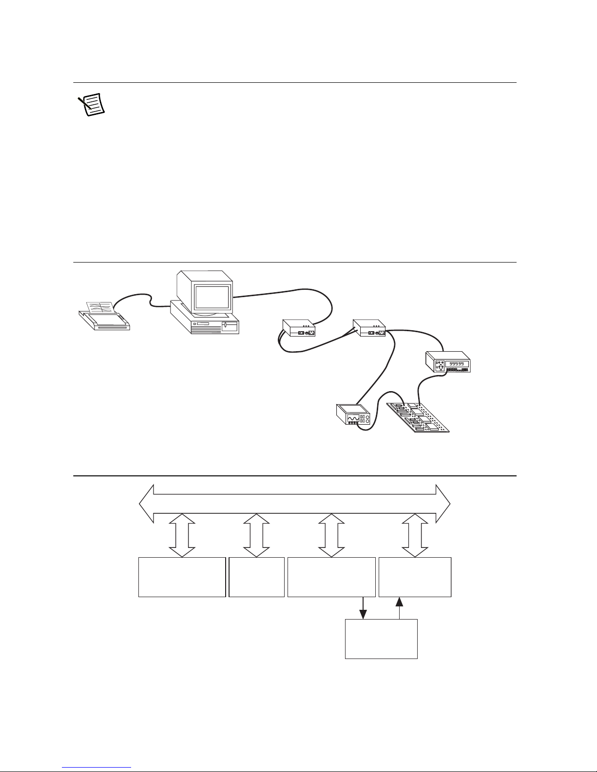
Hardware Overview
Note You cannot use the GPIB-140A or GPIB-140A/2 bus extenders to
communicate with either a GPIB-140 or GPIB-140/2 bus extender. The GPIB-140A
and GPIB-140A/2 bus extenders use a different protocol to communicate with each
other across the fiber optic cable.
The GPIB-140A and GPIB-140A/2 are high-speed bus extenders that you can use in pairs with
fiber-optic cable to connect two separate GPIB systems in a functionally transparent manner.
Although the two bus systems are physically separate, as shown in Figure 1-1, devices logically
appear to be located on the same bus, as shown in Figure 1-2.
Figure 1-1. Typical Extension System (Physical Configuration)
1-2 | ni.com
Figure 1-2. Typical Extension System (Logical Configuration)
Page 11

GPIB-140A User Manual
The GPIB-140A and GPIB-140A/2 bus extenders comply with the specifications of the
ANSI/IEEE Standard 488.1-1987 and the ANSI/IEEE Standard 488.2-1992, including the Find
Listeners protocol. With the GPIB extenders, you can overcome the following two configuration
restrictions imposed by IEEE 488:
• A cable length limit of 20 m total per contiguous bus or 2 m per each device on the bus,
whichever is smaller
• An electrical loading limit of 15 devices per contiguous bus
Each GPIB-140A system extends the GPIB to a maximum distance of 1 km, and each
GPIB-140A/2 system extends the GPIB to a maximum distance of 2 km. Both systems extend
the loading limit to 28 devices (including the GPIB extenders), without sacrificing speed or
performance. You can connect these point-to-point extension systems in series for longer
distances or in star patterns for additional loading.
Using the HS488 protocol, the maximum data transfer rate over the extension is greater than
2.8 Mbytes/s. The GPIB extenders use a buffered transfer technique with a serial extension bus,
which maximizes performance and minimizes the cabling cost. Furthermore, the extender does
not affect the transfer rate between devices on the same side of the extension. The GPIB extender
can also check for errors to make sure that the data transmitted successfully over the fiber-optic
link.
Because the GPIB-140A and GPIB-140A/2 are functionally transparent extenders, the GPIB
communications and control programs that work with an unextended system also work with an
extended system. However, the Parallel Poll Response Modes section in Chapter 3, Configuring
and Using Your Hardware, describes one exception to this transparency in conducting parallel
polls.
Time-Saving Development Tools
Your kit includes the GPIB-140A or GPIB-140A/2 bus extender. In addition, you can order the
NI-488.2, LabWindows™/CVI™, or LabVIEW software from National Instruments to speed
your application development time and make it easier to communicate with your instruments.
The NI-488.2 software supports the concurrent use of multiple types of GPIB hardware. For
example, you can communicate with GPIB devices through a PCI-GPIB, a PCMCIA-GPIB, and
a GPIB-ENET/100 in the same system at the same time. The NI-488.2 software, along with the
GPIB hardware, transforms your computer into a GPIB Talker/Listener/Controller with
complete communications and bus management capability.
LabVIEW is an easy-to-use, graphical programming environment you can use to acquire data
from thousands of different instruments, including IEEE 488.2 devices, VXI devices, serial
devices, PLCs, and plug-in data acquisition boards. After you have acquired raw data, you can
convert it into meaningful results using the powerful data analysis routines in LabVIEW.
LabVIEW also comes with hundreds of instrument drivers, which dramatically reduce software
development time, because you do not have to spend time programming the low-level control of
each instrument.
© National Instruments | 1-3
Page 12

Chapter 1 Introduction
LabWindows/CVI is similar to LabVIEW, except that it combines an interactive, easy-to-use
development approach with the programming power and flexibility of compiled ANSI C code.
The GPIB Analyzer is another optional tool available from National Instruments that is useful
in troubleshooting a variety of IEEE 488 hardware and software problems. With its built-in
time-stamping capability, you can easily determine the throughput and overhead of your GPIB
systems. The GPIB Analyzer software for Windows works with the AT-GPIB/TNT+,
PCI-GPIB+, and NI PCIe-GPIB+ products, which provide GPIB Analyzer support along with
the functionality of a high-performance GPIB Controller.
For ordering information, or to request free demonstration software, contact National
Instruments.
1-4 | ni.com
Page 13

2
Connecting Your Hardware
This chapter describes how to connect your GPIB extender and verify that it is working properly.
Step 1. Verify the DIP Switch Setting
The 3-bit DIP switch sets the operation mode of the GPIB extender. The default switch setting
is for unbuffered transfer mode, latched parallel poll response (PPR), and HS488 disabled mode,
as shown in Figure 2-1.
Figure 2-1. Default DIP Switch Setting
OFF
PARALLEL POLL IMMEDIATE
HS488 ENABLE
BUFFERED TRANSFER
Verify that the DIP switches on your GPIB extender are in these default positions. If you need
to change these settings, refer to Chapter 3, Configuring and Using Your Hardware, for
instructions on how to set the operation mode for your application.
ON
© National Instruments | 2-1
Page 14
Chapter 2 Connecting Your Hardware
Step 2. Connect the Cables
To connect the cables to both GPIB extenders, complete the following steps:
1. Make sure that each GPIB extender is powered off.
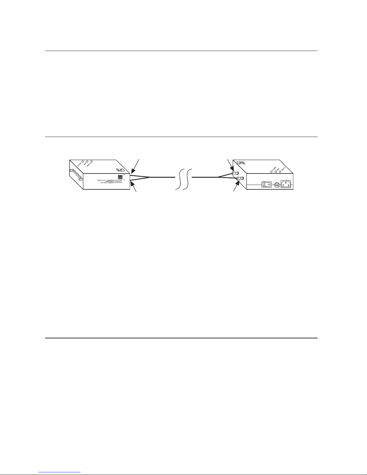
2. Connect the two connectors on each end of the fiber-optic cable to your GPIB extenders, as
follows:
a. As shown in Figure 2-2, align the connector marked T (transmit) with the connector
marked TRANS on the side panel of the GPIB extender. Align the connector marked
R (receive) with the connector marked RCVR on the side panel of the GPIB extender.
Figure 2-2. Connecting the Fiber-Optic Cable to Both GPIB Extenders
GPIB-140A or
GPIB-140A/2
T
R
RCVR
RCVRTRANS
Fiber-Optic Cable
R
GPIB-140A or
GPIB-140A/2
T
TRANS
b. Remove the caps on the connectors.
c. Align the notch on each cable connector to the slot of the fiber-optic connector on the
box.
d. Firmly push in the cable connector and rotate the sleeve clockwise until it locks on to
the side notch of the fiber-optic connector on the box.
3. Connect the end of the extender with the GPIB connector to your GPIB system. Make sure
that you follow all IEEE 488 cabling restrictions. For typical restrictions, refer to the
Configuration Requirements section in Appendix A, GPIB Basics.
4. Plug the utility power cord included with your GPIB extender into an AC outlet of the
correct voltage.
5. Plug the other end of the utility power cord into your GPIB extender.
Step 3. Switch On Your GPIB Extender
Power on each GPIB extender. The POWER LED should light immediately. If the POWER
LED does not light immediately, make sure that power is supplied to your GPIB extender.
The LINK LED lights only when both GPIB extenders are on and the fiber-optic cable is
properly connected between them.
2-2 | ni.com
Page 15
GPIB-140A User Manual
GPIB-140A or
GPIB-140A/2
Fiber-Optic
Cable
TRANS
RCVR
R
R
T
T
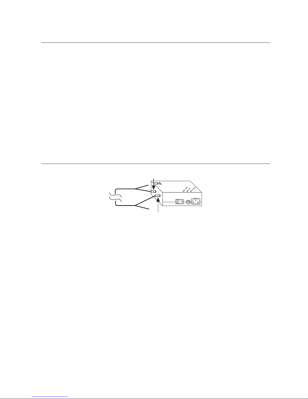
Step 4. Verify the Connection
Each GPIB extender has a self test that determines whether the GPIB extender receivers,
transmitters, and packet transmission and reception circuitry are working properly.
To run the self test, complete the following steps:
1. Power off the GPIB extender.
2. Disconnect the fiber-optic cable from the GPIB extender.
3. Power on the GPIB extender.
The POWER LED lights, indicating that power is supplied to the extender. The LINK
LED remains off.
4. Connect the connector marked T (transmit) on one end of the fiber-optic cable to the
connector marked TRANS on the side panel of the GPIB extender.
5. Connect the connector marked R (receive) on the opposite end of the fiber-optic cable to
the connector marked RCVR on the side panel of the GPIB extender.
Figure 2-3. GPIB Extender Self-Test Configuration
The LINK LED lights, indicating that the cable is connected. The ERROR LED should
remain off, indicating that the GPIB extender is working properly.
6. If the ERROR LED does not remain off, complete the following steps to solve the problem:
a. Verify that the fiber-optic cable is connected to the GPIB extender, as described in
steps 4 and 5. If the problem persists, continue to the next step.
b. Repeat steps 4 and 5 using the unconnected ends of the fiber-optic cable. If switching
the fiber-optic cable connectors solves the problem, you need to replace your
fiber-optic cable. To order a new fiber-optic cable, contact National Instruments. If
switching the fiber-optic cable connectors does not solve the problem, continue to the
next step.
c. If possible, repeat steps 4 and 5 using a different fiber-optic cable. If the problem
persists, you might need to replace your GPIB extender. For more information, contact
National Instruments.
© National Instruments | 2-3
Page 16

3
Configuring and Using
Your Hardware
This chapter describes how to configure and use your GPIB-140A or GPIB-140A/2 system.
Data Transfer Modes
The GPIB extender has two data transfer modes—unbuffered mode and buffered mode. The data
transfer mode determines how data is transmitted across the extension.
Selecting a Data Transfer Mode
To select a data transfer mode, refer to the following descriptions of each mode.
Unbuffered Mode
In unbuffered mode, each data byte is transmitted using the GPIB double-interlocked
handshaking protocol. For long data streams, transfers are slower than transfers using buffered
mode. However, the GPIB extension is transparent in unbuffered mode.
Buffered Mode
In buffered mode, the GPIB extenders use FIFO (first-in-first-out) buffers to buffer data between
the remote and local units. For long data streams, the data throughput is much higher than with
unbuffered mode.
However, a few applications may not operate properly in buffered mode. For example, a GPIB
device on the local side of the extension is addressed to talk, another device on the remote side
is addressed to listen. When the Talker sources data bytes, the GPIB extenders accept the data
bytes and store them in a FIFO buffer. At the same time, the GPIB extenders read data from the
FIFO buffer and source data bytes to the Listener. If the FIFO buffer contains data, the number
of bytes sourced by the Talker differs from the number of bytes accepted by the Listener.
GPIB command bytes are not stored in the FIFO buffers; they are transmitted using the GPIB
double-interlocked handshaking protocol.
© National Instruments | 3-1
Page 17

Chapter 3 Configuring and Using Your Hardware
PARALLEL POLL IMMEDIATE
HS488 ENABLE
BUFFERED TRANSFER
= Not used to set data transfer mode
OFF
ON
Setting the Data Transfer Mode
The two GPIB extenders in your extension system must use the same data transfer mode.
To use buffered mode, set DIP switch 1 to the ON position, as shown in Figure 3-1. To use
unbuffered mode, set DIP switch 1 to the OFF position.
Figure 3-1. DIP Switch Setting for Buffered Mode
HS488 Mode
The GPIB extender can handle data transfers using the HS488 protocol. HS488 transfers data
between two or more devices using a noninterlocked handshaking protocol. You can use HS488
to transfer data at rates higher than rates possible using the IEEE 488 protocol. For more
information about HS488, refer to Appendix B, Introduction to HS488.
Selecting an HS488 Mode
To select an HS488 mode, refer to the following descriptions of each mode.
HS488 Disabled
If you disable HS488, the GPIB extender sources and accepts data using a three-wire handshaking
protocol, even if both the Talker and Listener can transfer data using the HS488 protocol.
HS488 Enabled
After the Talker indicates that it wants to issue HS488 transfers, HS488 is enabled and the GPIB
extender accepts data using the HS488 protocol. Also, when talking, the GPIB extender always
tries to use the HS488 mode. In HS488 mode, FIFO buffers buffer data during HS488 transfers,
even if the data transfer mode is set to unbuffered. When you use the HS488 protocol with the
GPIB extender, you should set the GPIB cable length to 5 m for both the local and the remote
system. To do so, use your IEEE 488.2 software configuration utility.
Setting the HS488 Mode
The two GPIB extenders in your extension system do not need to use the same HS488 mode.
However, the system uses the maximum data transfer rate when both sides in your extension
system use HS488.
3-2 | ni.com
Page 18

GPIB-140A User Manual
To enable HS488, set DIP switch 2 to the ON position, as shown in Figure 3-2. To disable
HS488, set DIP switch 2 to the OFF position.
Figure 3-2. DIP Switch Setting for Enabled HS488
= Not used to set HS488 mode
OFF
PARALLEL POLL IMMEDIATE
HS488 ENABLE
BUFFERED TRANSFER
ON
Parallel Poll Response Modes
According to IEEE 488, devices must respond to a parallel poll within 200 ns after the
Controller-In-Charge (CIC) asserts the Identify (IDY) message—Attention (ATN) and End or
Identify (EOI). The CIC waits at least 2 µs before reading the Parallel Poll Response (PPR). In
many cases, a remote device on an extended system cannot respond to parallel polls this quickly
because of cable propagation delays. To solve this problem, use one of the following two
solutions in your application:
• If possible, specify in your application that the CIC must allow enough time to receive the
response. For more information, refer to the following section, Immediate PPR Mode. If
you are using the NI-488.2 software, you can use the NI-488.2 Configuration utility to set
the amount of time that the CIC waits.
• Execute two consecutive parallel polls and use the second response. For more information,
refer to the Latched PPR Mode section later in this chapter.
Immediate PPR Mode
In immediate PPR mode, the GPIB extenders do not use the internal PPR data register. When a
Controller on the local system asserts IDY, the local extender sends the IDY message to the
remote bus and the response is returned as fast as propagation delays permit. Your application
must allow enough time to receive the response.
Latched PPR Mode
In latched PPR mode, the GPIB extenders use an internal PPR data register. When a Controller
on the local system asserts IDY, the local extender sends the contents of the PPR data register to
the local data lines. At the same time, a parallel poll message is sent to the remote bus. When the
local system unasserts IDY, the PPR from the remote system is loaded into the internal PPR data
register. Consequently, the register always contains the response of the previous complete poll.
To obtain the response of both local and remote systems, your application should execute two
consecutive parallel polls and use the second response.
© National Instruments | 3-3
Page 19

Chapter 3 Configuring and Using Your Hardware
The software driver library of most Controllers contains an easy-to-use parallel poll function.
For example, if the function is called
ibrpp and your application is written in BASIC, the
sequence to execute a poll in latched PPR mode might be similar to the following sequence:
CALL ibrpp (brd0%, ppr%)
CALL ibrpp (brd0%, ppr%)
IF ppr > 0 GOTO 300
Selecting a PPR Mode
To select a PPR mode, consider the type of Controller present in your GPIB system and the
length of cable between the GPIB-140A extenders. However, if your application does not use
parallel polls, you do not need to select a PPR mode.
Some Hewlett Packard GPIB Controllers remain in a parallel poll state with IDY asserted if they
are not performing another function. A change in the response interrupts the application. In some
Controllers, the IDY signal is toggled on and off, and you can change the duration of the signal
to accommodate delayed responses over extenders. If you are using these types of Controllers,
you should set the GPIB extender to immediate PPR mode.
Most other Controllers pulse the IDY signal for approximately 2 µs and expect a response within
that time. If you are using this type of Controller and if the cable between the extenders is longer
than 60 m, you should set the GPIB extender to latched PPR mode. For shorter cable distances,
use immediate PPR mode.
The two GPIB extenders in your extension system do not need to use the same PPR mode. Select
the PPR mode of the local GPIB extender based on the Controllers on the local GPIB system.
Likewise, select the PPR mode of the remote GPIB extender based on the Controllers on the
remote GPIB system. If no Controllers are physically connected to one of the GPIB extenders,
the PPR mode of that GPIB extender has no effect on your system.
Setting the PPR Mode
To use immediate PPR mode, set DIP switch 3 to the ON position, as shown in Figure 3-3. To
use latched PPR mode, set DIP switch 3 to the OFF position.
Figure 3-3. DIP Switch Setting for Immediate PPR Mode
= Not used to set Parallel Poll Response (PPR) mode
OFF
3-4 | ni.com
PARALLEL POLL IMMEDIATE
HS488 ENABLE
BUFFERED TRANSFER
ON
Page 20

GPIB-140A User Manual
Using Your Extension System
After you supply power to both extenders and connect the fiber-optic cable, you can use your
GPIB-140A or GPIB-140A/2 extension system.
Table 3-1 lists the three LEDs that indicate the operational status of each GPIB extender.
Table 3-1. GPIB-140A LEDs
LED Description
POWER Lights if power is supplied to the GPIB extender and the power
switch is in the on position.
LINK Lights if both GPIB extenders are powered on and the transmission
cable is properly connected to both extenders. During operation, the
LINK LED turns off if you disconnect the cable from the receiver of
the GPIB extender, or if you power off either GPIB extender.
ERROR Lights if the GPIB extender receives corrupted data. The ERROR
LED turns off after the GPIB extender starts re-transmission and has
received the first retransmitted data byte without error.
© National Instruments | 3-5
Page 21

4
Message Interpreter
Layer
Message Interpreter
Layer
Packet Translation
Layer
Packet Translation
Layer
Link Management
Layer
Link Management
Layer
Parallel-to-Serial
Conversion Layer
Physical Layer
GPIB BUS #2
GPIB BUS #1
GPIB EXTENDER
GPIB EXTENDER
Transmission
Medium
Physical Layer
Parallel-to-Serial
Conversion Layer
Theory of Operation
This chapter describes how the GPIB extender circuitry operates.
This chapter assumes that you are familiar with GPIB. If you are a first-time user or if you would
like to review the basics about GPIB, refer to Appendix A, GPIB Basics.
Figure 4-1 shows the five layers of a GPIB extender. To form a complete link, you can connect
each layer to the corresponding layer of another extender at the remote side.
Figure 4-1. GPIB Extender Block Diagram
© National Instruments | 4-1
Page 22

Chapter 4 Theory of Operation
Message Interpreter Layer
The Message Interpreter Layer handles the handshake between the GPIB extender and other
devices on the GPIB. At the same time, the layer monitors the activities that occur on the GPIB,
translates them into equivalent local and remote GPIB messages, and sends these messages to
the Packet Translation Layer.
Packet Translation Layer
The Packet Translation Layer converts the messages that it receives to packets and sends them
to the Link Management Layer. It can also receive packets from the Link Management Layer
and convert them back to local or remote GPIB messages.
Link Management Layer
The Link Management Layer receives packets from the Packet Translation Layer. It sends the
packets to the Parallel-to-Serial Conversion Layer and it stores them in a local buffer. If a
transmission error occurs, the Link Management Layer can re-send the packets from this local
buffer. The Link Management Layer also receives packets from the Parallel-to-Serial
Conversion Layer and checks the packets for transmission errors. If the Link Management Layer
does not detect an error, it sends the packets to the Packet Translation Layer. However, if it
detects a transmission error, the it re-transmits the packets.
Parallel-to-Serial Conversion Layer
The Parallel-to-Serial Conversion Layer accepts packets from the Link Management Layer,
converts them into serial data, and sends the data to the Physical Layer. It also extracts serial bits
from the Physical Layer, reconstructs them back into packets, and sends them to the Link
Management Layer.
Physical Layer
The Physical Layer transmits and receives serial data over the fiber-optic link.
4-2 | ni.com
Page 23

A
GPIB Basics
This appendix describes the basic concepts of GPIB, including its physical and electrical
characteristics, and configuration requirements.
The ANSI/IEEE Standard 488.1-1987, also known as General Purpose Interface Bus (GPIB),
describes a standard interface for communication between instruments and controllers from
various vendors. It contains information about electrical, mechanical, and functional
specifications. GPIB is a digital, 8-bit parallel communications interface with data transfer rates
of 1 Mbyte/s and higher, using a three-wire handshake. The bus supports one System Controller,
usually a computer, and up to 14 additional instruments. The ANSI/IEEE Standard 488.2-1992
extends IEEE 488.1 by defining a bus communication protocol, a common set of data codes and
formats, and a generic set of common device commands.
Types of Messages
Interconnected GPIB devices communicate by passing messages through the interface system,
including device-dependent messages and interface messages.
• Device-dependent messages, also called data or data messages, contain device-specific
information, such as programming instructions, measurement results, machine status, and
data files.
• Interface messages, also called commands or command messages, manage the bus itself.
Interface messages initialize the bus, address and unaddress devices, and set device modes
for remote or local programming.
The term command as used here does not refer to device instructions, which are also called
commands. Those device-specific instructions are data messages.
Talkers, Listeners, and Controllers
GPIB devices can be Talkers, Listeners, or Controllers. A Talker sends out data messages.
Listeners receive data messages. The Controller, usually a computer, manages the flow of
information on the bus. It defines the communication links and sends GPIB commands to
devices.
Some devices are capable of playing more than one role. A digital voltmeter, for example, can
be a Talker and a Listener. If your system has a National Instruments GPIB interface and
software installed, it can function as a Talker, Listener, and Controller.
© National Instruments | A-1
Page 24

Appendix A GPIB Basics
The GPIB is like a typical computer bus, except that the typical computer has circuit cards
interconnected via a backplane bus, whereas the GPIB has standalone devices interconnected via
a cable bus.
The role of the GPIB Controller is similar to the role of the CPU of a computer, but a better
analogy is to the switching center of a city telephone system. The switching center (Controller)
monitors the communications network (GPIB). When the center (Controller) notices that a party
(device) wants to make a call (send a data message), it connects the caller (Talker) to the receiver
(Listener).
The Controller addresses a Talker and a Listener before the Talker can send its message to the
Listener. After the message is transmitted, the Controller may unaddress both devices.
Some bus configurations do not require a Controller. For example, one device may always be a
Talker (called a Talk-only device) and there may be one or more Listen-only devices.
A Controller is necessary when the active or addressed Talker or Listener must be changed. The
Controller function is usually handled by a computer.
With the GPIB interface board and its software your personal computer plays all three roles.
• Controller—to manage the GPIB
• Talker—to send data
• Listener—to receive data
Controller-In-Charge and System Controller
You can have multiple Controllers on the GPIB, but only one Controller at a time can be the
active Controller, or Controller-In-Charge (CIC). The CIC can be either active or inactive
(standby). Control can pass from the current CIC to an idle Controller, but only the System
Controller, usually a GPIB interface, can make itself the CIC.
GPIB Signals and Lines
Devices on the bus communicate by sending messages. Signals and lines transfer these messages
across the GPIB interface, which consists of 16 signal lines and 8 ground return (shield drain)
lines. The 16 signal lines are discussed in the following sections.
Data Lines
Eight data lines, DIO1 through DIO8, carry both data and command messages.
A-2 | ni.com
Page 25

GPIB-140A User Manual
Handshake Lines
Three hardware handshake lines asynchronously control the transfer of message bytes between
devices. This process is a three-wire interlocked handshake, and it guarantees that devices send
and receive message bytes on the data lines without transmission error. Table A-1 summarizes
the GPIB handshake lines.
Table A-1. GPIB Handshake Lines
Line Description
NRFD
(not ready for data)
NDAC
(not data accepted)
DAV
(data valid)
Listening device is ready/not ready to receive a message byte. Also
used by the Talker to signal high-speed GPIB transfers.
Listening device has/has not accepted a message byte.
Talking device indicates signals on data lines are stable (valid) data.
Interface Management Lines
Five hardware lines manage the flow of information across the bus. Table A-2 summarizes the
GPIB interface management lines.
Table A-2. GPIB Interface Management Lines
Line Description
AT N
(attention)
IFC
(interface clear)
Controller drives ATN true when it sends commands and false when it
sends data messages.
System Controller drives the IFC line to initialize the bus and make itself
CIC.
REN
(remote enable)
SRQ
(service request)
EOI
(end or identify)
System Controller drives the REN line to place devices in remote or
local program mode.
Any device can drive the SRQ line to asynchronously request service
from the Controller.
Talker uses the EOI line to mark the end of a data message. Controller
uses the EOI line when it conducts a parallel poll.
© National Instruments | A-3
Page 26

Appendix A GPIB Basics
Physical and Electrical Characteristics
Devices are usually connected with a cable assembly consisting of a shielded 24-conductor cable
with both a plug and receptacle connector at each end, as shown in Figure A-1. With this design,
you can link devices in a linear configuration, a star configuration, or a combination of the
two configurations. Figure A-2 shows the linear and star configurations.
Figure A-1. GPIB Connector and the Signal Assignment
13
DIO1
DIO2
DIO3
DIO4
EOI
DAV
NRFD
NDAC
IFC
SRQ
ATN
SHIELD
1
14
2
15
3
16
4
17
5
18
6
19
7
20
8
21
9
22
10
23
11
24
12
DIO5
DIO6
DIO7
DIO8
REN
GND (TW PAIR W/DAV)
GND (TW PAIR W/NRFD)
GND (TW PAIR W/NDAC)
GND (TW PAIR W/IFC)
GND (TW PAIR W/SRQ)
GND (TW PAIR W/ATN)
SIGNAL GROUND
A-4 | ni.com
Page 27

Figure A-2. Linear and Star System Configuration
Device A
GPIB-140A User Manual
Device B
Device C
a. Linear Configuration
b. Star Configuration
Device DDevice A
Device CDevice B
The standard connector is the Amphenol or Cinch Series 57 Microribbon or Amp Champ type.
For special interconnection applications, you use an adapter cable using a non-standard cable
and/or connector.
The GPIB uses negative logic with standard TTL (transistor-transistor logic) level. For example,
when DAV is true, it is a TTL low level (≤ 0.8 V), and when DAV is false, it is a TTL high level
(≥ 2.0 V).
Configuration Requirements
To achieve the high data transfer rate that the GPIB was designed for, you must limit the number
of devices on the bus and the physical distance between devices. The following restrictions are
typical:
• A maximum separation of 4 m between any two devices and an average separation of 2 m
over the entire bus.
• A maximum total cable length of 20 m.
• A maximum of 15 devices connected to each bus, with at least two-thirds powered on.
For high-speed operation, the following restrictions apply:
• All devices in the system must be powered on.
• Cable lengths must be as short as possible with up to a maximum of 15 m of cable for each
system.
• There must be at least one equivalent device load per meter of cable.
© National Instruments | A-5
Page 28

Appendix A GPIB Basics
If you want to exceed these limitations, you can use a bus expander to increase the number of
device loads. You can order bus expanders from National Instruments.
A-6 | ni.com
Page 29

B
Introduction to HS488
This appendix describes HS488 and the sequence of events in high-speed data transfers.
National Instruments has designed a high-speed data transfer protocol for IEEE 488 called
HS488. This protocol increases performance for GPIB reads and writes up to 8 Mbytes/s,
depending on your system.
If HS488 is enabled, the TNT4882C hardware implements high-speed transfers automatically
when communicating with HS488 instruments. If you attempt to enable HS488 on a GPIB
interface that does not have the TNT4882C hardware, the ECAP error code is returned.
Objectives
The following sections describe the objectives of HS488.
Faster Transfer Rates
HS488 enables transfer rates that are substantially faster than the IEEE 488 standard. In small
systems, the raw transfer rate can be up to 8 Mbytes/s. The faster raw transfer rates improve
system throughput in systems where devices send long blocks of data. The physical limitations
of the cabling system, however, limit the transfer rate.
Compatibility with IEEE 488 Devices
HS488 is a superset of the IEEE 488 standard; thus, you can mix IEEE 488.1, IEEE 488.2, and
HS488 devices in the same system.
When connected to an HS488 device, the Controller does not need to be capable of HS488
noninterlocked transfers. While ATN is asserted, the Controller sources multiline messages to
HS488 devices just as it sources multiline messages to any IEEE 488 devices.
Automatic HS488 Detection
Addressed HS488 devices can detect whether other addressed devices are capable of HS488
transfers without the interaction of the Controller.
Compatibility with the IEEE 488.2 Standard
The HS488 protocol requires no changes to the IEEE 488.2 standard. Also, HS488 devices do
not need to be compliant with IEEE 488.2.
© National Instruments | B-1
Page 30

Appendix B Introduction to HS488
Same Cabling Restrictions as IEEE 488.1
Systems that meet the IEEE 488.1 requirements for high-speed operation also meet the HS488
requirements. HS488 cabling requirements are also the same as the requirements in the
IEEE 488.1 standard.
However, using HS488 does not reduce software overhead. Also, system throughput increases
depend on data block size.
IEEE 488.1 Requirements for High-Speed
Operation (T1 Delay ≥ 350 ns)
The IEEE 488.1 standard requires that devices used in high-speed operation must use three-state,
48 mA drivers on most signals. Each device must add no more than 50 pF capacitance on each
signal, and all devices must be powered on.
The total cable length in a system must be no more than 15 m, or 1 m times the number of devices
in the system.
HS488 System Requirements
An HS488 system must meet the IEEE 488.1 requirements and it must implement the following
three new interface functions:
• Talking devices must use the Source Handshake Extended (SHE) interface function, which
is an extension of the IEEE 488.1 SH function.
• Listening devices must use the Acceptor Handshake Extended (AHE) interface function,
which is an extension of the IEEE 488.1 AH function. Accepting devices must have a
buffer of at least 3 bytes to store received data.
• HS488 devices must implement the Configuration (CF) interface function. At system
power on, the Controller uses previously undefined multiline messages to configure HS488
devices. The CF function enables devices to interpret these multiline messages.
B-2 | ni.com
Page 31

GPIB-140A User Manual
~DIO18
(composite)
~DAV
~NFRD
~NDAC
HS488 Transfers
Sequence of Events in Data Transfers
Figure B-1 shows a typical IEEE 488.1 data transfer.
Figure B-1. IEEE 488.1 Transfers
IEEE 488.1 Three-Wire Transfers
~DIO18
(composite)
~DAV
~NFRD
~NDAC
Figure B-2 shows an HS488 data transfer. The HS488 protocol modifies the IEEE 488.1 SH and
AH functions. At the beginning of each data transfer, the HS488 SHE and AHE functions
determine whether all active Talkers and Listeners are capable of HS488 transfers. If the
addressed devices are HS488-capable, they use the HS488 noninterlocked handshake protocol
for that data transfer. If any addressed device is not HS488-capable, the transfer continues using
the standard three-wire handshake.
Figure B-2. HS488 Transfers
© National Instruments | B-3
Page 32

Appendix B Introduction to HS488
Case 1: Talker and Listener Are HS488-Capable
Figure B-3 and the following steps describe a typical sequence of events in an HS488 data
transfer in which both the Talker and Listener are HS488-capable.
Figure B-3. HS488-Capable Talker and Listener
erred
T13T1 T14
Second byte transferred
(using high-speed mode).
~ATN
~DIO18
(composite)
~DAV
~NFRD
~NDAC
The sending device uses this high
speed capable signal (the momentary,
low-going pulse on ~NRFD) to tell the
receiving device that the sending
device is capable of sending data
using the high-speed handshake.
First byte transf
(us
ing 488.1 handshake).
Lack of low-going transition on
~NRFD indicates that all receiving
devices are high-speed capable.
1. The Controller addresses devices and becomes Standby Controller by unasserting ATN.
2. The Listener asserts NDAC and NRFD.
3. The Listener unasserts NRFD as it becomes ready to accept a byte.
4. After allowing time for the Listener to detect NRFD unasserted, the Talker indicates that it
is HS488-capable by sending the HSC message. To send the HSC message true, the Talker
asserts the NRFD signal.
5. After allowing time for the Listener to respond to the HSC message, the Talker sends the
HSC message false. To send the HSC message false, the Talker unasserts the NRFD signal.
6. When the Talker has a byte ready to send, it drives the data on the DIO signal lines, allows
some settling time, and asserts DAV.
7. The Listener unasserts NDAC. HS488-capable Listeners do not assert NRFD as IEEE 488.1
devices would, so the Talker determines that the addressed Listener is HS488-capable.
8. The Talker unasserts DAV and drives the next data byte on the GPIB.
9. After allowing some settling time, the Talker asserts DAV.
10. The Listener latches the byte in response to the assertion (falling) edge of DAV.
11. After allowing some hold time, the Talker unasserts DAV and drives the next data byte on
the DIO signal lines.
12. Steps 9-11 are repeated for each data byte.
B-4 | ni.com
Page 33

GPIB-140A User Manual
Low-going transition on ~NRFD
indicates that not all receiving
devices are high-speed capable.
High-speed capable signal
~ATN
~DIO18
(composite)
~DAV
~NFRD
~NDAC
T1
Case 2: Talker Is HS488-Capable, But Listener Is Not
HS488-Capable
Figure B-4 and the following steps describe a typical sequence of events in an HS488 data
transfer in which the Talker is HS488-capable, but the Listener is not.
Figure B-4. HS488-Capable Talker
Steps 1-6 are identical to steps 1-6 in Case 1: Talker and Listener Are HS488-Capable. The
Listener ignores the HSC message from the Talker.
Then, the IEEE 488.1 Listener enters ACDS and asserts NRFD. As a result, the Talker
determines that the addressed Listener is not HS488-capable. The Talker sources bytes using the
IEEE 488.1 protocol.
© National Instruments | B-5
Page 34

Appendix B Introduction to HS488
~ATN
~DIO18
(composite)
~DAV
~NFRD
~NDAC
T1
Case 3: Talker Is Not HS488-Capable, But Listener Is
HS488-Capable
The Talker does not send an HSC message to the Listener, but sources bytes using the
IEEE 488.1 protocol.
The addressed Listener (HS488 or IEEE 488.1) accepts bytes using the IEEE 488.1 standard
three-wire handshake, as shown in Figure B-5.
Figure B-5. Listener Is HS488-Capable
System Configuration
The HS488 AHE and SHE interface functions depend on several time delays. Some of these
delays are a function of the total system cable length.
The Controller must communicate this system configuration data to HS488 devices after the
system powers on. The Controller configures HS488 devices by sourcing the following
two multiline messages while ATN is true:
• Configuration Enable (CFE)—The Controller sends the CFE message by driving a bit
pattern (1E hex) that the IEEE 488.1 standard does not define on the DIO signal lines. The
CFE message enables HS488 devices to interpret the SCG message that follows.
• Secondary Command Group (SCG)—This message contains the configuration data. The
Secondary Command has the bit pattern 6n hex, where n is the meters of cable in the
system. The SCG includes CFG1-CFG15 in Appendix C, Multiline Interface Messages.
B-6 | ni.com
Page 35

C
Multiline Interface Messages
This appendix lists the multiline interface messages and describes the mnemonics and messages
that correspond to the interface functions.
The multiline interface messages are commands defined by the IEEE 488 standard. The messages
are sent and received with ATN asserted. The interface functions include initializing the bus,
addressing and unaddressing devices, and setting device modes for local or remote programming.
For more information about these messages, refer to the ANSI/IEEE Standard 488.1-1987,
IEEE Standard Digital Interface for Programmable Instrumentation.
Table C-1. Multiline Interface Messages
Hex Dec ASCII Message Hex Dec ASCII Message
00 0 NUL — 20 32 SP MLA0
01 1 SOH GTL 21 33 ! MLA1
02 2 STX — 22 34 " MLA2
03 3 ETX — 23 35 # MLA3
04 4 EOT SDC 24 36 $ MLA4
05 5 ENQ PPC 25 37 % MLA5
06 6 ACK — 26 38 & MLA6
07 7 BEL — 27 39 ' MLA7
08 8 BS GET 28 40 ( MLA8
09 9 HT TCT 29 41 ) MLA9
0A 10 LF — 2A 42 * MLA10
0B 11 VT — 2B 43 + MLA11
0C 12 FF — 2C 44 , MLA12
0D 13 CR — 2D 45 - MLA13
0E 14 SO — 2E 46 . MLA14
0F 15 SI — 2F 47 / MLA15
10 16 DLE — 30 48 0 MLA16
11 17 DC1 LLO 31 49 1 MLA17
12 18 DC2 — 32 50 2 MLA18
13 19 DC3 — 33 51 3 MLA19
© National Instruments | C-1
Page 36

Appendix C Multiline Interface Messages
Table C-1. Multiline Interface Messages (Continued)
Hex Dec ASCII Message Hex Dec ASCII Message
14 20 DC4 DCL 34 52 4 MLA20
15 21 NAK PPU 35 53 5 MLA21
16 22 SYN — 36 54 6 MLA22
17 23 ETB — 37 55 7 MLA23
18 24 CAN SPE 38 56 8 MLA24
19 25 EM SPD 39 57 9 MLA25
1A 26 SUB — 3A 58 : MLA26
1B 27 ESC — 3B 59 ; MLA27
1C 28 FS — 3C 60 < MLA28
1D 29 GS — 3D 61 = MLA29
1E 30 RS — 3E 62 > MLA30
1F 31 US CFE 3F 63 ? UNL
40 64 @ MTA0 60 96 ` MSA0, PPE
41 65 A MTA1 61 97 a MSA1, PPE, CFG1
42 66 B MTA2 62 98 b MSA2, PPE, CFG2
43 67 C MTA3 63 99 c MSA3, PPE, CFG3
44 68 D MTA4 64 100 d MSA4, PPE, CFG4
45 69 E MTA5 65 101 e MSA5, PPE, CFG5
46 70 F MTA6 66 102 f MSA6, PPE, CFG6
47 71 G MTA7 67 103 g MSA7, PPE, CFG7
48 72 H MTA8 68 104 h MSA8, PPE, CFG8
49 73 I MTA9 69 105 i MSA9, PPE, CFG9
4A 74 J MTA10 6A 106 j MSA10, PPE, CFG10
4B 75 K MTA11 6B 107 k MSA11, PPE, CFG11
4C 76 L MTA12 6C 108 l MSA12, PPE, CFG12
4D 77 M MTA13 6D 109 m MSA13, PPE, CFG13
4E 78 N MTA14 6E 110 n MSA14, PPE, CFG14
4F 79 O MTA15 6F 111 o MSA15, PPE, CFG15
50 80 P MTA16 70 112 p MSA16, PPD
51 81 Q MTA17 71 113 q MSA17, PPD
52 82 R MTA18 72 114 r MSA18, PPD
C-2 | ni.com
Page 37

GPIB-140A User Manual
Table C-1. Multiline Interface Messages (Continued)
Hex Dec ASCII Message Hex Dec ASCII Message
53 83 S MTA19 73 115 s MSA19, PPD
54 84 T MTA20 74 116 t MSA20, PPD
55 85 U MTA21 75 117 u MSA21, PPD
56 86 V MTA22 76 118 v MSA22, PPD
57 87 W MTA23 77 119 w MSA23, PPD
58 88 X MTA24 78 120 x MSA24, PPD
59 89 Y MTA25 79 121 y MSA25, PPD
5A 90 Z MTA26 7A 122 z MSA26, PPD
5B 91 [ MTA27 7B 123 { MSA27, PPD
5C 92 \ MTA28 7C 124 | MSA28, PPD
5D 93 ] MTA29 7D 125 } MSA29, PPD
5E 94 ^ MTA30 7E 126 ~ MSA30, PPD
5F 95 _ UNT 7F 127 DEL —
Multiline Interface Message Definitions
CFE * Configuration Enable
CFG * Configure
DCL Device Clear
GET Group Execute Trigger
GTL Go To Local
LLO Local Lockout
MLA My Listen Address
MSA My Secondary Address
MTA My Talk Address
P P D Parallel Poll Disable
P P E Parallel Poll Enable
P P U Parallel Poll Unconfigure
S D C Selected Device Clear
S P D Serial Poll Disable
S P E Serial Poll Enable
T C T Take Control
U N L Unlisten
U N T Untalk
PPC Parallel Poll Configure
*
This multiline interface message is a proposed extension to the IEEE 488 specification to support the
HS488 protocol.
© National Instruments | C-3
Page 38

D
Specifications
This appendix lists the specifications and characteristics of the GPIB extender.
System Configuration
Distance per extension
GPIB-140A............................................... Up to 1 km
GPIB-140A/2............................................ Up to 2 km
Loading per extension ...................................... Up to 13 additional devices (28 total devices in
the extension system, including the extenders)
Multiple extensions........................................... Permitted in any combination of star or linear
pattern
Performance Characteristics
Maximum transfer rate
Buffered mode, non-HS488...................... > 1.1 Mbytes/s
HS488 handshake ..................................... > 2.8 Mbytes/s
Unbuffered mode...................................... > 200 kbytes/s
Functionality ..................................................... Transparent GPIB operation except for latched
parallel polls
Interlocked IEEE 488 handshake ..................... Maintained across the extension in unbuffered
mode
IEEE 488 capability identification codes
SH1 ........................................................... Complete Source Handshake
AH1 .......................................................... Complete Acceptor Handshake
T5, TE5 ..................................................... Complete Talker
L3, LE3 ..................................................... Complete Listener
SR1 ........................................................... Complete Service Request
RL1 ........................................................... Complete Remote Local
PP1, 2........................................................ Complete Parallel Poll
DC1........................................................... Complete Device Clear
DT1........................................................... Complete Device Trigger
C1-5 .......................................................... Complete Controller
E2.............................................................. Tri-state GPIB driver
HS488 capability identification codes
SHE........................................................... HS488 Source Handshake
AHE .......................................................... HS488 Acceptor Handshake
© National Instruments | D-1
Page 39

Appendix D Specifications
Operational Characteristics
Architecture ...................................................... Point-to-point (not multi-drop) transmission
Operating modes ...............................................Buffered or unbuffered (interlocked) mode
HS488 modes....................................................Enabled HS488 or disabled HS488 mode
Parallel Poll Response modes ...........................Immediate Parallel Poll Response mode or
latched Parallel Poll Response mode
Electrical Characteristics
Transmission interface unit
GPIB-140A ............................................... Optical transmitter and receiver
(HFBR1414, HFBR2416, or equivalent) with
ST-style optical cable connectors
GPIB-140A/2 ............................................Optical transmitter and receiver
(HFBR1312, HFBR1316, or equivalent) with
ST-style optical cable connectors
GPIB interface load ..........................................Two standard loads, AC and DC
Power supply unit
100-120 VAC ............................................50-60 Hz
220-240 VAC ............................................50-60 Hz
Maximum current requirement
100-120 VAC ............................................135 mA
220-240 VAC ............................................100 mA
Fuse rating and type
100-120 VAC ............................................T 0.5A 250V
220-240 VAC ............................................T 0.3A 350V
Environmental Characteristics
Operating temperature ...................................... 0 to 40 °C
Storage temperature .......................................... -20 to 70 °C
Relative humidity..............................................10% to 90%, noncondensing
D-2 | ni.com
Page 40

GPIB-140A User Manual
Environmental Specifications
EMI................................................................... FCC Class A Verified
Maximum altitude............................................. 2,000 m (800 mbar), at 25 °C ambient
temperature
Pollution Degree ............................................... 2
Indoor use only.
Physical Characteristics
Overall case size (dimensions) ......................... 3.5 × 5.65 × 1.62 in.
(8.89 × 14.35 × 4.11 cm)
Case material .................................................... All metal enclosure
Weight ............................................................... 0.55 lb (0.25 kg)
GPIB cable........................................................ Type X2 shielded
Transmission cable
GPIB-140A............................................... 3.0 × 6.5 mm cable diameter
62.5/125 micron core/clad with NA = 0.275
850 nm operating wavelength
3.0 dB/km attenuation
Duplex style, terminated with ST-style
connectors
GPIB-140A/2............................................ 3.0 × 6.5 mm cable diameter
62.5/125 micron core/clad with NA = 0.275
1300 nm operating wavelength
1 dB/km attenuation
Duplex style, terminated with ST-style
connectors
1
Caution Clean the hardware with a soft, nonmetallic brush. Make sure that the
hardware is completely dry and free from contaminants before returning it to service.
1
To meet FCC emission limits for this device, you must use a shielded GPIB cable. If you operate this
equipment with a non-shielded cable, it may interfere with radio and television reception.
© National Instruments | D-3
Page 41

Appendix D Specifications
Safety
This product is designed to meet the requirements of the following standards of safety for
information technology equipment:
• IEC 60950-1, EN 60950-1
• UL 60950-1, CSA 60950-1
Caution The protection provided by the GPIB 140A can be impaired if it is used
in a manner not described in this document.
Note For UL and other safety certifications, refer to the product label or the Online
Product Certification section.
Electromagnetic Compatibility
This product meets the requirements of the following EMC standards for electrical equipment
for measurement, control, and laboratory use:
• EN 61326 (IEC 61326): Class A emissions; Basic immunity
• EN 55011 (CISPR 11): Group 1, Class A emissions
• AS/NZS CISPR 11: Group 1, Class A emissions
• FCC 47 CFR Part 15B: Class A emissions
• ICES-001: Class A emissions
Note For the standards applied to assess the EMC of this product, refer to the
Online Product Certification section.
Note For EMC compliance, operate this device with shielded cabling.
CE Compliance
This product meets the essential requirements of applicable European Directives as follows:
• 2006/95/EC; Low-Voltage Directive (safety)
• 2004/108/EC; Electromagnetic Compatibility Directive (EMC)
Online Product Certification
Refer to the product Declaration of Conformity (DoC) for additional regulatory compliance
information. To obtain product certifications and the DoC for this product, visit
certification
Certification column.
, search by model number or product line, and click the appropriate link in the
ni.com/
D-4 | ni.com
Page 42

GPIB-140A User Manual
⬉ᄤֵᙃѻક∵ᶧࠊㅵ⧚ࡲ⊩ ˄Ё
RoHS
˅
Ёᅶ᠋
National Instruments
ヺড়Ё⬉ᄤֵᙃѻકЁ䰤ࠊՓ⫼ᶤѯ᳝ᆇ⠽䋼ᣛҸ
(RoHS)
DŽ݇Ѣ
National Instruments
Ё
RoHS
ড়㾘ᗻֵᙃˈ䇋ⱏᔩ
ni.com/
environment/rohs_china
DŽ
(For information about China RoHS compliance,
go to
ni.com/environment/rohs_china
.)
Environmental Management
NI is committed to designing and manufacturing products in an environmentally responsible
manner. NI recognizes that eliminating certain hazardous substances from our products is
beneficial to the environment and to NI customers.
For additional environmental information, refer to the Minimize Our Environmental Impact web
page at
directives with which NI complies, as well as other environmental information not included in
this document.
Waste Electrical and Electronic Equipment (WEEE)
ni.com/environment. This page contains the environmental regulations and
EU Customers At the end of the product life cycle, all products must be sent to
a WEEE recycling center. For more information about WEEE recycling centers,
National Instruments WEEE initiatives, and compliance with WEEE Directive
2002/96/EC on Waste and Electronic Equipment, visit
.
weee
ni.com/environment/
© National Instruments | D-5
Page 43

E
Technical Support and
Professional Services
Log in to your National Instruments ni.com User Profile to get personalized access to your
services. Visit the following sections of ni.com for technical support and professional services:
• Support—Technical support at
– Self-Help Technical Resources—For answers and solutions, visit
support
manuals, step-by-step troubleshooting wizards, thousands of example programs,
tutorials, application notes, instrument drivers, and so on. Registered users also
receive access to the NI Discussion Forums at
Engineers make sure every question submitted online receives an answer.
– Standard Service Program Membership—This program entitles members to direct
access to NI Applications Engineers via phone and email for one-to-one technical
support, as well as exclusive access to self-paced online training modules at ni.com/
self-paced-training
membership in the Standard Service Program (SSP) with the purchase of most
software products and bundles including NI Developer Suite. NI also offers flexible
extended contract options that guarantee your SSP benefits are available without
interruption for as long as you need them. Visit
For information about other technical support options in your area, visit
services
• Training and Certification—Visit
program information. You can also register for instructor-led, hands-on courses at locations
around the world.
for software drivers and updates, a searchable KnowledgeBase, product
, or contact your local office at ni.com/contact.
ni.com/support includes the following resources:
ni.com/
ni.com/forums. NI Applications
. All customers automatically receive a one-year
ni.com/ssp for more information.
ni.com/
ni.com/training for training and certification
• System Integration—If you have time constraints, limited in-house technical resources, or
other project challenges, National Instruments Alliance Partner members can help. To learn
more, call your local NI office or visit
You also can visit the Worldwide Offices section of
office Web sites, which provide up-to-date contact information, support phone numbers, email
addresses, and current events.
ni.com/alliance.
ni.com/niglobal to access the branch
© National Instruments | E-1
Page 44

Glossary
Symbol Prefix Value
ppico10
nnano10
μ
micro 10
m milli 10
k kilo 10
Mmega10
Ggiga10
Ttera10
Symbols
° degrees
%percent
-12
-9
-6
-3
3
6
9
12
A
Aamperes
AC alternating current
AHE HS488 Acceptor Handshake Extended interface function
ANSI American National Standards Institute
ASCII American Standards Code for Information Interchange
ASIC application-specific integrated circuit
ATN Attention
© National Instruments | G-1
Page 45

Glossary
C
CCelsius
CIC Controller-In-Charge
CPU central processing unit
CSA Canadian Standards Association
D
DAV data valid
dB decibels
DC direct current
DIO digital input/output
DIP dual inline package
E
EOI End or Identify
EOS End of String
F
FFarads
FCC Federal Communications Commission
FIFO first-in-first-out
G-2 | ni.com
Page 46

G
ggrams
GPIB General Purpose Interface Bus
H
hex hexadecimal
Hz hertz
I
IDY Identify
IEC International Electrotechnical Commission
GPIB-140A User Manual
IEEE Institute of Electrical and Electronic Engineers
IFC Interface Clear
in. inches
L
lb pounds
LED light-emitting diode
M
m meters
S
s seconds
SHE HS488 Source Handshake Extended interface function
© National Instruments | G-3
Page 47

Glossary
T
TTL transistor-transistor logic
U
UL Underwriter’s Laboratories
V
V volts
VAC volts alternating current
G-4 | ni.com
 Loading...