

Page 1

GPIB
GPIB-120B User Manual
GPIB-120B User Manual
February 2019
371851C-01
Page 2

Support
Worldwide Technical Support and Product Information
ni.com
Worldwide Offices
ni.com/niglobal to access the branch office websites, which provide up-to-date
Visit
contact information, support phone numbers, email addresses, and current events.
National Instruments Corporate Headquarters
11500 North Mopac Expressway Austin, Texas 78759-3504 USA Tel: 512 683 0100
For further support information, refer to the NI Services appendix. To comment on NI
documentation, refer to the NI website at ni.com/info and enter the Info Code feedback.
© 1999–2019 National Instruments. All rights reserved.
Page 3

Legal Information
Limited Warranty
This document is provided ‘as is’ and is subject to being changed, without notice, in future editions. For the latest version,
refer to
ni.com/manuals. NI reviews this document carefully for technical accuracy; however, NI MAKES NO EXPRESS
OR IMPLIED WARRANTIES AS TO THE ACCURACY OF THE INFORMATION CONTAINED HEREIN AND
SHALL NOT BE LIABLE FOR ANY ERRORS.
NI warrants that its hardware products will be free of defects in materials and workmanship that cause the product to fail to
substantially conform to the applicable NI published specifications for one (1) year from the date of invoice.
For a period of ninety (90) days from the date of invoice, NI warrants that (i) its software products will perform substantially
in accordance with the applicable documentation provided with the software and (ii) the software media will be free from
defects in materials and workmanship.
If NI receives notice of a defect or non-conformance during the applicable warranty period, NI will, in its discretion: (i) repair
or replace the affected product, or (ii) refund the fees paid for the affected product. Repaired or replaced Hardware will be
warranted for the remainder of the original warranty period or ninety (90) days, whichever is longer. If NI elects to repair or
replace the product, NI may use new or refurbished parts or products that are equivalent to new in performance and reliability
and are at least functionally equivalent to the original part or product.
You must obtain an RMA number from NI before returning any product to NI. NI reserves the right to charge a fee for
examining and testing Hardware not covered by the Limited Warranty.
This Limited Warranty does not apply if the defect of the product resulted from improper or inadequate maintenance,
installation, repair, or calibration (performed by a party other than NI); unauthorized modification; improper environment;
use of an improper hardware or software key; improper use or operation outside of the specification for the product; improper
voltages; accident, abuse, or neglect; or a hazard such as lightning, flood, or other act of nature.
THE REMEDIES SET FORTH ABOVE ARE EXCLUSIVE AND THE CUSTOMER’S SOLE REMEDIES, AND SHALL
APPLY EVEN IF SUCH REMEDIES FAIL OF THEIR ESSENTIAL PURPOSE.
EXCEPT AS EXPRESSLY SET FORTH HEREIN, PRODUCTS ARE PROVIDED "AS IS" WITHOUT WARRANTY OF
ANY KIND AND NI DISCLAIMS ALL WARRANTIES, EXPRESSED OR IMPLIED, WITH RESPECT TO THE
PRODUCTS, INCLUDING ANY IMPLIED WARRANTIES OF MERCHANTABILITY, FITNESS FOR A
PARTICULAR PURPOSE, TITLE OR NON-INFRINGEMENT, AND ANY WARRANTIES THAT MAY ARISE FROM
USAGE OF TRADE OR COURSE OF DEALING. NI DOES NOT WARRANT, GUARANTEE, OR MAKE ANY
REPRESENTATIONS REGARDING THE USE OF OR THE RESULTS OF THE USE OF THE PRODUCTS IN TERMS
OF CORRECTNESS, ACCURACY, RELIABILITY, OR OTHERWISE. NI DOES NOT WARRANT THAT THE
OPERATION OF THE PRODUCTS WILL BE UNINTERRUPTED OR ERROR FREE.
In the event that you and NI have a separate signed written agreement with warranty terms covering the products, then the
warranty terms in the separate agreement shall control.
Copyright
Under the copyright laws, this publication may not be reproduced or transmitted in any form, electronic or mechanical,
including photocopying, recording, storing in an information retrieval system, or translating, in whole or in part, without the
prior written consent of National Instruments Corporation.
National Instruments respects the intellectual property of others, and we ask our users to do the same. NI software is protected
by copyright and other intellectual property laws. Where NI software may be used to reproduce software or other materials
belonging to others, you may use NI software only to reproduce materials that you may reproduce in accordance with the
terms of any applicable license or other legal restriction.
End-User License Agreements and Third-Party Legal Notices
You can find end-user license agreements (EULAs) and third-party legal notices in the following locations:
• Notices are located in the
directories.
• EULAs are located in the
•Review
installers built with NI products.
<National Instruments>\_Legal Information.txt for information on including legal information in
U.S. Government Restricted Rights
If you are an agency, department, or other entity of the United States Government (“Government”), the use, duplication,
reproduction, release, modification, disclosure or transfer of the technical data included in this manual is governed by the
Restricted Rights provisions under Federal Acquisition Regulation 52.227-14 for civilian agencies and Defense Federal
Acquisition Regulation Supplement Section 252.227-7014 and 252.227-7015 for military agencies.
Trademarks
Refer to the NI Trademarks and Logo Guidelines at ni.com/trademarks for more information on NI trademarks.
ARM, Keil, and µVision are trademarks or registered of ARM Ltd or its subsidiaries.
LEGO, the LEGO logo, WEDO, and MINDSTORMS are trademarks of the LEGO Group.
TETRIX by Pitsco is a trademark of Pitsco, Inc.
FIELDBUS FOUNDATION
EtherCAT
®
is a registered trademark of and licensed by Beckhoff Automation GmbH.
<National Instruments>\_Legal Information and <National Instruments>
<National Instruments>\Shared\MDF\Legal\license directory.
™
and FOUNDATION™ are trademarks of the Fieldbus Foundation.
Page 4

CANopen® is a registered Community Trademark of CAN in Automation e.V.
™
DeviceNet
and EtherNet/IP™ are trademarks of ODVA.
Go!, SensorDAQ, and Vernier are registered trademarks of Vernier Software & Technology. Vernier Software & Technology
vernier.com are trademarks or trade dress.
and
Xilinx is the registered trademark of Xilinx, Inc.
Taptite and Trilobular are registered trademarks of Research Engineering & Manufacturing Inc.
®
FireWire
Linux
Handle Graphics
Simulink Coder
Tektronix
The Bluetooth
The ExpressCard
is the registered trademark of Apple Inc.
®
is the registered trademark of Linus Torvalds in the U.S. and other countries.
®
, MATLAB®, Simulink®, Stateflow®, and xPC TargetBox® are registered trademarks, and
™
, TargetBox™, and Target Language Compiler™ are trademarks of The MathWorks, Inc.
®
, Tek, and Tektronix, Enabling Technology are registered trademarks of Tektronix, Inc.
®
word mark is a registered trademark owned by the Bluetooth SIG, Inc.
™
word mark and logos are owned by PCMCIA and any use of such marks by National Instruments is under
license.
The mark LabWindows is used under a license from Microsoft Corporation. Windows is a registered trademark of Microsoft
Corporation in the United States and other countries.
Other product and company names mentioned herein are trademarks or trade names of their respective companies.
Members of the National Instruments Alliance Partner Program are business entities independent from NI and have no
agency, partnership, or joint-venture relationship with NI.
Patents
For patents covering NI products/technology, refer to the appropriate location: Help»Patents in your software,
the patents.txt file on your media, or the National Instruments Patent Notice at ni.com/patents.
Export Compliance Information
Refer to the Export Compliance Information at ni.com/legal/export-compliance for the NI global trade compliance
policy and how to obtain relevant HTS codes, ECCNs, and other import/export data.
WARNING REGARDING USE OF NATIONAL INSTRUMENTS PRODUCTS
YOU ARE ULTIMATELY RESPONSIBLE FOR VERIFYING AND VALIDATING THE SUITABILITY AND
RELIABILITY OF THE PRODUCTS WHENEVER THE PRODUCTS ARE INCORPORATED IN YOUR SYSTEM OR
APPLICATION, INCLUDING THE APPROPRIATE DESIGN, PROCESS, AND SAFETY LEVEL OF SUCH SYSTEM
OR APPLICATION.
PRODUCTS ARE NOT DESIGNED, MANUFACTURED, OR TESTED FOR USE IN LIFE OR SAFETY CRITICAL
SYSTEMS, HAZARDOUS ENVIRONMENTS OR ANY OTHER ENVIRONMENTS REQUIRING FAIL-SAFE
PERFORMANCE, INCLUDING IN THE OPERATION OF NUCLEAR FACILITIES; AIRCRAFT NAVIGATION; AIR
TRAFFIC CONTROL SYSTEMS; LIFE SAVING OR LIFE SUSTAINING SYSTEMS OR SUCH OTHER MEDICAL
DEVICES; OR ANY OTHER APPLICATION IN WHICH THE FAILURE OF THE PRODUCT OR SERVICE COULD
LEAD TO DEATH, PERSONAL INJURY, SEVERE PROPERTY DAMAGE OR ENVIRONMENTAL HARM
(COLLECTIVELY, “HIGH-RISK USES”). FURTHER, PRUDENT STEPS MUST BE TAKEN TO PROTECT AGAINST
FAILURES, INCLUDING PROVIDING BACK-UP AND SHUT-DOWN MECHANISMS. NI EXPRESSLY DISCLAIMS
ANY EXPRESS OR IMPLIED WARRANTY OF FITNESS OF THE PRODUCTS OR SERVICES FOR HIGH-RISK
USES.
Page 5

Compliance
Electromagnetic Compatibility Information
This hardware has been tested and found to comply with the applicable regulatory requirements and limits
for electromagnetic compatibility (EMC) as indicated in the hardware’s Declaration of Conformity (DoC)
These requirements and limits are designed to provide reasonable protection against harmful interference
when the hardware is operated in the intended electromagnetic environment. In special cases, for example
when either highly sensitive or noisy hardware is being used in close proximity, additional mitigation
measures may have to be employed to minimize the potential for electromagnetic interference.
While this hardware is compliant with the applicable regulatory EMC requirements, there is no guarantee
that interference will not occur in a particular installation. To minimize the potential for the hardware to
cause interference to radio and television reception or to experience unacceptable performance degradation,
install and use this hardware in strict accordance with the instructions in the hardware documentation and
the DoC
If this hardware does cause interference with licensed radio communications services or other nearby
electronics, which can be determined by turning the hardware off and on, you are encouraged to try to correct
the interference by one or more of the following measures:
• Reorient the antenna of the receiver (the device suffering interference).
• Relocate the transmitter (the device generating interference) with respect to the receiver.
• Plug the transmitter into a different outlet so that the transmitter and the receiver are on different branch
Some hardware may require the use of a metal, shielded enclosure (windowless version) to meet the EMC
requirements for special EMC environments such as, for marine use or in heavy industrial areas. Refer to
the hardware’s user documentation and the DoC
When the hardware is connected to a test object or to test leads, the system may become more sensitive to
disturbances or may cause interference in the local electromagnetic environment.
Operation of this hardware in a residential area is likely to cause harmful interference. Users are required to
correct the interference at their own expense or cease operation of the hardware.
Changes or modifications not expressly approved by National Instruments could void the user’s right to
operate the hardware under the local regulatory rules.
1
.
circuits.
1
for product installation requirements.
1
.
1
The Declaration of Conformity (DoC) contains important EMC compliance information and instructions
for the user or installer. To obtain the DoC for this product, visit
model number or product line, and click the appropriate link in the Certification column.
ni.com/certification, search by
Page 6

Contents
About This Manual
Related Documentation .................................................................................................... ix
Chapter 1
Introduction
Description of the GPIB-120B ......................................................................................... 1-1
What You Need to Get Started ......................................................................................... 1-3
Optional Equipment.................................................................................................. 1-3
Unpacking Your GPIB-120B ................................................................................... 1-4
Chapter 2
Hardware Overview
GPIB-120B LEDs............................................................................................................. 2-1
Power On (PWR)...................................................................................................... 2-1
System Controller Detection (SC) ............................................................................ 2-1
Active Controller Detection (AC) ............................................................................ 2-1
Source Handshake Detection (SH) ........................................................................... 2-2
Data Transfer Modes ........................................................................................................ 2-2
Selecting a Data Transfer Mode ............................................................................... 2-2
Unbuffered Mode ............................................................................................. 2-2
Buffered Mode.................................................................................................. 2-2
Setting the Data Transfer Mode................................................................................ 2-3
Data Direction Control ..................................................................................................... 2-3
Parallel Poll Detection ...................................................................................................... 2-3
Parallel Poll Operation...................................................................................................... 2-4
Chapter 3
Configuring and Using Your Hardware
Connecting the GPIB-120B.............................................................................................. 3-1
Appendix A
GPIB Basics
Appendix B
Multiline Interface Messages
Appendix C
Specifications
© National Instruments | vii
Page 7

Contents
Appendix D
NI Services
Index
viii | ni.com
Page 8

About This Manual
This manual describes how to install, configure, and operate the National Instruments
GPIB-120B.
Related Documentation
The following documents contain information that you may find helpful as you read this manual:
• ANSI/IEEE Standard 488.1-1987, IEEE Standard Digital Interface for Programmable
Instrumentation
• ANSI/IEEE Standard 488.2-1992, IEEE Standard Codes, Formats, Protocols, and
Common Command
© National Instruments | ix
Page 9

1
Introduction
This chapter contains a description of the GPIB-120B, lists what you need to get started and
optional equipment you can order, and explains how to unpack the GPIB-120B.
Description of the GPIB-120B
The GPIB-120B is a high-speed bus isolator/expander with the following features:
• It is transparent to user software.
• It electrically isolates two GPIB systems from each other and from the power supply.
• It expands the GPIB to interface up to 28 devices.
• It extends the GPIB by effectively doubling the 20 m cable limit.
• It has optional rack or DIN rail mount hardware accessories.
The high-speed GPIB-120B bus isolator/expander connects two GPIB (IEEE 488) bus systems
in a functionally transparent manner.
The two bus systems are electrically isolated from each other. The two bus systems are also
isolated from the power supply. Isolation is maintained up to 2500 VDC (withstand 5 s).
Isolating an instrument or group of instruments from an IEEE 488 bus Controller can eliminate
ground loop noise and induced common-mode noise, which may cause measurement problems
in both analog and digital systems. The two isolated bus systems are physically separate, as
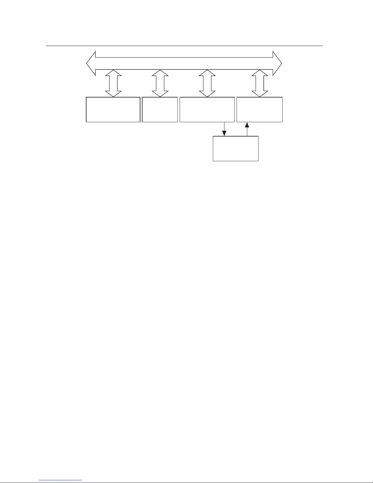
shown in Figure 1-1; however, the devices logically appear to be on the same bus, as shown in
Figure 1-2.
Figure 1-1. Typical GPIB-120B Expansion System (Physical Configuration)
GPIB-120BGPIB GPIB
Computer
(Controller, Talker,
and Listener)
Printer
(Listener)
Multimeter
(Talker and Listener)
Unit Under Test
Signal Generator
(Listener)
© National Instruments | 1-1
Page 10
Chapter 1 Introduction
Figure 1-2. Typical GPIB-120B Expansion System (Logical Configuration)
GPIB
Computer
(Controller, Talker,
and Listener)
Printer
(Listener)
Multimeter
(Talker and Listener)
Unit Under Test
Signal Generator
(Listener)
With the GPIB-120B, you can overcome the following two configuration restrictions imposed
by the ANSI/IEEE Standard 488.1-1987:
• An electrical loading limit of 15 devices per contiguous bus.
• A cable length limit of 20 m total per contiguous bus or 2 m multiplied by the number of
devices on the bus, whichever is smaller.
With each GPIB-120B, you can add up to 14 additional devices to the bus. The GPIB-120B
appears as a device load on each side of the expansion; therefore, one GPIB-120B increases the
maximum load limit from 15 devices to 28 devices. The cable length limit for the system is also
increased an additional 4 m to 20 m, depending on the number of devices on that side of the
expansion.
All signal expansion is bidirectional, meaning that Controllers, Talkers, and Listeners can be on
either side of the expander. The GPIB-120B light-emitting diodes (LEDs) indicate the location
of the System Controller, Active Controller, and Source Handshaker, with respect to the two
sides of the expansion.
Because the GPIB-120B is a functionally transparent expander, the same GPIB communications
and control programs that work with an unexpanded system can work unmodified with an
expanded system.
1-2 | ni.com
Page 11
GPIB-120B User Manual
What You Need to Get Started
* GPIB-120B
* 10 –18 VDC 9 W power supply
* Standard GPIB cables to connect both sides of the GPIB-120B to buses on either side
Optional Equipment
Contact National Instruments to order any of the following optional equipment.
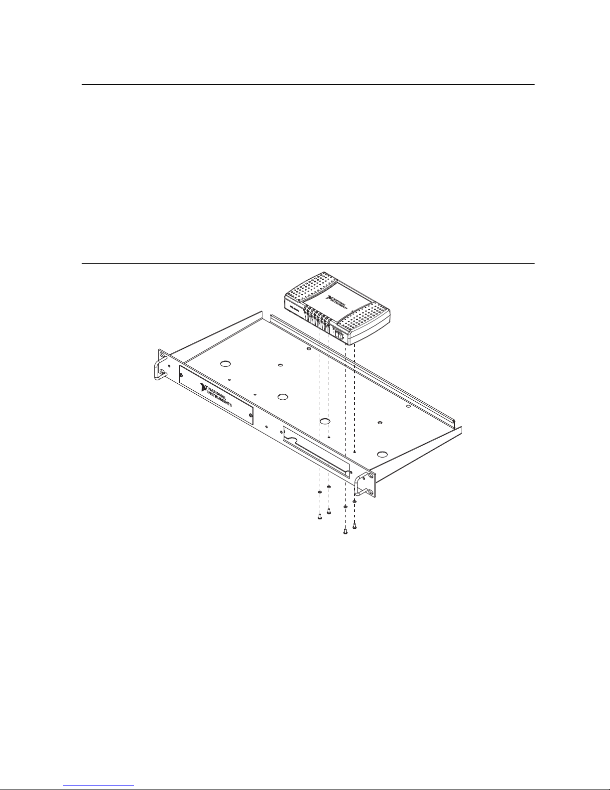
• Rack-mount kit (part number 194906-01, shown in Figure 1-3)
Figure 1-3. Rack Mount Kit
© National Instruments | 1-3
Page 12

Chapter 1 Introduction
• DIN rail mount kit (part number 779689-01, shown in Figure 1-4)
Figure 1-4. DIN Rail Mount Kit
• Shielded GPIB cables
1
– Type X2 double-shielded GPIB cables (1 m, 2 m, or 4 m)
Unpacking Your GPIB-120B
Follow these steps when unpacking your GPIB-120B.
1. Verify that the package you received contains the following:
• GPIB-120B Isolator/Expander
• 12 VDC power supply
• Power cord appropriate for your location
2. Inspect the shipping container and contents for damage. If the container is damaged, and
the damage appears to have been caused in shipment, file a claim with the carrier. If the
equipment is damaged, do not attempt to operate it. Contact National Instruments for
instructions. Retain the shipping material for possible inspection by carrier or reshipment
of the equipment.
3. Verify that the voltage you will be using is in the input range of your power adapter. The
GPIB-120B ships with a power adapter capable of working with an input AC voltage
between 100 V and 240 V. This adapter provides 12 VDC to the GPIB-120B. This adapter
can be replaced as long as the replacement provides the GPIB-120B with a DC voltage
between 10 VDC and 18 VDC and has appropriate safety certification marks for country of
use. Refer to Appendix C, Specifications, for more information.
1
To meet FCC emission limits for this Class A device, you must use a shielded GPIB cable. Operating this
equipment with a nonshielded cable may cause interference to radio and television reception in
commercial areas.
1-4 | ni.com
Page 13

2
Hardware Overview
This chapter describes your GPIB isolator/expander.
GPIB-120B LEDs
The GPIB-120B has seven light-emitting diodes (LEDs). The POWER LED on the left side of
the isolator/expander is lit whenever you power on the GPIB-120B.
For each bus, an LED indicates the status of the System Controller, Active Controller, or Source
Handshake state, as shown in Figure 2-1. LEDs associated with Bus A are green, while those
associated with Bus B are amber.
Figure 2-1. Front View GPIB-120B
PWR SC AC SH SC AC SH
GPIB-120B
Isolator / Expander
I0
Power On (PWR)
When you power on the GPIB-120B, all circuitry is cleared to an initialized state. The
isolation/expansion system is fully operational when you power on the GPIB-120B and your
instruments are connected. Where there is GPIB activity, keep at least two-thirds of the devices
on both buses powered on.
System Controller Detection (SC)
After you power on, Bus A and Bus B System Controller states are false. If a GPIB device on
Bus A asserts IFC or REN, the Bus A System Controller state becomes true, and the Bus B
System Controller state becomes false.
If a GPIB device on Bus B asserts IFC or REN, the Bus B System Controller state becomes true
and the Bus A System Controller state becomes false.
Active Controller Detection (AC)
After you power on, Bus A and Bus B Active Controller states are false. If a GPIB device on
Bus A asserts ATN, the Bus A Active Controller state becomes true and the Bus B Active
Controller state becomes false.
© National Instruments | 2-1
Page 14

Chapter 2 Hardware Overview
If a GPIB device on Bus B asserts ATN, the Bus B Active Controller state becomes true and the
Bus A Active Controller state becomes false.
Source Handshake Detection (SH)
A device is considered a source handshaker if it is an active Controller sourcing command bytes
or if it is a Talker sourcing data bytes.
After you power on, Bus A and Bus B Source Handshake states are false.
If a GPIB device on Bus A asserts DAV, the Bus A Source Handshake state becomes true and
the Bus B Source Handshake state becomes false.
If a GPIB device on Bus B asserts DAV, the Bus B Source Handshake state becomes true and the
Bus A Source Handshake state becomes false.
Data Transfer Modes
The GPIB-120B isolator/expander has two data transfer modes—unbuffered mode and buffered
mode. The data transfer mode determines how data is transmitted across the expansion. The
switch on the back of the GPIB-120B sets the GPIB isolator/expander operation mode. The
default switch setting is for unbuffered transfer mode.
Selecting a Data Transfer Mode
To select a data transfer mode, refer to the following descriptions of each mode.
Unbuffered Mode
In unbuffered mode, each data byte is transmitted using the GPIB double-interlocked
handshaking protocol. For long data streams, transfers are slower than transfers using buffered
mode. However, the GPIB isolator/expander is transparent in unbuffered mode.
Buffered Mode
In buffered mode, the GPIB isolator/expander uses FIFO (first-in-first-out) buffers to buffer data
between the remote and local sides of the isolation barrier. For long data streams, the data
throughput is much higher than with unbuffered mode.
However, a few applications may not operate properly in buffered mode. For example, a GPIB
device on the local side of the isolator/expander is addressed to talk, another device on the
remote side is addressed to listen. When the Talker sources data bytes, the GPIB
isolator/expander accepts the data bytes and stores them in a FIFO buffer. At the same time, the
GPIB isolator/expander reads data from the FIFO buffer and sources data bytes to the Listener.
If the FIFO buffer contains data, the number of bytes sourced by the Talker differs from the
number of bytes accepted by the Listener. Therefore, there could be situations in which the talker
will assume the listener has accepted data which the listener has not yet received because it is
2-2 | ni.com
Page 15

GPIB-120B User Manual
ON OFF
BUFFERED
still in the FIFO buffer. If this situation is unacceptable for your application, you must use
unbuffered mode, in which the 3-wire interlocked behavior of GPIB is maintained.
Buffered mode applies only to data transfers. GPIB command bytes are not stored in the FIFO
buffers; they are transmitted using the GPIB double-interlocked handshaking protocol.
Setting the Data Transfer Mode
To use buffered mode, set the switch to the ON position, as shown in Figure 2-2. To use
unbuffered mode, set the switch to the OFF position.
Figure 2-2. Switch Setting for Buffered Mode
Note The switch to select buffered or unbuffered mode is recessed to avoid
unintentional toggling during operation of the GPIB-120B. Flipping the switch may
require a flathead screwdriver or similar tool.
Verify that the switch on your GPIB isolator/expander is in the desired position before powering
on the unit.
Data Direction Control
Bus B sends the data lines to Bus A if the Bus B Source Handshake state is true or if a Controller
on Bus A is conducting a parallel poll.
Bus A sends the data lines to Bus B if the Bus A Source Handshake state is true or if a Controller
on Bus B is conducting a parallel poll.
Parallel Poll Detection
Controllers can conduct parallel polls on Bus A or Bus B, and devices on both Bus A and Bus B
can respond to parallel polls.
If a Controller on Bus A conducts a parallel poll, the parallel poll detection circuitry on side B
conducts a parallel poll on Bus B. The parallel poll result is driven on the data lines of Bus A.
If a Controller on Bus B conducts a parallel poll, the parallel poll detection circuitry on side A
conducts a parallel poll on Bus A. The parallel poll result is driven on the data lines of Bus B.
Refer to the Parallel Poll Operation section in this chapter for important information about
conducting parallel polls with the GPIB-120B.
© National Instruments | 2-3
Page 16

Chapter 2 Hardware Overview
Parallel Poll Operation
According to IEEE 488, devices must respond to a parallel poll within 200 ns after the
Controller-In-Charge (CIC) asserts the Identify (IDY) message—Attention (ATN) and End or
Identify (EOI). The CIC waits at least 2 µs before reading the Parallel Poll Response (PPR). In
some cases, a remote device on an expanded system cannot respond to parallel polls this quickly
because of propagation delays across the expander and the longer cables.
When the GPIB-120B notices that a GPIB controller is conducting a parallel poll, it sends a
message to the secondary side to initiate a parallel poll. The parallel poll on the secondary side
is of the same duration as the poll on the primary side, but delayed by the time it takes to get the
message to the secondary side. In the GPIB-120B this time is approximately 400 ns. When the
poll on the primary side finishes, a message is sent to finish it on the secondary side, where the
poll finishes about 400 ns later. Therefore, if the secondary side of the GPIB-120B waited until
the end of its parallel poll to send the result of the poll to the primary side, it would be after the
primary side poll has ended. Thus the controller would miss the responses of the devices on the
secondary side.
To solve this problem, the secondary side of the GPIB-120B samples the state of the bus every
600 ns during parallel polls and sends that data back to the primary side. Therefore, taking the
start of the poll on the primary side as time 0, the state of the secondary bus is sent to the primary
side at times 600 ns, 1200 ns, 1800 ns and so on, and again when the poll actually ends.
For slow devices or topologies in which a device on the secondary bus responds to the parallel
poll after the last data packet was sent to the primary side, the controller would miss the response
from this device. If you encounter this situation, you must configure your controller to conduct
parallel polls longer than 2 µs.
2-4 | ni.com
Page 17

3
Configuring and Using
Your Hardware
This chapter describes how to configure and use your GPIB-120B.
Connecting the GPIB-120B
To connect the GPIB-120B, follow the steps below.
1. Make sure that the power switch on the isolator/expander is in the off (0) position.
2. Plug the utility power cord of your 12 VDC power supply into an acceptable electrical
outlet (100-240 VAC). Plug the other end of the power cord into the power supply.
Connect the 12 VDC output of the power supply into the GPIB-120B rear panel.
3. Link your GPIB instrument(s), board(s), and other device(s) to the GPIB-120B with
appropriate cables.
4. Verify that the switch is in the data transfer mode required for your application. Refer to the
Setting the Data Transfer Mode section in Chapter 2, Hardware Overview.
5. Move the power switch to the on (1) position.
© National Instruments | 3-1
Page 18

A
GPIB Basics
This appendix describes the basic concepts of GPIB, including its physical and electrical
characteristics, and configuration requirements.
The ANSI/IEEE Standard 488.1-1987, also known as General Purpose Interface Bus (GPIB),
describes a standard interface for communication between instruments and controllers from
various vendors. It contains information about electrical, mechanical, and functional
specifications. GPIB is a digital, 8-bit parallel communications interface with data transfer rates
of 1 Mbyte/s and higher, using a three-wire handshake. The bus supports one System Controller,
usually a computer, and up to 14 additional instruments. The ANSI/IEEE Standard 488.2-1992
extends IEEE 488.1 by defining a bus communication protocol, a common set of data codes and
formats, and a generic set of common device commands.
Types of Messages
Interconnected GPIB devices communicate by passing messages through the interface system,
including device-dependent messages and interface messages.
• Device-dependent messages, also called data or data messages, contain device-specific
information, such as programming instructions, measurement results, machine status, and
data files.
• Interface messages, also called commands or command messages, manage the bus itself.
Interface messages initialize the bus, address and unaddress devices, and set device modes
for remote or local programming.
The term command as used here does not refer to device instructions, which are also called
commands. Those device-specific instructions are data messages.
Talkers, Listeners, and Controllers
GPIB devices can be Talkers, Listeners, or Controllers. A Talker sends out data messages.
Listeners receive data messages. The Controller, usually a computer, manages the flow of
information on the bus. It defines the communication links and sends GPIB commands to
devices.
Some devices can play more than one role. A digital voltmeter, for example, can be a Talker and
a Listener. If your system has a National Instruments GPIB interface and software installed, it
can function as a Talker, Listener, and Controller.
© National Instruments | A-1
Page 19

Appendix A GPIB Basics
The GPIB is like a typical computer bus, except that the typical computer has circuit cards
interconnected via a backplane bus, whereas the GPIB has standalone devices interconnected via
a cable bus.
The role of the GPIB Controller is similar to the role of the CPU of a computer, but a better
analogy is to the switching center of a city telephone system. The switching center (Controller)
monitors the communications network (GPIB). When the center (Controller) notices that a party
(device) wants to make a call (send a data message), it connects the caller (Talker) to the receiver
(Listener).
The Controller addresses a Talker and a Listener before the Talker can send its message to the
Listener. After the message is transmitted, the Controller may unaddress both devices.
Some bus configurations do not require a Controller. For example, one device may always be a
Talker (called a Talk-only device) and there may be one or more Listen-only devices.
A Controller is necessary when the active or addressed Talker or Listener must be changed. The
Controller function is usually handled by a computer.
With the GPIB interface board and its software your personal computer plays all three roles.
• Controller—to manage the GPIB
• Talker—to send data
• Listener—to receive data
Controller-In-Charge and System Controller
You can have multiple Controllers on the GPIB, but only one Controller at a time can be the
active Controller, or Controller-In-Charge (CIC). The CIC can be either active or inactive
(standby). Control can pass from the current CIC to an idle Controller, but only the System
Controller, usually a GPIB interface, can make itself the CIC.
GPIB Signals and Lines
Devices on the bus communicate by sending messages. Signals and lines transfer these messages
across the GPIB interface, which consists of 16 signal lines and 8 ground return (shield drain)
lines. The 16 signal lines are discussed in the following sections.
Data Lines
Eight data lines, DIO1 through DIO8, carry both data and command messages.
Handshake Lines
Three hardware handshake lines asynchronously control the transfer of message bytes between
devices. This process is a three-wire interlocked handshake, and it guarantees that devices send
A-2 | ni.com
Page 20

GPIB-120B User Manual
and receive message bytes on the data lines without transmission error. Table A-1 summarizes
the GPIB handshake lines.
Table A-1. GPIB Handshake Lines
Line Description
NRFD (not ready for data) Listening device is ready/not ready to receive a message byte.
Also used by the Talker to signal high-speed GPIB transfers.
NDAC (not data accepted) Listening device has/has not accepted a message byte.
DAV (data valid) Talking device indicates signals on data lines are stable (valid)
data.
Interface Management Lines
Five hardware lines manage the flow of information across the bus. Table A-2 summarizes the
GPIB interface management lines.
Table A-2. GPIB Interface Management Lines
Table Head Table Head
ATN (attention) Controller drives ATN true when it sends commands and false
when it sends data messages.
IFC (interface clear) System Controller drives the IFC line to initialize the bus and
make itself CIC.
REN (remote enable) System Controller drives the REN line to place devices in
remote or local program mode.
SRQ (service request) Any device can drive the SRQ line to asynchronously request
service from the Controller.
EOI (end or identify) Talker uses the EOI line to mark the end of a data message.
Controller uses the EOI line when it conducts a parallel poll.
Physical and Electrical Characteristics
Devices are usually connected with a cable assembly consisting of a shielded 24-conductor cable
with both a plug and receptacle connector at each end, as shown in Figure A-1. With this design,
you can link devices in a linear configuration, a star configuration, or a combination of the
two configurations. Figure A-2 shows the linear and star configurations.
© National Instruments | A-3
Page 21

Appendix A GPIB Basics
Figure A-1. GPIB Connector and the Signal Assignment
DIO1
DIO2
DIO3
DIO4
EOI
DAV
NRFD
NDAC
IFC
SRQ
ATN
SHIELD
10
11
12
1
13
2
14
3
15
4
16
5
17
6
18
7
19
8
20
9
21
22
23
24
DIO5
DIO6
DIO7
DIO8
REN
GND (TW PAIR W/DAV)
GND (TW PAIR W/NRFD)
GND (TW PAIR W/NDAC)
GND (TW PAIR W/IFC)
GND (TW PAIR W/SRQ)
GND (TW PAIR W/ATN)
SIGNAL GROUND
Figure A-2. Linear and Star System Configuration
Device A
Device B
Device C
a. Linear Configuration
A-4 | ni.com
Device DDevice A
Device CDevice B
b. Star Configuration
Page 22

GPIB-120B User Manual
The standard connector is the Amphenol or Cinch Series 57 Microribbon or Amp Champ type.
For special interconnection applications, use an adapter cable using a non-standard cable and/or
connector.
The GPIB uses negative logic with standard TTL (transistor-transistor logic) level. For example,
when DAV is true, it is a TTL low level ( 0.8 V), and when DAV is false, it is a TTL high level
( 2.0 V).
Configuration Requirements
To achieve the high data transfer rate that the GPIB was designed for, you must limit the number
of devices on the bus and the physical distance between devices. The following restrictions are
typical:
• A maximum separation of 4 m between any two devices and an average separation of 2 m
over the entire bus.
• A maximum total cable length of 20 m.
• A maximum of 15 devices connected to each bus, with at least two-thirds powered on.
For high-speed operation, the following restrictions apply:
• All devices in the system must be powered on.
• Cable lengths must be as short as possible with up to a maximum of 15 m of cable for each
system.
• There must be at least one equivalent device load per meter of cable.
To exceed these limitations, you can use a bus expander to increase the number of device loads.
You can order GPIB-120B bus expanders from National Instruments.
© National Instruments | A-5
Page 23

B
Multiline Interface Messages
This appendix lists the multiline interface messages and describes the mnemonics and messages
that correspond to the interface functions.
The multiline interface messages are commands defined by the IEEE 488 standard. The
messages are sent and received with ATN asserted. The interface functions include initializing
the bus, addressing and unaddressing devices, and setting device modes for local or remote
programming. For more information about these messages, refer to the ANSI/IEEE Standard
488.1-1987, IEEE Standard Digital Interface for Programmable Instrumentation.
Table B-1. Multiline Interface Messages
Hex Dec ASCII Message Hex Dec ASCII Message
00 0 NUL — 20 32 SP MLA0
01 1 SOH GTL 21 33 ! MLA1
02 2 STX — 22 34 " MLA2
03 3 ETX — 23 35 # MLA3
04 4 EOT SDC 24 36 $ MLA4
05 5 ENQ PPC 25 37 % MLA5
06 6 ACK — 26 38 & MLA6
07 7 BEL — 27 39 ' MLA7
08 8 BS GET 28 40 ( MLA8
09 9 HT TCT 29 41 ) MLA9
0A 10 LF — 2A 42 * MLA10
0B 11 VT — 2B 43 + MLA11
0C 12 FF — 2C 44 , MLA12
0D 13 CR — 2D 45 - MLA13
0E 14 SO — 2E 46 . MLA14
0F 15 SI — 2F 47 / MLA15
10 16 DLE — 30 48 0 MLA16
11 17 DC1 LLO 31 49 1 MLA17
© National Instruments | B-1
Page 24

Appendix B Multiline Interface Messages
Table B-1. Multiline Interface Messages
Hex Dec ASCII Message Hex Dec ASCII Message
12 18 DC2 — 32 50 2 MLA18
13 19 DC3 — 33 51 3 MLA19
14 20 DC4 DCL 34 52 4 MLA20
15 21 NAK PPU 35 53 5 MLA21
16 22 SYN — 36 54 6 MLA22
17 23 ETB — 37 55 7 MLA23
18 24 CAN SPE 38 56 8 MLA24
19 25 EM SPD 39 57 9 MLA25
1A 26 SUB — 3A 58 : MLA26
1B 27 ESC — 3B 59 ; MLA27
1C 28 FS — 3C 60 < MLA28
1D 29 GS — 3D 61 = MLA29
1E 30 RS — 3E 62 > MLA30
1F 31 US CFE 3F 63 ? UNL
40 64 @ MTA0 60 96 ` MSA0, PPE
41 65 A MTA1 61 97 a MSA1, PPE, CFG1
42 66 B MTA2 62 98 b MSA2, PPE, CFG2
43 67 C MTA3 63 99 c MSA3, PPE, CFG3
44 68 D MTA4 64 100 d MSA4, PPE, CFG4
45 69 E MTA5 65 101 e MSA5, PPE, CFG5
46 70 F MTA6 66 102 f MSA6, PPE, CFG6
47 71 G MTA7 67 103 g MSA7, PPE, CFG7
48 72 H MTA8 68 104 h MSA8, PPE, CFG8
49 73 I MTA9 69 105 i MSA9, PPE, CFG9
4A 74 J MTA10 6A 106 j MSA10, PPE, CFG10
4B 75 K MTA11 6B 107 k MSA11, PPE, CFG11
4C 76 L MTA12 6C 108 l MSA12, PPE, CFG12
B-2 | ni.com
Page 25

GPIB-120B User Manual
Table B-1. Multiline Interface Messages
Hex Dec ASCII Message Hex Dec ASCII Message
4D 77 M MTA13 6D 109 m MSA13, PPE, CFG13
4E 78 N MTA14 6E 110 n MSA14, PPE, CFG14
4F 79 O MTA15 6F 111 o MSA15, PPE, CFG15
50 80 P MTA16 70 112 p MSA16, PPD
51 81 Q MTA17 71 113 q MSA17, PPD
52 82 R MTA18 72 114 r MSA18, PPD
53 83 S MTA19 73 115 s MSA19, PPD
54 84 T MTA20 74 116 t MSA20, PPD
55 85 U MTA21 75 117 u MSA21, PPD
56 86 V MTA22 76 118 v MSA22, PPD
57 87 W MTA23 77 119 w MSA23, PPD
58 88 X MTA24 78 120 x MSA24, PPD
59 89 Y MTA25 79 121 y MSA25, PPD
5A 90 Z MTA26 7A 122 z MSA26, PPD
5B 91 [ MTA27 7B 123 { MSA27, PPD
5C 92 \ MTA28 7C 124 | MSA28, PPD
5D 93 ] MTA29 7D 125 } MSA29, PPD
5E 94 ^ MTA30 7E 126 ~ MSA30, PPD
5F 95 _ UNT 7F 127 DEL —
Multiline Interface Message Definitions
DCL Device Clear
GET Group Execute Trigger
GTL Go To Local
LLO Local Lockout
MLA My Listen Address
MSA My Secondary Address
MTA My Talk Address
PPC Parallel Poll Configure
P P E Parallel Poll Enable
P P U Parallel Poll Unconfigure
S D C Selected Device Clear
SPD Serial Poll Disable
S P E Serial Poll Enable
TCT Take Control
U N L Unlisten
U N T Untalk
P P D Parallel Poll Disable
© National Instruments | B-3
Page 26

C
Specifications
This appendix lists the GPIB-120B isolator/expander specifications and characteristics.
System Configuration
Loading per expansion Up to 14 additional devices (28 total devices in
the expansion system, not including the
GPIB-120B on the bus.)
Multiple expansions Permitted in any combination of star or linear
pattern
Performance Characteristics
Maximum transfer rate
Buffered mode > 1.25 Mbytes/s
Unbuffered mode > 450 kbytes/s
Interlocked IEEE 488 handshake Maintained across the expansion in unbuffered
mode
IEEE 488 capability identification codes
SH1 Complete Source Handshake
AH1 Complete Acceptor Handshake
T5, TE5 Complete Talker
L3, LE3 Complete Listener
SR1 Complete Service Request
RL1 Complete Remote Local
PP1, 2 Complete Parallel Poll
DC1 Complete Device Clear
DT1 Complete Device Trigger
© National Instruments | C-1
Page 27

Appendix C Specifications
C1–5 Complete Controller
E2 Tri-state GPIB driver
Operational Characteristics
Operating modes Buffered or unbuffered (interlocked) mode
Electrical Characteristics
GPIB-120B
Isolation
(Between ports and between each
port and the power supply) 2500 VDC dielectric withstand, 5 s max
Input voltage range 10-18 VDC
Current consumption @12 V 300 mA typical
500 mA maximum
Fuse rating and type F 2.2 A 125 V,
surface mount
12 VDC Power Supply
(Shipped with GPIB-120B)
Input voltage range 100-240 VAC
47-63 Hz
Environment
Maximum altitude 2,000 m (at 25 °C ambient temperature)
Pollution Degree 2
Indoor use only.
Operating Environment
Ambient temperature range 0 to 55 °C
C-2 | ni.com
(Tested in accordance with IEC 60068-2-1 and
IEC 60068-2-2.)
Page 28

GPIB-120B User Manual
Note For the GPIB-120B to operate correctly over the entire specified ambient
temperature range, stacking the product is not recommended.
Relative humidity range 10% to 90%, noncondensing
(Tested in accordance with IEC 60068-2-56.)
Storage Environment
Ambient temperature range -20 to 70 °C
(Tested in accordance with IEC 60068-2-1 and
IEC 60068-2-2.)
Relative humidity range 5% to 95%, noncondensing
(Tested in accordance with IEC 60068-2-56.)
Shock and Vibration
Operational shock 30 g peak, half-sine, 11 ms pulse
(Tested in accordance with IEC 60068-2-27.
Test profile developed in accordance with
MIL-PRF-28800F.)
Random vibration
Operating 5 to 500 Hz, 0.3 g
Nonoperating 5 to 500 Hz, 2.4 g
rms
rms
(Tested in accordance with IEC 60068-2-64.
Nonoperating test profile exceeds the
requirements of MIL-PRF-28800F, Class 3.)
Physical Characteristics
Overall dimensions 6.30 3.68 1.24 in.
(16.01 9.35 3.15 cm)
Case material PC-ABS plastic
Weight 8.64 oz (245 g)
GPIB cable Type X2 shielded
© National Instruments | C-3
Page 29

Appendix C Specifications
6.000 in.
(152.4 mm)
1.120 in.
(28.45 mm)
0.120 in.
(3.05 mm)
1.875 in.
(47.63 mm)
2.250 in.
(57.15 mm)
0.800 in.
(20.32 mm)
3.682 in.
(93.53 mm)
1.441 in.
(36.61 mm)
4 x 4– 40 Threaded Insert
Max Insertion 0.190 in. (4.82 mm)
0.152 in.
(3.86 mm)
0.152 in.
(3.86 mm)
0.637 in.
(16.17 mm)
1.795 in.
(45.59 mm)
GPIB-120B
Isolator / Expander
Figure C-1 shows the GPIB-120B dimensions.
Figure C-1. GPIB-120B Dimensions
Note The GPIB-120B has threaded inserts for mounting options.
C-4 | ni.com
Page 30

GPIB-120B User Manual
Safety
This product is designed to meet the requirements of the following standards of safety for
information technology equipment:
• IEC 61010-1, EN 61010-1
• UL 61010-1, CSA C22.2 No. 61010-1
Note For UL and other safety certifications, refer to the product label or the
Product Certifications and Declarations section.
Electromagnetic Compatibility
This product meets the requirements of the following EMC standards for electrical equipment
for measurement, control, and laboratory use:
• EN 61326-1 (IEC 61326-1): Class A emissions; Basic immunity
• EN 55011 (CISPR 11): Group 1, Class A emissions
• AS/NZS CISPR 11: Group 1, Class A emissions
• FCC 47 CFR Part 15B: Class A emissions
• ICES-001: Class A emissions
Note For the standards applied to assess the EMC of this product, refer to
the Product Certifications and Declarations section.
Note For EMC compliance, operate this device with shielded cabling.
CE Compliance
This product meets the essential requirements of applicable European Directives as follows:
• 2014/35/EU; Low-Voltage Directive (safety)
• 2014/30/EU; Electromagnetic Compatibility Directive (EMC)
Product Certifications and Declarations
Refer to the product Declaration of Conformity (DoC) for additional regulatory compliance
information. To obtain product certifications and the DoC for NI products, visit
ni.com/certification, search by model number or product line, and click the
appropriate link in the Certification column.
Environmental Management
NI is committed to designing and manufacturing products in an environmentally responsible
manner. NI recognizes that eliminating certain hazardous substances from our products is
beneficial to the environment and to NI customers.
© National Instruments | C-5
Page 31

Appendix C Specifications
⬉ᄤֵᙃѻક∵ᶧࠊㅵ⧚ࡲ⊩ ˄Ё
RoHS
˅
Ёᅶ᠋
National Instruments
ヺড়Ё⬉ᄤֵᙃѻકЁ䰤ࠊՓ⫼ᶤѯ᳝ᆇ⠽䋼ᣛҸ
(RoHS)
DŽ
݇Ѣ
National Instruments
Ё
RoHS
ড়㾘ᗻֵᙃˈ䇋ⱏᔩ
ni.com/environment/rohs_china
DŽ
(For information about China RoHS compliance, go to
ni.com/environment/rohs_china
.)
For additional environmental information, refer to the Minimize Our Environmental Impact web
page at ni.com/environment. This page contains the environmental regulations and
directives with which NI complies, as well as other environmental information not included in
this document.
Waste Electrical and Electronic Equipment (WEEE)
EU Customers At the end of the product life cycle, all NI products must be
disposed of according to local laws and regulations. For more information about how
to recycle NI products in your region, visit ni.com/environment/weee.
C-6 | ni.com
Page 32

D
NI Services
NI provides global services and support as part of our commitment to your success. Take
advantage of product services in addition to training and certification programs that meet your
needs during each phase of the application life cycle; from planning and development through
deployment and ongoing maintenance.
To get started, register your product at
As a registered NI product user, you are entitled to the following benefits:
• Access to applicable product services.
• Easier product management with an online account.
• Receive critical part notifications, software updates, and service expirations.
Log in to your MyNI user profile to get personalized access to your services.
ni.com/myproducts.
Services and Resources
• Maintenance and Hardware Services—NI helps you identify your systems’ accuracy and
reliability requirements and provides warranty, sparing, and calibration services to help you
maintain accuracy and minimize downtime over the life of your system. Vis it
services
– Warranty and Repair—All NI hardware features a one-year standard warranty that
is extendable up to five years. NI offers repair services performed in a timely manner
by highly trained factory technicians using only original parts at an NI service center.
– Calibration—Through regular calibration, you can quantify and improve the
measurement performance of an instrument. NI provides state-of-the-art calibration
services. If your product supports calibration, you can obtain the calibration certificate
for your product at ni.com/calibration.
for more information.
ni.com/
• System Integration—If you have time constraints, limited in-house technical resources, or
other project challenges, National Instruments Alliance Partner members can help. To learn
more, call your local NI office or visit ni.com/alliance.
© National Instruments | D-1
Page 33

Appendix D NI Services
• Training and Certification—The NI training and certification program is the most
effective way to increase application development proficiency and productivity. Visit
ni.com/training for more information.
– The Skills Guide assists you in identifying the proficiency requirements of your
current application and gives you options for obtaining those skills consistent with
your time and budget constraints and personal learning preferences. Visit ni.com/
skills-guide
to see these custom paths.
– NI offers courses in several languages and formats including instructor-led classes at
facilities worldwide, courses on-site at your facility, and online courses to serve your
individual needs.
• Technical Support—Support at ni.com/support includes the following resources:
– Self-Help Technical Resources—Visit
ni.com/support for software drivers and
updates, a searchable KnowledgeBase, product manuals, step-by-step troubleshooting
wizards, thousands of example programs, tutorials, application notes, instrument
drivers, and so on. Registered users also receive access to the NI Discussion Forums
ni.com/forums. NI Applications Engineers make sure every question submitted
at
online receives an answer.
– Software Support Service Membership—The Standard Service Program (SSP) is a
renewable one-year subscription included with almost every NI software product,
including NI Developer Suite. This program entitles members to direct access to
NI Applications Engineers through phone and email for one-to-one technical support,
as well as exclusive access to online training modules at
self-paced-training
. NI also offers flexible extended contract options that
ni.com/
guarantee your SSP benefits are available without interruption for as long as you need
them. Visit ni.com/ssp for more information.
• Declaration of Conformity (DoC)—A DoC is our claim of compliance with the Council
of the European Communities using the manufacturer’s declaration of conformity. This
system affords the user protection for electromagnetic compatibility (EMC) and product
safety. You can obtain the DoC for your product by visiting
ni.com/certification.
For information about other technical support options in your area, visit ni.com/services,
or contact your local office at ni.com/contact.
You also can visit the Worldwide Offices section of
office websites, which provide up-to-date contact information, support phone numbers, email
addresses, and current events.
D-2 | ni.com
ni.com/niglobal to access the branch
Page 34

Index
A
active controller detection, 2-2
C
CE compliance specifications, C-5
configuring
data transfer modes, 2-2
buffered, 2-2
setting, 2-3
switch setting, buffered (figure),
2-3
unbuffered, 2-2
hardware, 3-1
parallel poll response modes, 2-4
linear and star system (figure), A-5
requirements, A-5
system configuration specifications, C-1
connector and signal assignment (figure), A-4
controller-in-charge and system controller,
A-2
controllers, A-1
D
data direction control, 2-3
data transfer modes, 2-2
buffered, 2-2
setting, 2-3
switch setting, buffered (figure), 2-3
unbuffered, 2-2
description of GPIB-120B, 1-1
DIN rail mount kit (figure), 1-4
documentation
related documentation, ix
E
electrical characteristics, C-2
electromagnetic compatibility, C-5
environmental management specifications,
C-5
equipment, optional, 1-3
extension system, typical
logical configuration (figure), 1-2
physical configuration (figure), 1-2
G
getting started, 1-3
GPIB basics, A-1
configuration requirements, A-5
connector and signal assignment
(figure), A-4
controller-in-charge and system
controller, A-2
GPIB signals and lines
data lines, A-2
handshake lines (table), A-3
interface management lines (table),
A-3
linear and star system configuration
(figure), A-5
physical and electrical characteristics,
A-3
talkers, listeners, and controllers, A-1
types of messages, A-1
GPIB signals and lines, A-2
GPIB-120B
connecting, 3-1
description of, 1-1
H
handshake lines (table), A-3
hardware
configuring, 3-1
parallel poll response modes, 2-4
data transfer modes, 2-2
buffered, 2-2
setting, 2-3
switch setting, buffered (figure),
2-3
unbuffered, 2-2
overview, 2-1
© National Instruments | I-1
Page 35

Index
I
interface management lines (table), A-3
interface messages, multiline, B-1
table, B-1
L
LEDs
active controller detection, 2-2
data direction control, 2-3
meanings of colors, 2-1
parallel poll detection, 2-3
power on, 2-1
source handshake detection, 2-2
system controller detection, 2-1
linear and star system configuration (figure),
A-5
listeners, A-1
M
multiline interface messages, B-1
table, B-1
S
safety specifications, C-5
source handshake detection, 2-2
specifications
CE compliance, C-5
electrical characteristics, C-2
electromagnetic compatibility, C-5
environmental management, C-5
operational characteristics, C-2
performance characteristics, C-1
physical characteristics, C-3
safety, C-5
system configuration, C-1
Waste Electrical and Electronic
Equipment (WEEE), C-6
switch setting, buffered (figure), 2-3
system configuration, C-1
system controller detection, 2-1
T
talkers, A-1
types of messages, A-1
O
operational characteristics, C-2
optional equipment, 1-3
overview, hardware, 2-1
P
parallel poll detection, 2-3
parallel poll response modes, 2-4
performance characteristics, C-1
physical and electrical characteristics, A-3
physical characteristics, C-3
power on, 2-1
product certifications and declarations, C-5
R
rack mount kit (figure), 1-3
related documentation, ix
U
unpacking, 1-4
W
Waste Electrical and Electronic Equipment
(WEEE) specifications, C-6
I-2 | ni.com
 Loading...