

Page 1

OPERATING INSTRUCTIONS
FP-PS-4
FieldPoint Power Supply
These operating instructions describe the installation, features, and
characteristics of the FP-PS-4.
Features
The FP-PS-4 is a FieldPoint power supply module with the
following features:
• 24 VDC output
• Convenient DIN rail mounting or optional panel mounting
• Universal AC power input: 90 to 264 VAC, 47 to 63 Hz
• Modular FieldPoint form factor for easy integration with other
FieldPoint modules
• 15 W output for 0 to 50 °C operation
Installation
You can mount your FieldPoint system either to a DIN rail or
directly on a panel. The following sections give instructions for
both mounting methods.
Mounting Your FP-PS-4 on a DIN Rail
The FP-PS-4 power supply module has a simple rail clip for
reliable mounting onto a standard 35 mm DIN rail. Follow these
steps to mount the module on a DIN rail.
FieldPoint™, National Instruments™, NI™, and ni.com™ aretrademarks of National Instruments Corporation.
Product and company names mentioned herein are trademarks or trade names of their respective companies.
323179A-01
©
2001 National Instruments Corp. All rights reserved. November 2001
Page 2

1. Use a flat-bladed screwdriver to unlock the DIN rail clip, as
showninFigure1.
1 2
1 Rail clip locked 2 Rail clip unlocked
Figure 1. Unlocking the Rail Clip
2. Attach the lip on the rear of the FP-PS-4 onto the top of a
35 mm DIN rail and press it down onto the DIN rail, as shown
in Figure 2.
N
AT I
ONA
I
N
S
L
TRUM
E
NT
S
24VDC Power Supply
FP-PS-4
INPUT
100-240V
47-63Hz
0.6AMax
OUTPUT
!
24V @0.6A Max
Figure 2. Attaching the Module to a DIN Rail
FP-PS-4 Operating Instructions 2 ni.com
Page 3
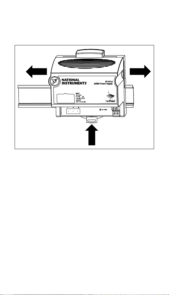
3. Slide the FP-PS-4 to the desired position along the DIN rail.
For maximum cooling, leave a 25 mm (1.0 in.) space between
the FP-PS-4 and other devices on your DIN rail. After it is in
position, lock it to the DIN rail by pushing the rail clip to the
locked position, as shown in Figure 3.
Figure 3. Positioning and Locking Your Module
© National Instruments Corp. 3 FP-PS-4 Operating Instructions
Page 4
Mounting Your FP-PS-4 on a Panel
Follow these steps to install the optional FieldPoint network panel
mount accessory and mount the FP-PS-4 power supply module to
a panel. You can order the panel mount accessory, part number
777609-01, from National Instruments.
1. Use a flat-bladed screwdriver to unlock the rail clip, as shown
in Figure 1.
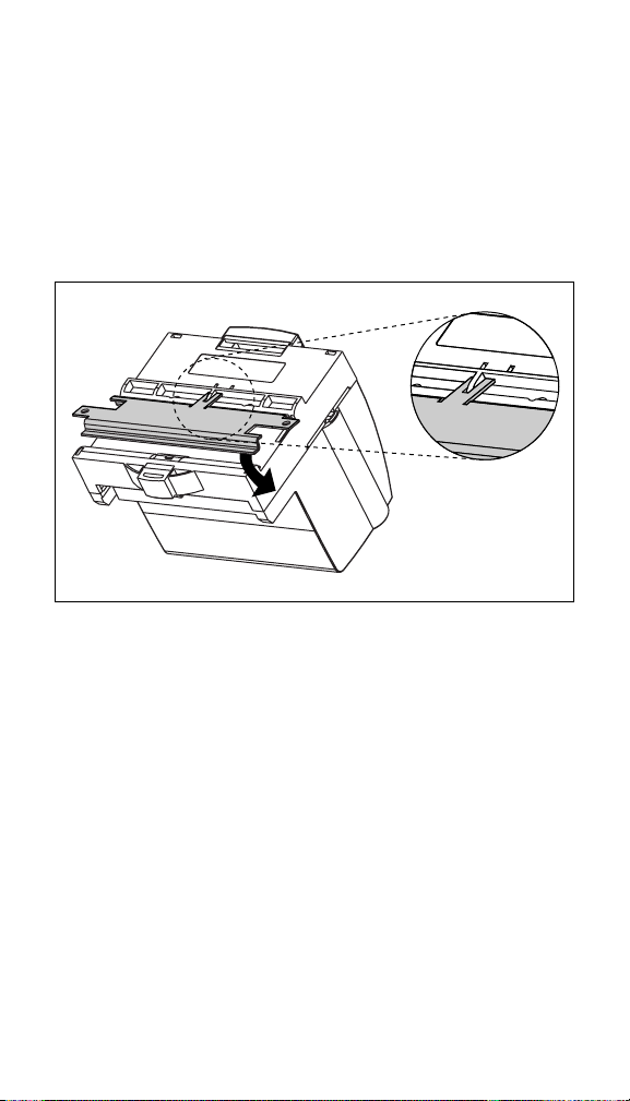
2. Attach the panel mount accessory to the module, as shown in
Figure 4.
Figure 4. Installing the Panel Mount Accessory
3. Lock the panel mount accessory into place by pushing the rail
clip to the locked position.
FP-PS-4 Operating Instructions 4 ni.com
Page 5

4. Mount the FP-PS-4 to your panel with the panel mount
accessory, as shown in Figure 5. The installation guide that
comes with the panel mount accessory includes a template that
you can use to drill pilot holes for mounting FieldPoint
modules. For maximum cooling, leave a 25 mm (1.0 in.) space
between the FP-PS-4 and other devices.
Figure 5. Connecting Your FP-PS-4 to the Panel
Connecting Power to Your
FieldPoint System
Caution
FieldPoint system, make sure the power cord is not
pluggedintoanelectricaloutlet.
Each FP-PS-4 provides a 24 VDC output. You decide the number
of FP-PS-4 modules you need in your bank based upon the specific
power and isolation requirements. The total power of all of the
FieldPoint modules and other devices connected to an FP-PS-4
cannot exceed the specified output for the temperature range at
which you are using FP-PS-4. For FieldPoint power requirement
details, refer to the operating instructions for your particular I/O
modules. Decide how you want to power your FieldPoint bank
based on the power requirements of your bank and your isolation
© National Instruments Corp. 5 FP-PS-4 Operating Instructions
Before you connect the FP-PS-4 to your
Page 6

needs. Select one or a combination of the methods to power the
signals of each of your I/O modules:
• The signals of the I/O module are powered by an FP-PS-4 that
is connected to only that I/O module.
• The signals of the I/O module share an FP-PS-4 with a
neighboring I/O module or network module. This is called
cascading power.
Caution
Cascading power from neighboring bases or
network modules defeats isolation between cascaded
modules.
Figure 6 shows a combination of the two ways to power the
FieldPoint bank.
FP-DO-400FP-RLY-420FP-AO-200FP-2000
FP-PS-4 Bank
V
1
16 V
15
31 32 C
CAUTION: Cascading
power defeats isolation.
32
C
17
18
Figure 6. Wiring Power to Your FieldPoint Bank
In Figure 6, the FP-PS-4 bank provides the power using both of the
methods mentioned previously. The FP-2000 and FP-AO-200 have
their own power supplies. Isolation is maintained because the
FP-AO-200 has its own power supply. The FP-RLY-420 and
FP-DO-400 share a power supply, which provides enough power,
but defeats isolation between the signals of those two modules.
FP-PS-4 Operating Instructions 6 ni.com
Page 7

Ensure that all the wiring is installed according to local codes and
regulations by qualified electrical personnel. Follow these steps to
connect the FP-PS-4 to your FieldPoint system.
1. Use a 16 to 26 AWG stranded wire to connect the FP-PS-4 to
your FieldPoint network module or I/O module. Connect the
positive wire to the V terminal and the negative wire to the
C terminal of the FP-PS-4.
2. Connect the other ends of the wires to the V and C terminals of
the FieldPoint network module or I/O module.
3. Ensure that the plug-in AC input terminal connector is plugged
into the input port on the FP-PS-4.
Be careful to install the correct conductor in the
Note
appropriate terminal. The color of the conductor wires
varies depending on North American versus international
standards as described in Figure 7. The wires are drawn
to scale according to the 7 mm (0.275 in.) strip length
requirement.
4
1
3
1 Line wire (black by North American standards; brown by international
standards)
2 Neutral wire (white by North American standards; blue by international
standards)
3 Ground wire (green by North American standards; green/yellow by
international standards)
4 Plug-in AC input terminal connector
Figure 7. Conductor Wire Color Standards for the Plug-in AC Input
Terminal Connector
LN
2
4. Connect the black or brown conductor into the line terminal
labeled L.
5. Connect the white or blue conductor into the neutral terminal
labeled N.
© National Instruments Corp. 7 FP-PS-4 Operating Instructions
Page 8

6. Connect the green or green/yellow conductor into the ground
terminal.
Caution
When you install the conductors, make sure that
the entire conductor is in the screw terminal and that there
are no loose strands outside of the terminal. Only install
one wire in each terminal.
Specifications
The following specifications are typical for a range of 0 to 60 °C,
unless otherwise noted.
Installation
Terminal wiring ................................ 16-26 AWG copper
conductor wire with 7 mm
(0.275 in.) strip length as
showninFigure8
7mm
Figure 8. ConductorWirewiththeCorrectStripLength(drawingistoscale)
Torque for screw terminals ...............0.5-0.6 Nm (4.4–5.3 in.-lbs)
Input Characteristics
Input voltage ..................................... 90–264 VAC
Frequency .........................................47–63 Hz, single phase
Maximum current consumption........ 0.6 A at 120 VAC, 60 Hz
Input protection................................. Nonreplaceable internal
AC f use
Output Characteristics
Output voltage ..................................24 VDC, nonadjusting
Nominal current (I
Nominal continuous power
0to50°C ................................... 15 W
50 to 60 °C .................................10 W
FP-PS-4 Operating Instructions 8 ni.com
)......................... 600 mA
N
Page 9

Overload protection .......................... Protected against short
circuits and output overload
Physical
Indicator............................................ Green DC POWER LED
Weight...............................................300 g (10.5 oz)
Environmental
FieldPoint modules are intended for indoor use only.
Operating temperature
15 W operation ...........................0 to 50 °C
10 W operation ...........................50 to 60 °C
Storage temperature .......................... –40 to +85 °C
Humidity ........................................... 10 to 90% RH,
noncondensing
Maximum altitude............................. 2,000 m
Pollution degree ................................2
Safety
Do not operate FieldPoint products in an explosive atmosphere or
where there may be flammable gases or fumes. If you need to
operate FieldPoint products in such an environment, the FieldPoint
products must be in a suitably rated enclosure. The FP-PS-4 meets
the requirements of the following standards for safety and
electrical equipment for measurement, control, and laboratory use:
• EN 61010-1:1993/A2:1995, IEC 61010-1:1990/A2:1995
• UL 3121-1:1998
• CAN/CSA C22.2 no. 1010.1:1992/A2:1997
Electromagnetic Compatibility
CE, C-Tick and FCC Part 15 (Class A) Compliant
Electrical emissions .......................... EN 55011 Class A at 10 m
FCC Part 15A above 1 GHz
Electrical immunity ..........................Evaluated to EN 61326:
For full EMC compliance, you must operate this
Note
device with shielded cabling. See the Declaration of
Conformity (DoC) for this product for any additional
© National Instruments Corp. 9 FP-PS-4 Operating Instructions
1997/A1: 1998, Table 1
Page 10

regulatory compliance information. To obtain the DoC
for this product, click Declaration of Conformity at
ni.com/hardref.nsf/
.
Mechanical Dimensions
Figure 9 shows the mechanical dimensions of the FP-PS-4.
Dimensions are given in millimeters [inches].
107.19 [4.22]
109.5
[4.31]
91.44 [3.60]
Figure 9. Mechanical Dimensions
FP-PS-4 Operating Instructions 10 ni.com
Page 11

Where to Go for Support
For more information about setting up your FieldPoint system,
refer to these National Instruments documents:
• Your FieldPoint network module user manual
• Your other FieldPoint I/O module operating instructions
• Your FieldPoint terminal base operating instructions
Go to
ni.com/support
and troubleshooting information.
For telephone support in the United States, create your service
request at
ni.com/ask
512 795 8248. For telephone support outside the United States,
contact your local branch office:
Australia 03 9879 5166, Austria 0662 45 79 90 0,
Belgium 02 757 00 20, Brazil 011 284 5011,
Canada (Calgary) 403 274 9391, Canada (Montreal) 514 288 5722,
Canada (Ottawa) 613 233 5949, Canada (Québec) 514 694 8521,
Canada (Toronto) 905 785 0085, China (Shanghai) 021 6555 7838,
China (ShenZhen) 0755 3904939, Czech Republic 02 2423 5774,
Denmark 45 76 26 00, Finland 09 725 725 11, France 01 48 14 24 24,
Germany 089 741 31 30, Greece 30 1 42 96 427,
Hong Kong 2645 3186, India 91805275406,
Israel 03 6120092, Italy 02 413091, Japan 03 5472 2970,
Korea 02 596 7456, Malaysia 603 9596711,
Mexico 001 800 010 0793, Netherlands 0348 433466,
New Zealand 09 914 0488, Norway 32 27 73 00,
Poland 0 22 528 94 06, Portugal 351 1 726 9011,
Russia 095 2387139, Singapore 2265886, Slovenia 386 3 425 4200,
South Africa 11 805 8197, Spain 91 640 0085,
Sweden 08 587 895 00, Switzerland 056 200 51 51,
Taiwan 02 2528 7227, United Kingdom 01635 523545
for the most current manuals, examples,
and follow the calling instructions or dial
© National Instruments Corp. 11 FP-PS-4 Operating Instructions
 Loading...