

Page 1

FieldPoint Operating Instructions
FP-CTR-502 and
cFP-CTR-502
Eight-Channel, 16-Bit Counter Module
These operating instructions describe how to install and use the
National Instruments FP-CTR-502 and cFP-CTR-502 counter
modules (referred to inclusively as the [c]FP-CTR-502). For
information about configuring and accessing the [c]FP-CTR-502
over a network, refer to the user manual for the FieldPoint network
module you are using.
Features
The [c]FP-CTR-502 is a FieldPoint counter module with the
following features:
• Eight 16-bit counters with individual count-input terminals
• Four gate-input channels configurable as either gates or digital
inputs
• Four output channels configurable as either generic digital
outputs or associated outputs for the count-input channels
• 5–30 VDC sourcing inputs and sinking outputs, compatible
with TTL devices and other 5, 12, and 24 VDC devices
• Internal frequency references of 1 kHz and 32 kHz
• Internally cascadable counters
• Software-enabled 50 kHz or 200 Hz lowpass filter on
count-input channels
• On/Off LED indicators
• 2,300 V
• Hot swappable
transient overvoltage protection
rms
FieldPoint™, National Instruments™, NI™, and ni.com™ are trademarks of National Instruments Corporation.
Product and company names mentioned herein are trademarks or trade names of their respective companies.
For patents covering National Instruments products, refer to the appropriate location: Help»Patents in your software,
the
patents.txt file on your CD, or ni.com/patents.
323324B-01 June 2003
© 2002–2003 National Instruments Corp. All rights reserved.
Page 2

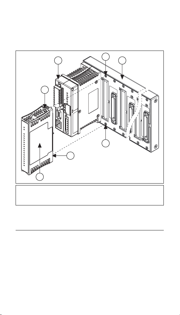
Installing the FP-CTR-502
The FP-CTR-502 mounts on a FieldPoint terminal base (FP-TB-x),
which provides operating power to the module. Installing the
FP-CTR-502 onto a powered terminal base does not disrupt the
operation of the FieldPoint bank.
To install the FP-CTR-502, refer to Figure 1 and complete the
following steps:
1. Slide the terminal base key to either position X, used for any
module, or position 8, used for the FP-CTR-502 module.
2. Align the FP-CTR-502 alignment slots with the guide rails on
the terminal base.
3. Press firmly to seat the FP-CTR-502 on the terminal base.
When the module is firmly seated, the terminal base latch locks
it into place.
Key
Latch
Alignment
Slot
Guide Rails
Terminal BaseI/O Module
Figure 1. Installing the FP-CTR-502
Installing the cFP-CTR-502
The cFP-CTR-502 mounts on a Compact FieldPoint backplane
(cFP-BP-x), which provides operating power to the module.
Installing the cFP-CTR-502 onto a powered backplane does not
disrupt the operation of the FieldPoint bank.
To install the cFP-CTR-502, refer to Figure 2 and complete the
following steps:
1. Align the captive screws on the cFP-CTR-502 with the holes
on the backplane. The alignment keys on the cFP-CTR-502
prevent backward insertion.
FP-CTR-502 and cFP-CTR-502 2 ni.com
Page 3
2. Press firmly to seat the cFP-CTR-502 on the backplane.
3. Using a number 2 Phillips screwdriver with a shank of at least
64 mm (2.5 in.) length, tighten the captive screws to 1.1 N ⋅ m
(10 lb ⋅ in.) of torque. The nylon coating on the screws prevents
them from loosening.
3 5
2
2
1
1 cFP I/O Module
2 Captive Screws
3 cFP Controller
Figure 2. Installing the cFP-CTR-502
4
4
4 Screw Holes
5 cFP Backplane
Wiring the [c]FP-CTR-502
The FP-TB-x terminal base has connections for each FP-CTR-502
channel and for an external power supply to power the input
channels and field devices. The cFP-CB-x connector block
provides the same connections for the cFP-CTR-502. The V and
V
terminals are all internally connected, as are the C and COM
SUP
terminals.
© National Instruments Corp. 3 FP-CTR-502 and cFP-CTR-502
Page 4

Use a 5–30 VDC external power supply for the input channels.
The power supply must provide enough current to power all of the
input channels and all of the field devices on the output channels.
Connect the external power supply to multiple V and V
SUP
terminals and to multiple C and COM terminals as needed to
ensure that the maximum current through any terminal is 2 A
or less.
Install a 2 A maximum, fast-acting fuse between the external
power supply and the V or V
a 1 A maximum, fast-acting fuse suitable for the load at the V
terminal on each channel. Install
SUP
OUT
terminal. The detailed wiring diagrams in this document show
fuses where appropriate.
Table 1 lists the terminal assignments for the signals of each
channel. Terminal assignments are also listed on the side panel of
the cFP-CTR-502 and under the slide-in card on the front of the
FP-CTR-502.
Table 1. Terminal Assignments
Ter m i n a l Nu m b e rs
Channel Name
Count Input 0 1 17 18
Count Input 1 2 17 18
Count Input 2 3 19 20
Count Input 3 4 19 20
Count Input 4 5 21 22
Count Input 5 6 21 22
Count Input 6 7 23 24
Count Input 7 8 23 24
Gate 0 9 25 26
Gate 1 10 25 26
Gate 2 11 27 28
Gate 3 12 27 28
VIN or V
1
OUT
Count Inputs
Gate Inputs
2
V
SUP
COM
FP-CTR-502 and cFP-CTR-502 4 ni.com
Page 5

Table 1. Terminal Assignments (Continued)
Ter m i n a l Nu m b e rs
Channel Name
Output 0 13 29 30
Output 1 14 29 30
Output 2 15 31 32
Output 3 16 31 32
1
Install a 1 A maximum, fast-acting fuse on each V
2
Install a 2 A maximum, fast-acting fuse on each V and V
VIN or V
1
OUT
Outputs
2
V
SUP
OUT
COM
terminal.
terminal.
SUP
Inputs
Each input channel has one input terminal, VIN. Each channel also
has V
devices or provide additional connections to the external power
supply. You can connect the eight count-input channels and four
gate-input channels to devices with sinking outputs. The
[c]FP-CTR-502 has sourcing inputs, which means that the V
terminal provides a path to a voltage supply.
The [c]FP-CTR-502 input channels are optically isolated from
the rest of the FieldPoint bank and have current-limiting circuitry.
All the input channels are referenced to the V and V
In the ON state, an optoisolator is turned on between the positive
external supply voltage (V and V
When choosing your external devices and power supply, keep in
mind that the input-logic thresholds are defined by the power
supply as detailed in the Specifications section.
where V
When V
the channel is ON. Therefore, if you connect a 24 V power supply
to the [c]FP-CTR-502, an input channel registers an ON state when
and COM terminals that can supply power to field
SUP
) and the input (VIN).
SUP
V
is the threshold voltage for the channel
threshold
is the supply voltage, measured across V
V
SUP
and COM
has a value of 2–3 V
V
K
, the voltage across VIN and COM, is lower than V
IN
threshold
= V
SUP
– V
K
terminals.
SUP
SUP
IN
threshold
,
© National Instruments Corp. 5 FP-CTR-502 and cFP-CTR-502
Page 6
VIN is 21 V or lower, and an OFF state when VIN is 22 V or higher.
The channel state is indeterminate when V
and22V.
is between 21 V
IN
Ensure that the sinking-output devices have OFF state leakage
currents of less than 0.3 mA so they do not send false ON state
readings to the [c]FP-CTR-502.
Note Yo u must use the same ground for all of the input
and output channels on the [c]FP-CTR-502.
+–
5–30 VDC
External
2 A max
Power
Supply
VC
To next channel
Sinking-
Output
Device
V
SUP
V
COM
IN
Sourcing-
Input
Circuitry
[c]FP-CTR-502
Figure 3. Wiring a Count-Input or Gate-Input Channel to a
Sinking-Output Device
Outputs
Each output channel has one output terminal, V
also has V
and COM terminals that can supply power to field
SUP
devices.
The [c]FP-CTR-502 has sinking outputs, which means that V
provides a path to ground. You can connect the [c]FP-CTR-502
outputs to sourcing-input devices.
In the ON state, a transistor is turned on between the output (V
and common (C and COM). In the OFF state, this transistor is
turned off, allowing only a small leakage current to flow. Ensure
that the load on any output channel does not draw more than 1 A.
. Each channel
OUT
OUT
OUT
)
FP-CTR-502 and cFP-CTR-502 6 ni.com
Page 7
2 A max
+–
5–30 VDC
External
Power Supply
VC
Sinking-
Output
Circuitry
To next channel
[c]FP-CTR-502
V
SUP
V
OUT
COM
1 A max
Load
Figure 4. Wiring an Output Channel to a Sourcing-Input Device
If you connect a [c]FP-CTR-502 output to an externally powered
sourcing-input device, be aware that the voltage applied to the
V
terminal by the external device must not exceed the voltage
OUT
level of the power supply connected to the [c]FP-CTR-502.
V
SUP
+
V
To next channel
[c]FP-CTR-502
5–30 VDC
–
Power Supply
C
Sinking-
Output
Circuitry
External
V
SUP
V
OUT
COM
1 A max
Load
≤
V
SUP
External
Power Supply
+
–
Figure 5. Wiring an Output to an Externally Powered Sourcing-Input Device
© National Instruments Corp. 7 FP-CTR-502 and cFP-CTR-502
Page 8

Configuring Count-Input Channels
Channels 0–7 are count-input channels. In FieldPoint software,
you can configure each count-input channel to operate with
attributes and commands. In the Channel Configuration dialog
box, select attributes for each channel from the Attributes menu
and commands from the Commands menu. The following sections
describe the different attributes and commands you can select
when you are configuring the count-input channels. For more
information about using FieldPoint software, refer to the
FieldPoint software help file.
Terminal Count
To set the terminal count, enter a value from 0 to 65,535 in the
Value field. The default value is 65,535. When the count-input
channel exceeds its terminal count, the count resets to 0 and
triggers any outputs associated with it. For more information about
associating outputs with a count-input channel, refer to the
Configuring Output Channels section. The count-input channel
also sends a count trigger to the next count-input channel if that
channel is set to use the previous channel as the count source.
Channel Status
In FieldPoint software, the [c]FP-CTR-502 reports one of the
following statuses:
read
. The default channel status is Successful. If a count-input
channel exceeds the terminal count, the channel resets to 0 and
starts counting again, and the channel status changes to
since last read
Successful or Overflow since last
Overflow
.
Count Source
Select one of the following count sources from the Value menu:
External Count Input, Previous Channel, 1kHz Reference,
or 32 kHz Reference. Select External Count Input, 1 kHz
Reference, or 32 kHz Reference to configure the channel so that
it counts low-to-high (off-to-on or rising-edge) transitions of the
count source.
Select Previous Channel if you want the channel to count the
number of times that the previous count-input channel reaches
its terminal value and resets to 0. You can configure multiple
counters to operate as one large counter. You can slave Channel 1
FP-CTR-502 and cFP-CTR-502 8 ni.com
Page 9
to Channel 0, Channel 0 to Channel 7, Channel 7 to Channel 6,
and so on. If you select this option for all of the channels, no
counting occurs.
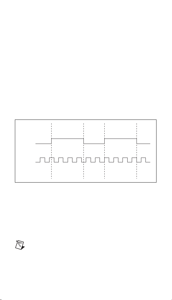
Gate Source
Select Gate Input 0–3 from the Value menu to associate a
gate-input channel with a count-input channel. If the count-input
channel uses one of the external gate inputs, counting is enabled
when the gate-input signal is high and is disabled when the signal
is low, as shown in Figure 6. The gate-input signal is high when the
channel is ON. The external device determines the high and low
intervals of the gate-input signal. If you do not associate a
gate-input channel with the count-input channel, select Always
Disabled or Always Enabled. Select Always Enabled if you want
the count-input channel to count at all times, even if there is
nothing wired to the gate input. Always Enabled is the default
value.
Gate
Input
Count
Input
001233334566
Figure 6. Gate Source Set to External Gate Input
Read Reset Mode
You can configure each count-input channel to reset each time the
FieldPoint network module reads it by selecting Reset on Read
from the Value menu. A read-initiated reset also resets any outputs
associated with the target channel. The default is Don’t Reset
On Read.
Note Read Reset mode is not intended to be used with
FieldPoint Ethernet network modules.
© National Instruments Corp. 9 FP-CTR-502 and cFP-CTR-502
Page 10

Noise Rejection
Each count-input channel has a software-enabled lowpass filter
that you can set to reject frequencies above 200 Hz or 50 kHz.
Select 200 Hz or 50 kHz from the Value menu to configure noise
rejection. The default is 50 kHz.
Control
You can set the Control command to increment or reset by selecting
Increment or Reset from the Action menu. The increment-control
command increases the count-input channel in value by one. The
reset-control command resets the count-input channel. The control
commands ignore the gate-source setting and gate-input state.
Configuring Gate-Input Channels
Channels 8–11 are gate-input channels. The only difference
between the input circuits of the gate-input channels and those of
the count-input channels is that the gate-input channels do not have
a programmable lowpass filter. The states of the gate inputs can
always be read as simple digital inputs on Channels 8–11.
You do not need to configure anything in software for the
gate-input channels.
Configuring Output Channels
Channels 12–15 are digital output channels. In the Channel
Configuration dialog box of FieldPoint software, you can select
attributes for each output channel from the Attributes menu. The
following sections describe the different attributes you can select
for output channels.
Output Source
You can configure each output channel to operate either as an
associated output for one of the eight count-input channels or as
a generic digital output. Select Counter Channel 0–7 from the
Value menu if you want the digital output channel to operate as an
output for a corresponding count-input channel. Select Discrete
Data from the Value menu if you want to use this channel as a
generic digital output. When you write data to an output channel,
you affect the output state only if you configure the Output Source
as Discrete Data.
FP-CTR-502 and cFP-CTR-502 10 ni.com
Page 11

Output Mode
For each output channel select one of the following output modes
from the Value menu: Toggle, Reset Off; Toggle, Reset On;
On Pulse; or Off Pulse. The output modes work only if you select
Counter Channel 0–7 for the Output Source. The following
sections describe the different output modes.
Toggle, Reset Off
In Toggle, Reset Off mode, the output channel starts low and goes
high when the terminal count is exceeded. The output channel
returns to low the next time the terminal count is exceeded or when
you send a reset command to the associated count-input channel.
In Figure 7, the terminal count is 4.
Count
Input
012340123401
Output
Figure 7. Output of a Channel Set to Toggle, Reset Off Mode
Toggle, Reset On
In Toggle, Reset On mode, the output channel starts high and goes
low when the terminal count is exceeded. The output channel
returns to high the next time the terminal count is exceeded or
when you send a reset command to the associated count-input
channel. In Figure 8, the terminal count is 4.
Count
Input
012340123401
Output
Figure 8. Output of a Channel Set to Toggle, Reset On Mode
© National Instruments Corp. 11 FP-CTR-502 and cFP-CTR-502
Page 12

On Pulse
In On Pulse mode, the output channel starts low and goes high
when the terminal count is exceeded. The output channel returns
to low after one count. In Figure 9, the terminal count is 4.
Count
Input
012340123401
Output
Figure 9. Output of a Channel Set to On Pulse Mode
Off Pulse
In Off Pulse mode, the output channel starts high and goes low
when the terminal count is exceeded. The output channel returns to
high after one count. In Figure 10, the terminal count is 4.
Count
Input
012340123401
Output
Figure 10. Output of a Channel Set to Off Pulse Mode
FP-CTR-502 and cFP-CTR-502 12 ni.com
Page 13

Application Note: Generating a Continuous Pulse Train
You can use two [c]FP-CTR-502 count-input channels and one
output channel to generate a continuous pulse train with a
controllable duty cycle and period. The first count-input channel
serves as a clock prescaler and divides the input clock by a fixed
value. This generates a slower clock for the second count-input
channel, which serves as the pulse counter. The pulse counter is the
output source for the output channel.
Figure 11 shows the components of a continuous pulse train.
Clock
Input
Prescaler
Counter
[c]FP-CTR-502
Internal
Connection
n
Figure 11. Continuous Pulse Train
Pulse
Counter
Pulse Output Terminal
Connection
n
+ 1
Internal
Output
Step 1. Set Up the Prescaler Counter
To set up the prescaler counter, complete the following steps:
1. If you do not need to scale the frequency of your clock input,
you can configure the pulse counter to use the clock input
directly instead of the prescaler counter. To set up the pulse
counter, skip to Step 2. Set Up the Pulse Counter.
2. Select two count-input channels and an output channel to use.
Select count-input channels that are numbered sequentially
(for example, Channels 1 and 2, 5 and 6, or 7 and 0). The
count-input channel with the lower number is the prescaler
counter and the count-input channel with the higher number is
the pulse counter.
3. Set the Gate Source attribute of the prescaler counter to
Always Enabled, and set Read Reset Mode to Don’t Reset
On Read.
© National Instruments Corp. 13 FP-CTR-502 and cFP-CTR-502
Page 14

4. Set the Count Source of the prescaler counter to the clock on
f
which you want to base your pulse train. This can be the
external counter input or one of the [c]FP-CTR-502 internal
references.
5. Subtract 1 from the value that you want to divide the input
clock by, and set the terminal count of the prescaler counter to
the result. For example, a terminal count of 4 divides the input
clock by 5. If you use the 1 kHz reference as the prescaler count
source, this setting generates a 200 Hz clock for the pulse
counter.
To determine the frequency of the prescaler output, use the
following formula:
f
src
----------------------------=
pre
where f
term
is the frequency of the prescaler counter output
pre
f
is the count-input frequency for the prescaler counter
src
term
is the terminal count value for the prescaler
pre
pre
1+
counter
Step 2. Set Up the Pulse Counter
To set up the pulse counter, complete the following steps:
1. Set the Count Source of the pulse counter (the count-input
channel with the higher number) to Previous Channel so that
it uses the output from the prescaler counter.
Note If you are not using a prescaler counter, set the
Count Source to the clock on which you want to base
your pulse train.
2. Set the Read Reset Mode of the pulse counter to Don’t Reset
On Read and set the Gate Source to Always Enabled.
3. Subtract 1 from the value that you want to divide the count
input by and set the Terminal Count of the pulse counter to the
result.
The internal output from the pulse counter triggers the output
channel that you selected for the pulse train output.
FP-CTR-502 and cFP-CTR-502 14 ni.com
Page 15

To determine the frequency of the output from the pulse counter,
f
use the following formula:
f
pre
--------------------------------=
term
pulse
1+
where f
pulse
is the pulse counter output frequency
pulse
f
is the prescaler counter output frequency
pre
is the terminal count value for the pulse counter
term
pulse
Step 3. Configure the Pulse Train Output Channel
To configure the pulse train output channel, complete the following
steps:
1. For the output channel that you selected, set the Output Source
to the pulse-counter channel.
2. Set the Output Mode of the output channel. To generate a pulse
train with variable duty cycle, use one of the pulse modes—On
Pulse or Off Pulse. To generate a 50% duty-cycle pulse train,
use one of the toggle modes.
To determine the duty cycle, use the following formulas:
For On Pulse mode, use
1
--------------------------------
For Off Pulse mode, use
d
term
pulse
=
1+
d 1
term
pulse
1+
1
--------------------------------
–=
where d is the duty cycle of the pulse train
term
is the terminal count value of the pulse counter
pulse
When you set the output to one of the pulse modes, the frequency
of the pulse train (f
) is the same as that shown in Step 2. Set Up
pulse
the Pulse Counter , but the output frequency is half that value when
you set the output channel to one of the toggle modes.
© National Instruments Corp. 15 FP-CTR-502 and cFP-CTR-502
Page 16

Status Indicators
Figure 12 shows the status indicator LEDs on the [c]FP-CTR-502.
Figure 12. Status Indicators
The [c]FP-CTR-502 has two green status LEDs, POWER and
READY. After you install the [c]FP-CTR-502 onto a terminal base
or backplane and apply power to the connected network module,
the green POWER indicator lights and the [c]FP-CTR-502
informs the network module of its presence. When the network
module recognizes the [c]FP-CTR-502, it sends initial
configuration information to the [c]FP-CTR-502. After the
[c]FP-CTR-502 receives this initial information, the green
READY indicator lights and the module is in normal operating
mode.
In addition to the green POWER and READY indicators, each
channel has a numbered, green status indicator that lights when the
channel is in the ON state.
Upgrading the FieldPoint Firmware
You may need to upgrade the FieldPoint firmware when you add
new I/O modules to the FieldPoint system. For more information
on determining which firmware you need and how to upgrade the
firmware, go to
ni.com/info and enter fpmatrix.
Isolation and Safety Guidelines
Caution Read the following information before
attempting to connect the [c]FP-CTR-502 to any circuits
that may contain hazardous voltages.
This section describes the isolation of the [c]FP-CTR-502 and its
compliance with international safety standards. The field wiring
connections are isolated from the backplane and the inter-module
communication bus. The isolation is provided by the module,
which has optical and galvanic isolation barriers designed and
tested to protect against transient fault voltages of up to 2,300 V
FP-CTR-502 and cFP-CTR-502 16 ni.com
rms
.
Page 17

Follow these guidelines to ensure a safe total system.
• The [c]FP-CTR-502 has a safety isolation barrier between the
I/O channels and the inter-module communication bus. There
is no isolation between channels unless otherwise noted. If any
of the channels on a module are wired at a hazardous potential,
make sure that all other devices or circuits connected to that
module are properly insulated from human contact.
•Do not share the external supply voltages (the V and C
terminals) with other devices (including other FieldPoint
devices), unless those devices are isolated from human contact.
• For Compact FieldPoint, you must connect the protective earth
(PE) ground terminal on the cFP-BP-x backplane to the system
safety ground. The backplane PE ground terminal has the
following symbol stamped beside it: . Connect the
backplane PE ground terminal to the system safety ground
using 14 AWG (1.6 mm) wire with a ring lug. Use the 5/16 in.
panhead screw shipped with the backplane to secure the ring
lug to the backplane PE ground terminal.
• As with any hazardous voltage wiring, make sure that all
wiring and connections meet applicable electrical codes and
commonsense practices. Mount terminal bases and backplanes
in an area, position, or cabinet that prevents accidental or
unauthorized access to wiring that carries hazardous voltages.
• Operate the [c]FP-CTR-502 only at or below Pollution
Degree 2. Pollution Degree 2 means that only nonconductive
pollution occurs in most cases. Occasionally, however,
a temporary conductivity caused by condensation must be
expected.
• Refer to the FieldPoint product label for regulatory
certification under hazardous location standards. If the
FieldPoint product is not certified for operation in hazardous
locations, do not operate it in an explosive atmosphere or
where there may be flammable gases or fumes.
© National Instruments Corp. 17 FP-CTR-502 and cFP-CTR-502
Page 18

Specifications
The following specifications are typical for a range of –40 to 70 °C
unless otherwise noted.
1
Input Characteristics
Number of channels.......................... 12 (8 count, 4 gate)
Input type.......................................... 5–30 VDC sourcing,
compatible with TTL devices
and other 5, 12, or 24 VDC
devices
Maximum input voltage.................... 30 VDC
Input threshold level (V
Typical........................................ V
Maximum ................................... V
Minimum.................................... V
is the external supply voltage)
SUP
– 2.5 V
SUP
– 2.0 V
SUP
– 3.0 V
SUP
Input current limiting ........................ 6 mA
Input bandwidth
Count inputs ...............................50 kHz; 200 Hz with
software-enabled lowpass
filter
Gate inputs.................................. 50 kHz
Minimum input pulse width..............10 µs with 50 kHz,
2.5 ms with 200 Hz
Maximum off-state leakage
current for external devices............... 0.3 mA
Output Characteristics
Number of channels .......................... 4
Output type .......................................5–30 VDC sinking,
compatible with TTL devices
and other 5, 12, or 24 VDC
devices
Supply voltage .................................. 5–30 VDC, user-provided
1
The operating range of the cFP-CTR-502 is – 40 to 60 °C.
FP-CTR-502 and cFP-CTR-502 18 ni.com
Page 19

Maximum output current
Per channel ................................. 1 A
Across all channels..................... 4 A
Output impedance............................. 0.12 Ω
Output bandwidth ............................. 16 kHz for a current flow
≥3.2 mA
Maximum off-state
leakage current.................................. 50 µA
Physical Characteristics
Indicators .......................................... Green POWER and
READY indicators, 16 green
input/output state indicators
Weight
FP-CTR-502 ............................... 143 g (5.0 oz)
cFP-CTR-502 ............................. 113 g (4.0 oz)
Power Requirements
Power from network module ............ 800 mW
Isolation Voltage
Channel-to-channel isolation............ No isolation between
channels
Transient overvoltage........................ 2,300 V
rms
Environmental
FieldPoint modules are intended for indoor use only. For outdoor
use, they must be mounted inside a sealed enclosure.
Operating temperature
cFP-CTR-502 ............................. – 40 to 60 °C
FP-CTR-502 ............................... –40 to 70 °C
Storage temperature .......................... –55 to 85 °C
Humidity ........................................... 10 to 90% RH,
noncondensing
Maximum altitude............................. 2,000 m; at higher altitudes
Pollution Degree ............................... 2
the isolation voltage ratings
must be lowered
© National Instruments Corp. 19 FP-CTR-502 and cFP-CTR-502
Page 20

Shock and Vibration
These specifications apply only to the cFP-CTR-502.
NI recommends Compact FieldPoint if your application is
subject to shock and vibration.
Operating vibration, random
(IEC 60068-2-64).............................. 10 –500 Hz, 5 g
rms
Operating vibration, sinusoidal
(IEC 60068-2-6)................................ 10 –500 Hz, 5 g
Operating shock
(IEC 60068-2-27).............................. 50 g, 3 ms half sine,
18 shocks at 6 orientations;
30 g, 11 ms half sine,
18 shocks at 6 orientations
Safety
This product is designed to meet the requirements of the following
standards of safety for electrical equipment for measurement,
control, and laboratory use:
• IEC 61010-1, EN 61010-1
• UL 3121-1, UL 61010C-1
• CAN/CSA C22.2 No. 1010.1
For UL, hazardous location, and other safety certifications, refer to
the product label or to
ni.com.
Electromagnetic Compatibility
CE, C-Tick, and FCC Part 15 (Class A) Compliant
Emissions.......................................... EN 55011 Class A at 10 m
Immunity........................................... EN 61326:1997 + A2:2001,
FCC Part 15A above 1 GHz
Tab le 1
Note For EMC compliance, you must operate this device
with shielded cabling.
FP-CTR-502 and cFP-CTR-502 20 ni.com
Page 21
CE Compliance
This product meets the essential requirements of applicable
European Directives, as amended for CE Marking, as follows:
Low-Voltage Directive (safety)......... 73/23/EEC
Electromagnetic Compatibility
Directive (EMC) ............................... 89/336/EEC
Note Refer to the Declaration of Conformity (DoC) for
this product for any additional regulatory compliance
information. To obtain the DoC for this product, click
Declarations of Conformity Information at
ni.com/hardref.nsf/.
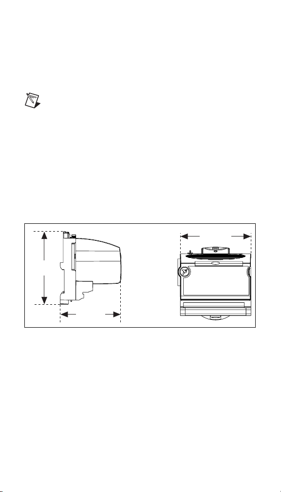
Mechanical Dimensions
Figure 13 shows the mechanical dimensions of the FP-CTR-502
installed on a terminal base. If you are using the cFP-CTR-502,
refer to your Compact FieldPoint controller user manual for the
dimensions and cabling clearance requirements of the Compact
FieldPoint system.
107.19 mm
(4.22 in.)
109.5 mm
(4.31 in.)
91.44 mm
(3.60 in.)
Figure 13. FP-CTR-502 Mechanical Dimensions
© National Instruments Corp. 21 FP-CTR-502 and cFP-CTR-502
Page 22

Where to Go for Support
For more information about setting up the FieldPoint system, refer
to these National Instruments documents:
• FieldPoint network module user manual
• Other FieldPoint I/O module operating instructions
• FieldPoint terminal base and connector block operating
instructions
Go to
ni.com/support for the most current manuals, examples,
and troubleshooting information.
For telephone support in the United States, create your service
request at ni.com/support and follow the calling instructions or
dial 512 795 8248. For telephone support outside the United
States, contact your local branch office:
Australia 1800 300 800, Austria 43 0 662 45 79 90 0,
Belgium 32 0 2 757 00 20, Brazil 55 11 3262 3599,
Canada (Calgary) 403 274 9391,
Canada (Montreal) 514 288 5722,
Canada (Ottawa) 613 233 5949, Canada (Québec) 514 694 8521,
Canada (Toronto) 905 785 0085,
Canada (Vancouver) 514 685 7530, China 86 21 6555 7838,
Czech Republic 420 2 2423 5774, Denmark 45 45 76 26 00,
Finland 385 0 9 725 725 11, France 33 0 1 48 14 24 24,
Germany 49 0 89 741 31 30, Greece 30 2 10 42 96 427,
India 91 80 51190000, Israel 972 0 3 6393737,
Italy 39 02 413091, Japan 81 3 5472 2970,
Korea 82 02 3451 3400, Malaysia 603 9131 0918,
Mexico 001 800 010 0793, Netherlands 31 0 348 433 466,
New Zealand 1800 300 800, Norway 47 0 66 90 76 60,
Poland 48 0 22 3390 150, Portugal 351 210 311 210,
Russia 7 095 238 7139, Singapore 65 6226 5886,
Slovenia 386 3 425 4200, South Africa 27 0 11 805 8197,
Spain 34 91 640 0085, Sweden 46 0 8 587 895 00,
Switzerland 41 56 200 51 51, Taiwan 886 2 2528 7227,
Thailand 662 992 7519, United Kingdom 44 0 1635 523545
FP-CTR-502 and cFP-CTR-502 22 ni.com
 Loading...