

Page 1

National Instruments FP-AI-102 Manual
Get Pricing & Availability at
ApexWaves.com
Call Today: 1-800-915-6216
Email: sales@apexwaves.com
https://www.apexwaves.com/modular-systems/national-instruments/fieldpoint/FP-AI-102
Page 2

FieldPoint Operating Instructions
FP-AI-102 AND CFP-AI-102
Eight-Channel, High-Voltage,
12-Bit Analog Input Modules
These operating instructions describe how to install and use the
FP-AI-102 and cFP-AI-102 analog input modules (referred to
inclusively as the [c]FP-AI-102). For information about
configuring and accessing the [c]FP-AI-102 over a network, refer
to the user manual for the FieldPoint network module you are
using.
Features
The [c]FP-AI-102 is a FieldPoint analog input module with the
following features:
• Eight analog voltage input channels
• Six input ranges: 0–20, 0–60, 0–120, ±20, ±60, and ±120 V
• 12-bit resolution
• 2,300 V transient overvoltage protection between the
inter-module communication bus and the I/O channels
•250 V
isolation voltage rating
rms
• –40 to 70 °C operation
• Hot plug-and-play
Installing the FP-AI-102
The FP-AI-102 mounts on a FieldPoint terminal base (FP-TB-x).
Hot plug-and-play enables you to install the FP-AI-102 onto a
powered terminal base without disturbing the operation of other
modules or terminal bases. The FP-AI-102 receives operating
power from the terminal base.
FieldPoint™, National Instruments™, NI™, and ni.com™ are trademarks of National Instruments Corporation.
Product and company names mentioned herein are trademarks or trade names of their respective companies.
For patents covering National Instruments products, refer to the appropriate location: Help»Patents in your software,
the
patents.txt file on your CD, or ni.com/patents.
323279A-01 October 2002
© 2002 National Instruments Corp. All rights reserved.
Page 3

To install the FP-AI-102, refer to Figure 1 and complete the
following steps:
1. Slide the terminal base key to either position X (used for any
module) or position 1 (used for the FP-AI-102 module).
2. Align the FP-AI-102 alignment slots with the guide rails on the
terminal base.
3. Press firmly to seat the FP-AI-102 on the terminal base. When
the module is firmly seated, the terminal base latch locks it into
place.
Key
Latch
Alignment
Slot
Guide Rails
Terminal BaseI/O Module
Figure 1. Installing the FP-AI-102
Installing the cFP-AI-102
The cFP-AI-102 mounts on a Compact FieldPoint backplane
(cFP-BP-x). Hot plug-and-play enables you to install the
cFP-AI-102 onto a powered backplane without disturbing the
operation of other modules or connector blocks. The cFP-AI-102
receives operating power from the backplane.
To install the cFP-AI-102, refer to Figure 2 and complete the
following steps:
1. Align the captive screws on the cFP-AI-102 with the holes on
the backplane. The alignment keys on the cFP-AI-102 prevent
backward insertion.
2. Press firmly to seat the cFP-AI-102 on the backplane.
3. Using a number 2 Phillips screwdriver with a shank of at least
64 mm (2.5 in.) length, tighten the captive screws to 1.1 N ⋅ m
(10 lb ⋅ in.) of torque. The nylon coating on the screws prevents
them from loosening.
FP-AI-102 and cFP-AI-102 2 ni.com
Page 4

2 1
4
4
5
5
3
1 cFP Backplane
2 cFP Controller Module
Figure 2. Installing the cFP-AI-102
3cFP-AI-102
4 Captive Screws
5 Screw Holes
Wiring the [c]FP-AI-102
The FP-TB-x terminal bases have connections for each of the eight
input channels on the FP-AI-102 and for an external supply to
power field devices. The cFP-CB-x connector blocks provide the
same connections for the cFP-AI-102.
Table 1 lists the terminal assignments for the signals associated
with each channel. The terminal assignments are the same for the
FP-TB-x terminal bases and the cFP-CB-x connector blocks.
© National Instruments Corp. 3 FP-AI-102 and cFP-AI-102
Page 5

Table 1. Term ina l As sig nments
Terminal Numbers
Channel
0 1 17 2, 18
1 3 19 4, 20
2 5 21 6, 22
3 7 23 8, 24
4 9 25 10, 26
5 11 27 12, 28
6 13 29 14, 30
7 15 31 16, 32
V
in
V
sup
COM
Each channel has one input terminal (Vin) for voltage input. All
eight voltage inputs share a common ground reference, the COM
terminals. If you are using an external supply to power field
devices, connect the power supply to the V and C terminals of the
terminal base or connector block. Field devices source power from
the V
and COM terminals. Refer to the following section for
sup
detailed wiring diagrams.
Caution Cascading power between two modules defeats
isolation between those modules. Cascading power from
the network module defeats all isolation between
modules in the FieldPoint system.
FP-AI-102 and cFP-AI-102 4 ni.com
Page 6
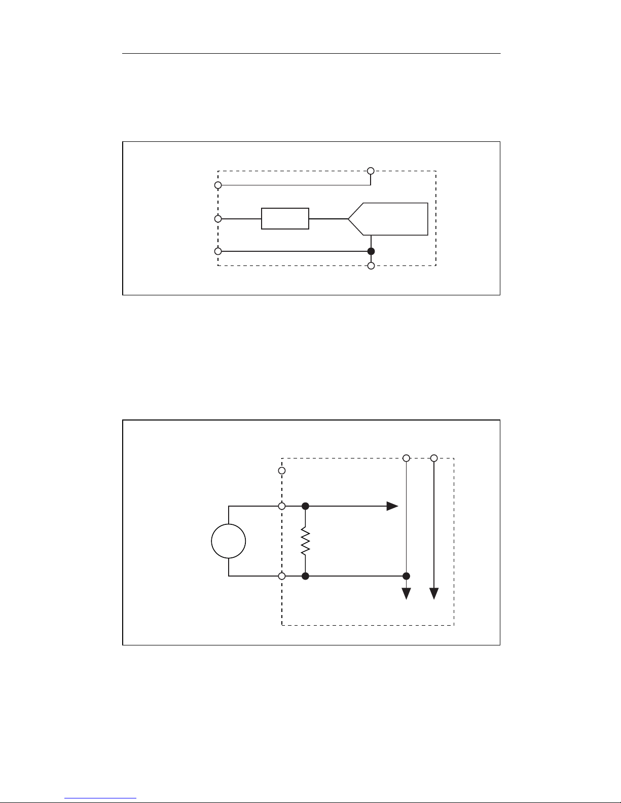
Measuring Voltage with the [c]FP-AI-102
The [c]FP-AI-102 has eight single-ended input channels. All eight
channels share a common ground reference that is isolated from
other modules in the FieldPoint system. Figure 3 shows the analog
input circuitry on one channel.
V
V
sup
V
COM
in
Filter
12-Bit
Isolated ADC
C
Figure 3. [c]FP-AI-102 Analog Input Circuit, One Channel
The input ranges for voltage signals are 0–20, 0–60, 0–120, ±20,
±60, and ±120 V. Connect the positive lead of a voltage source to
the V
terminal and the negative lead to the COM terminal.
in
Figure 4 shows how to connect a voltage source without an
external power supply to one channel of the [c]FP-AI-102.
[c]FP-AI-102
V
sup
V
in
To Analog
Input Circuitry
VC
Voltage
Source
Figure 4. Voltage Source without External Power Supply
© National Instruments Corp. 5 FP-AI-102 and cFP-AI-102
+
–
COM
1.0 MΩ
Input
Impedance
To Next
Channel
Page 7

Figure 5 show how to connect a voltage source with an external
power supply to one channel of the [c]FP-AI-102.
Powered
Voltage
Transducer
+
OUT
–
V
sup
V
COM
[c]FP-AI-102
in
External
Power
Supply
To Analog
Input Circuitry
1.0 MΩ
Input
Impedance
+
–
VC
To Next
Channel
Figure 5. Voltage Source with External Power Supply
Status Indicators
The [c]FP-AI-102 has two green status LEDs, POWER and
READY. After you insert the [c]FP-AI-102 into a terminal base or
backplane and apply power to the connected network module, the
green POWER indicator lights and the [c]FP-AI-102 informs the
network module of its presence. When the network module
recognizes the [c]FP-AI-102, it sends initial configuration
information to the [c]FP-AI-102. After the [c]FP-AI-102 receives
this initial information, the green READY indicator lights and the
module is in normal operating mode.
Upgrading the FieldPoint Firmware
You may need to upgrade the FieldPoint firmware when you add
new I/O modules to the FieldPoint system. For information on
determining which firmware you need and how to upgrade, go to
ni.com/info and enter fpmatrix.
FP-AI-102 and cFP-AI-102 6 ni.com
Page 8

Isolation and Safety Guidelines
Caution Read the following information before
attempting to connect the [c]FP-AI-102 to any circuits
that may contain hazardous voltages.
This section describes the isolation of the [c]FP-AI-102 and its
compliance with international safety standards. The field wiring
connections are isolated from the backplane and the inter-module
communication bus. The isolation is provided by the module,
which has optical and galvanic isolation barriers designed and
tested to protect against transient fault voltages of up to 2,300 V
The [c]FP-AI-102 provides double insulation (compliant with
1
IEC 61010-1) for working voltages of 250 V
. Safety standards
rms
(such as those published by UL and IEC) require the use of double
insulation between hazardous voltages and any human-accessible
parts or circuits.
Never try to use any isolation product between human-accessible
parts (such as DIN rails or monitoring stations) and circuits that
can be at hazardous potentials under normal conditions, unless the
product is specifically designed for such an application, as is the
[c]FP-AI-102.
rms
.
Even though the [c]FP-AI-102 is designed to handle applications
with hazardous potentials, follow these guidelines to ensure a safe
total system:
• The [c]FP-AI-102 has a safety isolation barrier between the
inter-module communication bus and the I/O channels. There
is no isolation between channels unless otherwise noted. If any
of the channels on a module are wired at a hazardous potential,
make sure that all other devices or circuits connected to that
module are properly insulated from human contact.
•Do not share the external supply voltages (the V and C
terminals) with other devices (including other FieldPoint
devices), unless those devices are isolated from human contact.
• For Compact FieldPoint, you must connect the protective earth
(PE) ground terminal on the cFP-BP-x backplane to the system
safety ground. The backplane PE ground terminal has the
following symbol stamped beside it: . Connect the
1
Working voltage is defined as the signal voltage plus the common-mode voltage.
Common-mode voltage is the voltage of the module with respect to ground.
© National Instruments Corp. 7 FP-AI-102 and cFP-AI-102
Page 9

backplane PE ground terminal to the system safety ground
using 14 AWG (1.6 mm) wire with a ring lug. Use the 5/16 in.
panhead screw shipped with the backplane to secure the ring
lug to the backplane PE ground terminal.
• As with any hazardous voltage wiring, make sure that all
wiring and connections meet applicable electrical codes and
commonsense practices. Mount terminal bases and backplanes
in an area, position, or cabinet that prevents accidental or
unauthorized access to wiring that carries hazardous voltages.
• The isolation of the [c]FP-AI-102 is certified as
double-insulated for working voltages of 250 V
. Do not use
rms
the [c]FP-AI-102 as the only isolating barrier between human
contact and working voltages of more than 250 V
rms
.
• Operate the [c]FP-AI-102 only at or below Pollution Degree 2.
Pollution Degree 2 means that only nonconductive pollution
occurs in most cases. Occasionally, however, a temporary
conductivity caused by condensation must be expected.
•Do not operate FieldPoint products in an explosive atmosphere
or where there may be flammable gases or fumes. If you need
to operate FieldPoint products in such an environment, the
FieldPoint products must be in a suitably rated enclosure.
• Operate the [c]FP-AI-102 at or below Installation Category II.
Installation Category II is for measurements performed on
circuits directly connected to the electrical distribution system.
This category refers to local-level distribution, such as that
provided by a standard wall outlet.
Specifications
The following specifications are typical for the range –40 to 70 °C
unless otherwise noted. Gain error is calculated as a percentage of
input.
Input Characteristics
Number of channels..........................8
ADC resolution.................................12 bits
Type of ADC.....................................Successive approximation
Update rate (all channels).................360 Hz (2.8 ms)
FP-AI-102 and cFP-AI-102 8 ni.com
Page 10

Input signal ranges (software selectable by channel)
Voltage
Input
Range
0–20 V 15 mV 20 mV 100 mV
0–60 V 40 mV 50 mV 150 mV
0–120 V 70 mV 100 mV 250 mV
±20 V 25 mV 40 mV 175 mV
±60 V 70 mV 120 mV 350 mV
±120 V 125 mV 220 mV 700 mV
*
Includes quantization errors and rms noise.
Effective
Resolution
*
Typical
Offset Error
to 35 °C
at 15
Maximum
Offset Error
at –40 to 70 °C
Gain error
15 to 35 °C .................................0.1% typ, 0.2% max
–40 to 70 °C ...............................0.2% typ, 0.3% max
Input impedance................................1.0 MΩ
Input noise ........................................7 mV + 1 LSB peak-to-peak
Signal input bandwidth.....................170 Hz
Physical
Indicators .......................................... Green POWER and
READY indicators
Weight
FP-AI-102...................................145 g (5.1 oz)
cFP-AI-102.................................115 g (4.0 oz)
Power Requirements
Power from network module ............400 mW
Isolation Voltage
Maximum isolation voltage ..............250 V
Category II
Channel-to-channel isolation ............No isolation between
channels
, Installation
rms
Transient overvoltage........................ 2,300 V
© National Instruments Corp. 9 FP-AI-102 and cFP-AI-102
rms
Page 11

Environmental
FieldPoint modules are intended for indoor use only. For outdoor
use, they must by mounted inside a sealed enclosure.
Operating temperature ......................–40 to 70 °C
Storage temperature..........................–55 to 100 °C
Humidity...........................................10 to 90% RH,
noncondensing
Maximum altitude.............................2,000 m
Pollution Degree ............................... 2
Shock and Vibration
Operating shock (IEC 68-2-27)
cFP-AI-102
.................................50 g, 3 ms half sine, 3 shocks;
30 g, 11 ms half sine,
3 shocks
Operating vibration, random (IEC 60068-2-34)
FP-AI-102................................... 10–500 Hz, 2.2 g
cFP-AI-102.................................10–500 Hz, 5 g
rms
rms
Operating vibration, sinusoidal (IEC 60068-2-6)
[c]FP-AI-102 ..............................10–500 Hz, 5 g
Safety
The [c]FP-AI-102 is designed to meet the requirements of the
following standards for safety and electrical equipment for
measurement, control, and laboratory use.
• EN 61010-1, IEC 61010-1
• UL 3121-1
• CAN/CSA C22.2 No. 1010.1
For certifications under regulatory standards, including hazardous
location standards, refer to the product label or to
FP-AI-102 and cFP-AI-102 10 ni.com
ni.com.
Page 12
Electromagnetic Compatibility
CE, C-Tick, and FCC Part 15 (Class A) Compliant
Electromagnetic emissions ...............EN 55011 Class A at 10 m
FCC Part 15A above 1 GHz
Electromagnetic immunity................Evaluated to EN 61326:
1997/A1: 1998, Table 1
Note For full EMC compliance, you must operate this
device with shielded cabling. See the Declaration of
Conformity (DoC) for this product for any additional
regulatory compliance information. To obtain the DoC
for this product, click Declaration of Conformity at
ni.com/hardref.nsf/.
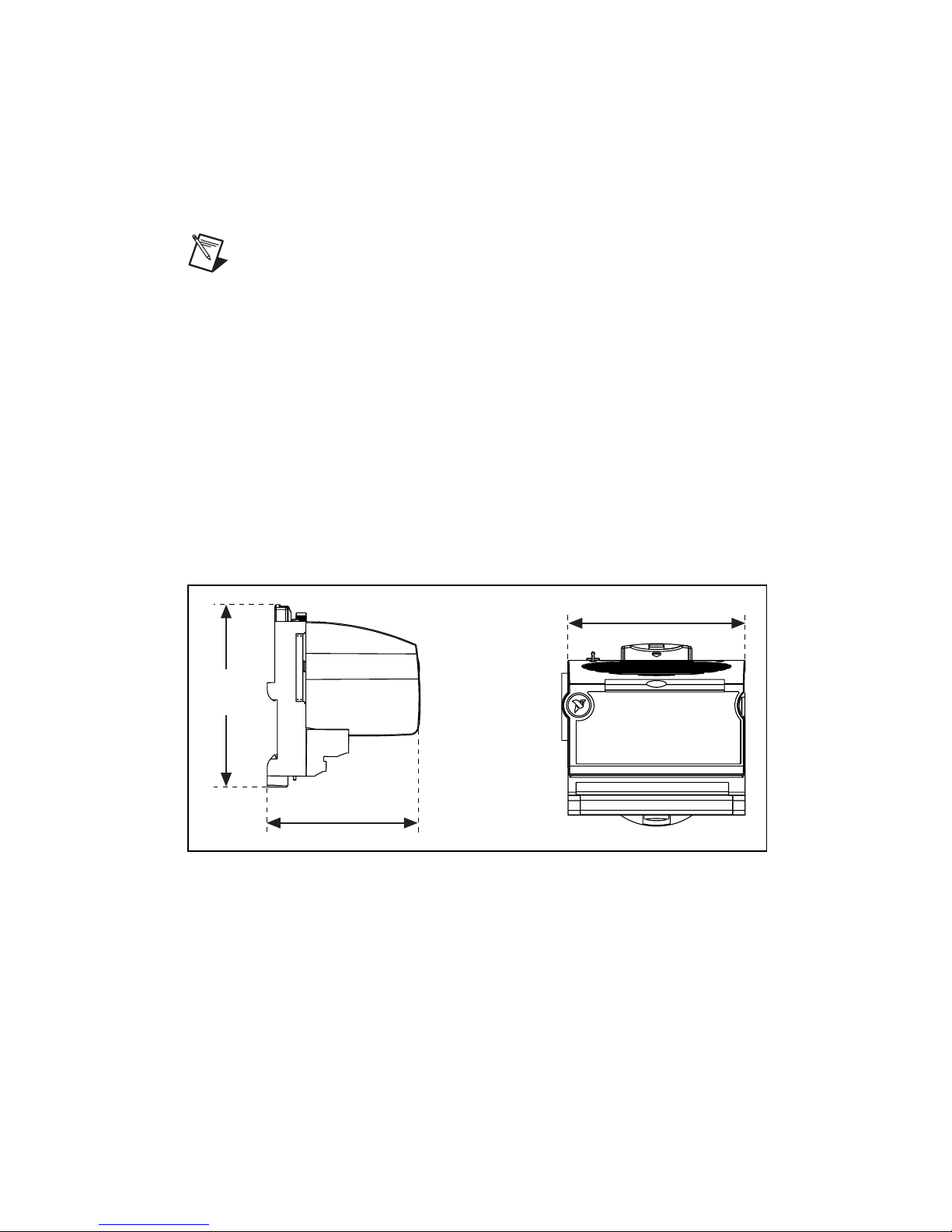
Mechanical Dimensions
Figure 6 shows the mechanical dimensions of the FP-AI-102
installed on a terminal base. Dimensions are given in millimeters
[inches]. If you are using the cFP-AI-102, refer to the cFP
controller user manual for the dimensions and cabling clearance
requirements of the Compact FieldPoint system.
109.5
[4.31]
107.19 [4.22]
91.44 [3.60]
Figure 6. FP-AI-102 Mechanical Dimensions
© National Instruments Corp. 11 FP-AI-102 and cFP-AI-102
Page 13

Where to Go for Support
For more information about setting up the FieldPoint system, refer
to these National Instruments documents:
• FieldPoint network module user manual
• Other FieldPoint I/O module operating instructions
• FieldPoint terminal base operating instructions
Go to
and troubleshooting information.
For telephone support in the United States, create your service
request at ni.com/ask and follow the calling instructions or dial
512 795 8248. For telephone support outside the United States,
contact your local branch office:
Australia 03 9879 5166, Austria 0662 45 79 90 0,
Belgium 02 757 00 20, Brazil 55 11 3262 3599,
Canada (Calgary) 403 274 9391,
Canada (Montreal) 514 288 5722,
Canada (Ottawa) 613 233 5949, Canada (Québec) 514 694 8521,
Canada (Toronto) 905 785 0085, China 86 21 6555 7838,
Czech Republic 02 2423 5774, Denmark 45 76 26 00,
Finland 09 725 725 11, France 01 48 14 24 24,
Germany 089 741 31 30, Greece 01 42 96 427,
Hong Kong 2645 3186, India 91 80 4190000,
Israel 03 6393737, Italy 02 413091, Japan 03 5472 2970,
Korea 02 3451 3400, Malaysia 603 9596711,
Mexico 001 800 010 0793, Netherlands 0348 433466,
New Zealand 09 914 0488, Norway 32 27 73 00,
Poland 22 3390 150, Portugal 210 311 210, Russia 095 238 7139,
Singapore 65 6 226 5886, Slovenia 3 425 4200,
South Africa 11 805 8197, Spain 91 640 0085,
Sweden 08 587 895 00, Switzerland 056 200 51 51,
Taiwan 02 2528 7227, United Kingdom 01635 523545
ni.com/support for the most current manuals, examples,
*323279A-01*
323279A-01 Oct02
 Loading...