

Page 1

FieldPoint™ FP-1000 and
FP-1001 RS-232/RS-485
Network Module
User Manual
FieldPoint FP-1000/FP-1001 User Manual
July 1997 Edition
Part Number 321631A-01
© Copyright 1997 National Instruments Corporation. All rights reserved.
Page 2
Internet Support
support@natinst.com
E-mail: info@natinst.com
FTP Site: ftp.natinst.com
Web Address: http://www.natinst.com
Bulletin Board Support
BBS United States: (512) 794 -5422
BBS United Kingdom: 01635 551422
BBS France: 01 48 65 15 5 9
Fax-on-Demand Support
(512) 418-1111
Telephone Support (U.S.)
Tel: (512) 795-8248
Fax: (512) 794-5678
International Offices
Australia 03 9879 5166, Austria 0662 45 79 90 0, Belgium 02 757 00 20,
Canada (Ontario) 905 785 0085, Canada (Québec ) 514 694 8521, Denmark 45 76 26 00,
Finland 09 725 725 11, France 01 48 14 24 24, Germany 089 741 31 30,
Hong Kong 2645 3186, Israel 03 5734815, Ital y 02 413091, Jap an 03 5472 2970,
Korea 02 596 7456, Mexico 5 520 2635, Nethe rlands 034 8 433466, Nor way 32 84 84 00,
Singapore 2265886, Spain 91 640 0085, Swede n 08 730 49 70, Switzerland 056 200 51 51,
Taiwan 02 377 1200, United Kingdom 01635 523545
National Instruments Corporate Headquarters
6504 Bridge Point Parkw ay Austin, TX 78730-503 9 Tel: (512) 794-0100
Page 3

Important Information
Warranty
The FieldPoint modules are warranted against defects in materials and workmanship for a period of one year from the
date of shipment, as evidenced by receipts or other documentation. National Instruments will, at its option, repair or
replace equipment that proves to be defective during the warranty period. This warranty includes parts and labor.
The media on which you receive National Instru ments software ar e warranted not to fail to execute pro grammi ng
instructions, due to defects in materials and workmanship, for a period of 90 days from date of shipment, as evidenced
by receipts or other documentation. National Instruments will, at its option, repair or replace soft ware media that do
not execute programming instructions if National Instruments receives notice of such defects during the warranty
period. National Instrument s does not war rant that the oper ation of the softwar e shall be un interr upted or error free.
A Return Material Authorization (RMA) number must be obtained from the factory and clearly marked on the outside
of the package before any equipment will be accepted for warranty work. National Instruments will pay the shipping
costs of returning to the owner par ts whi ch are cov ered by w arranty .
National Instruments believes that the information in this manual is accurate. The document has been carefully
reviewed for technical accuracy. In the event that technical or typographical errors exist, National Instruments reserves
the right to make ch anges to subsequent editions of this document without prior not ice to holders of th is edition. The
reader should consult National Instruments if errors are suspected. In no event shall National Instruments be liable for
any damages arising out of or related to this docum ent or the in format ion contai ned in it.
E
XCEPT AS SPECIFIED HEREIN
SPECIFICALLY DISCLAIMS ANY WARRANTY OF MERCHANTABILITY OR FITNESS FOR A PARTICULAR PURPOSE
C
USTOMER’S RIGHT TO RECOVER DAMAGES CAUSED BY FAULT OR NEGLIGENCE ON THE PART OF NATIONAL
I
NSTRUMENTS SHALL BE LIMITED TO THE AMOUNT THERETOFORE PAID BY THE CUSTOMER
WILL NOT BE LIABLE FOR DAMAGES RESULTING FROM LOSS OF DATA, PROFITS, USE OF PRODUCTS, OR INCIDENTAL OR
CONSEQUENTIAL DAMAGES, EVEN IF ADVISED OF THE POSSIBILITY THEREOF
Instruments will apply regardles s of the fo rm of acti on, whether i n contract or tort, incl uding neg lig ence. Any acti on
against National Instruments must be brought wit hin one year after the cause of action accrues. Nat ion al Instrument s
shall not be liable for any delay in performan ce due to causes beyo nd it s reasonable cont rol. The warranty pr ovided
herein does not cover damages, defects, malf unctio ns, or s ervice fai lures caused by owne r’s fail ure to fol low the
National Instruments in sta llat ion, o perat ion, or ma inte na nce instr uct ions; owner ’s modif icat ion of the p roduct;
owner’s abuse, misuse, or negligent acts; and power failure or surges, fire, flood, accident, actions of third parties, or
other events outside reasonable control.
, N
ATIONAL INSTRUMENTS MAKES NO WARRANTIES, EXPRESS OR IMPLIED, AND
.
. N
ATIONAL INSTRUMENTS
. This limitation of the liability of National
Copyright
Under the copyright laws, this publication may not be reproduced or transmitted in any form, electronic or mechanical,
including photocopying, reco rding, storin g in an in format ion retr iev al system , or tra nslati ng, in wh ole or in par t,
without the prior written consent of Nation al Inst rument s Corpo ration .
Trademarks
BridgeVIEW™, FieldPoint™, Lab VIEW™ , and Lookou t™ are trad emarks of Nat ional Inst ru ments Corpo ration.
Product and company names listed are trademarks or trade names of their respective companies.
WARNING REGARDING MEDICAL AND CLINICAL USE OF NATIONAL INSTRUMENTS PRODUCTS
National Instruments products are not design ed with comp onents and testing in tend ed to ensure a level o f reliabi lity
suitable for use in treatment and diag nosi s of humans . Appli cations of Nation al Instru men ts product s invol vin g
medical or clinical treatment can create a potential for accidental injury caused by product failure, or by errors on the
part of the user or application designer . Any us e or applicat ion of Nat ional Ins trum ent s products for or involvi ng
medical or clinical treatment must be performed by properly trained and qualified medical personnel, and all traditional
medical safeguards, equipment, and procedures that are appropriate in the particular situation to prevent serious injury
or death should always continue to be used when National Instruments prod ucts ar e being used. National Instruments
products are NOT intended to be a substitute f or any for m of establ ished pr ocess, proce dure, or equi pmen t used to
monitor or safegua rd huma n he alth and sa fety in med ical or clin ical t reat ment .
Page 4

About This Manual
How to Use This Manual Set........................................................................................ix
Organization of This Manual........................................................................................x
Conventions Used in This Manual................................................................................ x
Related Documentation.................................................................................................xi
Customer Communication.............................. ..... .........................................................xi
Chapter 1
FP-1000 and FP-1001 Network Module Overview
FP-1000 Connects to RS-232 .......................................................................................1-1
FP-1001 Connects to RS-485 .......................................................................................1-2
Chapter 2
Installation and Configuration
Installing the Network Module.....................................................................................2-1
Removing the Network Module ...................................................................................2-2
Connecting Terminal Bases..........................................................................................2-2
Connecting the FP-1000 to the Network......................................................................2-3
Connecting the FP-1001 to the Network......................................................................2-4
Connecting to the Serial Ports ......................................................................................2-5
RS-232 Interface Specifications.....................................................................2-6
RS-485 Interface Specifications.....................................................................2-7
RS-485 Network Termination and Biasing....................................................2-7
Configuring the Network Module.................................................................................2-9
Setting the Network Address.......................................................................... 2-10
Setting the Baud Rate.....................................................................................2-12
Connecting Power to the FP-1000 or FP-1001.............................................................2-12
Calculating Power for a FieldPoint Bank.....................................................................2-13
Table of
Contents
Chapter 3
Feature Set Description
High-Speed Local Bus.............................. ....................................................................3-1
Network Watchdog Timer............................................................................................3-1
©
National Instruments Corporation v FieldPoint FP-1000/FP-1001 User Manual
Page 5

Table of Contents
SnapShot Feature.......................................................................................................... 3-2
Programmable Power-Up State....................................................................................3-3
HotPnP (Hot Plug and Play)......................................................................................... 3-4
HotPnP During Power-Up ............................................................................. 3-4
HotPnP During Operation.............................................................................. 3-5
Inserting New I/O Modules.............................................................3-5
Replacing I/O Modules....................................................................3-5
Power-On Self Test (POST).........................................................................................3-6
LED Indicators ........................................................ ...... ............................................... 3-7
Chapter 4
Using the FieldPoint Software
FieldPoint Software Overview..................................................................................... 4-1
Using the FieldPoint Explorer...................................................................................... 4-2
Using the FieldPoint Server with BridgeVIEW........................................................... 4-2
Using the FieldPoint Server with LabVIEW................................................................4-3
Using the FieldPoint Server with LabWindows/CVI................................................... 4-3
Using the FieldPoint Lookout Driver ........................................................................... 4-4
Using FieldPoint with Optomux Servers......................................................................4-4
Appendix A
Specifications
Appendix B
Customer Communication
Glossary
Index
Figures
Figure 2-1. DIN Rail Clip in the Unlocked Position................................................ 2-1
Figure 2-2. Installing the Network Module onto a DIN Rail...................................2-1
Figure 2-3. Locking the FieldPoint Network Module onto a DIN Rail................... 2-2
Figure 2-4. Connecting Terminal Bases................................................................... 2-3
Figure 2-5. Host Computer Connected to One FP-1000 and Two FP-1001
Network Modules.................................................................................. 2-4
Figure 2-6. Host Computer Connected to Three FP-1001 Network Modules......... 2-5
Figure 2-7. RS-232 Connector Pinout for the FP-1000........................................... 2-6
FieldPoint FP-1000/FP-1001 User Manual vi
©
National Instruments Corporation
Page 6

Tables
Table of Contents
Figure 2-8. RS-485 Connector Pinout for the FP-1000 and FP-1001......................2-7
Figure 2-9. Terminating RS-485 Using the Combicon Adapter ..............................2-8
Figure 2-10. Typical Signal Connections for Host Computer Connected to
One FP-1000 and Multiple FP-1001 Network Modules........................2-8
Figure 2-11. Typical Signal Connections for Host Computer Connected to
Multiple FP-1001 Network Modules.....................................................2-9
Figure 2-12. Address and Baud Rate Switch..............................................................2-9
Figure 2-13. FP-1000 and FP-1001 Power Connector Pinout....................................2-13
Figure 3-1. LEDs on the FP-1000 and FP-1001.......................................................3-7
Table 2-1. Network Address Switch Settings for the FP-1000 and FP-1001
Network Modules ..................................................................................2-11
Table 2-2. Baud Rate Switch Settings for the FP-1000 and FP-1001
Network Modules ..................................................................................2-12
Table 3-1. Module Configuration Results After HotPnP Replacement..................3-6
Table 3-2. STATUS LED Flashes and Corresponding Error Conditions...............3-8
©
National Instruments Corporation vii FieldPoint FP-1000/FP-1001 User Manual
Page 7
This manual describes how to install and use the FieldPo int FP-1000
and FP-1001 network modules.
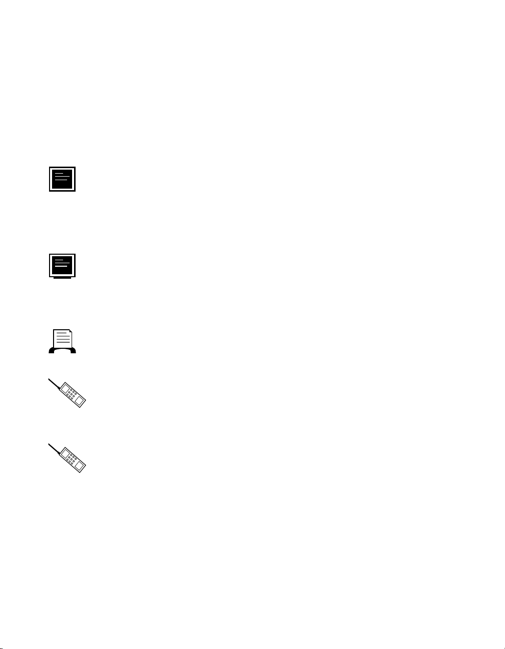
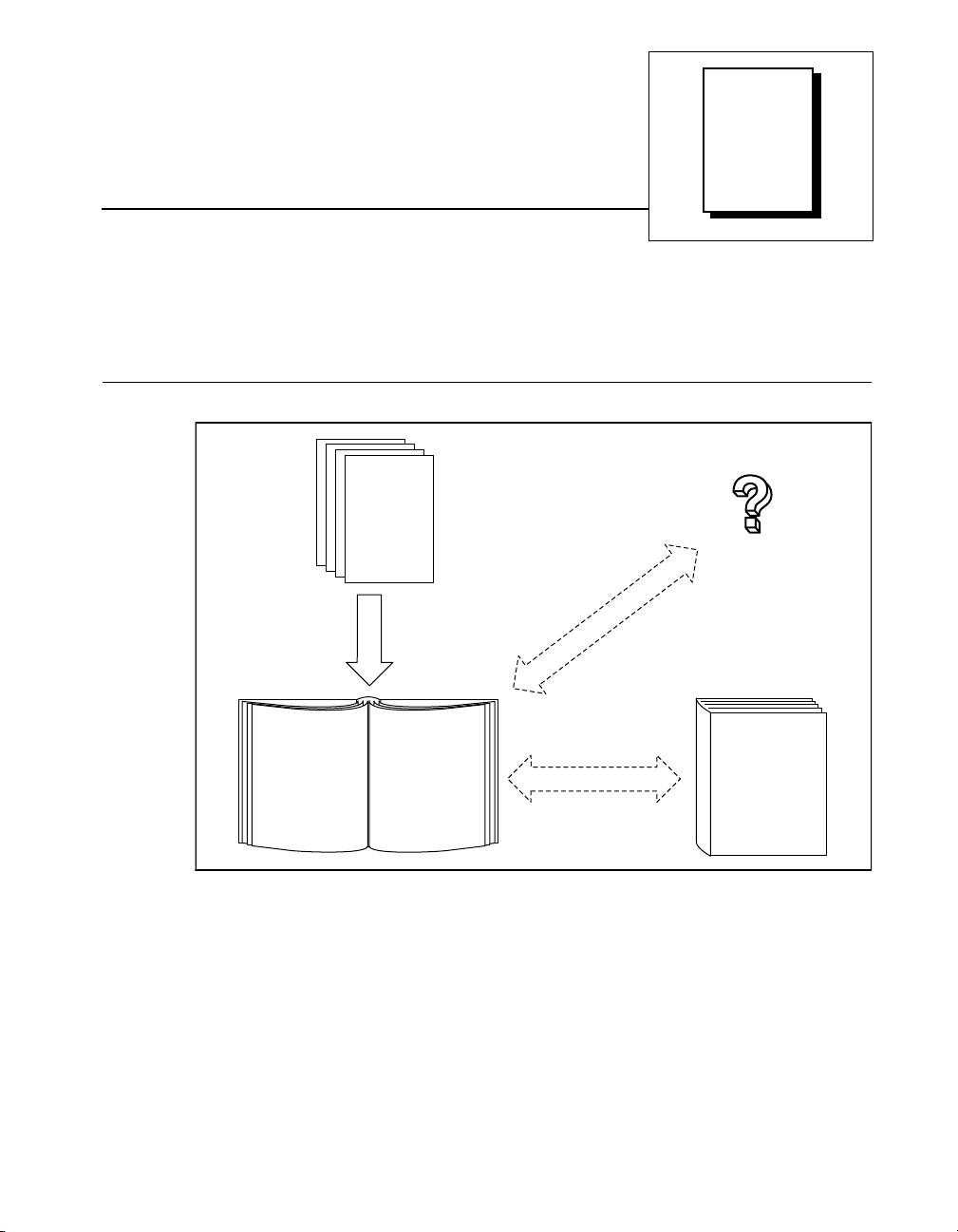
How to Use This Manual Set
Operating
Instructions
for Modules
and Bases
Installation
Specifications
About
This
Manual
FieldPoint Server
Online Help
FieldPoint
FieldPoint
User Manual
©
National Instruments Corporation ix FieldPoint FP-1000/FP-1001 User Manual
Network Connection,
Hardware
Configuration, and
Feature Set
Description
Programmer
Reference
Manual
Command Syntax
Page 8

About This Manual
Organization of This Manual
This manual is or ganize d as f ollow s:
• Chapter 1, FP-1000 and FP -10 01 Ne twork Mo dule O verv iew ,
provides an overview of the Field Point n etwork m od ules.
• Chapter 2, Installation and Configuration, describes how to install
and configure your Field Point n etwor k modu le, conn ect it to a n
RS-232 or RS-485 netw ork, an d con nect p ower to the networ k
module.
• Chapter 3, Feature Set Description, describes the feature set for the
FP-1000 and FP-1001 network module s.
• Chapter 4, Using the FieldPoint Software, describes ho w to use th e
FieldPoint hardware with various serv ers and softwa re pack ages.
• Appendix A, Specifications, describes the specifications of the
FP-1000 and FP-1001 network module s.
• Appendix B, Customer Communication, co ntain s f orm s y ou ca n
use to request help from National Instruments or to comment on our
products and manuals.
•The Glossary contains an alphabetical list and description of terms
used in this manual, including abbreviations, acronym s, metric
prefixes, mnemonics, and symbols.
•The Index cont ains a n al phabe tical list o f key te rms a nd topic s in
this manual, including the page n umb er w here you c an fin d e ach
one.
Conventions Used in This Manual
The following conventions are used in this manual:
This icon to the left of bold italicized text denotes a note, which alerts
you to important information.
!
bold Bold text denotes the names of menus, menu items, parameters, dialog
bold italic Bold italic text denotes a note, caution, or warning.
FieldPoint FP-1000/FP-1001 User Manual x
This icon to the left of bold italicized text denotes a caution, which
advises you of precau tions to take to av oid injury , d ata lo ss, or a
system crash.
box, dialog box buttons or o ptions, ico ns, window s, Windo ws 95 tabs,
or LEDs.
©
National Instruments Corporation
Page 9

About This Manual
italic Italic text denotes emphasis, a cross reference, or an introduction to a
key concept. This font also deno tes text from which y ou supply the
appropriate word or v alue, as in Wind ow s 3 .x .
italic monospace
monospace Text in this font denotes text or characters that should literally enter
Italic text in this font denotes th at you mu st su pply the appr opriate
words or values in the place of these items.
from the keyboard, sections of co de, pro gramming ex ample s, and
syntax examples. This font is also used for the pro per names of disk
drives, paths, directories, programs, subprogram s, subroutines, device
names, functions, operations, variables, file names and exten sions, and
for statements and c omm en ts take n from p rogra ms.
Related Documentation
The following documents contain information that you may find helpful
as you read this manual:
• Operating Instruction s (f or ne twork m odu le, ter minal base s, a nd
I/O modules)
• FieldPoint Server Online Help
Customer Communication
National Instruments wants to rece ive you r com ments o n ou r prod ucts
and manuals. We are interested in the applications you develop with our
products, and we want to help if you have problems with them. To make
it easy for you to contact us, this manual contains comment and
configuration forms for you to complete. These for ms are in
Appendix B, Customer Communication, at the end of this manual.
©
National Instruments Corporation xi FieldPoint FP-1000/FP-1001 User Manual
Page 10

FP-1000 and FP-1001
Chapter
Network Module Overview
This chapter prov ides an o ve rview of the Fie ldPoin t ne twork mo dules .
The FP-1000 FieldPoint network module connects an industrial RS-232
network to FieldPoint I/O modu les. The FP-1001 Fiel dPoint ne twork
module connects an industrial RS-485 netwo rk to FieldPoint I/O
modules.
The FP-1000 and FP-1001 support stan dard co mmands (subs et of
Optomux command set), and a set of extended commands to completely
support the FieldPoint I/O modules. Both network modules can co-exist
with other Optomux devices on the same network.
The FP-1000 and FP-10 01 use the Op tomux p rotocol. The refor e, a f ter
you have configure d the FieldPoin t ba nk ( ne twork mod ule a nd I/O
modules), you can use any application software that supports Optomux
to communicate wi th Field Point m od ules in the ba nk.
In a distributed application, many FieldPo int ba nks a re n etwor ked
together. You can netw ork up to 25 FieldPoi nt bank s to each
RS-232/RS-485 port of y our ho st c ompute r. Eac h ban k ca n c ont ain up
to nine I/O modules, thus connecting up to 225 I/O modules per RS-232
(or RS-485) port in your host co mpu ter. You c an furth er in cr ease you r
field I/O count by using more RS-232/RS-485 por ts in your host
computer.
1
FP-1000 Connects to RS-232
The FP-1000 connec ts dir ectly to the RS- 232 p ort that is a vailable on
most host computers. Since RS-232 is a point-to-poin t network that
allows connection to only one device, the FP-1000 provides an RS-485
repeater so that you can build a network with multiple FieldPoint banks.
©
National Instruments Corporation 1-1 FieldPoint FP-1000/FP-1001 User Manual
Page 11

Chapter 1 FP-1000 and FP-1001 Network Module Overview
FP-1001 Connects to RS-485
The FP-1001 FieldPoint netw ork modu le co nnects dire ctly to an
RS-485 adapter card that is installed in your host computer. Since
RS-485 is inherently a multidrop n etwork , the FP-1001 do es not
provide a separate RS-485 repeater. You can network multiple FP-1001
modules in multidrop fashion.
The FP-1001 communicates over RS-485, utilizing full-duplex mode. It
is optically isolated, which prevents fault coupling between the RS-485
network and the FP-1001.
FieldPoint FP-1000/FP-1001 User Manual 1-2
©
National Instruments Corporation
Page 12
Installation and
Chapter
Configuration
This chapter describes how to insta ll a nd co nfig ure y our FieldP oint
network module, connect it to an RS-232 or RS-485 network, a nd
connect power to the netwo rk module.
Installing the Network Module
The FieldPoint network m odule s ha ve rugge d, simple clips fo r
mounting reliably onto a standard 35 mm DIN rail. Follow these step s
to mount the network module onto a DIN rail. Terminal ba ses must be
connected to the network module before power is applied.
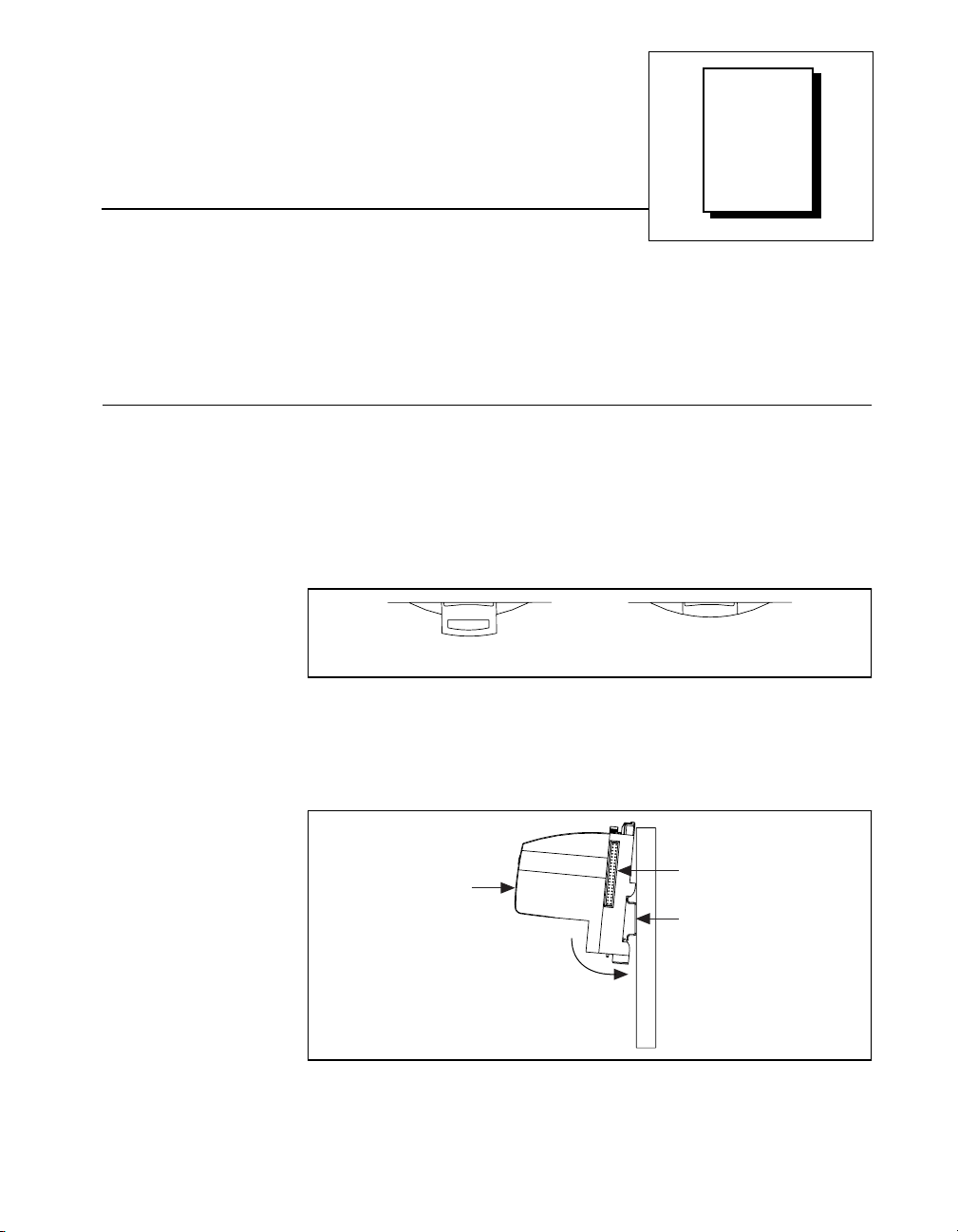
1. Use a flat-bladed screwdriver to open the DIN rail clip to the
unlocked position, as shown in Figure 2-1.
Figure 2-1.
2. Hook the lip on the rear of the network module onto the top of a
35 mm DIN rail and press the ne twork module down onto the DIN
rail as shown in Figure 2-2.
2
Rail Clip LockedRail Clip Unlocked
DIN Rail Clip in the Unlocked Position
Local Bus
Cover
Press
Figure 2-2.
©
National Instruments Corporation 2-1 FieldPoint FP-1000/FP-1001 User Manual
Installing the Network Module onto a DIN Rail
Connector
DIN Rail
Page 13
Chapter 2 Installation and Configuration
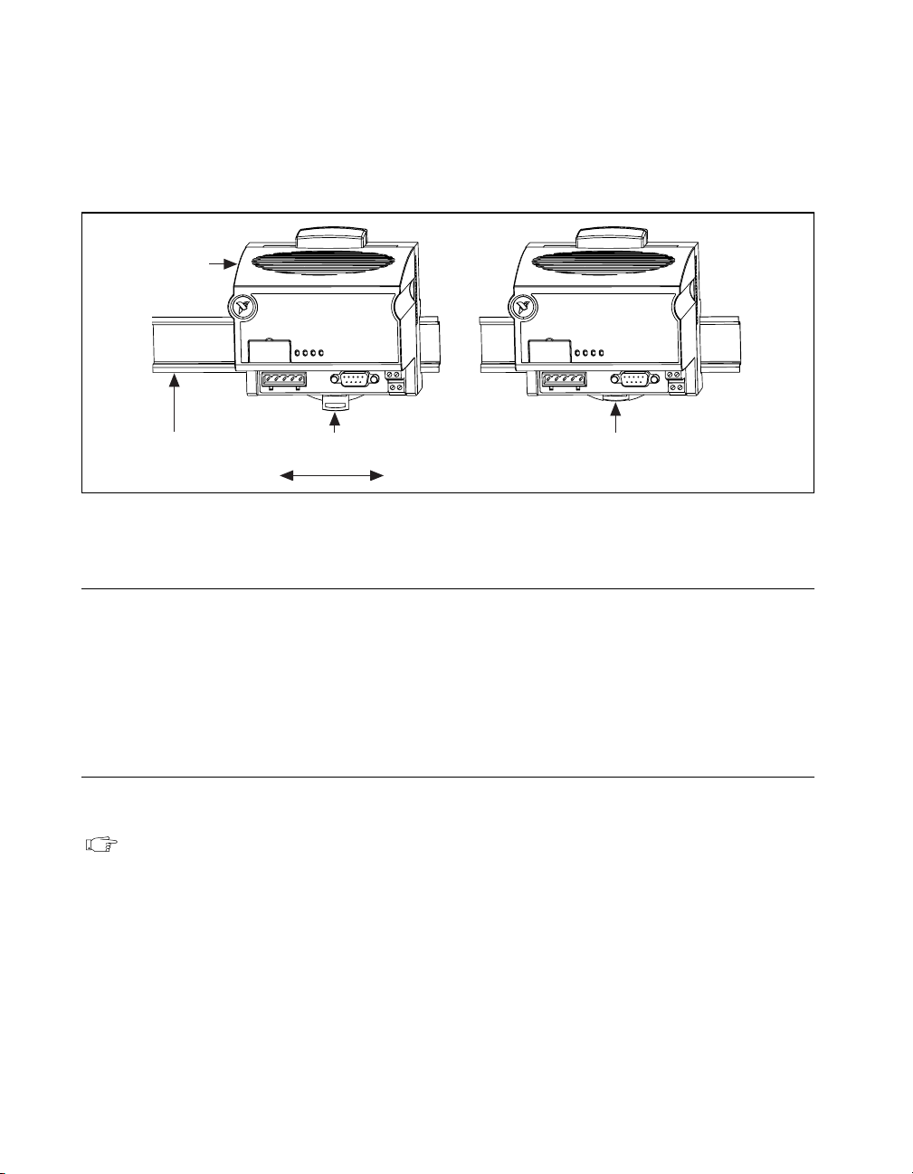
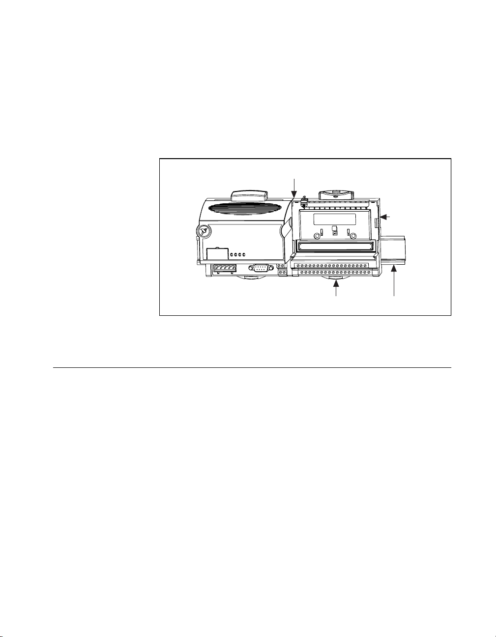
3. Slide the network modu le to the desir ed po sition o n th e D IN r ail.
After the module is in position, push the rail snap into the locked
position to lock the module in place on the DIN rail, as shown in
Figure 2-3.
Network
Module
DIN
Rail
Rail Snap Unlocked
(Position Module Along DIN Rail)
Figure 2-3. Locking the FieldPoint Network Module onto a DIN Rail
Removing the Network Module
To remove a network module, unlock it from the DIN rail by placing a
screwdriver in the slot on the rail snap a nd o pen ing it to th e unloc ked
position as shown in Figure 2-1. T hen d isco nnect the termina l b ase
from the network module’s local bus connector, and lift the module off
of the rail.
Connecting Terminal Bases
Follow these steps to connect a terminal base and a network module.
Note: Ensure that power is not applied to the network module, before you install
or remove terminal bases.
1. Remove the protective cover from the network module’s local bus
connector (see Figure 2-2).
2. Install the terminal base onto the DIN rail in the same way you
installed the network module. Refer to the operating instructions
for the FP-TB-1/2 more information on how to install your terminal
base onto the DIN rail.
Rail Snap
Locked
FieldPoint FP-1000/FP-1001 User Manual 2-2
©
National Instruments Corporation
Page 14
Chapter 2 Installation and Configuration
3. Attach the terminal base to the network module by firm ly m ating
the local bus connectors.
4. To add more terminal bases, install them on the rail and mate their
local bus connectors together.
5. Place the protective cover that you remo ved f rom the ne two rk
module on the last term inal base on the b an k, as sho w n in
Figure 2-4.
Local Bus Connectors
Firmly Mated
Protective
Cover
Rail Snap
Figure 2-4. Connecting Terminal Bases
Connecting the FP-1000 to the Network
This section describes the network config urations possibl e with the
FP-1000 FieldPoint network module. The connec tor pinouts are
described in the RS-232 In terface Specification s and RS-485 Inte rface
Specifications sections later in this chapter.
Connect the RS-232 por t of the FP-10 00 to y our ho st c ompute r’s
RS-232 port. Use a 9-pin Dsub male-to- female “ straight-thr ough”
cable. Do not use a null modem cable (usually female-to-female).
You can connec t on ly on e FP-1000 ne twork m odule f or each RS-2 32
port in your host computer. You can add more FieldPoint banks without
using more RS-232 p orts of your host co mp uter, by co nnec ting o ne or
more (up to 24) FP-1001 network mo dules to the RS-485 r epeater port
of the FP-1000. This network c onfigur ation is show n in Figure 2-5.
Locked
DIN
Rail
©
National Instruments Corporation 2-3 FieldPoint FP-1000/FP-1001 User Manual
Page 15
Chapter 2 Installation and Configuration
FP-1000FP-1001FP-1001
RS-232RS-485
Figure 2-5. Host Computer Connected to One FP-1000 and Two FP-1001
Network Modules
Connecting the FP-1001 to the Network
This section describes the network config urations possibl e with the
FP-1001 FieldPoint network m odu le. T he c onnec tor pinouts a re
described in the RS-485 In terface Specification s section later in this
chapter.
Host Computer
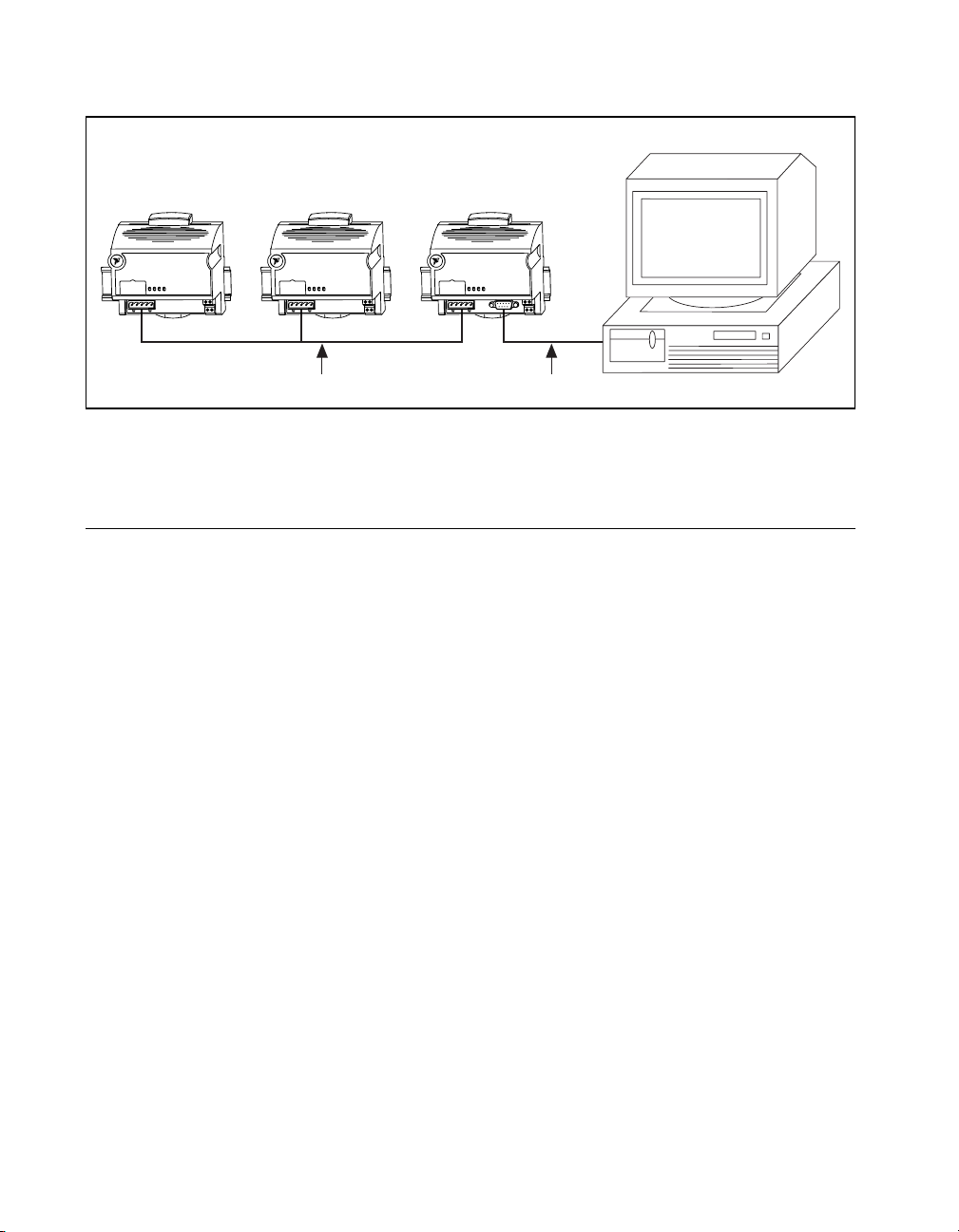
One option for connecting the FP-1001 is to connec t it to the RS-485
repeater port of an FP-10 00 as shown in Figure 2-5. A n alter nat ive
method is to connect the FP-1001 directly to your host computer, if your
host computer provid es an RS- 485 interf ace (c ontac t N atio nal
Instruments for in for ma tio n ab out a va ilab le RS -4 85 ha rdw are ). You
can connect up to 25 FP-1001 network modules to each RS-485 port on
the host computer. Th is ne twork conf iguration is shown in Fig ure 2-6.
FieldPoint FP-1000/FP-1001 User Manual 2-4
©
National Instruments Corporation
Page 16

Chapter 2 Installation and Configuration
Host Computer with
RS-485 Board Installed
FP-1001FP-1001FP-1001
RS-485
Figure 2-6. Host Computer Connected to Three FP-1001 Network Modules
The multidrop topology used in the networking configurations provides
protection against powe r fa ilures a t ind ividua l FieldPoint ban ks. I t
eliminates the possibility that a power failure at one FP-1001 bank
might affect the communication be twee n other ban ks in y our ne two rk.
Because the FP-1000 provides an RS-485 repeater, a power failure at
that bank will affe ct comm unic ation s.
Connecting to the Serial Ports
The following sections give information about the RS-232 and RS-485
ports on the network modules, and how to connect to them.
The RS-232 port on the FP- 1000 ne twork mod ule is a full-d uplex
interface. The RS-485 port o n the FP-10 00 and FP-10 01 netwo rk
modules are optically isolated , full-duple x inter faces.
Caution: The RS-485 interfac e o n bo th the FP -10 00 and the FP -1001 mod ules is
!
©
National Instruments Corporation 2-5 FieldPoint FP-1000/FP-1001 User Manual
isolated from the rest of the FieldPoint system, including the power supply,
backplane, and the RS-232 interface on the FP-1000. It is isolated with a
galvanic and optical isolation barrier, which has been designed and tested
to withstand fault voltages of up to 2500 Vrms. However, the safety rating
of this barrier is only for working voltage s of up to 2 50 Vrms . Do not use
the isolation barrier of the RS-485 interface as a way to protect human
contact from common mode voltages of more than 250 Vrms. Also note that
while the RS-232 interface on the FP-1000 is isolated from the RS-485
interface, it is NOT isolated from the power supply inputs (the V and C
terminals).
Page 17

Chapter 2 Installation and Configuration
Both serial interfaces are self-configured to use the following
parameters:
1 Start Bit, 8 Data Bits, 1 Stop Bit, No Parity
The supported ba ud ra tes ar e 30 0, 12 00, 24 00, 9 600 , 192 00, 38 400 ,
57600, and 115200. Re fer to the Configu ring the Network Module
section for informatio n about s etting the ba ud rate fo r you r m od ules.
Host computer RS-232 ports and RS-485 interface boards provide FIFO
buffers for transmit and receive that he lp to decrease the ove rhead on
host computers. Na tional I nstru ments r e comme nd s that you en ab le
these FIFO buffers in your host computer or RS-485 interface board for
best performance.
RS-232 Interface Specifications
RS-232 specifies a maximum cabling distance of 50 ft, but
improvements in line drivers and cabling technology often allow you to
design your network beyond the re co mmen dation s of the specific ation.
The RS-232 connector is 9-pin female Dsub connector whose pinout is
shown in Figure 2-7.
Legend:
NC = Not Connected
GND = Ground
RX = Recieve
Figure 2-7.
FieldPoint FP-1000/FP-1001 User Manual 2-6
GNDNCRX
54321
9876
NC
RS-232 Connector Pinout for the FP-1000
TX
NC
NC
RTS
DSR
TX = Transmit
RTS = Request to Send
DSR = Data Set Ready
©
National Instruments Corporation
Page 18

The FP-1000 does not use RS-232 hardware handshaking, but it still
asserts the RTS and DSR signals for host comp uters or s oftware that
may require thes e signals. A ho st c omp uter tha t d oe s n ot u se thes e
signals does not need to connect to them.
RS-485 Interface Specifications
RS-485 specifies a maximum cabling distance of 4000 ft, but
improvements in line drivers and cabling technology often allow you to
design your network beyond the recommendations of the specification.
If even longer distan ces ar e desira ble, y ou can use R S-48 5 rep eate rs.
An RS-485 stub is created whe n you ta p the RS-48 5 bac kbon e to form
a T-junction. RS-48 5 stubs m ust be less tha n 3 in. lo ng. H owe ver, you
can create longer stubs by using an RS-485 repeater to start the stub,
ensuring that the repeater is close to the junction.
The RS-485 connec tor is a 5-p in Co mbicon co nne ctor w ho se pinout is
shown in Figure 2-8.
RX+
RX–
Chapter 2 Installation and Configuration
TX–
GND
TX+
12345
Figure 2-8.
RS-485 Connector Pinout for the FP-1000 and FP-1001
RS-485 Network Termination and Biasing
An RS-485 network must be terminated at each end of the network, but
not anywhere else. At e a ch e nd ba nk , termina tion r es istors should be
installed between the RX pair and between the TX pair. These network
terminating resistors are nominally 120 Ω and are provided in your kit.
To install them, twist the resistor leads w ith the RS-485 signal wires and
then insert them into the RS-485 Combicon adapter as shown in
Figure 2-9. The 120 Ω resistor in the figure is a terminating resistor.
©
National Instruments Corporation 2-7 FieldPoint FP-1000/FP-1001 User Manual
Page 19
Chapter 2 Installation and Configuration
RX+
RX-
GND
TX-
TX+
RS-485
Signal Pair
+
–
120 Ω 120 Ω
Figure 2-9. Terminating RS-485 Using the Combicon Adapter
An RS-485 network also needs biasing resistors to protect the devices
on the network against noise du ring intervals when no RS- 485 drivers
are transmitting on the network. The host computer’s RS-485 interface
normally has provision for such biasing resistors. When you are using
FP-1001 network module s d ire ctly conne cted to a h ost com pu ter’s
RS-485 interface, you s hould use the biasing fe ature of the h ost
computer’s RS-485 interface for better reliability and noise immunity.
The RS-485 repeater interface on the FP-1 000 alre ady has biasing
resistors, so you do not ne ed to do an ything whe n conne cting o ne or
more FP-1001 modules to the FP- 100 0.
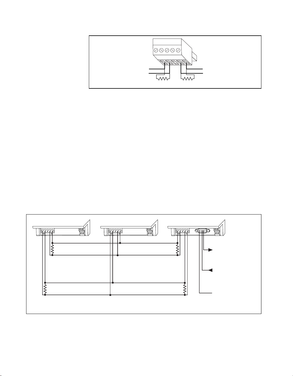
Figures 2-10 and 2-11 show typ ica l RS- 232 and RS-4 85 signal
connections and terminatio n for a FieldPoint network. Figure 2-10 is a
more detailed depiction of Figure 2-5, and Figur e 2-11 is a more
detailed depiction of Figure 2-6.
FP-1001 FP-1001 FP-1000
+
RS-485
–
Signal Pair
TX
120Ω
RX
120Ω
Connect the TX outputs of the FP-1001 to the RX inputs of the FP-1000,
and the RX inputs of the FP-1001 to the TX outputs of the FP-1000.
TX RX
RX TX
Figure 2-10. Typical Signal Connections for Host Computer Connected to One
FP-1000 and Multiple FP-1001 Network Modules
FieldPoint FP-1000/FP-1001 User Manual 2-8
120Ω
120Ω
To Host
Computer's RS-232
Receive Input
From Host
Computer's RS-232
Transmit Output
Ground
©
National Instruments Corporation
Page 20

Chapter 2 Installation and Configuration
FP-1001 FP-1001
RX TX RX TX RX TX
120Ω
120Ω
Connect the TX outputs of the host computer to the RX inputs of the FP-1001,
and the RX inputs of the host computer to the TX outputs of the FP-1001.
Figure 2-11. Typical Signal Connections for Host Computer Connected to Multiple
FP-1001 Network Modules
Configuring the Network Module
Figure 2-12 shows the 8-position switch on the FP-1000 and FP-1001
FieldPoi nt netw ork module s. Sw itche s 1-5 set the net work ad dress , and
switches 6-8 set the baud rate.
FP-1001
120Ω
120Ω
+
To Host
Computer's RS-485
–
Receive Input Pair (RX)
–
From Host
Computer's RS-485
+
Transmit Output Pair (TX)
Baud
Address
12345678
Rate
12345678
Switch Cover
(Removed)
Figure 2-12. Address and Baud Rate Switch
©
National Instruments Corporation 2-9 FieldPoint FP-1000/FP-1001 User Manual
Page 21

Chapter 2 Installation and Configuration
Follow these steps to set the address and baud rate for your network
module.
1. Choose and set a network address. Refer to the following section,
Setting the Network Address, for mor e info rmati on.
2. Choose and set the baud rate. F or mo re inf orm a tion , re fer t o th e
section, Setting the Baud Rate, later in this chapter.
3. Write your address and baud rate settings in the space provided on
the network module label.
4. Apply (or cycle) power to the bank, to enable the n etwor k module
for the new network address and baud ra te.
5. Make the same address and baud rate changes in your FieldPoint
software. Refer to the Fi el dPoint softwa re on line he lp for more
information.
Setting the Network Address
Switches 1-5 set the network module address. The a ddresses of the
terminal bases in a FieldPoint bank are automatically configured by the
network module to be sequ en tial ly h ighe r th an the n etwor k mod ule’ s
address. For example, if the network module is set to address 20, the I/O
module in the terminal base adjacent to the network module is at
address 21, the next I/O mo dule is at address 22, and so on. A terminal
base is assigned an add ress whe ther an I /O mod ule is in ser ted on it or
not.
Note: If you are connecting more than one network module to the same host
computer port, ensure that e ach ne twork module has a uniq ue addre ss.
Table 2- 1 shows the possible switch pos itions and the correspon ding
address of the FieldPoint network module.
FieldPoint FP-1000/FP-1001 User Manual 2-10
©
National Instruments Corporation
Page 22

Chapter 2 Installation and Configuration
12345678
12345678
12345678
12345678
12345678
12345678
12345678
12345678
12345678
12345678
12345678
12345678
Table 2-1. Network Address Switch Settings for the FP-1000 and FP-1001 Network Modules
Switch
Positions 1 - 5
12345678
12345678
12345678
12345678
12345678
12345678
12345678
12345678
Network Module
Address (Decimal)
0 130
10 140
20 150
30 160
40 170
50 180
60 190
70 200
Switch
Positions 1 - 5
Network Module
Address (Decimal)
12345678
90 220
80 210
12345678
100 230
12345678
110 240
12345678
120 Other Settings Not Allowed
12345678
©
National Instruments Corporation 2-11 FieldPoint FP-1000/FP-1001 User Manual
Page 23

Chapter 2 Installation and Configuration
12345678
12345678
12345678
12345678
Setting the Baud Rate
Switches 6-8 set the network module baud rate. Table 2-2 show s the
switch positions and the corresponding ne twork baud ra tes of the
network module.
Note: If you are connecting more than one network module to the same host
computer port, ensure that every network module’s baud rate setting is
identical.
Table 2-2.
Switch
Positions 6-8
Baud Rate Switch Settings for the FP-1000 and FP-1001 Network Modules
Network Module
Baud Rate
Switch
Positions 6-8
300 19200
12345678
1200 38400
12345678
2400 57600
12345678
9600 115200
12345678
Connecting Power to the FP-1000 or FP-1001
An 11-30 VDC power supp ly is re quir ed by each FieldPo int n etwork
module. The network module filters and regulates this supplied power
and provides power fo r all the I /O m odules in th e b an k. The refo re you
need not provide power separately to each FieldPoint I/O module in the
bank.
Network Module
Baud Rate
FieldPoint FP-1000/FP-1001 User Manual 2-12
The power connector is a 4-pin screw terminal connector whose pinout
is shown in Figure 2-13.
©
National Instruments Corporation
Page 24

Chapter 2 Installation and Configuration
VV
V
11-30 VDC
Figure 2-13. FP-1000 and FP-1001 Power Connector Pinout
+
-
CC
To Adjacent Terminal Base
(Optional Connection)
C
The two terminals labeled V are internally connected on the network
module, as are the two terminals labeled C. Power must be applied to
one V and C pair for operation of the FieldPoint bank. If you want to
power your field I/O devices from th e same pow er supply, the second
V and C pair provid es a conv enie nt mean s o f con necting po wer to the
V and C terminals of a term inal base. Figu re 2-13 sh ows this option al
connection.
If your field I/O devices need to be powered separately, you can use the
terminals provided on each terminal base for such power supply
connections. Refer to the documen tation that came w ith your terminal
base and I/O module for more informa tion on powe ring your field I/O
devices.
Calculating Power for a FieldPoint Bank
The power requirements fo r a Fie ldPoint ba nk that uses an FP-1000 or
FP-1001 network module a re ca lcu lated a s follow s:
Power = 1 watt + 1.15 * ∑(I/O Module Co nsump tion)
The operating instructions fo r eac h Fie ldPoint I/O m odu le cont ain
power consumption information.
©
National Instruments Corporation 2-13 FieldPoint FP-1000/FP-1001 User Manual
Page 25

Chapter
Feature Set Description
This chapter describes the fea ture se t for the FP- 1000 and FP-1 001
network modules.
Both the FP-1000 and FP-1 001 have a n identica l fea ture set, so this
chapter uses the term network module to refer to either one. Any specific
differences ar e note d.
High-Speed Local Bus
The network modules provid e a high-spee d local bus for
communication to the I/O modules in the bank. The high-speed local
bus has low overhead that enables fast response to commands from the
host computer.
Network Watchdog Timer
The network module c an d etect unexp ec ted perio ds o f ne two rk
inactivity and respond to it in a user-defined way. The network
watchdog timer feature enables you to guard your system against
failures in the network connection, cables, or host computer, and to put
the channel outputs in a user-defined state (the watchdog state) if such
failures do occur.
3
You can set the watchdog output values to be different from the
power-up output values. Some system applications do not differentiate
between power-up o utput values a nd w atchdo g o utpu t value s, wh ile
other applications treat the two conditions differently. The network
module supports both types of applications.
By default, the watchdog timer for the bank is disabled on power up. To
use the watchdog timer, set up the following parameters. You can use
either the FieldPoint Explorer software or the FieldPoint com mand se t.
• Watchdog data value for each channel.
• Watchdog data enable/disable status for each channel.
©
National Instruments Corporation 3-1 FieldPoint FP-1000/FP-1001 User Manual
Page 26

Chapter 3 Feature Set Description
• Watchdog enabled/disabled status for each I/O module.
• Watchdog timeout value for the bank.
Note: Each bank has only one watchdog timeout value that is common for all the
modules in that bank. In addition, the current watchdog timeout value is
not stored when you store the SnapShot.
SnapShot Feature
Many applications require that, upon startup, the system’s I/O power up
with user-specified configuration and outpu t levels rather than factory
default settings. The SnapShot feature pro vides y ou with a sing le-step
method to store the current state of your Fie l dPoint bank for use as the
power-up state of the ba nk.
If you subsequently e nab le the SnapSh ot f eature , you c an ens ure th at
your system will power up with the configuration and output levels that
you specified when storin g the Sna pShot.
Prior to storing the SnapShot, you should bring all the channels to the
desired power-up settings. You can use either the FieldPoint Server
software or the FieldPoint command set to change the configuration of
the FieldPoint bank, and then store the SnapShot. The SnapShot stores
all the following information in a single step:
• Attribute and range settings of each chan nel.
• Output values of each channel.
• Watchdog data values of each channel. See the Network Watchdog
• Watchdog data enabled (o r disabled ) status for each cha nnel. See
• Watchdog enabled (or disabled) status of each module. See the
Timer section in this chapter for more information.
the Network Watchdog Timer section in this chapter for more
information.
Network Watchdog Timer section in this chapter for more
information.
After you store the SnapShot information, you can still choose whether
the network module u ses that stored inf orm ation during f uture
power-ups. Enable the SnapShot feature if you want the FieldPoint bank
to power-up with the stored SnapShot information.
FieldPoint FP-1000/FP-1001 User Manual 3-2
©
National Instruments Corporation
Page 27

If you have enabled the SnapShot feature, the network module restores
the stored settings to all I/O modules and channels in the bank every
time you power up, un til you disable the Sn ap Shot fe atur e. If the
SnapShot feature is disabled, the FieldPo int bank will powe r up with
factory-default settings.
At some time you might want to change the stored SnapShot
information. To make incremental changes in the stored SnapShot
information, you can use the featur es de scribe d in the next se ction ,
Programmable Power-Up State.
Note: The current watchdog timeout value for the FieldPoint bank is not saved
when you store the SnapShot.
Note: The SnapShot feature inherently requires that the entire FieldPoint bank
be at your desired power-up state, since when you store the SnapShot
information, the current settings of the entire bank are stored for use at
future power-ups.
Programmable Power-Up State
The SnapShot feature described in the SnapShot section provides you
with a single-s tep me thod to s tore th e curr ent s tate of the F ieldP oint
bank for use a s the p ow er-u p state. Th e FieldPo i nt netw ork m odu le
provides an alternative method to define power-up states that allows
you to store the SnapShot information with more flexibility, as
described in this section.
Chapter 3 Feature Set Description
The Programmable Power -Up State feature enables you to def ine the
power-up configuration on a module-by-module basis. In addition, you
do not need to actually set any of the channels to the desired pow er- up
state. You can therefore define the power-up states regardless of the
current settings of any channel of a module.
Optionally, you can utilize the Programmable Power-Up State feature
to incrementally modify previously stored SnapShot information.
If you subsequently e nab le the Sna pShot f eat ure, yo u ca n ens ure th at
your system will power up with the configuration and output levels that
you specified when storing the Programmab le Power-Up States .
You can utilize the Programmable Power-Up State feature to
individually store the following information. Y ou can use either the
FieldPoint Explorer software or the Fiel dPoint comm and set.
©
National Instruments Corporation 3-3 FieldPoint FP-1000/FP-1001 User Manual
Page 28

Chapter 3 Feature Set Description
• Attribute and range settings of each chan nel.
• Output values of each channel.
• Watchdog data value of each channel. See the Network Watchdog
• Watchdog data enabled (o r disabled ) status for each cha nnel. See
• Watchdog timer enabled (or disabled) status of each module. See
• Power-up watchdog timeout va lue fo r th e FieldPoin t ba nk.
• The turn-around delay fo r eac h module.
• The hot-swap reporting mode for th e FieldPoint stack . See the
If you have enabled the SnapShot feature, the network module restores
your desired settings to all I/O modules and channels in the bank every
time you power up, un til you disable the Sn ap Shot fe atur e.
Timer section in this chapter for more information.
the Network Watchdog Timer section in this chapter for more
information.
the Network Watchdog Timer section in this chapter for more
information.
HotPnP section for more in forma tio n on th e ho t-sw ap repo rting
mode.
HotPnP (Hot Plug and Play)
The HotPnP feature simplifies system installation, configuration, and
maintenance. With the HotPnP feature, you c an remove or inser t I/O
modules into the FieldPoint terminal bases while power is on, even if
the system is already engaged in network activity. You do not need to
power down the entire system or even a bank to inser t, remove, or
replace I/O modules. In addition, you do not ne ed to chan ge the
operation of the host com pute r or sof tware to use the H otPnP fe atur e.
When you insert an I/O module with the power on, it is automatically
recognized, configured, and made ava ilable on the netw ork. The
following sections describe how the HotPnP fe ature work s under
different conditions.
Note: An I/O module can be hot-inserted only if an empty terminal base is already
available in the bank. You should not add or remove terminal bases w hile
power is applied to the bank.
FieldPoint FP-1000/FP-1001 User Manual 3-4
©
National Instruments Corporation
Page 29

HotPnP During Power-Up
Upon power-up, the network module automatically uploads an
electronic data sheet (EDS) from each I/O module in its bank. The
network module then configures each I/O module in the bank to factory
default settings in the module’s EDS, or stored SnapShot settings if the
SnapShot feature is enabled.
HotPnP During Operation
You may need to insert or replac e one or mo re I/O mo dules in a bank
while your system is ope rationa l (pow er is on and the network m ay or
may not be active).
Inserting New I/O Modules
When a new I/O module is inserted, the network module automatically
uploads the EDS and configures the I/O module to factor y default
settings in the module’s EDS, or to stored SnapShot settings if the
SnapShot feature is enabled. This configuration is accomplished
without any intervention from the host computer or software.
While one or more new I/O modules in a bank are being serviced by the
HotPnP feature, the other I/O mo dule s in the b ank r emain fully
operational and accessible on the network without any interruptions. As
soon as the netwo rk mo dule conf igures the new I/ O module v ia th e
HotPnP service, that I/O module becomes automatically accessible on
the network.
Chapter 3 Feature Set Description
Replacing I/O Modules
When an I/O module is r emov ed , the ne two rk mo dule doe s no t
undertake any special course of action for the bank. The host computer
(or the software executing on it) may be unaware that the I/O module is
missing, and may continue to send commands to the missing I/O
module. Each com mand re turns a n erro r r es pons e, bu t the netw ork
module remembers the c omman ds sent to the mi ssing I/O mod ule.
When a new I/O module is connected in place of the one that was
removed, the network modu le first verifie s that the r eplac eme nt I/O
module is compatible with the one that was removed. If the I/O module
is the same as, or is compatible with, the one removed, the network
module configures the replacement I/O module with its predecessor’s
configuration and output value settings. It also applies the effects of any
commands sent by the host computer while the I/O module was missing.
©
National Instruments Corporation 3-5 FieldPoint FP-1000/FP-1001 User Manual
Page 30

Chapter 3 Feature Set Description
If the replacement module is incompatible with the one that was
removed, the network module looks at the inform ation stored in the
SnapShot. If the SnapShot is enabled and the replacement module is
compatible with the information in the SnapShot, the network module
configures the replacement mod ule with the Snap Shot configu ration.
Otherwise, the network module configures the replacement module to
factory default settings.
Table 3- 1 shows how mod ules a re con figured a fter HotPnP
replacement.
Table 3-1. Module Configuration Results After HotPnP Replacement
Replacement Module
SnapShot
Feature
Replacement Module
Configuration After
HotPnP
Enabled/
Disabled
Disabled Incompatible with the
Compatible with the
removed module
removed module
Same as the configuration
of the removed module
Factory default
configuration of
replacement module
Enabled Incompatible with the
removed module but
Same as the configuration
stored in the SnapShot
compatible with the
SnapShot information
Enabled/
Disabled
Incompatible with the
removed module and
incompatible with the
Factory default
configuration of
replacement module
stored SnapShot
information
While one or more r epl acem ent I /O mo dules in the bank a re b eing
serviced by the HotPnP feature, the other I/O modules in the bank
remain fully operational and accessible on the network without any
interruptions. As soon as the network module configures a replacement
I/O module via the HotPnP servic e, tha t I /O mo dule b ecom es
automatically accessible on the network.
FieldPoint FP-1000/FP-1001 User Manual 3-6
©
National Instruments Corporation
Page 31

Power-On Self Test (POST)
The power-on self test (POST) is a test suite that the network module
performs at power up to verify its o wn o peratio nal statu s. The test is
non-invasive and therefore does not affect the operation of the network,
nor does it affect any of your field wiring connected to the terminal
bases in the bank.
If the self-test suite fails, the network module does not participate in the
network communication traffic, thereby eliminating potential conflicts
with the other banks in your network.
The network module indicates POST failure via the STATUS LED.
Refer to the next section, LED Indicators, for more information.
LED Indicators
The network module has four LE D indica tors: POWER, NETWORK,
ACCESS, and STATUS. Figures 3-1 shows th e LED s o n th e ne two rk
modules.
Chapter 3 Feature Set Description
ADDRESS BAUD
POWER
NETWORK
Figure 3-1.
ADDRESS BAUD
STATUS
ACCESS
LEDs on the FP-1000 and FP-1001
STATUS
POWER
NETWORK
ACCESS
The green POWER LED is lit while the network module is powered up.
This LED indicates that the power supply connected to the network
module is acceptable, and that the network module is supplying power
to the I/O modules.
©
National Instruments Corporation 3-7 FieldPoint FP-1000/FP-1001 User Manual
Page 32

Chapter 3 Feature Set Description
The yellow NETWORK LED is lit during transmissions from the host
computer on the network. This LED indicates that the network module
is receiving from the network, and that the communication wires to it
are not broken. The NETW OR K LED gets brighter as activity on the
network increases.
The yellow ACCESS LED flashes when th e netwo rk mo dule or any of
the I/O modules in its bank respond to the host computer. This LED
indicates that a module in the bank was addressed by a c orrectly
formatted command, and that the module is responding to that
command (either with a success or error response).
The red STATUS LED is lit when the network module detects a failure.
If STATUS is not lit, the network module has not detected a fail ure. The
network module indicates specific error conditions by flashing
STATUS a specific number of times. Table 3-2 describes the STATUS
LED flashing sequen ce s and the c or respo nding err or condition.
Table 3-2. STATUS LED Flashes and Corresponding Error Conditions
Number of
Flashes
Error Condition
0 (stays lit) The network module initialization failed.
1 The network module address switch is incorrectly
configured. Refer to the Setting the Network Address
section in Chapter 2, Installation and Configuration.
2 The network module has detected an error in the
terminal bases in the bank. Check whether there are
more than nine terminal bases (maximum allowed) in
the bank or whether removing one or more terminal
bases eliminates the error condition.
3 The network module has detected an irrecoverable
internal error.
FieldPoint FP-1000/FP-1001 User Manual 3-8
©
National Instruments Corporation
Page 33

Using the FieldPoint
Chapter
Software
This chapter describes how to use the FieldPoint hardware with various
servers and software packages.
FieldPoint Software Overview
Your FieldPoint software consists of three parts: the FieldPoint
Explorer, the FieldPoint Se rver, and a Fie ldPoint driver fo r Loo kou t.
The FieldPoint Explorer and the Fie ldPoint Serve r ar e both 32 -bit
applications that run on Windows 95 or Window s NT.
• The FieldPoint Explorer is a configuration utility for FieldPoin t
modules. The FieldPo in t E xplorer conf igur es the Fie ldPoint
hardware; the FieldPoint server, which is used with BridgeVIE W,
LabVIEW, LabWindows
Control) client software; and the FieldPoint driver for the Lookout
software package.
• The FieldPoint Server manages the communication s between the
host computer and the FieldPoint hardware. The Fiel dPoint Server
is an interface to the BridgeVIEW, LabVIEW, and
LabWindows/CVI softwa re p acka ges fro m Na tional I nstru ments.
In addition, it provides an OPC interface for other software
packages that have OPC client capability.
• The FieldPoint driver for L ookout m a nages the c ommun ica tions
between a host computer running Look out and the FieldPo int
hardware.
4
®
/CVI, and OPC (OLE fo r Proc ess
You can also choose to communicate with the FieldPoint system using
an Optomux compatible serv er , or by usin g the Fiel dPoint comm an d
set. If you use either of these methods, refer the FieldPoint FP-1000 and
FP-1001 Programmer Reference Manual. You may, however, still use
the FieldPoint Explorer to c onfigur e the Fie ldPoint d evices bef ore
running your software.
©
National Instruments Corporation 4-1 FieldPoint FP-1000/FP-1001 User Manual
Page 34

Chapter 4 Using the FieldPoint Software
Using the FieldPoint Explorer
You can use the FieldPoint Explorer to accomplish the following tasks:
• Configure the characteristics and hard ware of a FieldPo int device
network
• Configure the tag name spac e an d I/O item s o f the FieldPo int
Server
• Write and read I/O value s to a nd fro m the Field Point h ardwar e
After configuring the FieldPoint system with FieldPoint Explor er, yo u
can save the configuration in an Industri al Automation K ernel (IAK )
file (
.iak file). This file contains the configuration information
necessary for the Fi eldPo int Serve r.
The FieldPoint Explorer include s online h elp. T o ge t starte d, ru n the
FieldPoint Explorer program and select FieldPoint from the Help menu.
Using the FieldPoint Server with BridgeVIEW
To use the FieldPoint Se rve r w ith Br idge VIEW , yo u m ust expor t the
configuration information saved by the FieldPoint Explorer in an
file to the BridgeVI EW serve r c onf igur ation da ta store, the C omm on
Configuration Database (CCDB). After you have configured and tested
your FieldPoint network from FieldPoint Explorer, select Export to
Active CCDB from the File menu option to expor t the c urre nt IA K
configuration to BridgeVIEW.
.iak
Once the IAK configuration information is exported to BridgeVIEW,
you can automatically generate BridgeVIEW tags from your FieldPoint
items by launching the B ridgeVIE W Ta g Configur ation Editor an d
clicking on the Tag Wizard button.
Refer to the BridgeVIEW user manual for more information about
BridgeVIEW server configuration, the tag configuration editor, the tag
wizard, and the active CCDB files.
Note: If you edit, rename, or move your
it to the BridgeVIEW active CCDB, you must export the
configuration file again. Also, if you select another CCDB file as the active
CCDB, you must export the
selected active CCDB file.
FieldPoint FP-1000/FP-1001 User Manual 4-2
.iak configuration file af ter you export
.iak
.iak configuration file again, to the newly
©
National Instruments Corporation
Page 35

Chapter 4 Using the FieldPoint Software
Using the FieldPoint Server with LabVIEW
To use the FieldPoint se rv er f rom Lab VIEW , first config ure and te st
your FieldPoint device network from FieldPoint Explorer. After you are
satisfied with the configuration, save your
can then access name d FieldPoint item value s us ing th e La bVI EW
FieldPoint S e rver In te rf ace .
The LabVIEW FieldPo int Serve r In ter face c on sists of se ven VI s th at
are used as an interface to the FieldPoint Server, as well as example VIs
that demonstrate the use of this interface.
•The FP Open.vi and the FP Close.vi are used to open and close a
communications session to the FieldPoi nt serv er, using the
configuration information stored in an IAK file.
•The FP Create Tag.vi is used to establish a communications session
with an I/O point defined in the IAK file.
• After establishing this session, use the FP Read.vi, FP Write.vi, or
FP Advise.vi to communicate with the device.
•The FP Get Configuration Info.vi is used to read the names of
communication resources, de vices, and I/O ite ms define d in the
IAK file.
.iak configuration file. You
During the FieldPoint Server installation, these VIs are installed and
made available in the LabVIEW function palette. For more information
on how to use thes e fu nc tions o r the ex am ple V Is, r efe r to the f ile
Fplvreadme.wri that is installed with the FieldPoint Server, or refer
to the FieldPoint Server online help.
Using the FieldPoint Server with LabWindows/CVI
The LabWindows/CVI interface to the FieldPoint Server is an
instrument driver that has C functions similar to the VIs in the
LabVIEW FieldPoint Server interface. This instrument driver is
installed with the FieldPoint Serv er if La bWin dows/CVI was al read y
installed on th e comp uter .
After opening a session to the FieldPoint network using the
configuration information in a n IAK file, you m ay e ither r ead or write
data using blocking calls or using callbacks. The function pane ls for
each of these C routines includes information on how to use the
functions.
©
National Instruments Corporation 4-3 FieldPoint FP-1000/FP-1001 User Manual
Page 36

Chapter 4 Using the FieldPoint Software
Using the FieldPoint Lookout Driver
The FieldPoint Lookout driver uses the configuration information in the
IAK file created by the Fiel dPoint Ex plore r fo r its own co nfigura tio n.
The tag names used wi th the FieldPoint Look o ut dr iv er ar e th e sam e as
the names assigned using FieldPoint Explorer. There is a separate disk
in your kit that contain s the Fie ldPoint Lo okout dr iver. T his disk a lso
contains documentation for this driver in the
Using FieldPoint with Optomux Servers
The protocol used by Field Point is co mpatible wi th the Op tomu x
protocol, and you may use Optom ux serve r s to co mm unicate with the
FieldPoint system. However, O ptomux se rver s do not inc lude
provisions for setting all the configurable parameters of a FieldPoint
system (such as input ranges and power up settings ). Thus, you sho uld
use FieldPoint Explorer to set up (and optionally store using SnapShot)
the configuration of the FieldPoint hardware before using an Optomux
server.
Refer to the FieldPoint FP-1000 and FP-1001 Programmer Reference
Manual for a description of which O ptomux co mman ds a re supp orted,
and how to scale the data retu rned whe n using this p rotocol.
lkreadme.wri file.
FieldPoint FP-1000/FP-1001 User Manual 4-4
©
National Instruments Corporation
Page 37

Appendix
Specifications
This appendix describes the specifications of the FP-1000 and FP-1001
network modules.
All FieldPoint network modules undergo extensive testing for operating
under rugged environmental conditions that exist in industrial
applications. FieldPoint network modules are design ed and tested for
immunity and susceptibility, as well as for emissions.
Network
FP-1000 ............ .. .... .. .. .... ... .. .... .. .... .. .. . 1 RS -23 2 por t, 1 RS- 485
FP-1001 ............ .... ...... .... ....... .... ...... ... 1 RS-48 5 port
Baud Rates.......... ........ ....... ...... .... ...... . 300, 120 0, 2400, 9600, 19200,
Communication Parameters ................1 Start Bit, 8 Data Bits, 1 Stop
A
repeater port
38400, 57600, 115 200
(switch settable)
Bit, No Parity
Integrity..............................................Checksum
Cabling Distance from Host*
FP-1000 ........... ...... ..... ...... .... ..... 50 ft (nomina l)*
FP-1001 ....... .. .... .. ..... .. .. .... .. .... .. .4000 ft (nom inal ) *
* Refer to the RS-232 Interface Specifications and RS-485 Interface
Specifications sections in Chapter 2, Installation and
Configuration.
Maximum Termin al Base s p er Bank ...9
Maximum Number of Banks...............25
RS-232/RS-485 Interface Chips . .... .... . 15 kV ESD, Low noise and Slew
rate interface ICs
©
National Instruments Corporation A-1 FieldPoint FP-1000/FP-1001 User Manual
Page 38

Appendix A Specifications
RS-485 Isolation ................................2500 Vrms breakdown,
250 Vrms opera tiona l
Environment
Operating Tem pe rat ure....... ..... .. .. .... .. . –40° C t o +70 ° C
Storage Tempera tur e ........ .. ..... .. .... .. ... –55° C t o + 100° C
Relative Hum idi ty ............ .. ... .... .. .. .... . 5% to 9 0% n onc on dens ing
Compliance
Electrical S afe ty ... .... .. .... .. ..... .. .. .... .. ... de signe d to mee t I EC 10 10
EMI Emissions/ I mm unity........ .... .. .. ... CISP R 11
FieldPoint FP-1000/FP-1001 User Manual A-2
©
National Instruments Corporation
Page 39

Appendix
Customer Communication
For your convenience, this appendix contains forms to help you gather the information necessary to
help us solve your technical problems and a form you can use to comment on the product
documentation. When you contact us, we need th e information on the Technical Suppor t Form and the
configuration form, if your manual contains one, about your system configuration to answer your
questions as quickly as possible.
National Instruments has techn ica l assistan ce thr ou gh electronic , fa x, a nd telepho ne sys tems to
quickly provid e the informat ion you need. Our electron ic services incl ude a bullet in board ser vice,
an FTP site, a fax-on-demand system , and e-ma il support. If you have a hardware or software
problem, first try the electronic support systems. If the information available on these systems
does not answer your questions, we offer fax and telephone support through our technical support
centers, which are staffed by applica tions engine ers.
B
Electronic Services
Bulletin Board Support
National Instruments has BBS and FTP sites dedicated for 24-hour support with a collection of files
and documents to answer most common customer questions. From these sites, you can also download
the latest instrument drivers, updates, and example programs. For recorded instructions on how to use
the bulletin board and FTP services and for BBS automated information, call (512) 795-6990. You can
access these services at:
United States: (512) 794-5422
Up to 14,400 baud, 8 data bits, 1 stop bit, no parity
United Kingdom: 01635 551422
Up to 9,600 baud, 8 data bits, 1 stop bit, no parity
France: 01 48 65 15 59
Up to 9,600 baud, 8 data bits, 1 stop bit, no parity
FTP Support
To access our FTP site, log on to our Internet host, ftp.natinst.com, as anonymous and use
your Internet address, such as joesmith@anywhere.com, as your passwor d. The support files and
documents are located in the /support directories.
©
National Instruments Corporation B-1 FieldPoint FP-1000/FP-1001 User Manual
Page 40

Fax-on-Demand Support
Fax-on-Demand is a 24-hour inf ormation re trieval sys tem containing a library o f documents on a wide
range of technical information. You can access Fax-on-Demand from a touch-tone telephone at
(512) 418-1111.
E-Mail Support (currently U.S. only
You can submit technical support questions to the applications enginee ring team through e-m ail at the
Internet address listed below. Remember to include your name, address, and phone number so we can
contact you with solutions and sugg estions.
support@natinst.com
)
Telephone and Fax Support
National Instruments has branch offices all over the world. Use the list below to find the technical
support number for your country. If there is no Nat ional Instruments office in your countr y, contact the
source from which you purchased your software to obtain support.
Telephone Fax
Australia 03 9879 5166 03 9879 6277
Austria 0662 45 79 90 0 0662 45 79 90 19
Belgium 02 757 00 20 02 757 03 11
Canada (Ontario) 905 785 0085 905 785 0086
Canada (Quebec) 514 694 8521 514 694 4399
Denmark 45 76 26 00 45 76 26 02
Finland 09 725 725 11 09 725 725 55
France 01 48 14 24 24 01 48 14 24 14
Germany 089 741 31 30 089 714 60 35
Hong Kong 2645 3186 2686 8505
Israel 03 5734815 03 5734816
Italy 02 413091 02 41309215
Japan 03 5472 2970 03 5472 2977
Korea 02 596 7456 02 596 7455
Mexico 5 520 2635 5 520 3282
Netherlands 0348 433466 0348 430673
Norway 32 84 84 00 32 84 86 00
Singapore 2265886 2265887
Spain 91 640 0085 91 640 0533
Sweden 08 730 49 70 08 730 43 70
Switzerland 056 200 51 51 056 200 51 55
Taiwan 02 377 1200 02 737 4644
United Kingdom 01635 523545 01635 523154
United States 512 795 8248 512 794 5678
Page 41

FieldPoint System Configuration Form
Record the settings and revisions of your hardware and software on the line to the right of each item.
Complete a new copy of this form each time you revise your software or hardware configuration, and
use this form as a reference for your current configuration . Completing this form accurately also helps
us to answer your questions more efficiently.
Host Computer
Computer brand ________________ Model ________________ Processor __________________
Operating system (include version number ) ___________________________________________
Clock speed ______MHz RAM _____MB Display adapter __________________________
Mouse ___yes ___no Mouse type _________________________________________________
National Instruments application software product ______________________ Version _________
Other application software product ___________________________________ Version ________
National Instruments server _________________________________________ Version ________
Other installed software that may use serial ports _______________________________________
_______________________________________________________________________________
Serial adaptor (COM port or adaptor card) used ________________________________________
Configuration _________________________________________________________________
Serial driver ______________________________________________________ Version ______
Configuration _________________________________________________________________
Serial port timeout value _____________ ms
Number of FieldPoint banks _______
COM Port
Number
Baud Rate
Data Bits/Stop Bits/
Parity
Serial Hardware That
Uses This Port
TX/RX FIFOs
FieldPoint Software
List the applications and/or servers that you are using with the FieldPoint hardware ____________
_______________________________________________________________________________
Page 42

FieldPoint Banks
Please use one page per FieldPoint bank.
Network module _____________________________________ Firmware revision ____________
Address __________________________________________ Baud rate __________________
Circle the state of the following items when your problem occurs:
LEDs POWER: ON/OFF
SnapShot feature Enabled/Disabled
Watchdog timer Enabled/Disabled Timeout value ______ ms
Number of FieldPoint terminal bases ________________________________________________
Number of FieldPoint I/O modules __________________________________________________
NETWORK: ON/OFF ACCESS: ON/OFF STATUS: ON/OFF
Base
#
0 FP-1000/FP-1001 ON/OFF ON/OFF
1 ON/OFF ON/OFF
2 ON/OFF ON/OFF
3 ON/OFF ON/OFF
4 ON/OFF ON/OFF
5 ON/OFF ON/OFF
6 ON/OFF ON/OFF
7 ON/OFF ON/OFF
8 ON/OFF ON/OFF
9 ON/OFF ON/OFF
* If a terminal base is present but no module is inserted, write “none.”
Module Name*
POWER
LED
READY
LED
Module Configuration Information
Page 43

Technical Support Form
Photocopy this form and update it each time y ou make ch anges to you r software or h ardware, and use
the completed copy of this form as a reference for your current configuration. Completing this form
accurately before contacting National Instruments for technical support helps our applications
engineers answer your questions more efficiently.
If you are using any National Instruments hardware or software products related to this problem,
include the configuration forms from their user manuals. Include additional pages if necessary.
Name __________________________________________________________________________
Company _______________________________________________________________________
Address ________________________________________________________________________
_______________________________________________________________________________
Fax (___ )___________________ Phone (___ ) ________________________________________
Computer brand ________________ Model ________________ Processor___________________
Operating system (include version number)____________________________________________
Clock speed ______MHz RAM _____MB Display adapter __________________________
Mouse ___yes ___no Other adapters installed _______________________________________
Hard disk capacity _____MB Brand _____________________________________________
Instruments used _________________________________________________________________
_______________________________________________________________________________
National Instrument s hard war e produ c t mode l__________ Revision _______________ ___ ____
Configuration ___________________________________________________________________
National Instrument s sof t war e produ ct____________________________ Version ____________
Configuration ___________________________________________________________________
The problem is: __________________________________________________________________
_______________________________________________________________________________
_______________________________________________________________________________
_______________________________________________________________________________
_______________________________________________________________________________
List any error messages: ___________________________________________________________
_______________________________________________________________________________
_______________________________________________________________________________
The following steps reproduce the problem:____________________________________________
_______________________________________________________________________________
_______________________________________________________________________________
_______________________________________________________________________________
_______________________________________________________________________________
_______________________________________________________________________________
Page 44

Documentation Comment Form
National Instruments encourages you to comment on the documentation supplied with our products.
This information helps us provide quality products to meet your needs.
Title:
Edition Date:
Part Number:
Please comment on the completeness, clarity, and organization of the manual.
_______________________________________________________________________________
_______________________________________________________________________________
_______________________________________________________________________________
_______________________________________________________________________________
_______________________________________________________________________________
_______________________________________________________________________________
_______________________________________________________________________________
If you find errors in the manual, please record the page numbers and describe the errors.
_______________________________________________________________________________
_______________________________________________________________________________
_______________________________________________________________________________
_______________________________________________________________________________
_______________________________________________________________________________
_______________________________________________________________________________
_______________________________________________________________________________
FieldPoint™ FP-1000 and FP-1001 RS-232/RS-48 5 Network Modu le User Manual
July 1997
321631A-01
Thank you for your help.
Name _________________________________________________________________________
Title __________________________________________________________________________
Company _______________________________________________________________________
Address ________________________________________________________________________
_______________________________________________________________________________
Phone (___ )__________________________ Fax (___ ) _________________________________
Mail to:
Technical Publications
National Instruments Corporation National Instruments Corporation
6504 Bridge Point Parkway (512) 794-5678
Austin, TX 78730-5039
Fax to:
Technical Publications
Page 45

Prefix Meanings Value
Glossary
m- milli- 10
k- kilo- 10
M- mega- 10
–3
3
6
% percent
° degrees
0x precedes a hexadecimal number
Ω ohms
B bytes
bank The combination of one Field Point n etwor k m odule an d o ne o r m ore
terminal bases and I/O modules.
Ccelsius
DSR Data Set Ready
EDS electronic data sheet
EMI electromagnetic interference
FIFO first- in-first-out
ft feet
ggrams
HotPnP Hot Plug and Play
Hz hert z
©
National Instruments Corporation G-1 FieldPoint FP-1000/FP-1001 User Manual
Page 46

Glossary
I/O input/ou tput
IEC International Electrotechnical Commission
in. inches
LED Light-emitting diode
OPC OLE for Process C ontrol
POST power-on self test
RAM random-access memory
RTS Request to Send
VVolts
VDC Volts direct current
FieldPoint FP-1000/FP-1001 User Manual G-2
©
National Instruments Corporation
Page 47

Index
A
ACCESS LED, 3-7
addresses, setting
address and baud rate, 2-9 to 2-10
network address, 2-10 to 2-11
unique address for each module (note), 2-10
B
banks. See FieldPoint banks.
baud rate
address and baud rate switch settings
(figure), 2-9
baud rate switch settings (figure), 2-12
setting for network module, 2-9 to 2-10
biasing resistors for RS-485 port, 2-8
BridgeVIEW software, using with FieldPoint
Server, 4-2
bulletin board support, B-1
bus, high-speed local, 3-1
C
configuration of network module, 2-9 to 2-12.
See also installation.
address and baud rate selection, 2-9 to 2-10
baud rate settings, 2-12
network address settings, 2-10 to 2-11
connections
network connections
FP-1000, 2-3 to 2-4
FP-1001, 2-4 to 2-5
serial port connections, 2-5 to 2-9
isolation of RS-485 interface (note),
2-5 to 2-6
RS-232 interface specifications,
2-6 to 2-7
RS-485 interface specifications,
2-7 to 2-9
terminal base connection, 2-2 to 2-3
connector pinouts
power connector (figure), 2-13
RS-232 ports (figure), 2-6
RS-485 ports (figure), 2-7
customer communication, B-1 to B-2, xi
D
DIN rail clip
installing network module (figure), 2-1
locking FieldPoint network module
(figure), 2-2
unlocked position (figure), 2-1
documentation
conventions used in manual, x-xi
how to use manual set, ix
organization of manual, x
related documentation, xi
E
electronic support services, B-1 to B-2
e-mail support, B-2
environment specifications, A-2
error conditions indicated by STATUS LED
(table), 3-8
© National Instruments Corporation I-1 FieldPoint FP-1000/FP-1001 User Manual
Page 48

Index
F
fax and telephone support, B-2
fax-on-demand support, B-2
feature set description, 3-1 to 3-8
high-speed local bus, 3-1
HotPnP (Hot Plug and Play), 3-4 to 3-6
LED indicators, 3-7 to 3-8
network watchdog timer, 3-1 to 3-2
power-on self test (POST), 3-6 to 3-7
Programmable Power-Up State, 3-3 to 3-4
SnapShot feature, 3-2 to 3-3
FieldPoint banks
calculating power for bank, 2-13
maximum number of banks, 1-1
network watchdog timer, 3-1 to 3-2
SnapShot feature, 3-2 to 3-3
FieldPoint network modul es. See als o feature
set description.
overview, 1 -1
specifications, A-1 to A-2
FieldPoint software, 4-1 to 4-4
FieldPoint Explorer, 4-2
FieldPoint Lookout driver, 4-4
Optomux Servers, 4-4
overview, 4 -1
using FieldPoin t Server
with BridgeVIEW, 4-2
with LabVIEW, 4-3
with LabWindows/CVI, 4-3
FP-1000
connecting to network, 2-3 to 2-4
connection to RS-232 port, 1-1
power connections, 2-12 to 2-13
FP-1001
connecting to network, 2-4 to 2-5
connection to RS-485 port, 1-2
power connections, 2-12 to 2-13
FTP support, B-1
H
HotPnP (Hot Plug and Play), 3-4 to 3-6
inserting new I/O modules, 3-5
module configuration results after
HotPnP replacement (table), 3-6
during operation, 3-5 to 3-6
overview, 3-4
during power-up, 3-4
replacing I/O modules, 3-5 to 3-6
I
installation, 2-1 to 2-13. See also configura-
tion of network module.
connecting to network
FP-1000, 2-3 to 2-4
FP-1001, 2-4 to 2-5
HotPnP (Hot Plug and Play) features,
3-4 to 3-6
network module installation, 2-1 to 2-2
power connections for FP-1000 or
FP-1001, 2-12 to 2-13
calculating power for FieldPoint
bank, 2-13
removing network module, 2-2
serial port connections, 2-5 to 2-9
isolation of RS-485 interface (note),
2-5 to 2-6
RS-232 interface specifications,
2-6 to 2-7
RS-485 interface specifications,
2-7 to 2-9
terminal base connection, 2-2 to 2-3
I/O modules
inserting new, 3-5
module configuration results after
HotPnP replacement (table), 3-6
replacing, 3-5 to 3-6
FieldPoint FP-1000/FP-1001 User Manual I-2 © National Instruments Corporation
Page 49

Index
L
LabVIEW software, using with FieldPoint
Server, 4-3
LabWindows/CVI software, using with
FieldPoint Server, 4-3
LED indicators, 3-7 to 3-8
local bus, high-speed, 3-1
M
manual. See documentation.
N
network address, setting, 2-10 to 2-11
NETWORK LED, 3-7
network module. See FieldPoint network
modules.
network termination and biasing, RS-485
ports, 2-7 to 2-9
network watchdog timer, 3-1 to 3-2
O
Optomux protocol, 1-1
Optomux Servers, using with FieldPoint
software, 4-4
P
pinouts. See connector pinouts.
power connections, 2-12 to 2-13
calculating power for FieldPoint
bank, 2-13
pinout (figure), 2-13
POWER LED, 3-7
power-on self test (POST), 3-6 to 3-7
Programmable Power-Up State, 3-3 to 3- 4
R
removing FieldPoint network module, 2-2
RS-232 ports
connector pinout (figure), 2-6
FP-1000 connection to, 1-1
interface specifications, 2-6 to 2-7
self-configuration parameters, 2-6
RS-485 ports
Combicon adapter for termination
(figure), 2-8
connector pinout (figure), 2-7
FP-1001 connection to, 1-2
interface specifications, 2-7 to 2-9
isolation from FieldPoint system
(note), 2-5
network termination and biasing,
2-7 to 2-9
self-configuration parameters, 2-6
typical signal connections (figures),
2-8 to 2-9
S
serial ports. See RS-232 ports; RS-485 ports.
SnapShot feature, 3-2 to 3-3
software. See FieldPoint software.
specifications, A-1 to A-2
compliance, A-2
environment, A-2
network, A-1 to A-2
STATUS LED, 3-8
switches
address and baud rate switch (figure), 2-9
baud rate switch settings (figure), 2-12
network address switch settings
(figure), 2-11
© National Instruments Corporation I-3 FieldPoint FP-1000/FP-1001 User Manual
Page 50

Index
T
technical support, B-1 to B-2
telephone and fax support, B-2
terminal base connection, 2-2 to 2-3
termination and biasing, RS-485 ports,
2-7 to 2-9
W
watchdog timer, 3-1 to 3-2
FieldPoint FP-1000/FP-1001 User Manual I-4 © National Instruments Corporation
 Loading...