

National Instruments FieldPoint FP-TB-1, FieldPoint FP-TB-3, FieldPoint FP-TB-2 Operating Instructions Manual
Page 1

Artisan Technology Group is your source for quality
new and certied-used/pre-owned equipment
• FAST SHIPPING AND
DELIVERY
• TENS OF THOUSANDS OF
IN-STOCK ITEMS
• EQUIPMENT DEMOS
• HUNDREDS OF
MANUFACTURERS
SUPPORTED
• LEASING/MONTHLY
RENTALS
• ITAR CERTIFIED
SECURE ASSET SOLUTIONS
SERVICE CENTER REPAIRS
Experienced engineers and technicians on staff
at our full-service, in-house repair center
Instra
Remotely inspect equipment before purchasing with
our interactive website at www.instraview.com
Contact us: (888) 88-SOURCE | sales@artisantg.com | www.artisantg.com
SM
REMOTE INSPECTION
View
WE BUY USED EQUIPMENT
Sell your excess, underutilized, and idle used equipment
We also offer credit for buy-backs and trade-ins
www.artisantg.com/WeBuyEquipment
LOOKING FOR MORE INFORMATION?
Visit us on the web at www.artisantg.com for more
information on price quotations, drivers, technical
specications, manuals, and documentation
Page 2

FieldPoint Operating Instructions
FP-TB-1/2/3
FieldPoint Terminal Bases
These operating instructions describe the installation, features,
and characteristics of the FP-TB-1, FP-TB-2, and FP-TB-3.
Features
The FP-TB-1, FP-TB-2, and FP-TB-3 are FieldPoint terminal
bases with the following features:
• Works with all FieldPoint I/O modules (the FP-TB-3 is
designed specifically to work with thermocouple I/O modules)
• V andC terminals provideexternal supply voltages common to
all channels
• DIN-rail mounting or panel mounting
• 32 terminals available for field connections (FP-TB-3 has 16)
• Available with screw terminals (FP-TB-1 and FP-TB-3) or
spring terminals (FP-TB-2)
• Isothermal construction (FP-TB-3) minimizes temperature
gradients when using thermocouples
• –40 to 70 °C operation
The FP-TB-1, FP-TB-2, and FP-TB-3 terminal bases provide the
intra-system communication link between FieldPoint I/O modules
and network modules, provide a means for wiring field
connections, and provide the mounting mechanism. You can
choose your terminal base depending on the type of field wiring
terminal you prefer: screw terminal or spring terminal.
FieldPoint™, National Instruments™, NI™, and ni.com™ aretrademarks of National Instruments Corporation.
Product and company names mentioned herein are trademarks or trade names of their respective companies.
For patents coveringNational Instrumentsproducts, refer tothe appropriate location:
patents.txt
the
321699E-01 May 2002
©
1999–2002 National Instruments Corp. All rights reserved.
Artisan Technology Group - Quality Instrumentation ... Guaranteed | (888) 88-SOURCE | www.artisantg.com
file on your CD, or
ni.com/patents
.
Help»Patents
in yoursoftware,
Page 3
MountingtheFP-TB-1/2/3onaDINRail
Caution
To avoid damaging the network module and
terminal base, make sure that power is not applied to the
network module while you are installing or removing a
terminal base.
FieldPoint terminal bases have simple rail clips for reliable
mounting on a standard 35 mm DIN rail. Follow these steps to
mount the terminal base on a DIN rail.
1. Write down the serial number, located on the back of the
terminal base, before you mount it on the DIN rail.
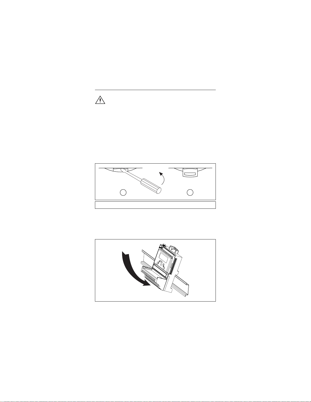
2. Use a flathead screwdriver to open the DIN rail clip to the
unlocked position, as shown in Figure 1.
1 2
1 Rail clip locked 2 Rail clip unlocked
Figure 1. Unlocking the Rail Clip
3. Attach the lip on the rear of the terminal base onto the top of a
35 mm DIN rail and press it down onto the DIN rail, as shown
in Figure 2.
Figure 2. Attaching the Terminal Base to a DIN Rail
FP-TB-1/2/3 Operating Instructions 2 ni.com
Artisan Technology Group - Quality Instrumentation ... Guaranteed | (888) 88-SOURCE | www.artisantg.com
Page 4
4. Slide the terminal base along the DIN rail until its local bus
connector mates with the connector of the terminal base or
network module adjacent to it.
5. After the terminal base is in position, lock it to the DIN rail by
pushing the rail clip to the locked position.
6. To add more terminal bases, install them on the rail and
connect their local bus connectors together.
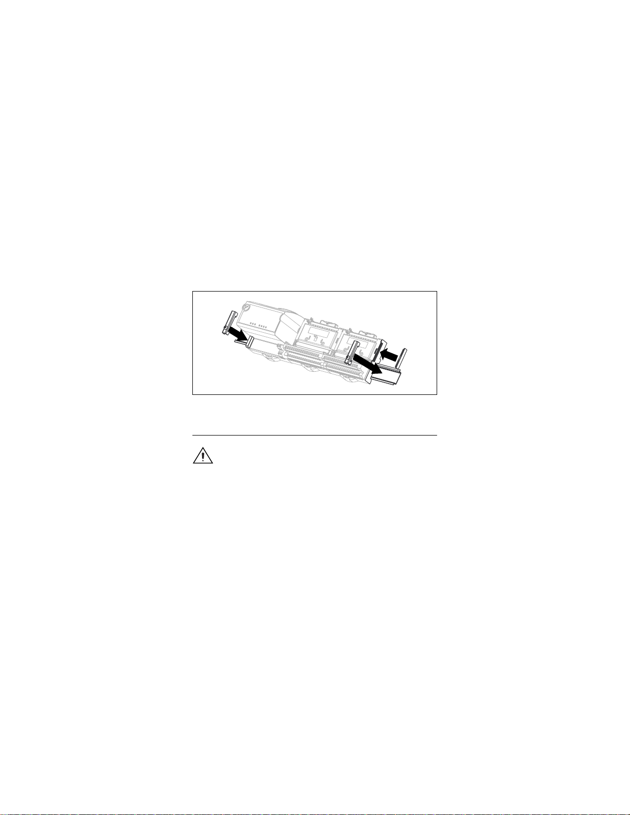
7. Place the protective cover onto the local bus connector of the
last terminal base on the bank, as shown in Figure 3. Add rail
locks by sliding them on and tightening the screws.
Figure 3. Adding Rail Locks and Protective Cover
Mounting the FP-TB-1/2/3 to a Panel
Caution
To avoid damaging the network module and
terminal base, make sure that power is not applied to the
network module while you are installing or removing a
terminal base.
Follow these steps to mount the terminal base on a wall or panel.
1. Use Figure 4 to locate where to drill the mounting holes on the
panel. Dimensions are given in millimeters [inches].
© National Instruments Corp. 3 FP-TB-1/2/3 Operating Instructions
Artisan Technology Group - Quality Instrumentation ... Guaranteed | (888) 88-SOURCE | www.artisantg.com
Page 5
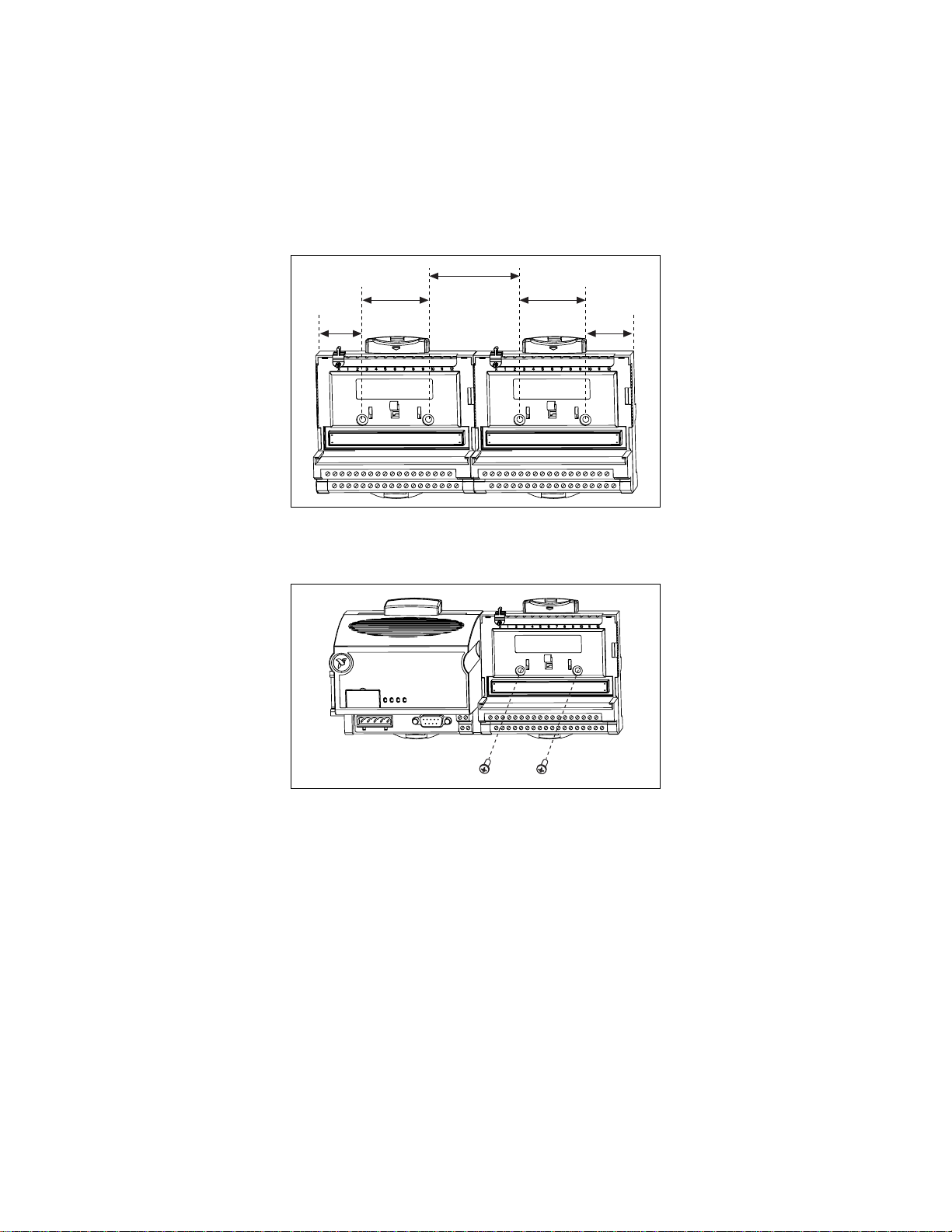
62.48 [2.46]
31.24
[1.23]
44.64 [1.76]
44.64 [1.76]
31.24
[1.23]
Figure 4. Locating the Mounting Holes
2. When you have located and drilled the mounting holes, mount
the terminal base as shown in Figure 5.
Figure 5. Mounting the Terminal Base
3. Place the protective cover over the local bus connector of the
last terminal base in the bank.
FP-TB-1/2/3 Operating Instructions 4 ni.com
Artisan Technology Group - Quality Instrumentation ... Guaranteed | (888) 88-SOURCE | www.artisantg.com
Page 6
Mounting I/O Modules
on the Terminal Base
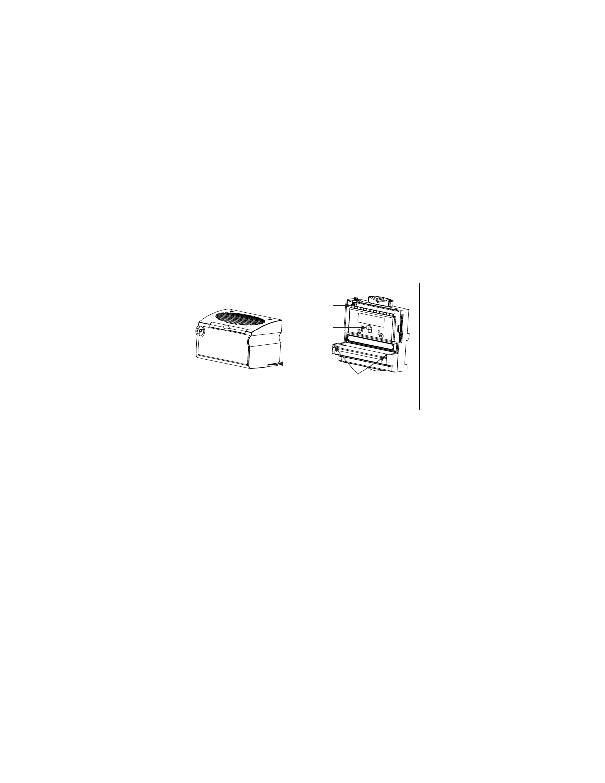
Refer to Figure 6 and follow these steps to install an I/O module on
the terminal base.
1. Slide the terminal base key to the appropriate position for the
I/O module. The position marked X is a universal position that
works for all modules.
2. Align the alignment slots on the I/O module with the guide
rails on the terminal base.
Key
Latch
Alignment
Slot
Guide Rails
Terminal BaseI/O Module
Figure 6. Mounting the I/O Module on the Terminal Base
3. Press firmly to seat the I/O module on the terminal base. When
the module is firmly seated, the terminalbase latch locks it into
place and the ejector button on the top of the terminal base
pops up.
4. To remove an I/O module, press the ejector button on top of the
terminal base and pull off the module.
© National Instruments Corp. 5 FP-TB-1/2/3 Operating Instructions
Artisan Technology Group - Quality Instrumentation ... Guaranteed | (888) 88-SOURCE | www.artisantg.com
Page 7

Field Wiring
The FP-TB-1 and FP-TB-2 provide four dedicated terminals and
32 numbered terminals defined by the I/O module. The terminals
are designed for 16–26 AWG copper conductor wire with 7 mm
(0.28 in.) of insulation stripped from the end as shown in Figure 7.
Use only copper wire unless you are working with a sensing
device, such as a thermocouple, that requires a different kind
of wire.
7mm
Figure 7. Conductor Wire with the Correct Strip Length
The four dedicated terminals are two V and two C terminals, one
of each at both ends of the terminal base. The two V terminals
are internally connected by the terminal base, as are the two
C terminals. Generally, these terminals are intended to connect
external power supplies to field devices. FieldPoint I/O modules
get their power from the network module through the backplane,
and in most cases require no external power for proper operation.
Refer to the appropriate I/O module operating instructions
for details on the use of these terminals and the other 32 terminals.
The FP-TB-3 provides two dedicatedC terminals and 16 numbered
terminals defined by the I/O module. Although the FP-TB-3 is
designed specifically to work with thermocouple modules, I/O
modules that do not require external power and that only use
terminals 1 to 16 can be used with the FP-TB-3.
Caution
make sure that power is not applied to it.
Before you connect wires to the terminal base,
Connecting Wires to the FP-TB-1 or FP-TB-3
Follow these steps to connect wires to the FP-TB-1 or FP-TB-3.
1. Loosen the terminal screw you want to wire.
2. Insert the wire in the terminal.
3. Tighten the screw terminal to 0.5–0.6 N ⋅ m (4.4–5.3 lb ⋅ in.) of
torque.
FP-TB-1/2/3 Operating Instructions 6 ni.com
Artisan Technology Group - Quality Instrumentation ... Guaranteed | (888) 88-SOURCE | www.artisantg.com
Page 8

Connecting Wires to the FP-TB-2
Follow these steps to connect wires to the FP-TB-2.
1. Insert a screwdriver into the slot directly below the terminal
number and push the screwdriver downward into the slot. You
may need to push hard. This forces the spring-loaded terminal
to open.
2. Insert the wire in the terminal.
3. Withdraw the screwdriver, allowing the spring terminal to
clamp securely onto the wire.
V12345678910111213141516V
C17181920212223242526272829303132C
Figure 8. Connecting Wires to the Spring Terminals of the FP-TB-2
© National Instruments Corp. 7 FP-TB-1/2/3 Operating Instructions
Artisan Technology Group - Quality Instrumentation ... Guaranteed | (888) 88-SOURCE | www.artisantg.com
Page 9

Powering the FieldPoint System
Consider the following points when connecting power to the
FieldPoint system.
• The total current flowing through the V and C terminals must
be limited to 10 A. If you have a single external supply for the
field devices of more than one module, wire the supply to the
V and C terminals as shown in Figure 9.
1
2
1 When total current draw is
less than 10 A
Figure 9. Connecting Power for Current Draws Below and Above 10 A
Caution
Cascading power from neighboring bases or
2 When total current draw is
greater than 10 A
network modules defeats isolation between cascaded
modules.
• When total current draw is less than 3 A, you can use a single
terminal for the return path. If the total current draw is greater
than 3 A, you should use separate C terminals, as shown in
Figure 10.
FP-TB-1/2/3 Operating Instructions 8 ni.com
Artisan Technology Group - Quality Instrumentation ... Guaranteed | (888) 88-SOURCE | www.artisantg.com
Page 10

1
2
1 When total current draw is
lessthan3A
2 When total current draw is
greater than 3 A
Figure 10. Connecting Power for Current Draws Below and Above 3 A
• You need to wire power to the terminal bases only if you want
to use the terminal bases to route power to field devices or if
the I/O module requires it. FieldPoint I/O modules get their
power from the network module through the backplane and,
in most cases, require no external power for proper operation.
Refer to your I/O module operating instructions for details. In
Figure 11, shades of gray indicate differing voltage potentials.
FP-TC-120 FP-AO-200FP-AI-110
Figure 11. Different Voltage Potentials
Caution
Cascading power from neighboring bases or
Live (V)
Ground
Neutral (C)
FP-RLY-420
network modules defeats isolation between cascaded
modules.
• You may want to use separate power supplies for I/O modules
both to prevent power dips caused by field devices from
disrupting the operation of the networkmodule and tomaintain
© National Instruments Corp. 9 FP-TB-1/2/3 Operating Instructions
Artisan Technology Group - Quality Instrumentation ... Guaranteed | (888) 88-SOURCE | www.artisantg.com
Page 11

the isolation barrier between the I/O modules and the network
module. Figure 12 shows an example configuration with both
separate power supplies and cascading power.
FP-TC-120 FP-RLY-420FP-AO-200FP-AI-110
1
2
Thermocouple
(self powered)
17
V
sup
4-20 mA
Figure 12. Example Power Supply Configuration for a FieldPoint Bank
V
COM
IN
2
I
IN
–+
±5V
1 18 Common
Channel 0
2
18
Caution
Cascading power from neighboring bases or
network modules defeats isolation between cascaded
modules.
Thermocouple Wiring
The FP-TC-120 thermocouple input module has the ability to
measure the temperature of the terminals on any of the FieldPoint
terminal bases. This measurement is called the cold junction
temperature and indicates the temperature of the junctions
between your thermocouple wire and the screw terminals. This
measurement is used internally by the FP-TC-120 to correct for
the thermoelectric voltages that are generated at these junctions.
Heat dissipated by adjacent modules (or other nearby heat sources)
can cause errors in thermocouple measurements by heating up the
terminals so that they are at a different temperature than the sensor
used to measure the cold junction. The thermal gradient generated
across the terminals can cause the terminals of different channels
FP-TB-1/2/3 Operating Instructions 10 ni.com
Artisan Technology Group - Quality Instrumentation ... Guaranteed | (888) 88-SOURCE | www.artisantg.com
Page 12

to be at different temperatures, and so the resulting measurement
creates not only errors in absolute accuracy but also in the relative
accuracy between channels. The accuracy specifications for the
FP-TC-120 include the errors caused by a 0.2 °C (0.36 °F)
gradient. The actual gradient you can expect to encounter depends
on the terminal base you use and the details of your installation.
The following sections provide guidelines for estimating and
minimizing thermal gradients.
Estimating Thermal Gradients with the FP-TB-3
Isothermal Terminal Base
The FP-TB-3 is designed with isothermal construction to keep
the terminals at the same temperature. It is the terminal
base recommended for the best accuracy of thermocouple
measurements. Adjacent FieldPoint modules (either network
modules or I/O modules) create a thermal gradient across the
terminals of the FP-TB-3, which you can estimate by dividing
the larger of the amounts of heat dissipated by each of the adjacent
modules by 20 W/°C(11W/°F). For example, if the FP-TB-3 is
between an analog input module dissipating 0.35 W and a discrete
output module dissipating 3 W, the thermal gradient would be
3W÷ 20 W/ °C = 0.15 °C.
Estimating Thermal Gradients with the FP-TB-1
or FP-TB-2 Terminal Bases
The lack of isothermal construction in the FP-TB-1 and FP-TB-2
terminal bases makes them more susceptible to errors caused by
thermal gradients. These terminal bases are recommended for use
with thermocouple measurements only if such errors are
acceptable or if they can be minimized, as described in the
Minimizing Thermal Gradients section. Adjacent FieldPoint
modules (either network modules or I/O modules) create a thermal
gradient across the terminals of the FP-TB-1, which you can
estimate by dividing the larger of the amounts of heat dissipated by
each of the adjacent modules by 1 W/°C (0.6 W/°F). For example,
if the FP-TB-1/2 is between an analog input module dissipating
0.35 W and a discrete output module dissipating 3 W, the thermal
gradient would be 3 W ÷ 1W/°C=3°C. The typical thermal
gradient created by the FP-TC-120 mounted on an FP-TB-1
(neglecting any adjacent modules) is about 0.2 °C.
© National Instruments Corp. 11 FP-TB-1/2/3 Operating Instructions
Artisan Technology Group - Quality Instrumentation ... Guaranteed | (888) 88-SOURCE | www.artisantg.com
Page 13

Minimizing Thermal Gradients
The most common source of thermal gradients, particularly for the
FP-TB-1 and FP-TB-2, is the heat generated by adjacent modules.
For example, placing an FP-TB-1 next to an FP-1000 network
module can create more than a 1 °C thermal gradient. Mounted
thermocouple modules can be separated from the higher-power
modules by the lowest-power modules in your system or by the
FieldPoint Bus Extender Cable (part number 185576-15). This
precaution is generally not necessary with the FP-TB-3.
Hot or cold air draft can be another source of thermal gradients.
It is usually best to avoid having air blowing directly on the
terminals, although circulating air around other nearby
components may help them dissipate their heat and cause them
to be less of a source of thermal gradients on the terminal base.
Thermocouple wire also has the potential to be a significant source
of thermal gradients. Even the FP-TB-3 can be susceptible to these
errors. Heat or cold may be directly conducted to the terminal
junction by the thermocouple wire. If the thermocouple wires,
or objects they are in contact with, such as wiring ducts, near the
terminal base are at a different temperature than the terminals,
the wires transfer heat to or from the terminals and cause thermal
errors. To minimize these errors, follow these guidelines:
• Use small-gauge thermocouple wire. Smaller wires transfer
less heat.
• Run thermocouple wires together near the terminal base to
keep them at the same temperature.
• Avoid running thermocouple wires near hot or cold objects.
Specifications
The following specifications are typical for a range of
–40 to 70 °C, unless otherwise noted.
Installation
Terminal wiring ................................ 16–26 AWG copper
conductor wire with 7 mm
(0.28 in.) of insulation
stripped from the end
1
Use only copper conductor wire unless you are working with a sensing
device, such as a thermocouple, that requires a different kind of wire.
FP-TB-1/2/3 Operating Instructions 12 ni.com
1
Artisan Technology Group - Quality Instrumentation ... Guaranteed | (888) 88-SOURCE | www.artisantg.com
Page 14

Torque for screw terminals ............... 0.5–0.6 N ⋅ m
(4.4–5.3 lb ⋅ in.)
Physical
Weight
FP-TB-1...................................... 210 g (7.4 oz)
FP-TB-2...................................... 160 g (5.7 oz)
FP-TB-3...................................... 240 g (8.5 oz)
Maximum Working Voltage
Maximum working voltage refers to the signal voltage plus the
common-mode voltage.
Channel-to-earth ............................... 250 V, Installation
Category II
Channel-to-channel........................... See I/O module operating
instructions
1
Caution
Improper wiring may defeat isolation barrier.
Environmental
FieldPoint modules are intended for indoor use only.
Operating temperature ...................... –40 to 70 °C
Storage temperature ..........................–55 to 85 °C
Humidity ...........................................10 to 90% RH,
noncondensing
Maximum altitude............................. 2,000 m
Pollution degree ................................2
Safety
The FP-TB-1/2/3 meets the requirements of the following
standards for safety and electrical equipment for measurement,
control, and laboratory use:
• EN 61010-1:1993/A2:1995, IEC 61010-1:1990/A2:1995
• UL 3121:1998
• CAN/CSA c22.2 no. 1010.1:1992/A2:1997
1
May vary by I/O module. See I/O module operating instructions.
© National Instruments Corp. 13 FP-TB-1/2/3 Operating Instructions
Artisan Technology Group - Quality Instrumentation ... Guaranteed | (888) 88-SOURCE | www.artisantg.com
Page 15

Electromagnetic Compatibility
CE, C-Tick and FCC Part 15 (Class A) Compliant
Electrical emissions .......................... EN 55011 Class A at 10 m
FCC Part 15A above 1 GHz
Electrical immunity ..........................Evaluated to EN 61326:
1997/A1: 1998, Table 1
For full EMC compliance, you must operate this
Note
device with shielded cabling. See the Declaration of
Conformity (DoC) for this product for any additional
regulatory compliance information. To obtain the DoC
for this product, click Declaration of Conformity at
ni.com/hardref.nsf/
.
Mechanical Dimensions
Figure 13 show the mechanical dimensions of the FP-TB-1/2/3
with an I/O module installed. Dimensions are given in millimeters
[inches].
107.19 [4.22]
109.5
[4.31]
91.44 [3.60]
Figure 13. Mechanical Dimensions
Where to Go for Support
For more information about setting up your FieldPoint system,
refer to these National Instruments documents:
• Your FieldPoint network module user manual
• Your other FieldPoint I/O module operating instructions
• Your FieldPoint terminal base operating instructions
Go to
ni.com/support
and troubleshooting information.
FP-TB-1/2/3 Operating Instructions 14 ni.com
for the most current manuals, examples,
Artisan Technology Group - Quality Instrumentation ... Guaranteed | (888) 88-SOURCE | www.artisantg.com
Page 16

For telephone support in the United States, create your service
request at
ni.com/ask
and follow the calling instructions or dial
512 795 8248. For telephone support outside the United States,
contact your local branch office:
Australia 03 9879 5166, Austria 0662 45 79 90 0, Belgium 02 757 00 20,
Brazil 011 3262 3599, Canada (Calgary) 403 274 9391,
Canada (Montreal) 514 288 5722, Canada (Ottawa) 613 233 5949,
Canada (Québec) 514 694 8521, Canada (Toronto) 905 785 0085,
China (Shanghai) 021 6555 7838, China (ShenZhen) 0755 3904939,
Czech Republic 02 2423 5774, Denmark 45 76 26 00,
Finland 09 725 725 11, France 01 48 14 24 24, Germany 089 741 31 30,
Greece 30 1 42 96 427, Hong Kong 2645 3186, India 91 80 4190000,
Israel 03 6393737, Italy 02 413091, Japan 03 5472 2970,
Korea 02 3451 3400, Malaysia 603 9596711, Mexico 001 800 010 0793,
Netherlands 0348 433466, New Zealand 09 914 0488,
Norway 32 27 73 00, Poland 0 22 3390 150, Portugal 351 210 311 210,
Russia 095 238 7139, Singapore 6 2265886, Slovenia 386 3 425 4200,
South Africa 11 805 8197, Spain 91 640 0085, Sweden 08 587 895 00,
Switzerland 056 200 51 51, Taiwan 02 2528 7227,
United Kingdom 01635 523545
© National Instruments Corp. 15 FP-TB-1/2/3 Operating Instructions
Artisan Technology Group - Quality Instrumentation ... Guaranteed | (888) 88-SOURCE | www.artisantg.com
Page 17

Artisan Technology Group is your source for quality
new and certied-used/pre-owned equipment
• FAST SHIPPING AND
DELIVERY
• TENS OF THOUSANDS OF
IN-STOCK ITEMS
• EQUIPMENT DEMOS
• HUNDREDS OF
MANUFACTURERS
SUPPORTED
• LEASING/MONTHLY
RENTALS
• ITAR CERTIFIED
SECURE ASSET SOLUTIONS
SERVICE CENTER REPAIRS
Experienced engineers and technicians on staff
at our full-service, in-house repair center
Instra
Remotely inspect equipment before purchasing with
our interactive website at www.instraview.com
Contact us: (888) 88-SOURCE | sales@artisantg.com | www.artisantg.com
SM
REMOTE INSPECTION
View
WE BUY USED EQUIPMENT
Sell your excess, underutilized, and idle used equipment
We also offer credit for buy-backs and trade-ins
www.artisantg.com/WeBuyEquipment
LOOKING FOR MORE INFORMATION?
Visit us on the web at www.artisantg.com for more
information on price quotations, drivers, technical
specications, manuals, and documentation
 Loading...