

Page 1

OPERATING INSTRUCTIONS
FP-PWM-520
8-Channel, 5 or 24 V PWM
Output Module
These operating instructions describe the installation, features, and
characteristics of the FP-PWM-520. For details on configuring
and accessing the FP-PWM-520 over a network, refer to the user
manual for the particular FieldPoint network module you are using
with the FP-PWM-520.
Features
The FP-PWM-520 is a FieldPoint pulse-width modulated (PWM)
output module with the following features:
• Eight PWM output channels
• 0 to 100% duty-cycle capability with 12-bit resolution
• One millisecond period resolution
• Overcurrent protected outputs
• Sourcing outputs compatible with sinking inputs or 24 VDC
devices
• On/off LED indicators
• Hot plug and play operation
• 3,000 Vrms input-to-output isolation
• Double insulated for 250 V safe working voltage
• Independent configuration of the output period for each
channel from 1 to 65,535 ms in 1 ms increments
FieldPoint ™ is a trademark of National Instruments Corporation. Product and company names
mentioned herein are trademarks or trade names of their respective companies.
322139B-01 © Copyright 1998, 1999 National Instruments Corp. All rights reserved. June 1999
Page 2

Installation
The FP-PWM-520 mounts on a FieldPoint terminal base
(FP-TB-xx) unit. Because of its hot plug and play operation, you
can install the FP-PWM-520 onto a powered terminal base without
disturbing the operation of other modules or terminal bases. The
FP-PWM-520 receives operating power from the terminal base.
To install your module, refer to Figure 1 and complete the
following steps:
1. Slide the terminal base key to either position X (used for any
module) or position 4 (used for the FP-PWM-520 module).
2. Align the FP-PWM-520 alignment slots with the guide rails on
the terminal base.
3. Press firmly to seat the FP-PWM-520 on the terminal base.
When the module is firmly seated, the terminal base latch locks
it into place.
Key
Latch
Alignment
Slot
Guide Rails
Terminal BaseI/O Module
Figure 1.
Install Your Module
Field Wiring
The terminal base provides connections for each of the eight output
channels and for an external supply to power f i eld devices.
Although the module does not need the external supply for its
internal operation, the output channels source current from this
external supply and require it to operate.
Each channel has one output terminal, V
terminals, COM (internally connected to the C terminal); and a
supply terminal, V
(internally connected to the V terminal).
sup
If you want to connect an external supply to power field devices,
connect to the V and C terminals of the terminal base, or to the V
FP-PWM-520 2 www.natinst.com
; two common
out
sup
Page 3
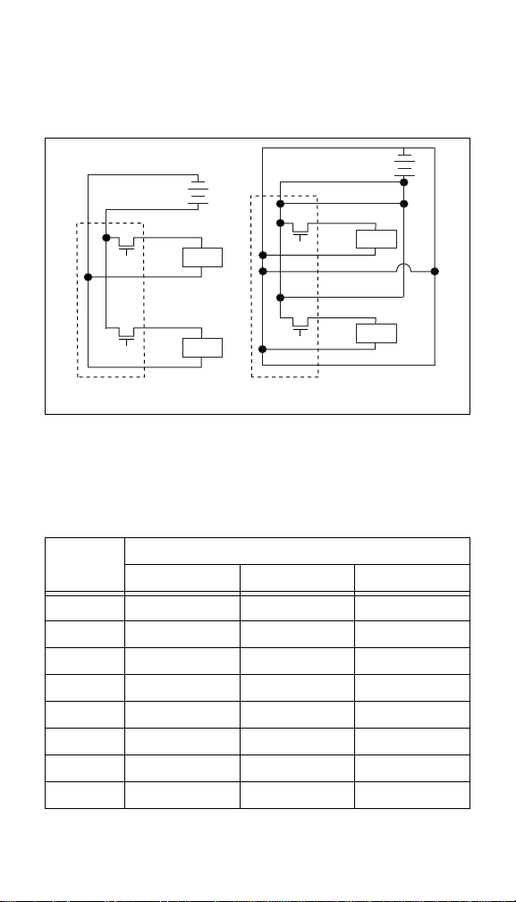
and COM terminals for the individual channels. If the total current
supplied by the FP-PWM-520 channels is more than 4 A, route the
external supply to the V
and COM terminals. Otherwise, you can
sup
connect the external supply only to the V and C terminals. Figure 2
shows two examples of basic wiring connections.
–
CV
a. Total Current Less
Than 4 Amps
Figure 2.
–
V
out
COM
V
out
COM
CV
+
Load
Load
V
sup
V
out
COM
COM
V
sup
V
out
COM
COM
b. Total Current Greater
Than 4 Amps
Basic Field Connections (Two Channels Shown)
+
Load
Load
Table 1 lists the terminal assignments for the signals of each
channel. T erminal assignments and wiring diagrams are also listed
under the slide-in card on the front of the FP-PWM-520 module.
Table 1.
Terminal Assignments
Terminal Numbers
Channel
V
out
V
sup
COM
0 1 17 2, 18
1 3 19 4, 20
2 5 21 6, 22
3 7 23 8, 24
4 9 25 10, 26
5 11 27 12, 28
6 13 29 14, 30
7 15 31 16, 32
© National Instruments Corp. 3 FP-PWM-520
Page 4

Pulse-Width Modulated Output Circuit
The FP-PWM-520 PWM output channels have optically isolated
sourcing outputs with overcurrent protection circuitry. In the ON
state of the output period, a transistor is turned on between the
positive external supply v oltage (the V and V
output (V
) terminal. In the OFF state, this transistor is turned off,
out
allowing only a small leakage current to flow . Select the impedance
of the loads driven by the output channels so that the current
supplied by any one channel in the ON state is no more than 1 A.
The output channels need an external power supply of 5 VDC
or between 10 and 30 VDC connected to the C and V terminals
of the module.
In the ON state, the effective resistance between the output and the
external supply voltage is 0.3 Ω, which causes a voltage drop.
For example, if the external supply voltage is 5 V and the output
current is 1 A, the output voltage is 4.7 V:
[5 V – (1 A x 0.3 Ω)=4.7V].
Figure 3 shows a diagram of the discrete output circuit of one
channel.
terminals) and the
sup
Optical
Isolation
Figure 3.
V
C
Discrete Output Circuit
V
sup
V
out
COM
Overcurrent Protection
Overcurrent protection circuitry on each output deactiva tes the
output if the current it sources to the V
level. This level is always at least 1 A. A slightly higher inrush
current that exists for a short time will not trigger the protection
circuitry. If the protectio n circuitry disables an output that would
otherwise be in the ON state, the status indicator for that channel is
still lit, but the output transistor is turned off.
FP-PWM-520 4 www.natinst.com
terminal exceeds a safe
out
Page 5

Detecting an Overcurrent Condition
To determine whether an overcurrent condition exists, complete
the following steps:
1. Use the FieldPoint Explorer to set the duty cycle to 100% for
the channel in question.
2. Measure the voltage between the V
and COM terminals for
out
that channel.
Under normal load conditions, the V
-to-COM voltage is
out
within 1 V of the supply voltage when the output is on
continuously. Any voltage more than 1 V less than the supply
voltage indicates an overcurrent condition. Typically, the
V
-to-COM voltage is nearly zero if the protection circuitry
out
is activated.
The overcurrent protection circuitry resets when the output
switches to the OFF state, when you disconnect field power from
the module, when you remove the FP-PWM-520 from its terminal
base, or when you turn off the network module. Unless you set the
output duty cycle to 0% or 100%, the output channel switches to
the OFF state once per output period during normal operation.
Remedying an Overcurrent Condition
To remedy an overcurrent condition, determine the cause of the
overcurrent condition and disconnect the load that is causing the
problem from the FP-PWM-520. The channel resets automatically
when the load is removed.
Alternatively, if completely removing the channel load is not
convenient, reset the channel in any of the following ways:
• Use the FieldPoint Explorer to set the duty cycle to any value
other than 100% and wait at least one output period for the
channel to reset.
• Use the FieldPoint Explorer to set the duty cycle to 0%.
The channel resets immediately.
• Disconnect the external power supply from the module.
• Remove the FP-PWM-520 from the terminal base.
• Turn off the network module that the FP-PWM-520 is
connected to.
Normal operation can resume after you correct the overcurrent
condition.
© National Instruments Corp. 5 FP-PWM-520
Page 6

Output Channel Operation
Each of the PWM output channels uses a period and a duty cycle
setting to determine when to switch its output to the ON or OFF
state.
The output period is the only configuration attribute for each
channel. You can set the period to any value between 1 ms (1 kHz)
and 65,535 ms (0.01525 Hz), in increments of 1 ms.
The output duty cycle is written as the data v alue for each channel.
Y ou can set the duty cycle to any percentage v alue between 0% and
100%, with 12-bit resolution (4,096 discrete duty-cycle settings).
Status Indicators
Figure 4 shows the module label and status indicators. To see
wiring diagrams for the input channels, remove the slide-in card.
Figure 4.
After you insert the module into a terminal base (and app ly power),
the green POWER indicator lights and the FP-PWM-520 informs
the network module of its presence. When the network module
recognizes the FP-PWM-520, it sends initial configuration
information to the FP-PWM-520. After receiving this initial
information, the green READY indicator lights and the
FP-PWM-520 is in its normal operating mode. In addition to the
green POWER and READY indicators, each channel has a
numbered, green, output state indicator that lights when the
channel is in the ON state.
FP-PWM-520 6 www.natinst.com
Status Indicators and Module Label
Page 7

Isolation and Safety Guidelines
Caution
Before you connect any circuits that may
contain hazardous voltages to the FP-PWM-520, read
the following information.
This section describes the isolation of the FP-PWM-520 and its
compliance with international safety standards. The outputs are
isolated from the backplane provided by the terminal base with an
optical isolation barrier designed and tested to provide protection
against fault voltages of up to 3,000 Vrms. In addition, the
FP-PWM-520 provides double insulation (compliant with UL and
IEC safety standards) for working common-mode voltages of
250 Vrms. Safety standards (such as those published by UL and
IEC) require the use of double insulation between hazardous
voltages and any human-accessible parts or circuits.
Never try to use any isolation product between human-accessible
parts (such as DIN rails or monitoring stations) and circuits that
may be at hazardous potentials under normal conditions, unless the
product is specifically designed for such an application, as is the
FP-PWM-520.
When you use a product like the FP-PWM-520 in applications with
hazardous potentials, follow these guidelines to make sure your
total system is safe:
• The safety isolation of the FP-PWM-520 is from input to
output, not between channels on the same module. If an y of the
channels on a module are wired at a hazardous potential, make
sure that all other devices or circuits connected to that mo dule
are properly insulated from human contact.
•Do not share the e xternal supply voltages (V, C, V
, and COM
sup
terminals on the terminal base) with other devices (including
other FieldPoint devices), unless those devices are isolated
from human contact.
• As with any hazardous voltage wiring, make sure that all
wiring and connections meet with applicable electrical codes
and common sense practices. Mount terminal bases in an area,
position, or cabinet that prevents accidental or unauthorized
access to wiring that carries hazardous voltages.
• The isolation of the FP-PWM-520 is certified as
double-insulated for normal operating voltages of 250 Vrms.
Do not use the FP-PWM-520 as the only isolating barrier
between human contact and working voltages of more than
250 Vrms.
© National Instruments Corp. 7 FP-PWM-520
Page 8

Specifications
The following specifications are typical for a range –40 to +70 °C,
unless otherwise noted.
Output
Number of channels..........................8
Output type .......................................24 VDC, sourcing
Supply voltage..................................5 VDC or 10 to 30 VDC,
user-provided
Output current...................................1 A, with built-in overcurrent
Output impedance.............................0.3 Ω
Pulse-width accuracy........................–1, +3 µs, any period and
Physical
Indicators ..........................................Green POWER and
Weight...............................................140 g (4.8 oz.)
Power Requirements
Power from network module............300 mW
protection circuitry,
8 A maximum for all
channels
duty cycle
READY indicators, 8 green
output state indicators
Environment
Operating temperature......................–40 to +70 °C
Storage temperature..........................–55 to +85 °C
Relative humidity..............................5% to 90%, non-condensing
CE Mark Compliance
This product meets applicable EU directive(s), as follows:
Safety isolation .................................EN 61010 (double insulation
FP-PWM-520 8 www.natinst.com
for 250 Vrms working
isolation, installation
category II)
Page 9

EMC directive
Immunity.................................... EN 50082-1:1994
Emissions ................................... EN 55011:1991 Group I
Class A at 10 m
Mechanical Dimensions
Figure 5 shows the mechanical dimensions of the FP-PWM-520
installed on a terminal base. Dimensions are given in inches
[millimeters].
4.22 [107.19]
4.31
[109.5]
3.60 [91.44]
Figure 5.
© National Instruments Corp. 9 FP-PWM-520
Mechanical Dimensions
Page 10

 Loading...