

Page 1

OPERATING INSTRUCTIONS
FP-DI-301
8-Channel, 24 V Discrete Input Module
These operating instructions describe the installation, features, and
characteristics of the FP-DI-301. For details on configuring and
accessing the FP-DI-301 over a network, refer to the user manual
for the particular FieldPoint network module you are using with
the FP-DI-301.
Features
The FP-DI-301 is a FieldPoint discrete input module with the
following features:
• 16 discrete input channels
• Sinking inputs, compatible with 24 VDC sourcing outputs
• On/Off LED indicators
• Hot plug and play operation
• 3,000 V input to output isolation
• Double insulated for 250 V safe working voltage
• –40 to +70 °C operation
Installation
The FP-DI-301 mounts on a FieldPoint terminal base (FP-TB-xx)
unit. The hot plug and play operation of the FP-DI-301 allows you
to install it onto a powered terminal base without disturbing
the operation of other modules or terminal bases. The FP-DI-301
receives operating po wer from the terminal base.
FieldPoint ™ is a trademark of National Instruments Corporation. Product and company names
mentioned herein are trademarks or trade names of their respective companies.
321700B-01 © Copyright 1997, 1999 National Instruments Corp. All rights reserved. June 1999
Page 2

To install the FP-DI-301, refer to Figure 1 and follow these steps:
1. Slide the terminal base key to either position X (used for any
module) or position 5 (used for the FP-DI-301 module).
2. Align the FP-DI-301 alignment slots with the guide rails on the
terminal base.
3. Press firmly to seat the FP-DI-301 on the terminal base. The
terminal base latch locks the FP-DI-301 into place when it is
firmly seated.
Key
Latch
Alignment
Slot
Guide Rails
Terminal BaseI/O Module
Figure 1. Module Installation Diagram
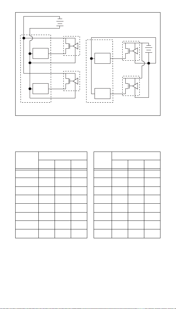
Field Wiring
The terminal base provides connections for each of the 16 input
channels and an external supply to power field devices. Each
channel can be wired for use with a sourcing output device.
Figures 2a and 2b show examples of these basic wiring
connections. The connection of an external supply to power field
devices is made to the V and C terminals of the terminal base. Each
channel has one input terminal, V
common terminals, COM (internally connected to the C terminal)
and eight supply terminals, V
V terminal).
. In addition, there are eight
in
(internally connected to the
sup
FP-DI-301 2 www.natinst.com
Page 3
VC
Input
Circuitry
Input
Circuitry
V
sup
V
in
COM
V
sup
V
in
COM
+
–
C
Input
Circuitry
Input
Circuitry
V
in
V
in
+
–
a. Three-Wire Sourcing Outputs
Powered from FP-DI-301
Figure 2.
Basic Field Connections to Sourcing Output Devices
b. Externally Powered
Sourcing Outputs
Table 1 lists the terminal assignments for the signals associated
with each channel.
Table 1.
Terminal Numbers
Channel
VinV
0 1 17 18 8 9 25 26
1 2 17 18 9 10 25 26
2 3 19 20 10 11 27 28
3 4 19 20 11 12 27 28
4 5 21 22 12 13 29 30
5 6 21 22 13 14 29 30
6 7 23 24 14 15 31 32
7 8 23 24 15 16 31 32
Terminal Assignments
COM VinV
sup
Channel
Terminal Numbers
sup
COM
© National Instruments Corp. 3 FP-DI-301
Page 4

Discrete Input Circuit
The inputs of the FP-DI-301 consist of optical isolators with
current-limiting resistors. Each channel has one signal input, V
in
which is referenced to the common, COM. When a voltage above
the threshold voltage is applied to the Vin input of a channel, signal
current flows through the input and turns on the optical isolator,
registering as an ON condition. The threshold voltage is typically
10 V, but may be as low as 5 V or as high as 15 V.
The FP-DI-301 has sinking inputs, which means that the inputs
sink current from the V
terminal to the common COM terminal.
in
This makes the inputs compatible with sourcing output devices
capable of sourcing or driving current from a positive supply
voltage to common. The FP-DO-400 and FP-DO-401 are examples
for sourcing output devices.
Figure 2 shows connections to sourcing output devices. These
devices should have OFF state leakage currents of less than 1 mA
to ensure that they do not provide false ON state readings to the
FP-DI-301.
Status Indicators
Figure 3 shows the module label and status indicators. You can
remove the insertable label to see wiring diagrams for the input
channels.
,
Figure 3.
Status Indicators
After the module has been inserted into a terminal base (and
power is applied), the green POWER indicator turns on and the
FP-DI-301 informs the network module of its presence. When
the network module recognizes the FP-DI-301, it sends initial
FP-DI-301 4 www.natinst.com
Page 5

configuration information to the FP-DI-301. After receiving, this
READY indicator turns on and the FP-DI-301 is in its normal
operating mode. In addition to the green POWER and READY
indicators, each channel has a numbered green status indicator
which lights when the channel is in the ON state.
Isolation and Safety Guidelines
Caution
Read the following information before
attempting to connect ANY circuits which may contain
hazardous voltages to the FP-DI-301.
This section describes the isolation of the FP-DI-301 and its
compliance with international safety standards. The field wiring
connections of the FP-DI-301 are isolated from the
backplane
provided by the terminal base with an optical and galvanic isolation
barrier designed and tested to provide protection against fault
voltages of up to 3000 Vrms. In addition, the FP-DI-301 pro vides
double insulation (compliant to IEC 1010-1) for working common
mode voltages of 250 Vrms. Safety standards (such as those
published by UL and IEC) require the use of double insulation
between hazardous voltages and any human-accessible parts or
circuits. You should never attempt to use any isolation product
between human accessible parts (such as DIN rails or monitoring
stations) and circuits which may be at hazardous potentials under
normal conditions, unless the product is specifically designed (as
the FP-DI-301 is) for such an application.
Even when a product like the FP-DI-301 is used in applications
with hazardous potentials, follow these guidelines to ensure a safe
total system.
• The safety isolation of the FP-DI-301 is from input to output,
not between channels on the same module. If any of the
channels on a module are wired at a hazardous potential,
ensure that all other devices or circuits connected to that
module are properly insulated from human contact.
•Do not share the external supply voltages (V and C on the
terminal base) with other devices (including other FieldPoint
devices) unless those devices are also isolated from human
contact.
• As with any hazardous voltage wiring, ensure that all wiring
and connections meet with applicable electrical codes or
common sense practices. Mount terminal bases in an area,
© National Instruments Corp. 5 FP-DI-301
Page 6

position, or cabinet that prevents accidental or unauthorized
access to wiring with hazardous voltages.
• The isolation of the FP-DI-301 is certified as double insulated
for normal operating voltages of 250 Vrms. Do not use the
FP-DI-301 as the sole isolating barrier between human contact
and working voltages of more than 250 Vrms.
Specifications
These specifications are typical for the range –40 to +70 °C unless
otherwise noted.
Input Characteristics
Number of channels..........................16
Input type..........................................24 VDC sinking inputs
Maximum input voltage....................30 VDC
Input threshold level .........................10 VDC typical
5 VDC minimum
15 VDC maximum
Input impedance................................5 kOhm
Input delay times...............................1 ms
Isolation ............................................3,000 Vrms
Safety isolation, working voltage .....250 Vrms, designed per IEC
1010 as double insulated
Physical
Indicators ..........................................Green POWER and
READY indicators, 16 green
input state indicators
Weight...............................................130 g (4.5 oz.)
Power Requirements
Power from network module............325 mW
Environment
Operating temperature......................–40 to +70 °C
Storage temperature..........................–55 to +100 °C
Relative humidity..............................5% to 90% non-condensing
FP-DI-301 6 www.natinst.com
Page 7

CE Mark Compliance
This product meets applicable EU directive(s) as follows:
Safety isolation .................................EN 61010 (double insulation
for 250 Vrms working
isolation, installation
category II)
EMC directive
Immunity.................................... EN 50082-1:1994
Emissions ...................................EN 55011:1991 Group I
Class A at 10 meters
Mechanical Dimensions
Figure 4 shows the mechanical dimensions of the FP-DI-301
installed onto a terminal base. Dimensions are given in inches
[millimeters].
4.22 [107.19]
4.31
[109.5]
3.60 [91.44]
Figure 4.
© National Instruments Corp. 7 FP-DI-301
Mechanical Dimensions
Page 8

 Loading...