

Page 1

FP-AO-200
8 Channel, 20 mA Loop Output Module
Highlights
• Eight 0-20/4-20 mA outputs
• 0.5 mA over-range ability
• 12-bit resolution DACs
• Open current loop indicators
• 3,000 V input-to-output isolation
• Double insulated for 250 V safe working voltage
• Up to 1 kOhm load impedance (with 24 V loop supply)
• Short circuit protection
• -40° to +70° C operation
Overview
The FP-AO-200 is a FieldPoint analog output module with eight
0-20/4-20 mA current loop outputs. You can use the FP-AO-200 to
drive devices using process current loops of either the 0-20 mA or
4-20 mA standards. Hot plug and play operation, safety isolation,
onboard diagnostics such as open loop detection, and over-ranging
ability ensure that installation and maintenance are as trouble free
as possible.
These operating instructions describe the installation, features, and
characteristics of the FP-AO-200. For details on configuring and
accessing the FP-AO-200 over a network, refer to the user manual
for the particular FieldPoint network module you are using with the
FP-AO-200.
FieldPoint ™ is a trademark of National Instruments Corporation. Product and company names are
trademarks or trade names of their respective companies.
321634A-01
©
Copyright 1997 National Instruments Corp. All rights reserved. July 1997
Page 2
Module Installation
The FP-AO-200 mounts on a FieldPoint terminal base (FP-TB-xx)
unit. The hot plug and play operation of the FP-AO-200 allows you
to install it onto a powered terminal base without disturbing the
operation of other modules or terminal bases. The FP-AO-200
receives operating power from the terminal base. Current loop
power is externally supplied.
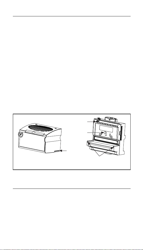
To install the FP-AO-200, refer to Figure 1 and follow these steps:
1. Slide the terminal base key to either position X (used for any
module) or position 2 (used for the FP-AO-200 module).
2. Align the FP-AO-200 alignment slots with the guide rails on
the terminal base.
3. Press firmly to seat the FP-AO-200 in the terminal base. The
terminal base latch locks the FP-AO-200 into place when it is
firmly seated.
4. Connect a current loop supply for the outputs to the V and C
terminals of the terminal base.
Key
Latch
Alignment
Slot
Guide Rails
Terminal BaseI/O Module
Figure 1.
Module Installation Diagram
Field Wiring
The FP-AO-200 sources current from an external loop supply to a
load (or field device). The terminal base provides connections for
both the external loop supply and for the eight output channels.
Figures 2a and 2b show examples of these basic wiring
connections. The positive terminal of the loop supply is connected
to the V terminal; the negative (or common) terminal is connected
to the C terminal. Each channel has an output terminal, I
common terminal, COM (internally connected to the C terminal);
2
out
; a
Page 3
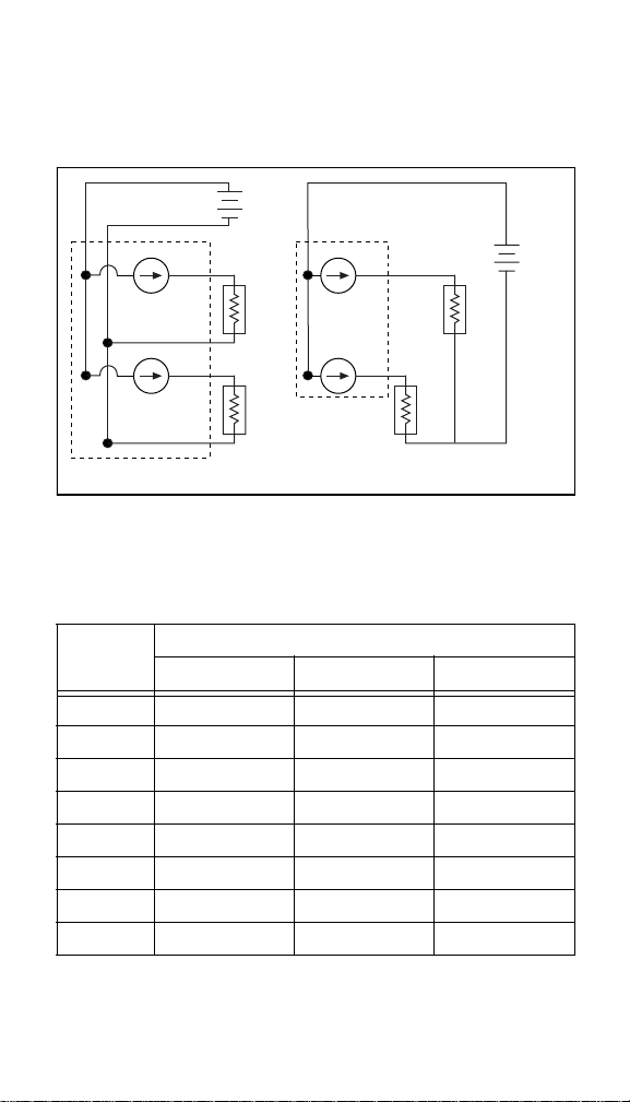
and a supply terminal, V
terminal). As the figures show, connections to the C and COM
(internally connected to the V
sup
terminals are not required but may be used to simplify wiring. You
may use connections to the V
V terminal to devices which require supplementary power.
VC
I
out
terminals to route power from the
sup
Loop
Supply
V
I
out
Loop
Supply
Load
COM
I
out
Load
COM
a. With COM Connection b. Without COM Connection
I
out
Load
Load
Figure 2. Basic Field Connections (Two channels shown)
Table 1 lists the terminal assignments for the signals associated
with each channel.
Table 1. Terminal Assignments
Terminal Numbers
Channel
I
out
0 1 2, 18 17
1 3 4, 20 19
2 5 6, 22 21
3 7 8, 24 23
4 9 10, 26 25
5 11 12, 28 27
6 13 14, 30 29
7 15 16, 32 31
COM V
sup
3
Page 4
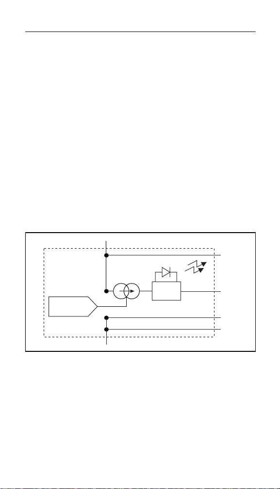
Current Output Circuit
The output circuit of the FP-AO-200 is a sourcing current output,
which means that it is designed to source current provided by an
external loop supply to a device or load capable of sinking this
current to the common voltage of the loop supply. The FP-AO-200
can operate with an external loop supply from 5 to 24 VDC;
however, this voltage dictates the maximum load impedance which
the FP-AO-200 can drive. With a 24 VDC loop supply, each output
can drive up to 1 kOhm of load impedance. With a 5 VDC loop
supply, each output can only drive up to 100 Ohms. The
FP-AO-200 detects and reports error conditions due to excessive
loads or insufficient loop supplies. For more information, refer to
the Open Loop Detection section in this document.
The FP-AO-200 updates the output channels as new values are sent
to it by the network module. The time it takes to respond to a
change on a single channel is between 3 and 6 ms. The response
time to changes on all eight channels is 24 to 27 ms.
Figure 3 shows a diagram of the current output circuit of a single
channel.
V
V
sup
Open Loop
Indicator
12-Bit
Isolated DAC
Current
Sense
C
I
out
COM
COM
Figure 3.
FA-A0-200 Current Output Circuit
The FP-AO-200 has several unique features that promote reliable
operation, ease of use, and solid performance. These features are
described below.
4
Page 5

Output Ranges
You may configure the output range of each channel independently
for either 0-20 mA or 4-20 mA operation. The factory default
power-up setting for each channel is 0-20 mA, with output set to
0 mA. The FP-AO-200 has a built in over-range capability of
0.5 mA in each of these ranges, thus the actual full scale ranges
available are 0-20.5 mA and 3.5-20.5 mA. This extended range
feature allows the FP-AO-200 to compensate for span and offset
errors in field devices.
Open Loop Detection
Each channel has a monitoring circuit which compares the actual
output current to the desired output current. If the FP-AO-200
cannot source the desired output current for one or more channels,
these monitoring circuits turn on a red STATUS LED for each
affected channel and report this error condition to the network
module. Generally, the cause for this error condition is an open
current loop—either the load device or the loop supply is
disconnected. However, this method or detection also catches
errors caused by a load impedance that is too high, or a loop supply
voltage that is too low, to provide the desired output current.
If the output of the an FP-AO-200 channel is set to 0 mA, the
monitoring circuit does not register an error condition because the
FP-AO-200 can always source zero current, even to an open loop.
So, if any channels are unused and left unwired they should be left
in the default state of 0 mA to prevent unnecessary (and possibly
annoying) error indications.
Short Circuit Protection
Each output terminal I
short circuits to any of the other terminals. One or more channel
outputs can be short circuited indefinitely without causing damage
or improper operation of other channels, as long as the maximum
loop supply does not exceed 24 VDC. The outputs can withstand
indefinite short circuits with loop supplies of more than 24 VDC
(up to 36 VDC) without damage, but increasing internal
temperatures due to such conditions may cause improper operation
of other channels on the module.
of the FP-AO-200 is protected against
out
5
Page 6

Status Indicators
Figure 4 shows the module label and status indicators. You can
remove the insertable label to see wiring diagrams for the output
channels.
Figure 4. Status Indicators
After the module has been inserted into a terminal base (and power
is applied), the module runs an internal boot up sequence and self
test. If this test passes, the green POWER indicator turns on and
the FP-AO-200 informs the network module of its presence. When
the network module recognizes the FP-AO-200, it sends initial
configuration information to the FP-AO-200. After processing this
initial information, the green READY indicator turns on and the
FP-AO-200 is in its normal operating mode. In addition to the
green POWER and READY indicators, each channel has a red,
numbered, error status indicator. For more information, refer to
the section on Open Loop Detection in this document.
Isolation and Safety
CAUTION: Read the following information before
!
attempting to connect ANY circuits which may contain
hazardous voltages to the FP-AO-200.
This section describes the isolation of the FP-AO-200 and its
compliance with international safety standards.
The field wiring connections of the FP-AO-200 are isolated from
the backplane provided by the terminal base with an optical and
galvanic isolation barrier designed and tested to provide protection
against fault voltages of up to 3000 Vrms. In addition, the
6
Page 7

FP-AO-200 provides double insulation (compliant to IEC 1010-1)
for working common mode voltages of 250 Vrms. Safety standards
(such as those published by UL and IEC) require the use of double
insulation between hazardous voltages and any human-accessible
parts or circuits. You should never attempt to use any isolation
product between human accessible parts (such as DIN rails or
monitoring stations) and circuits which may be at hazardous
potentials under normal conditions, unless the product is
specifically designed (as the FP-AO-200 is) for such an
application.
Even when a product like the FP-AO-200 is used in applications
with hazardous potentials, follow these guidelines to ensure a safe
total system.
• The isolation of the FP-AO-200 is from input to output, not
between channels on the same module. If any of the channels
on a module are wired at a hazardous potential, ensure that all
other devices or circuits connected to that module are properly
insulated from human contact.
• Do not share the external loop supply voltages (V and C on the
terminal base) with other devices (including other FieldPoint
devices) unless those devices are also isolated from human
contact.
• As with any hazardous voltage wiring, ensure that all wiring
and connections meet with applicable electrical codes or
common sense practices. Mount terminal bases in an area,
position, or cabinet that prevents accidental or unauthorized
access to wiring with hazardous voltages.
• The isolation of the FP-AO-200 is certified as double insulated
for normal operating voltages of 250 Vrms. Do not use the
FP-AO-200 as the sole isolating barrier between human
contact and working voltages of more than 250 Vrms.
7
Page 8

Specifications
These specifications are typical for -40° to +70° C unless otherwise
noted.
Output Characteristics
Number of channels .........................8 single-ended
Resolution ........................................12 bits, 1 in 4,096
Isolation ............................................3,000 Vrms, input to output
Safety isolation, working voltage.....250 Vrms channel to earth
Current Output
Output Range....................................0-20 mA or 4-20 mA,
Type..................................................Current source, external loop
External Loop Power........................5 to 24 VDC
Resistive load....................................up to 1 kOhm with 24 V
Voltage Drop ....................................3 V
Protection..........................................Short-circuit and
Default Power-on state .....................0 mA
Accuracy
Absolute accuracy.............................0.2% FSR
Monotonicity ....................................Guaranteed over temperature
Offset temperature coefficient.......... 50 nA/°C
Gain temperature coefficient ............40 ppm/°C
Dynamic Characteristics
Max conversion rate .........................200 Updates/s
Slew rate ..........................................0.4 mA/µs
(~6 µA/bit)
ground, designed per
IEC 1010
programmable (0-21 mA or
3.5-21 mA with over-range)
power required
loop supply, up to 100 Ohm
with 5 V supply
open-circuit
8
Page 9

Physical
Indicators ..........................................Green POWER and
READY indicators, 8 red
open loop indicators
Weight...............................................140 g (4.8 oz.)
Power Requirements
Power from network module............350 mW
Environment
Operating Temperature.....................-40 °C to +70 °C
Storage Temperature.........................-55 °C to + 100 °C
Relative Humidity.............................5% to 90% noncondensing
CE Mark Compliance
This product meets applicable EU directive(s) as follows:
Safety isolation ................................EN 61010 (double insulation
for 250 Vrms working
isolation, installation
category II)
EMC Directive
Immunity.................................... EN 50082-1:1994
Emissions .................................. EN 55011:1991 Group I
Class A at 10 meters
Mechanical Dimensions
Figure 5 shows the mechanical dimensions of the FP-AO-200
installed onto a terminal base.
4.31
[109.5]
3.58 [90.9]
Figure 5.
4.19 [106.4]
Mechanical Dimensions
9
Page 10

Page 11

Page 12

 Loading...