

National Instruments FieldPoint FP-2000, FieldPoint FP-2015, FieldPoint FP-2010 User Manual
Page 1

FieldPoint
FP-2000/2010/2015 User Manual
FP-2000/2010/2015 User Manual
TM
Note to Users
The contents of this document that refer to FieldPoint software are
not intended for use with FieldPoint Software 4.0 or LabVIEW 7.0.
Refer to the Measurement & Automation Explorer Help for
FieldPoint and the FieldPoint LabVIEW Interface Help.
Part Number 370705A-01
April 2003 Edition
Page 2

Support
Worldwide Technical Support and Product Information
ni.com
National Instruments Corporate Headquarters
11500 North Mopac Expressway Austin, Texas 78759-3504 USA Tel: 512 683 0100
Worldwide Offices
Australia 02 612 9672 8846, Austria 43 0 662 45 79 90 0, Belgium 32 0 2 757 00 20, Brazil 55 11 3262 3599,
Canada (Calgary) 403 274 9391, Canada (Montreal) 514 288 5722, Canada (Ottawa) 613 233 5949,
Canada (Québec) 514 694 8521, Canada (Toronto) 905 785 0085, Canada (Vancouver) 514 685 7530,
China 86 21 6555 7838, Czech Republic 420 2 2423 5774, Denmark 45 45 76 26 00,
Finland 385 0 9 725 725 11, France 33 0 1 48 14 24 24, Germany 49 0 89 741 31 30, Greece 30 2 10 42 96 427,
India 91 80 51190000, Israel 972 0 3 6393737, Italy 39 02 413091, Japan 81 3 5472 2970,
Korea 82 02 3451 3400, Malaysia 603 9131 0918, Mexico 001 800 010 0793, Netherlands 31 0 348 433 466,
New Zealand 64 09 914 0488, Norway 47 0 32 27 73 00, Poland 48 0 22 3390 150, Portugal 351 210 311 210,
Russia 7 095 238 7139, Singapore 65 6226 5886, Slovenia 386 3 425 4200, South Africa 27 0 11 805 8197,
Spain 34 91 640 0085, Sweden 46 0 8 587 895 00, Switzerland 41 56 200 51 51, Taiwan 886 2 2528 7227,
Thailand 662 992 7519, United Kingdom 44 0 1635 523545
For further support information, refer to the Technical Support and Professional Services appendix. To comment
on the documentation, send email to techpubs@ni.com.
© 2003 National Instruments Corporation. All rights reserved.
Page 3

Important Information
Warranty
The FieldPoint hardware is warranted against defects in materials and workmanship for a period of one year from the date of shipment, as
evidenced by receipts or other documentation. National Instruments will, at its option, repair or replace equipment that proves to be defective
during the warranty period. This warranty includes parts and labor.
The media on which you receive National Instruments software are warranted not to fail to execute programming instructions, due to defects
in materials and workmanship, for a period of 90 days from date of shipment, as evidenced by receipts or other documentation. National
Instruments will, at its option, repair or replace software media that do not execute programming instructions if National Instruments receives
notice of such defects during the warranty period. National Instruments does not warrant that the operation of the software shall be
uninterrupted or error free.
A Return Material Authorization (RMA) number must be obtained from the factory and clearly marked on the outside of the package before
any equipment will be accepted for warranty work. National Instruments will pay the shipping costs of returning to the owner parts which are
covered by warranty.
National Instruments believes that the information in this document is accurate. The document has been carefully reviewed for technical
accuracy. In the event that technical or typographical errors exist, National Instruments reserves the right to make changes to subsequent
editions of this document without prior notice to holders of this edition. The reader should consult National Instruments if errors are suspected.
In no event shall National Instruments be liable for any damages arising out of or related to this document or the information contained in it.
XCEPT AS SPECIFIED HEREIN,NATIONAL INSTRUMENTS MAKES NO WAR RANTIES, EXPRESS OR IMPLIED, AND SPECIFICALLY DISCLAIMS ANY WARRANTY OF
E
MERCHANTABILITY OR FITNESS FOR A PARTICULAR PURPOSE
NATIONAL INSTRUMENTS SHALL BE LIMITED TO THE AMOUNT THERETOFORE PAID BY THE CUSTOMER.NATIONAL INSTRUMENTS WILL N OT BE LIABLE FOR
DAMAGES RESULTING FROM LOSS OF DATA
THEREOF
. This limitation of the liabilityof National Instruments willapply regardlessof the form of action, whether in contract or tort, including
negligence. Any action against National Instruments must be brought within one year after the cause of action accrues. National Instruments
shall not be liable for any delay in performance due to causes beyond its reasonable control. The warranty provided herein does not cover
damages, defects, malfunctions, or service failures caused by owner’s failure to follow the National Instruments installation, operation, or
maintenance instructions; owner’s modification of the product; owner’s abuse, misuse, or negligent acts; and power failure or surges, fire,
flood, accident, actions of third parties, or other events outside reasonable control.
, PROFITS, USE OF PRODUCTS, OR INCIDENTAL OR CONSEQUENTIAL DAMAGES, EVEN IF ADVISED OF THE POSSIBILITY
Copyright
Under the copyright laws, this publication may not be reproduced or transmitted in any form, electronic or mechanical, including photocopying,
recording, storing in an information retrieval system, or translating, in whole or in part, without the prior written consent of National
Instruments Corporation.
Trademarks
CVI™, DataSocket™, FieldPoint™,LabVIEW™, Lookout™, Measurement Studio™, National Instruments™,NI™,ni.com™,andNI-DAQ™are
trademarks of National Instruments Corporation.
Product and company names mentioned herein are trademarks or trade names of their respective companies.
Patents
For patents covering National Instruments products, refer to the appropriate location: Help»Patents in your software, the
on your CD, or
ni.com/patents
.
WARNING REGARDING USE OF NATIONAL INSTRUMENTS PRODUCTS
(1) NATIONAL INSTRUMENTS PRODUCTS ARE NOT DESIGNED WITH COMPONENTS AND TESTING FOR A LEVEL OF
RELIABILITY SUITABLE FOR USE IN OR IN CONNECTION WITH SURGICAL IMPLANTS OR AS CRITICAL COMPONENTS IN
ANY LIFE SUPPORT SYSTEMS WHOSE FAILURE TO PERFORM CAN REASONABLY BE EXPECTED TO CAUSE SIGNIFICANT
INJURY TO A HUMAN.
(2) IN ANY APPLICATION, INCLUDING THE ABOVE, RELIABILITY OF OPERATION OF THE SOFTWARE PRODUCTS CAN BE
IMPAIRED BY ADVERSE FACTORS, INCLUDING BUT NOT LIMITED TO FLUCTUATIONS IN ELECTRICAL POWER SUPPLY,
COMPUTER HARDWARE MALFUNCTIONS, COMPUTER OPERATING SYSTEM SOFTWARE FITNESS, FITNESS OF COMPILERS
AND DEVELOPMENT SOFTWARE USED TO DEVELOP AN APPLICATION, INSTALLATION ERRORS, SOFTWARE AND
HARDWARE COMPATIBILITY PROBLEMS, MALFUNCTIONS OR FAILURES OF ELECTRONIC MONITORING OR CONTROL
DEVICES, TRANSIENT FAILURES OF ELECTRONIC SYSTEMS (HARDWARE AND/OR SOFTWARE), UNANTICIPATED USES OR
MISUSES, OR ERRORS ON THE PART OF THE USER OR APPLICATIONS DESIGNER (ADVERSE FACTORS SUCH AS THESE ARE
HEREAFTER COLLECTIVELY TERMED “SYSTEM FAILURES”). ANY APPLICATION WHERE A SYSTEM FAILURE WOULD
CREATE A RISK OF HARM TO PROPERTY OR PERSONS (INCLUDING THE RISK OF BODILY INJURY AND DEATH) SHOULD
NOT BE RELIANT SOLELY UPON ONE FORM OF ELECTRONIC SYSTEM DUE TO THE RISK OF SYSTEM FAILURE. TO AVOID
DAMAGE, INJURY, OR DEATH, THE USER OR APPLICATION DESIGNER MUST TAKE REASONABLY PRUDENT STEPS TO
PROTECT AGAINST SYSTEM FAILURES, INCLUDING BUT NOT LIMITED TO BACK-UP OR SHUT DOWN MECHANISMS.
BECAUSE EACH END-USER SYSTEM IS CUSTOMIZED AND DIFFERS FROM NATIONAL INSTRUMENTS' TESTING
PLATFORMS AND BECAUSE A USER OR APPLICATION DESIGNER MAY USE NATIONAL INSTRUMENTS PRODUCTS IN
COMBINATION WITH OTHER PRODUCTS IN A MANNER NOT EVALUATED OR CONTEMPLATED BY NATIONAL
INSTRUMENTS, THE USER OR APPLICATION DESIGNER IS ULTIMATELY RESPONSIBLE FOR VERIFYING AND VALIDATING
THE SUITABILITY OF NATIONAL INSTRUMENTS PRODUCTS WHENEVER NATIONAL INSTRUMENTS PRODUCTS ARE
INCORPORATED IN A SYSTEM OR APPLICATION, INCLUDING, WITHOUT LIMITATION, THE APPROPRIATE DESIGN,
PROCESS AND SAFETY LEVEL OF SUCH SYSTEM OR APPLICATION.
.CUSTOMER’S RIGHT TO RECOVER DAMAGES CAUSED BY FAULT OR NEGLIGENCE ON THE PART OF
patents.txt
file
Page 4

Conventions
The following conventions appear in this manual:
» The » symbol leads you through nested menu items and dialog box options
to a final action. The sequence File»Page Setup»Options directs you to
pull down the File menu, select the Page Setup item, and select Options
from the last dialog box.
This icon denotes a note, which alerts you to important information.
This icon denotes a caution, which advises you of precautions to take to
avoid injury, data loss, or a system crash. When this symbol is marked on
the product, refer to the FieldPoint Safety Information section for
precautions to take.
bold Bold text denotes items that you must select or click on in the software,
such as menu items and dialog box options. Bold text also denotes
parameter names and LED names.
FP-20xx FP-20xx refers to the FP-2000, FP-2010, and FP-2015.
italic Italic text denotes variables, emphasis, a cross reference, or an introduction
to a key concept. This font also denotes text that is a placeholder for a word
or value that you must supply.
monospace
monospace bold
monospace italic
Text in this font denotes text or characters that you should enter from the
keyboard, sections of code, programming examples, and syntax examples.
This font is also used for the proper names of disk drives, paths, directories,
programs, subprograms, subroutines, device names, functions, operations,
variables, filenames and extensions, and code excerpts.
Bold text in this font denotes the messages and responses that the computer
automatically prints to the screen. This font also emphasizes lines of code
that are different from the other examples.
Italic text in this font denotes text that is a placeholder for a word or value
that you must supply.
Page 5

Contents
Chapter 1
Overview of the FP-20xx Network Module
FP-20xx Hardware Overview.........................................................................................1-1
FieldPoint Software Overview.......................................................................................1-3
FP-20xx Setup Overview ...............................................................................................1-4
Chapter 2
Installing the Hardware and Software
What You Need to Get Started ......................................................................................2-1
FieldPoint Safety Information .......................................................................................2-1
Mounting the FP-20xx and Terminal Bases...................................................................2-4
Mounting the FP-20xx on a DIN Rail..............................................................2-4
Connecting Terminal Bases with DIN Rail Mounting......................2-6
Removing the FP-20xx and Terminal Bases from the DIN Rail.......2-6
Mounting the FP-20xx to a Panel ....................................................................2-7
Connecting Terminal Bases with Panel Mounting ...........................2-8
Removing the FP-20xx and Terminal Bases from the Panel ............2-10
Mounting I/O Modules onto Terminal Bases ................................................................2-10
Connecting the FP-20xx to the Network........................................................................2-11
Wiring Power to the FieldPoint System ........................................................................2-13
Calculating Power for a FieldPoint Bank........................................................2-14
Connecting to Field Devices..........................................................................................2-15
Powering Up the FP-20xx ..............................................................................................2-15
Installing Software on the Host PC................................................................................2-15
Chapter 3
Hardware and Software Configuration
Configuring the FP-20xx in FieldPoint Explorer ...........................................................3-1
Finding and Configuring Devices and Channels ..........................................................3-6
Saving Hardware Configuration as Power-Up State .....................................................3-10
Using Other Features and Options in Remote System Explorer ...................................3-11
Setting Up Security for the FP-20xx ..............................................................................3-12
Configuring Network Security ........................................................................3-12
Locking/Unlocking Settings in Remote System Explorer...............................3-13
Downloading Item Information to the FP-20xx.............................................................3-14
Verifying the Configuration...........................................................................................3-14
Monitoring an I/O Channel .............................................................................3-14
Writing to an Output Channel .........................................................................3-15
© National Instruments Corporation v FP-2000/2010/2015 User Manual
Page 6

Contents
Using the FP-20xx from Host Applications................................................................... 3-16
Lookout and the FP-20xx ................................................................................3-16
LabVIEW VIs and the FP-20xx ...................................................................... 3-17
LabWindows/CVI Functions and the FP-20xx ............................................... 3-18
FieldPoint OPC Server and the FP-20xx......................................................... 3-19
Data Communications..................................................................................... 3-20
DataSocket........................................................................................ 3-20
Publish Data VI ................................................................................ 3-23
Serial VIs .......................................................................................... 3-23
TCP and UDP VIs ............................................................................ 3-23
Chapter 4
Feature Set Description
Guarding against Network Failures (Network Watchdog)............................................ 4-1
Storing a Custom Power-Up Configuration .................................................................. 4-2
Setting a Power-Up State with the Snapshot Method..................................... 4-2
Configurable Power-Up Method..................................................................... 4-3
Inserting, Removing, and Replacing I/O Modules (HotPnP)........................................ 4-3
LED Indicators .............................................................................................................. 4-4
POWER LED.................................................................................................. 4-4
STATUS LED................................................................................................. 4-4
LINK LED ...................................................................................................... 4-5
ACTIVE LED ................................................................................................. 4-5
100 Mbps LED................................................................................................ 4-5
User-Configurable LEDs A–D (for Count-Output Channels 5–8) ................. 4-5
Power-On Self Test (POST) ........................................................................... 4-5
DIP Switches ................................................................................................................. 4-6
DISABLE VI Switch ...................................................................................... 4-6
SAFE MODE Switch ...................................................................................... 4-7
RESET Switch ................................................................................................ 4-7
User-Configurable DIP Switches 1–5 (for Discrete Input Channels 0–4) ...... 4-7
Serial Port ......................................................................................................................4-7
Isolated Power Connector (Channel 9).......................................................................... 4-8
Chapter 5
LabVIEW RT Programming
Targeting LabVIEW RT to a Platform.......................................................................... 5-1
Targeting LabVIEW RT to the FP-20xx ......................................................... 5-1
Targeting LabVIEW RT to the Host PC......................................................... 5-3
Network Options ........................................................................................................... 5-3
RT Target: Access........................................................................................... 5-4
RT Target: Miscellaneous...............................................................................5-6
FP-2000/2010/2015 User Manual vi ni.com
Page 7

Embedding Applications on the FP-20xx ......................................................................5-7
Command Line Arguments .............................................................................5-7
Using Application Builder...............................................................................5-8
Target Tab .........................................................................................5-9
Source Files and VI Settings Tabs ....................................................5-10
Application Settings and Installer Settings Tabs ..............................5-10
Launching Embedded Applications at Startup ..............................................................5-10
File Transfer Capability .................................................................................................5-11
Hardware Watchdog ......................................................................................................5-11
Appendix A
Choosing Network Settings
Appendix B
Resetting the FP-20xx
Appendix C
Troubleshooting
Contents
Appendix D
Installing LabVIEW RT Software
Appendix E
Specifications
Appendix F
Technical Support and Professional Services
Glossary
Index
© National Instruments Corporation vii FP-2000/2010/2015 User Manual
Page 8

Overview of the FP-20xx
Network Module
This chapter provides an overview of the FieldPoint FP-20xx network
module and FieldPoint software.
FP-20xx Hardware Overview
Using the FP-20xx module with LabVIEW RT provides an easy-to-use
system for real-time embedded applications. When you run the LabVIEW
RT engine on an FP-20xx, the module can run applications without input
from the host computer. You can use a separate host PC running Windows
to control the FP-20xx through an Ethernet connection. Refer to the
LabVIEW RT User Manual for more information about the LabVIEW RT
engine.
Besides the Ethernet port, the FP-20xx has an RS-232 serial port that is
accessible through software. It also has LED indicators to communicate
status information and DIP switches that perform various functions.
Figure 1-1 shows where these features are located on the FP-20xx.
1
© National Instruments Corporation 1-1 FP-2000/2010/2015 User Manual
Page 9
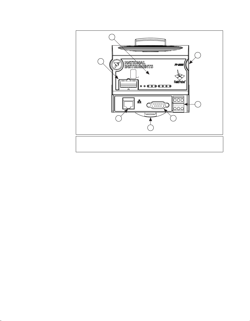
Chapter 1 Overview of the FP-20xx Network Module
1
2
3
Ethernet Controller Module
LabVIEW RT Series
SETTINGS
STARTUP
RESET
SAFE MODE
DISABLEVI
5
4
3
2
1
O
F
F
/
O
N
POWER
ABCD
STATUS
LINK
100 Mbps
ACTIVE
10/100 Mbps
RS-232
4
7
5
6
1 DIP Switches
2 LED Indicators
4 Power Connector
5 RS-232 Serial Port
6 Rail Clip
7 Ethernet Port
3 Local Bus Connector
Figure 1-1. FP-20xx Parts Locator Diagram
A FieldPoint bank consists of one network module, one or more terminal
bases, and one or more I/O modules. Each FP-20xx can support up to nine
I/O modules. Each bank can be accessed by an unlimited number of host
computers or FieldPoint modules, forming a distributed computing system.
The maximum number of FP-20xx network modules that can be installed
on your Ethernet network is limited only by your network topology.
The FP-20xx network module connects directly to a 10 or 100 Mbps
Ethernet network. The module auto-detects the speed of the connection
and configures itself accordingly.
Figure 1-2 shows an FP-20xx connected to an Ethernet network.
For detailed hardware specifications and cabling information, refer to
Appendix E, Specifications.
FP-2000/2010/2015 User Manual 1-2 ni.com
Page 10
Chapter 1 Overview of the FP-20xx Network Module
1
5
1FP-20xx Network Module
2 Terminal Base
3 I/O Module
Figure 1-2. FP-20xx Connected to an Ethernet Network
FieldPoint Software Overview
2
3
4
66 6
4 Ethernet Cable
5 Ethernet Hub/Switch
6 Ethernet Devices/Computers
Your FieldPoint software includes a configuration utility as well as server
and driver software for easy integration into application software packages.
These software components manage the low-level communications and
hardware details, simplifying programmatic access to I/O channels.
Version 3.0.1 of the FieldPoint software runs on
Windows 2000/NT 4.0/XP/Me/9x and includes the following components:
• FieldPoint Explorer configuration utility
• LabVIEW VIs
• LabWindows/CVI Functions
• Lookout driver
• Measurement Studio instrument drivers
• OPC Server
You can download a current version of FieldPoint software from the
National Instruments Web site. Using your Web browser, go to
© National Instruments Corporation 1-3 FP-2000/2010/2015 User Manual
ni.com
,
Page 11

Chapter 1 Overview of the FP-20xx Network Module
select Download Software»Drivers and Updates»Current Software
Versions»Fieldpoint Explorer, and follow the instructions on that page.
FP-20xx Setup Overview
The following list is an overview of the steps required to get up and running
with your FP-20xx and LabVIEW RT.
1. Install hardware as described in Chapter 2, Installing the Hardware
and Software.
a. Mount FP-20xx, terminal bases, and I/O modules.
b. Connect FieldPoint system to network.
c. Wire power to FieldPoint system.
d. Wire signals to I/O modules.
2. Install the software as described in Chapter 2, Installing the Hardware
and Software.
a. Install programming software (LabVIEW RT).
b. Install FieldPoint Explorer.
3. Configure the FieldPoint system, and verify the configuration,
as described in Chapter 3, Hardware and Software Configuration.
a. Configure FP-20xx network settings.
b. Configure I/O module ranges and settings.
c. Configure security.
d. Test channels.
e. Save settings.
4. Configure optional settings as described in Chapter 4, Feature Set
Description.
5. Develop your application, as described in Chapter 5, LabVIEW RT
Programming.
a. Launch LabVIEW RT.
b. Develop code.
c. Switch execution target to test code on FP-20xx.
d. Build application by building
FP-20xx.
e. Test embedded application.
6. Deploy system.
with LabVIEW RT targeted to
.exe
FP-2000/2010/2015 User Manual 1-4 ni.com
Page 12

Installing the Hardware
and Software
This chapter explains how to install the FieldPoint hardware and software.
What You Need to Get Started
To set up and use LabVIEW RT with the FP-20xx, you need the following:
❑
FP-20xx network module
❑
Mounting hardware (DIN rail or panel-mount accessory)
❑
Terminal base(s) and I/O module(s)
❑
Power supply
❑
Accessories: Ethernet cable, screwdriver
2
❑
FieldPoint Software CD
❑
A host PC running Windows 2000/NT 4.0/XP/Me/9x
❑
LabVIEW RT software
LabVIEW RT User Manual
❑
FieldPoint Safety Information
The following section contains important safety information that you must
follow when installing and using FieldPoint products.
Do not operate the FieldPoint product in a manner not specified in the user
manual or operating instructions. Misuse of the product can result in a
hazard. You can compromise the safety protection built into the product if
the product is damaged in any way. If the product is damaged, return it to
National Instruments for repair.
© National Instruments Corporation 2-1 FP-2000/2010/2015 User Manual
Page 13

Chapter 2 Installing the Hardware and Software
Do not substitute parts or modify the FieldPoint product. Use the product
only with the modules, accessories, and cables specified in the installation
instructions.
Always operate the FieldPoint product in a suitable enclosure that will
prevent unintentional access to live terminals and will prevent the spread
of fire.
Do not operate FieldPoint products in an explosive atmosphere or where
there may be flammable gases or fumes. If you need to operate FieldPoint
products in such an environment, the FieldPoint products must be in a
suitably rated enclosure. Operate the product only at or below Pollution
Degree 2. Pollution is foreign matter in a solid, liquid, or gaseous state that
can reduce dielectric strength or surface resistivity. The following is a
description of pollution degrees:
• Pollution Degree 1 means no pollution or only dry, nonconductive
pollution occurs. The pollution has no influence.
• Pollution Degree 2 means that only nonconductive pollution occurs in
most cases. Occasionally, however, a temporary conductivity caused
by condensation must be expected.
• Pollution Degree 3 means that conductive pollution occurs, or dry,
nonconductive pollution occurs which becomes conductive due to
condensation.
If you need to clean a FieldPoint product, use a soft nonmetallic brush.
The product mustbe completely dry and free from contaminants before you
return it to service.
Yo u must insulate signal connections for the maximum voltage for which
the FieldPoint product is rated. Do not exceed the maximum ratings for the
product. Do not install wiring while the product is live with electrical
signals. Do not remove or add terminal bases when power is connected to
the FieldPoint system. Avoid contact between your body and the terminal
base signal wiring when hot-swapping modules.
Operate FieldPoint products at or below Installation Category II.
The following is a description of installation categories:
• Installation Category I is for measurements performed on circuits not
1
directly connected to MAINS
1
MAINS is defined as the electricity supply system to which the equipment concerned is designed to be connected for either
powering the equipment or for measurement purposes.
FP-2000/2010/2015 User Manual 2-2 ni.com
. This category is a signal level such as
Page 14
Chapter 2 Installing the Hardware and Software
voltages on a printed wiring board (PWB) on the secondary of an
isolation transformer.
Examples of Installation Category I are measurements on circuits not
derived from MAINS and specially protected (internal)
MAINS-derived circuits.
• Installation Category II is for measurements performed on circuits
directly connected to the low-voltage installation. This category refers
to local-level distribution, such as that provided by a standard wall
outlet.
Examples of Installation Category II are measurements on household
appliances, portable tools, and similar equipment.
• Installation Category III is for measurements performed in the building
installation. This category is a distribution level, referring to
hard-wired equipment that does not rely on standard building
insulation.
Examples of Installation Category III include measurements on
distribution circuits and circuit-breakers. Other examples of
Installation Category IIIare wiring including cables, bus-bars, junction
boxes, switches, socket-outlets in the building/fixed installation, and
equipment for industrial use, such as stationary motors with a
permanent connection to the building/fixed installation.
• Installation Category IV is for measurements performed at the source
of the low-voltage (< 1,000 V) installation.
Examples of Installation Category IV are electric meters, and
measurements on primary overcurrent protection devices and
ripple-control units.
© National Instruments Corporation 2-3 FP-2000/2010/2015 User Manual
Page 15
Chapter 2 Installing the Hardware and Software
Mounting the FP-20xx and Terminal Bases
You can mount the FieldPoint system either to a DIN rail or directly on
a panel. Panel mounting is generally the more secure option, but DIN rail
mounting might be more convenient for your application. The following
sections give instructions for both mounting methods.
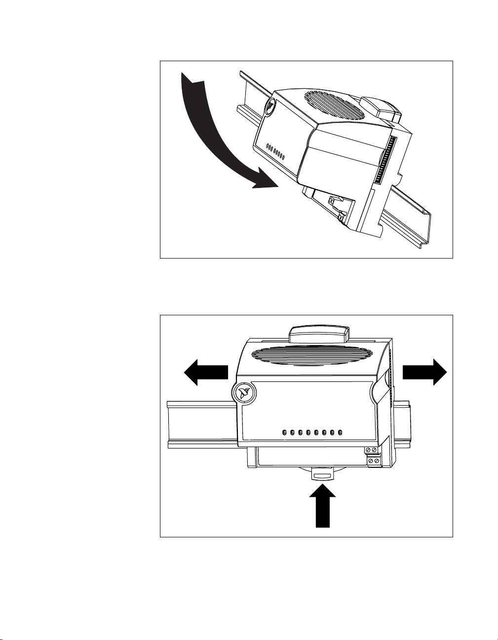
Mounting the FP-20xx on a DIN Rail
The FP-20xx network module has a simple rail clip for reliable mounting
onto a standard 35 mm DIN rail. Follow these steps if you choose to mount
the module on a DIN rail:
1. Write down the serial number from the back of the FP-20xx before you
mount it.
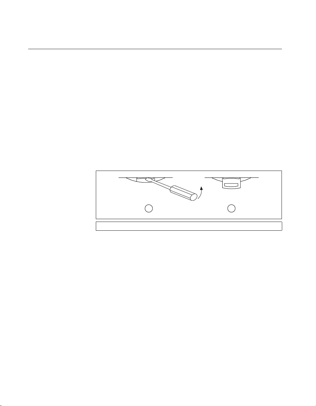
2. Use a flathead screwdriver to open the DIN rail clip to the unlocked
position, as shown in the following figure.
1 2
1 Rail Clip Locked 2 Rail Clip Unlocked
3. Hook the lip on the rear of the FP-20xx onto the top of a 35 mm
DIN rail and press it down onto the DIN rail, as shown in the following
figure.
FP-2000/2010/2015 User Manual 2-4 ni.com
Page 16
Chapter 2 Installing the Hardware and Software
4. Slide the FP-20xx to the desired position along the DIN rail. After it is
in position, lock it to the DIN rail by pushing the rail clip to the locked
position, as shown in the following figure.
After the FP-20xx is mounted to the DIN rail, connect the terminal base
to it.
© National Instruments Corporation 2-5 FP-2000/2010/2015 User Manual
Page 17
Chapter 2 Installing the Hardware and Software
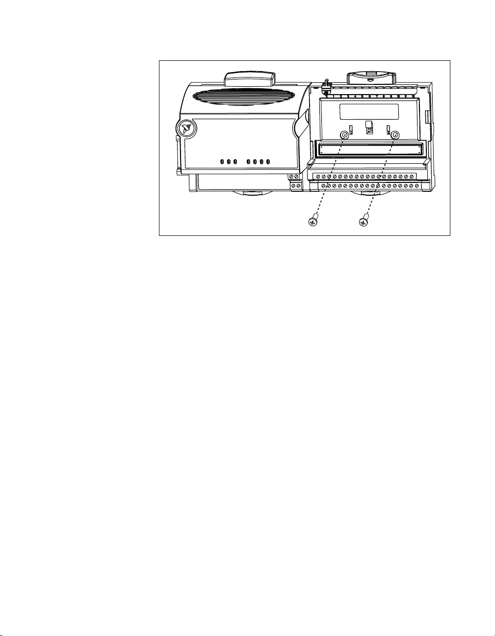
Connecting Terminal Bases with DIN Rail Mounting
Follow these steps to connect a terminal base to an FP-20xx network
module using DIN rail mounting.
Caution
is not applied to it while you install or remove terminal bases.
To avoid damaging the FP-20xx and the terminal bases, make sure that power
1. Mount the terminal base onto the DIN rail in the same way you
installed the network module.
2. Attach the terminal base to the FP-20xx by firmly mating the local
bus connectors. Be careful not to bend any pins.
3. To add more terminal bases, install them on the rail and connect their
local bus connectors together. In most cases a single FP-20xx
can support up to nine terminal bases, depending on the power
consumption of the I/O modules. Refer to the Wiring Power to the
FieldPoint System section for more information about power
requirements.
4. Place the protective cover onto the local bus connector of the last
terminal base on the bank, as shown in the following figure. Add
the rail locks by sliding them on and tightening the screws.
Removing the FP-20xx and Terminal Bases
from the DIN Rail
Remove an I/O module from its terminal base before lifting the terminal
base off the rail. To remove an FP-20xx network module or terminal base,
unlock it from the DIN rail by placing a screwdriver in the slot on the rail
clip and opening it to the unlocked position. After you disconnect the
network module from the local bus connector of the terminal base, you can
lift it off the rail.
FP-2000/2010/2015 User Manual 2-6 ni.com
Page 18
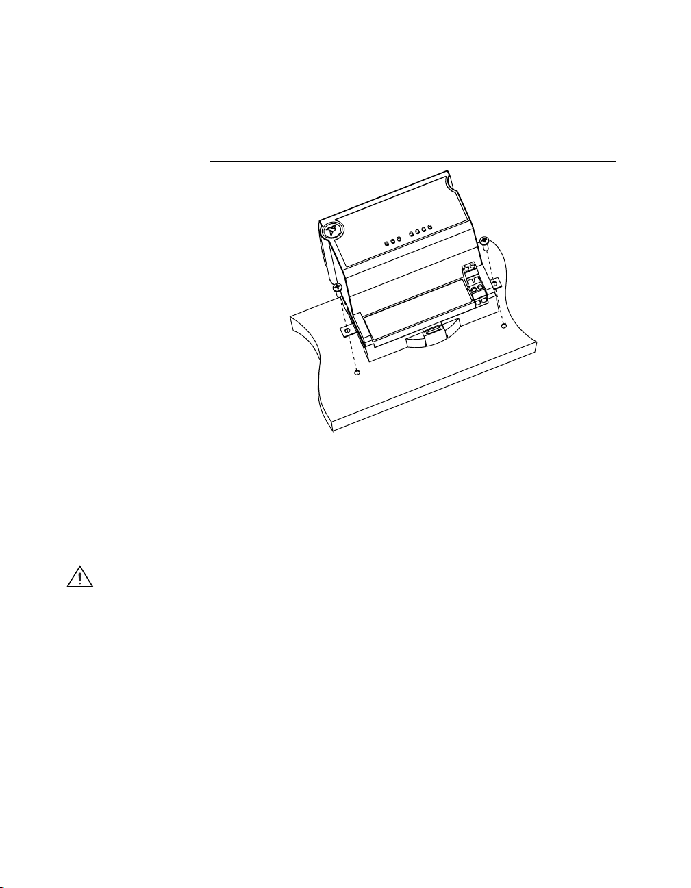
Mounting the FP-20xx toaPanel
Follow these steps if you choose to install the optional FieldPoint network
panel-mount accessory and mount the FP-20xx network module to a panel.
You can order the panel-mount accessory, part number 777609-01, from
National Instruments.
1. Write down the serial number from the back of the FP-20xx before you
mount it.
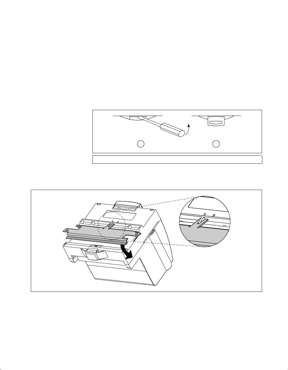
2. Use a flathead screwdriver to open the rail clip to the unlocked
position, as shown in the following figure.
1 Rail Clip Locked 2 Rail Clip Unlocked
3. Snap the panel-mount accessory onto the module, as shown in the
following figure.
Chapter 2 Installing the Hardware and Software
1 2
4. Lock the panel-mount accessory into place by pushing the rail clip to
the locked position.
© National Instruments Corporation 2-7 FP-2000/2010/2015 User Manual
Page 19
Chapter 2 Installing the Hardware and Software
5. Mount the FP-20xx to your panel with the panel-mount accessory,
as shown in the following figure. The installation guide that came with
the panel-mount accessory includes a template that you can use to drill
pilot holes for mounting.
Connecting Terminal Bases with Panel Mounting
You can install terminal bases directly, without using the panel-mount
accessory needed to mount the FP-20xx network module. Follow these
steps to connect terminal bases to the network module using panel
mounting.
Caution
is not applied to it while you install or remove terminal bases.
FP-2000/2010/2015 User Manual 2-8 ni.com
To avoid damaging the FP-20xx and the terminal bases, make sure that power
1. Drill pilot holes in the panel to mount the terminal bases. A drilling
template is provided with the network module panel-mount accessory.
2. Connect the terminal base to the FP-20xx by firmly mating the local
bus connectors. Be careful not to bend any connector pins.
3. Bolt, screw, or otherwise fasten the terminal base to the panel.
Make sure that the local bus connectors remain firmly mated after
the terminal base is mounted.
Page 20
Chapter 2 Installing the Hardware and Software
4. To add more terminal bases, repeat steps 1 through 3, mating the local
bus connectors of each new terminal base to the connector of the last
installed base. In most cases a single FP-20xx can support up to nine
terminal bases, depending on the power consumption of the I/O
modules. Refer to the Wiring Power to the FieldPoint System section
for more information about power requirements.
If all the pilot holes were correctly drilled, the local bus connectors
should remain firmly mated after all the bases are mounted to the
panel.
© National Instruments Corporation 2-9 FP-2000/2010/2015 User Manual
Page 21

Chapter 2 Installing the Hardware and Software
5. Place the protective cover onto the local bus connector of the last
terminal base on the bank, as shown in the following figure.
Removing the FP-20xx and Terminal Bases from
the Panel
To remove an FP-20xx network module and terminal bases from the panel,
first remove the terminal bases, starting with the last one, then remove the
network module.
Mounting I/O Modules onto Terminal Bases
Generally, it does not matter where you install each I/O module, except in
the following situations:
• If you plan to cascade power between any I/O modules using the V and
C terminals, those modules should be grouped together.
• For more accurate measurements, you might want to locate any
thermocouple modules away from heat sources, including network
modules or relay modules, unless you are mounting them on an
FP-TB-3.
FP-2000/2010/2015 User Manual 2-10 ni.com
Page 22
Chapter 2 Installing the Hardware and Software
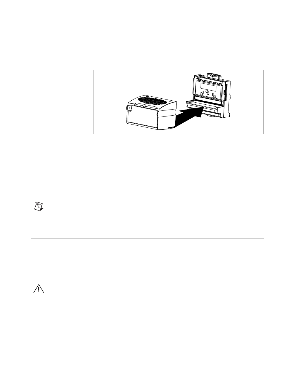
Refer to the following figure and follow these steps to connect an I/O
module to a terminal base:
1. Position the first module with its alignment slots aligned with the guide
rails on the terminal base.
2. Firmly press the module onto the terminal base. The terminal base
latch locks the I/O module into place when the ejector button pops up
on top of the terminal base.
3. Repeat this procedure to install additional I/O modules onto terminal
bases.
To remove a module, press the ejector button on top of the terminal base
and pull off the module.
Note
Some older modules may require more force to remove from the terminal base.
Make sure you firmly pull the module straight off the terminal base.
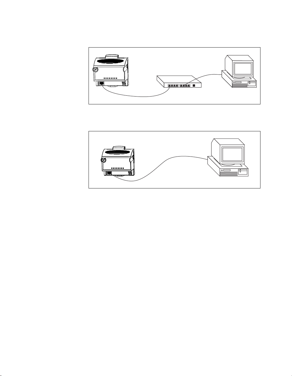
Connecting the FP-20xx to the Network
Connect the FP-20xx network module to an Ethernet network using the
RJ-45 Ethernet port on the module. Connect the RJ-45 Ethernet port of the
module to an Ethernet hub using a standard Category 5 Ethernet cable.
You also can connect the module directly to a computer using an Ethernet
crossover cable.
Caution
do not use a cable longer than 100 m. If you are using a 100 Mbps Ethernet, National
Instruments recommends using a Category 5 shielded twisted-pair Ethernet cable.
To prevent data loss and to maintain the integrity of your Ethernet installation,
© National Instruments Corporation 2-11 FP-2000/2010/2015 User Manual
Page 23
Chapter 2 Installing the Hardware and Software
The following figure shows the FP-20xx connected to an Ethernet hub.
The following figure shows the FP-20xx connected directly using a
crossover cable.
The host PC communicates to the FP-20xx over a standard Ethernet
connection. If the host PC is already configured on a network, you must
configure the FP-20xx on the same network. If neither is connected to a
network, you can connect the two directly using a CAT-5 crossover cable.
If you need to build your own cable, refer to Appendix E, Specifications,
for more information about Ethernet cable wiring connections.
In order to configure the FP-20xx, it must reside on the same subnet as the
host PC. If you want to use the FP-20xx on a subnet other than the one the
host PC is on, first connect and configure it on the same subnet as the host
PC, then reassign a static IP address for the subnet where you want it to be
and physically move it to the other subnet. Contact your network
administrator if you need assistance configuring the host PC and FP-20xx
on the same subnet.
FP-2000/2010/2015 User Manual 2-12 ni.com
Page 24
Chapter 2 Installing the Hardware and Software
Wiring Power to the FieldPoint System
Each FP-20xx on your network requires an 11–30 VDC power supply.
The FP-20xx filters and regulates the supplied power and provides power
for all the I/O modules in the bank. This power is sufficient for most
FieldPoint I/O modules. Refer to the documentation for the individual I/O
modules to determine whether they require any additional power in your
applications.
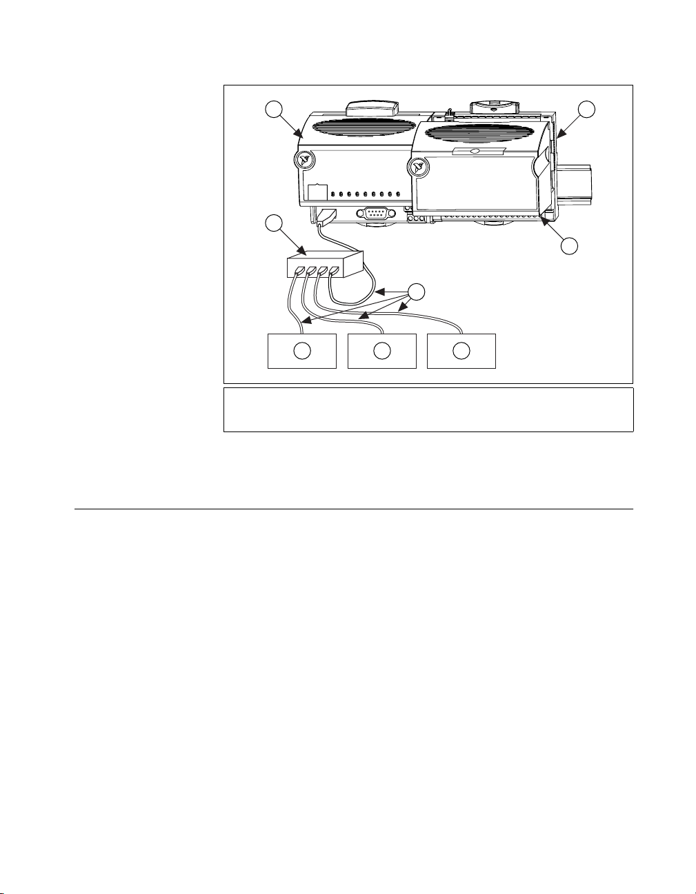
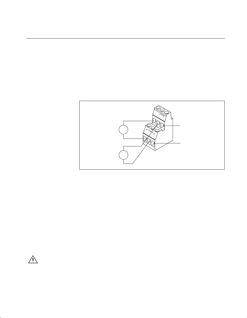
Figure 2-1 shows the 6-pin screw-terminal power connector on the
FP-20xx.
v
v
11-30 VDC
Backup Power
Supply
(optional)
11-30 VDC
Primary Power
Supply
+
–
+
–
c
c
c
v
V
To adjacent device
(optional connection)
C
Figure 2-1. FP-20xx Power Connector Pinout
Follow these steps to connect power to the FieldPoint system:
1. Connect the primary power supply to the center V and C pair. You
can connect an optional backup power supply to the left V and C pair.
The FP-20xx uses the power supply with the higher voltage level.
The V terminal for backup power is isolated from the other
V terminals. The right V and C pair provides a convenient means of
connecting power to the V and C terminals of a terminal base.
Figure 2-2 shows this optional connection, called cascading power.
To verify that your power supply is sufficient for your modules and
devices, refer to the Calculating Power for a FieldPoint Bank section
for instructions on calculating power requirements.
Caution
Cascading power defeats isolation between the cascaded modules.
2. Connect power to the FieldPoint modules that require external power
for inputs or outputs (may include output modules, counter modules,
PWM,PG,QUAD).RefertotheI/Omodule’s operating instructions
© National Instruments Corporation 2-13 FP-2000/2010/2015 User Manual
Page 25
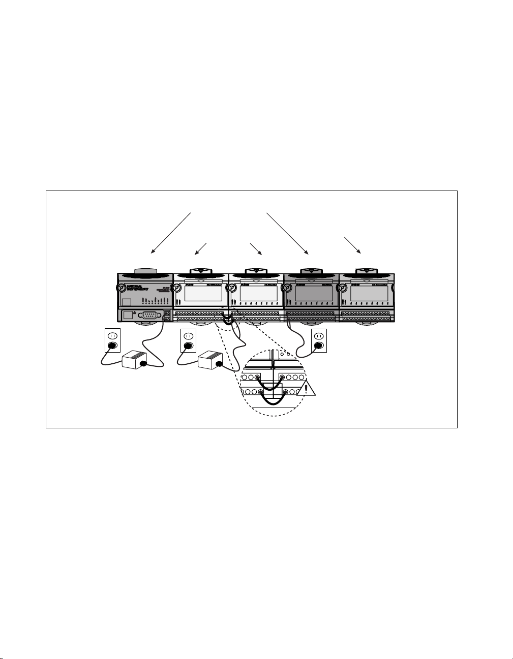
Chapter 2 Installing the Hardware and Software
for power requirement details. You can power a module by connecting
the V and C inputs on its terminal base to a separate power supply,
connecting the V and C outputs of a neighboring terminal base or
network module, or using a combination of both methods. If you want
to power field I/O devices from a terminal base, supply power to the
terminal base, and then connect the terminal base V and C output
terminals to the field device.
Figure 2-2 shows an example of a FieldPoint system correctly wired to
power sources.
Separate Power Supply
(Recommended)
Cascaded Power
(Reduces Isolation)
No External
Power Required
FP-TC-120FP-RLY-420FP-AO-200FP-AI-100FP-2000
Shades of gray indicate
different voltage potentials.
15
31 32 C
16 V
V
1
32
C
CAUTION: Cascading
17
18
power defeats isolation.
Figure 2-2. FieldPoint Bank with Power Connections
Calculating Power for a FieldPoint Bank
The power requirements for a FieldPoint bank that uses an FP-20xx
network module are calculated as follows:
Power =4.5W+1.1*∑(I/O Module Consumption)
This is the amount of power the FP-20xx network module consumes from
the power supply to power itself and the I/O modules. It does not include
any power consumed by devices that you wire to the terminal bases.
FP-2000/2010/2015 User Manual 2-14 ni.com
Page 26

The FP-20xx supplies 9 W of power to the I/O modules. Using certain I/O
modules that consume more than 1 W may reduce the total number of
I/O modules allowed in the bank to less than nine. Refer to the operating
instructions for each I/O module for power consumption information.
Connecting to Field Devices
Use each I/O module’s operating instructions, or the diagram under its
removable label, to help you connect your field devices.
Powering Up the FP-20xx
Plug in each power supply to the FieldPoint bank. At power-up, the
FP-20xx runs a power-on self test (POST) that takes several seconds.
You should see the POWER and STATUS LEDs come on. After about
five seconds, the STATUS LED begins flashing. This indicates that the
FP-20xx is ready to be configured, and you can proceed to installing the
FieldPoint software.
If you have already assigned an IP address to the FP-20xx,theSTATUS
LED turns off, and the A, B, C,andD LEDs come on for about 15 seconds
as LabVIEW RT starts up. Once they turn off, the I/O module READY
LEDs come on, and the FP-20xx is ready for use.
Chapter 2 Installing the Hardware and Software
If the STATUS LED does not light up as described here, refer to the
STATUS LED Error Indications sectionofAppendixC,Troubleshooting.
Installing Software on the Host PC
The FP-20xx has the embedded LabVIEW RT Engine and FieldPoint
software pre-installed, but you must install the necessary software on the
host PC. Follow these steps to install the FieldPoint software on the
host PC.
1. Install the software packages you plan to use, such as LabVIEW,
LabVIEW RT, Lookout, Measurement Studio, or LabWindows/CVI,
before you install the FieldPoint software. The FieldPoint software
installation installs the LabVIEW VIs and examples, Lookout driver
class, and LabWindows/CVI instrument driver only if it finds the
corresponding development software installed.
2. Close all other applications.
© National Instruments Corporation 2-15 FP-2000/2010/2015 User Manual
Page 27

Chapter 2 Installing the Hardware and Software
3. Insert the FieldPoint software CD into the CD-ROM drive on your
computer.
4. Follow the onscreen instructions to complete the installation.
Note
If the setup does not launch automatically, select Start»Run from Windows,
enter
d:\setup
,wheredis the letter of your CD-ROM drive, and select OK.
The hardware and software installation is now complete. Proceed to
Chapter 3, Hardware and Software Configuration.
FP-2000/2010/2015 User Manual 2-16 ni.com
Page 28
Hardware and Software
Configuration
This chapter describes the details of configuring FieldPoint hardware and
software, verifying the configuration, and accessing the channels on the
FP-20xx from other software running on the host PC.
Configuring the FP-20xx in FieldPoint Explorer
To get started with FieldPoint Explorer, follow these steps:
1. Make sure that LabVIEW RT and the FieldPoint hardware and
software have been installed as explained in Chapter 2, Installing the
Hardware and Software, and in the LabVIEW RT manual. Verify that
the FieldPoint system is powered on.
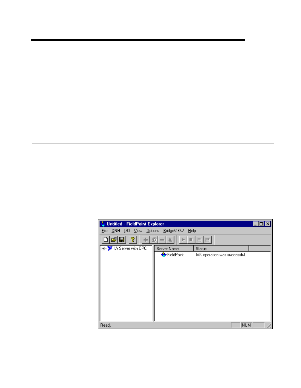
2. From the Windows Start menu, select Programs»National
Instruments FieldPoint»FieldPoint Explorer to launch FieldPoint
Explorer, shown in the following figure.
3
3. Click the + sign next to IA Server with OPC in the left pane to expand
the view. Then right-click FieldPoint and select Add a comm
© National Instruments Corporation 3-1 FP-2000/2010/2015 User Manual
Page 29
Chapter 3 Hardware and Software Configuration
resource to this server. The Comm Resource Configuration dialog
box appears.
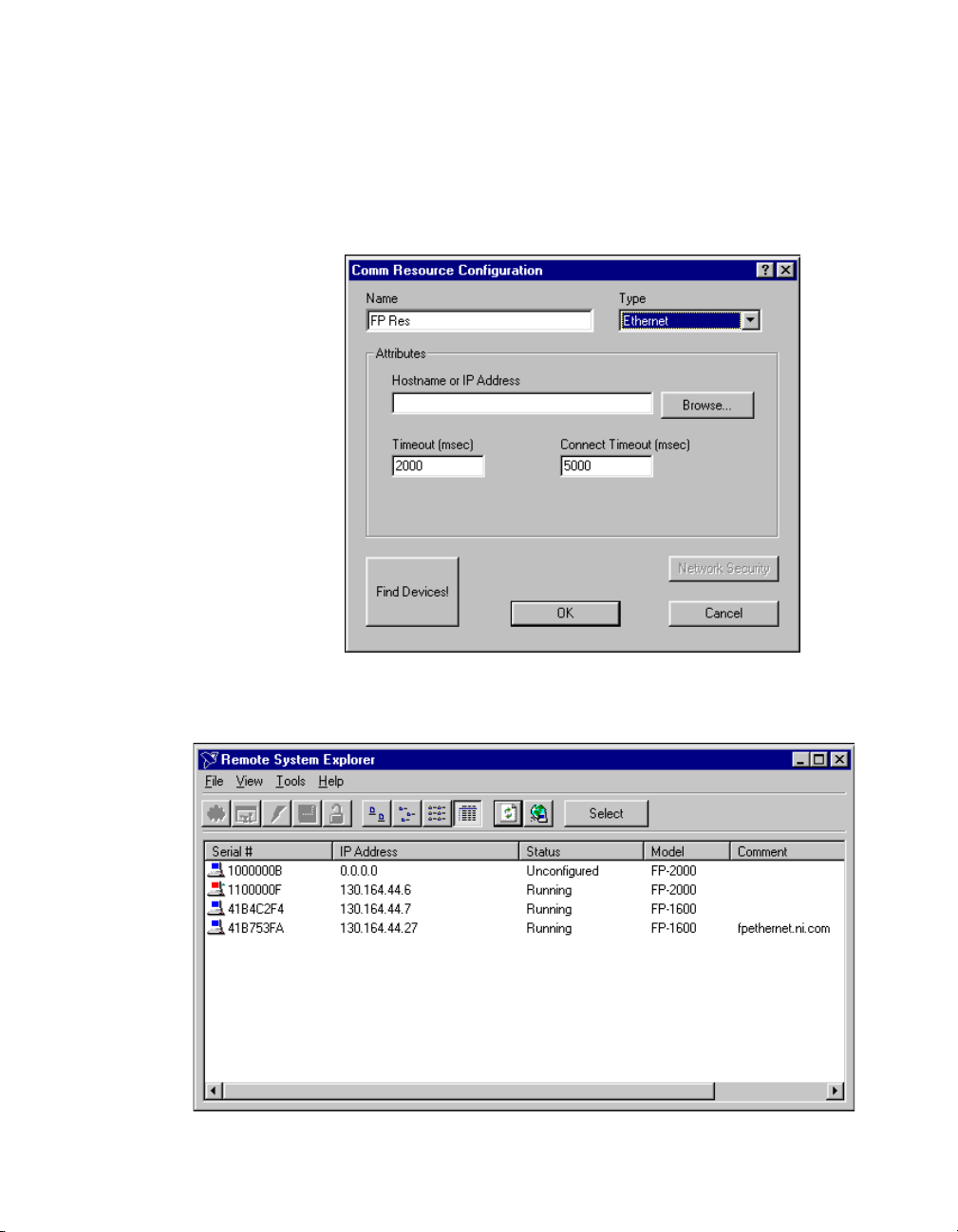
4. To use the FP-20xx,settheType to Ethernet, as shown in the
following figure. Each Ethernet comm resource represents a single
bank of FieldPoint modules on the network.
5. Click Browse to launch Remote System Explorer, shown in the
following figure.
FP-2000/2010/2015 User Manual 3-2 ni.com
Page 30

Chapter 3 Hardware and Software Configuration
Remote System Explorer searches for any FP-20xx or other National
Instruments Ethernet devices on the subnet. The serial number shown
corresponds to the serial number of your FP-20xx. The status of the
module is
Unconfigured
because you have not set an IP address
for it.
6. Double-click the serial number of the FP-20xx youwanttoconfigure.
Alternatively, you can right-click the network module and choose
Configure Device.
7. Enter values on the Network Settings tab of the System Configuration
dialog box, shown in the following figure. Refer to Appendix A,
Choosing Network Settings, for more information about choosing
appropriate addresses for these fields. You also can click Suggest
Values to let the software provide default parameters. If your network
does not have a gateway server or DNS server, you should set these
parameters to
0.0.0.0
.
• IP Address—The unique, computer-readable address of a device
on your network. An IP address is typically represented as four
numbers separated by periods (for example,
130.164.55.112
)
where the numbers can be between 0 and 255, inclusive.
• Subnet Mask—A code that helps the network device determine
whether another device is on the same subnet or a different subnet.
The most common subnet mask is
© National Instruments Corporation 3-3 FP-2000/2010/2015 User Manual
255.255.255.0
.
Page 31

Chapter 3 Hardware and Software Configuration
• Gateway—The IP address of a device that acts as a gateway
server, which is a connection between two networks.
• DNS Address—The IP address of a network device that stores
host names and translates them into IP addresses.
8. Enter values on the System tab of the System Configuration dialog
box, shown in the following figure.
• Host Name—This is the name that appears for the device
when you browse the network using Remote System Explorer.
Refer to the Giving Your FP-20xx a Host Name section of
Appendix A, Choosing Network Settings, for more information
about using this name on your network.
• Comment—To help you identify your FP-20xx.
• Password-protect Resets—Determines whether the user is
allowed to reset the FieldPoint bank remotely. If this checkbox is
selected, the user must provide the password in order to reset
the system remotely. Refer to the Locking/Unlocking Settings in
Remote System Explorer section for information about specifying
a password. You must disable resets from FieldPoint Explorer
separately by setting user access to Read Only or Deny Access.
Refer to the Setting Up Security for the FP-20xx section for more
information.
FP-2000/2010/2015 User Manual 3-4 ni.com
Page 32

Chapter 3 Hardware and Software Configuration
9. Enter an IP address for the Time Server on the Servers tab of the
System Configuration dialog box, shown in the following figure.
The Time Server is a networked computer that runs the National
Instruments Time Service. This is usually one of the computers that
you run FieldPoint software on. Time Server is not a required
parameter after the time has been set. The FP-20xx has an internal
battery-backed clock that provides consistent timestamps in the
absence of a Time Server.
10. Click OK in the System Configuration dialog box. Click Ye s when
prompted to reboot the FP-20xx.
After the FP-20xx has rebooted, it appears in Remote System Explorer
with the updated IP address and comment, as shown in the following
figure. If it does not appear, select View»Refresh or refer to the
FP-20xx Does Not Appear in Remote System Explorer Dialog Box
When Browsing section of Appendix C, Troubleshooting.
© National Instruments Corporation 3-5 FP-2000/2010/2015 User Manual
Page 33

Chapter 3 Hardware and Software Configuration
11. Highlight the module and click Select. When the new host name or
IP address appears in the Comm Resource Configuration dialog box of
FieldPoint Explorer, you can proceed to configuring your devices and
channels.
Finding and Configuring Devices and Channels
After you have configured the FP-20xx in FieldPoint Explorer, follow these
steps to configure your FieldPoint devices and channels.
1. In the Comm Resource Configuration dialog box, click Find Devices
to search for all of the FieldPoint devices on this communications
resource. If the Comm Resource Configuration dialog box is not
already open, right-click the Comm Resource in FieldPoint Explorer
and select Edit this comm resource.
If no devices are found, refer to the No Modules Found Error in
FieldPoint Explorer sectionofAppendixC,Troubleshooting.
FP-2000/2010/2015 User Manual 3-6 ni.com
Page 34

Chapter 3 Hardware and Software Configuration
2. After the FieldPoint modules are found, click the + sign next toFP Res
in the left pane to expand the device hierarchy and display the modules
found on the network, as shown in the following figure.
The hierarchy includes all of the modules connected to the FP-20xx.
The default name of each device found includes the name of the
FieldPoint module, followed by a space, the @ sign, and the address of
the module (for example,
FP-2000 @0
). For each module found,
one I/O Item is created for each channel on the module, and if all the
channels are of the same type, one I/O Item is created to represent all
the channels on that module collectively.
© National Instruments Corporation 3-7 FP-2000/2010/2015 User Manual
Page 35

Chapter 3 Hardware and Software Configuration
3. To configure the hardware settings of a particular I/O module,
right-click the device name and select Edit this device.TheDevice
Configuration dialog box appears, as shown in the following figure.
For output modules, you can choose settings for Watchdog
Configuration. Refer to the Guarding against Network Failures
(Network Watchdog) section of Chapter 4, Feature Set Description,
for more information about the network watchdog feature.
FP-2000/2010/2015 User Manual 3-8 ni.com
Page 36

Chapter 3 Hardware and Software Configuration
4. Click Channel Configuration to access the Channel Configuration
dialog box. In the following figure, an FP-TC-120 thermocouple
module is selected.
Note
Configuration options are module dependent. The options listed here might not be
available for your particular module.
Make your selections in this dialog box as follows:
a. Select the type of channel to show, then select the channel(s) that
you want to change. To select more than one channel, clear the
One channel at a time checkbox.
b. Set the range and output values of the selected channel(s).
c. Set the deadband for data communication over the network.
The deadband setting is a percentage of the full-scale range.
Note
A deadband for analog or count channels is applied to the data in determining
whether the data is transmitted to devices on the network. The deadband is not applied to
embedded FieldPoint VIs accessing channels on I/O modules attached to the FP-20xx.
However, using DataSocket to access channels on the attached I/O modules is considered
a network transmission, and the deadband is applied.
© National Instruments Corporation 3-9 FP-2000/2010/2015 User Manual
Page 37

Chapter 3 Hardware and Software Configuration
d. Set attributes for selected channel(s) by selecting the attribute and
entering the desired value.
e. Send commands to the selected channel(s) by choosing a
command and value and clicking Send.
f. Repeat this procedure for each channel you want to configure.
g. Click OK,orclickApply to save the changes and continue to
configure channels. When you click OK or Apply, the changes
are immediately sent to the device and saved in its nonvolatile
memory.
Saving Hardware Configuration as Power-Up State
When you are satisfied with the hardware configuration of your FieldPoint
system, you can save this configuration as the new power-up state for the
bank.
1. Right-click the FP-20xx network module in the left pane of FieldPoint
Explorer, and select Edit this device.
2. Clear the factory configuration checkbox.
3. Specify the power-up settings with either of the following options:
• If you want only the range and attribute settings you configured in
the Finding and Configuring Devices and Channels sectiontobe
savedaspower-upstates,clickOK. These settings are written to
the nonvolatile memory of the network module.
• If you want to save power-up values for the range and attribute
settings and also all the current output states of the output
channels, click Snapshot. This stores the current ranges,
attributes, and output values of the bank to the nonvolatile
memory of the network module. Click OK when you are finished.
Caution
specified for individual channels in the Channel Configuration dialog box.
FP-2000/2010/2015 User Manual 3-10 ni.com
Using the Snapshot feature overwrites any power-up values you may have
Refer to the Storing a Custom Power-Up Configuration section of
Chapter 4, Feature Set Description, for more information about
configuring and changing the power-up values. Refer to the Guarding
against Network Failures (Network Watchdog) section of Chapter 4,
Feature Set Description, for information about configuring a network
watchdog to guard against network failures.
Page 38

Using Other Features and Options
in Remote System Explorer
You can access Remote System Explorer by right-clicking the Comm
Resource in FieldPoint Explorer, selecting Edit this comm resource,
then clicking Browse. You can use the Remote System Explorer toolbar
buttons, Tools menu, or right-click menu to access the following features:
• Configure Device—Use to configure the IP address, comment,
and other parameters for the selected FP-20xx.
• Install/Upgrade Software—Use to install or upgrade LabVIEW RT
software on the selected FP-20xx.
• Reboot Device—Use to reboot the selected FP-20xx.
• View Installed Software—Use to view the LabVIEW RT and driver
software versions installed on the selected FP-20xx.
• Lock/Unlock Device—Use to lock or unlock the system configuration
with a password.
• Device Location—Use to change the search location for FP-20xx
modules to the local subnet or to a specified IP address.
• View Error Log—Use to obtain detailed error information if you need
to contact National Instruments technical support.
Chapter 3 Hardware and Software Configuration
You can use the Remote System Explorer toolbar buttons or View menu to
access the following features:
• Large icon view—Changes the view in the main window to large
icons.
• Small icon view—Changes the view in the main window to small
icons.
• List view—Changes the view in the main window to a list.
• Detailed view—Changes the view in the main window to a list with
additional information such as serial number, IP address, status,
model, and comment.
• Refresh Browse List—Refreshes the list of FP-20xx modules and
other National Instruments Ethernet devices found on the local subnet
or at the specified IP address. Changes to IP address, comment, and so
on do not appear in Remote System Explorer until you reboot the
selected system and click Refresh Browse List.
© National Instruments Corporation 3-11 FP-2000/2010/2015 User Manual
Page 39

Chapter 3 Hardware and Software Configuration
Setting Up Security for the FP-20xx
You can set network security options to limit host access, and you can lock
the settings made in Remote System Explorer.
Configuring Network Security
You can limit host access to the FP-20xx by setting access permissions for
different host machines. The default setting allows Read/Write access to all
host machines. To change the network security settings, follow these steps.
1. Right-click the comm resource in FieldPoint Explorer and select Edit
this comm resource. The Comm Resource Configuration dialog box
appears with the Network Security button enabled.
2. Click Network Security. The Network Security Settings dialog box
appears with the current settings, as shown in the following figure.
If your host machine does not have access to the FP-20xx,theAccess
List is empty and dimmed.
3. Make your additions or changes in the dialog box, as follows:
• If you have an IP Access List savedinafileoryouwantyour
FP-20xx security settings to match another FP-20xx unit, you can
import those setting by selecting the Import checkbox. Then
select the source (from file or from device). The settings read
from the source are shown in the Access List for you to modify,
if needed.
FP-2000/2010/2015 User Manual 3-12 ni.com
Page 40

Chapter 3 Hardware and Software Configuration
• To add a host machine to the list, enter its IP address in the
IP Pattern edit box, select the desired access type (Read/Write,
Read Only,orDeny Access)fromtheAccess Typelist, then click
Add. You can use the * wildcard when specifying the IP address.
For example, to give Read/Write access to all hosts, enter
IP Pattern edit box, or to deny access to all machines on the
111.222.333 subnet, enter
111.222.333.*
in the IP Pattern
edit box.
• To remove a host machine from the list, either click the entry or
type the entry in the IP Pattern edit box, then click Remove or
press the <Del> key.
Note
Once you modify the list, any IP Address that does not have any matching entry is
denied access to the FP-20xx.
• To change the order of the entries in the list, select an entry and
click the up arrow or down arrow button that is located next to the
Access List. A new entry is always added to the end of the list.
You can have multiple matching entries for a given IP address.
In that case, the first entry that matches the IP address is used,
starting from the bottom of the list.
• To s ave t he IP Access List to a file to be used for other FP-20xx
modules, select the Save checkbox and enter a file name.
4. Once you are satisfied with the changes, click OK. A dialog box
appears, prompting you for the password. After you enter the password
and click OK, your changes are applied to the FP-20xx.
*
in the
Locking/Unlocking Settings in Remote System Explorer
After you configure the FP-20xx, you can lock the settings made in Remote
System Explorer with a password to prevent others on your network from
changing the configuration. In addition, a host PC on the network cannot
target LabVIEW RT to the FP-20xx without a password unless the host is
in the RT Target: Access list.
Complete the following steps to lock or unlock the settings made in Remote
System Explorer:
1. Right-click the Comm Resource in FieldPoint Explorer, choose Edit
this comm resource, and click Browse to launch Remote System
Explorer.
2. Click the network module, then select Tools»Lock/Unlock Device.
A checkmark by this menu item indicates that the device is locked.
© National Instruments Corporation 3-13 FP-2000/2010/2015 User Manual
Page 41

Chapter 3 Hardware and Software Configuration
3. In the Locking System Configuration dialog box, enter a password to
lock or unlock the device.
4. Click OK.
If you need to unlock the device configuration and you do not know the
password, you must reset the FP-20xx and reconfigure it. Refer to
Appendix B, Resetting the FP-20xx, for more information about resetting
the FP-20xx.
Downloading Item Information to the FP-20xx
Every time you select File»Save in FieldPoint Explorer, the FieldPoint
file. This file is used to access the
system configuration is saved in a
configuration information, such as channel name, from other host
applications like LabVIEW or LabWindows/CVI. To provide the same
functionality for LabVIEW RT applications running on an FP-20xx,the
item names pertaining to the network module bank are also downloaded to
the network module whenever you select File»Save, assuming the network
module is powered on and connected to the network.
Note
To download the item names without saving the
Resource and select Download Configuration. To disable a configuration download
when you select File»Save, uncheck Options»Download Configuration On Save.
.iak
file, right-click the Comm
.iak
Verifying the Configuration
You can verify the installation and configuration by monitoring an I/O
channel or writing to an output channel from FieldPoint Explorer.
Monitoring an I/O Channel
You can monitor FieldPoint devices that you have configured. In the left
pane of FieldPoint Explorer, select one of the devices, then click the green
arrow icon in the toolbar to start monitoring the items of that device.
The tag symbols of the items in the list view pane turn blue to show that
they are being monitored. As shown in Figure 3-1, the Value column shows
the current value of the I/O channels defined by the I/O Items, and the
Status column shows any error conditions received while communicating
with the FieldPoint network. Timestamp is the time when the FP-20xx
made the value available to the host PC.
Click the red square icon in the toolbar to stop monitoring the items.
FP-2000/2010/2015 User Manual 3-14 ni.com
Page 42

Figure 3-1. Using FieldPoint Explorer to Monitor I/O Channels
Writing to an Output Channel
You can write to output channels of I/O Items that you have configured.
1. In the left pane of FieldPoint Explorer, select a device with output
channels.
2. Select the I/O Item in the right pane that corresponds to the channel
to which you want to write.
3. Click the pencil and paper icon in the toolbar to write to the I/O
channel(s) represented by the I/O Item.
Chapter 3 Hardware and Software Configuration
© National Instruments Corporation 3-15 FP-2000/2010/2015 User Manual
Page 43

Chapter 3 Hardware and Software Configuration
4. Enter the value you want to write in the Value field and click Write to
write the value out. The value must be in the range of the channel that
you configured in the Finding and Configuring Devices and Channels
section. For example, if the channel was configured for a range of
0.0035 A to 0.021 A, and you want to write a value of 0.010 A
(10 mA), enter
with a Boolean range, enter
Note
If your PC is configured to use a comma as a decimal symbol, enter
0.010
in the Value field. For discrete I/O channels
in the Value field.
1or0
Using the FP-20xx from Host Applications
The primary intended use for the FP-20xx is to run LabVIEW RT, but you
can use the module with other software on your host PC, even while you
are using it to run LabVIEW RT. The following sections explain how to
access the channels on the FP-20xx from software running on the host PC.
Lookout and the FP-20xx
The FP-20xx network module integrates easily with National Instruments
Lookout 4.0 and later. You can access the module the same way you would
access another desktop computer running Lookout. You can access the
channel data, ranges, attributes, and commands from Lookout, as well as
several control variables, such as Reset and Snapshot.
0,010
.
To access the FP-20xx with Lookout 3.8 or earlier, use the FieldPoint OPC
server. You cannot use the FieldPoint 3.8 Lookout driver class with the
FP-20xx.
To use the FP-20xx with Lookout 4.0 or later, follow these steps:
1. Configure the FP-20xx in FieldPoint Explorer as describe
Configuring the FP-20xx in FieldPoint Explorer section.
2. Start Lookout, and create a new process or open an existing one.
3. Register the FP-20xx as a networked computer in Lookout. Select
Object»Object Explorer or Object»Connection Browser from the
menu bar and right-click Network. Choose Register network
computer from the pop-up menu. Type the IP Address or host name of
the FP-20xx in the Computer name field and click OK.
4. When you create a Lookout object or expression, you can connect it to
data on the FP-20xx network module. In the Insert Expression dialog
box, click Network to browse the registered computers and FP-20xx
FP-2000/2010/2015 User Manual 3-16 ni.com
d in the
Page 44

modules. Click the IP address or host name of the network module and
browse to the desired data.
An alternative method is to use the
data.
LabVIEW VIs and the FP-20xx
When you install the FieldPoint software, a library of FieldPoint VIs is
created if LabVIEW has already been installed on your computer. The
FieldPoint VIs (FP Open, FP Get Configuration Info, FP Create Tag,
FP Advise, FP Read, FP Write, and FP Close) directly access the I/O Items
you configured in the FieldPoint Explorer program. For help using these
VIs, refer to the examples in
the FieldPoint LabVIEW Help, which is in the same program group as
FieldPoint Explorer on the Windows taskbar. You can use this same set
of VIs to access the FP-20xx from the host PC or to run an embedded
application. For more information about programming embedded
applications for the FP-20xx, refer to Chapter 5, LabVIEW RT
Programming.
A simple FieldPoint application to read an I/O Item might only need to use
four of the VIs. To create an example of such an application, complete the
following steps.
Chapter 3 Hardware and Software Configuration
fpoint.cbx
LabVIEW\examples\FieldPoint
to access the channel
or use
1. Use FP Open to open the server. By default, the server opens with the
configuration file you last saved with FieldPoint Explorer.
2. Use FP Create Tag to create a handle to an I/O Item that you defined
in FieldPoint Explorer. You provide three string names to this VI to
indicate which I/O Item you want access to. These three strings are
the names given to the communications resource, the device, and the
I/O Item.
Note
The strings provided to the VI must exactly match the names in FieldPoint Explorer,
including spaces and letter case.
3. Use FP Read.vi to monitor an I/O Item. You should also add a delay
into the loop so that the loop operates at your desired rate. Otherwise,
it may load the processor at 100% and lock the software in the module.
To write to an Output Item, use FP Write instead of FP Read.
Note
You may use FP Advise in place of FP Read. However, it is best not to place anything
else in a while loop with FP Advise. When using FP Advise, you can configure its timing
as an input to the VI. Also, do not put more than one FP Advise VI in a loop. All VIs in a
© National Instruments Corporation 3-17 FP-2000/2010/2015 User Manual
Page 45

Chapter 3 Hardware and Software Configuration
loop execute only once each time a loop runs, and FP Advise VIs only complete at their
advise rate. If you had more than one FP Advise VI in the loop, the loop (and therefore all
of the FP Advise VIs in the loop) would only execute at the slowest rate of the Advises.
The loop might not execute more than once if any of the Advises is set to complete
“On Data Change” and the data of the corresponding I/O Item never changes.
4. Use FP Close to close the server. This action also stops all pending
advise operations. Be sure to use only one FP Close.
5. The following figure gives an example of a LabVIEW diagram with
FieldPoint items.
LabWindows/CVI Functions and the FP-20xx
When you install the FieldPoint software, a LabWindows/CVI instrument
driver for FieldPoint is installed if LabWindows/CVI has already been
installed on your computer. This instrument driver includes function panels
to call C functions that directly access the I/O Items you configured in the
FieldPoint Explorer program. In addition, a set of sample projects is placed
in your
LabWindows/CVI Samples
the best way to get familiar with these functions. The FieldPoint CVI Help
document is in the same program group on the Windows taskbar as
FieldPoint Explorer. This help document describes each function in the
instrument driver with a description of the C syntax, a description of each
parameter, and a list of possible error codes.
FP-2000/2010/2015 User Manual 3-18 ni.com
directory. Using these examples is
Page 46

Note
FieldPoint CVI Interface Compatibility Modes—The FieldPoint software ships
) files to support the different compiler compatibility modes that
with object (
.obj
LabWindows/CVI supports (Microsoft Visual C/C++, Borland, Watcom, and Symantec).
When the FieldPoint software is installed, the
compatibility mode is installed.
FieldPoint OPC Server and the FP-20xx
The FieldPoint OPC server conforms to the OPC Data Access 2.0 standard.
OPC (OLE for Process Control) is an industry-standard device interface
specification that provides interoperability between field devices such as
FieldPoint and application software packages. The FieldPoint OPC server,
like the other FieldPoint interfaces, imports the I/O Items that you
configured in FieldPoint Explorer and makes them available as OPC Items
to any OPC client. Therefore, if two computers are networked together, it
is possible for an OPC client on one computer to access FieldPoint
hardware connected to the OPC server on another computer.
OPC clients differ in the features they offer and their presentation of the
OPC interface. However, the basic steps involved are similar for most OPC
clients.
Chapter 3 Hardware and Software Configuration
file corresponding to the configured
.obj
Follow these steps to use the FieldPoint OPC server:
1. Launch your OPC client.
2. Open the FieldPoint OPC server,
Instruments.OPCFieldPoint
National
, from the OPC client.
This server was registered with Windows when you installed the
FieldPoint software. OPC clients should be able to show you a list
of available registered servers, but you might have to type this name
in yourself. The OPC client might automatically connect to the server
when you select it, but if you are given the option to explicitly connect
to the FieldPoint OPC server, you should do so.
3. Create a group.
Groups are a collection of I/O Items. Some OPC clients might not give
you the option of creating groups, or they might be created for you.
4. Select the I/O Items, which you configured in FieldPoint Explorer, that
you want to read or write as a part of this group.
Many OPC clients can use the Browse Address Space feature of
the FieldPoint OPC server to show you a list of all of the I/O Items
you configured in FieldPoint Explorer. However, if the OPC client you
are using does not support this feature, you might need to type the Item
IDs of the I/O Items directly. The naming convention of the FieldPoint
© National Instruments Corporation 3-19 FP-2000/2010/2015 User Manual
Page 47

Chapter 3 Hardware and Software Configuration
Item IDs is
where the Comm resource name, Device name, and I/O Item name are
the names given in FieldPoint Explorer. For example, an Item ID
associated with one of the I/O Items might be the following:
FP Res\FP-TC-120 @1\Channel 0
In most cases, the preceding steps are all that is required to configure an
OPC client to read from I/O Items of the FieldPoint OPC server. In some
cases, the OPC client might require more information about the FieldPoint
OPC server. The following list contains additional information about the
FieldPoint OPC server, which you may find helpful.
• The FieldPoint OPC server does not require an access path. Some OPC
clients expect the access path to be included in the Item ID name or
might request the access path when you select I/O Items. You should
be able to leave the access path blank (empty string).
• The FieldPoint OPC interface is an out of process server.
• The FieldPoint OPC server supports both synchronous and
asynchronous reads and writes.
• The FieldPoint OPC server uses the GetErrorString method to return
error and diagnostic messages from the FieldPoint server and
hardware. OPC clients that do not support this method might give you
error messages like “Bad, non-specific” along with an error code.
Some OPC clients that do not support this GetErrorString method still
provide a way for you to manually look up the FieldPoint message
corresponding to the error code using this method.
Comm resource name\Device Name\I/O Item name
Data Communications
The FP-20xx network module provides several methods for
communicating and sharing data with other FieldPoint systems, computers,
and devices. The most common methods are to use DataSocket, serial VIs,
TCP VIs, UDP VIs, or Data Publishing VIs, as described in the following
sections.
DataSocket
DataSocket, a programming technology based on industry-standard
TCP/IP, simplifies live data exchange between different applications on
one computer or between computers connected via a network. DataSocket
was designed as an easy-to-use, high-performance programming interface
for sharing and publishing live data in measurement and automation
applications. You can use DataSocket VIs to obtain data from other
FP-2000/2010/2015 User Manual 3-20 ni.com
Page 48

Chapter 3 Hardware and Software Configuration
DataSocket servers, Lookout or LabVIEW DSC module applications,
and data published by the Data Publishing VIs.
DataSocket uses uniform resource locators (URLs) to specify absolute
paths to data items. A URL consists of three separate components:
protocol, network address,and locator. You are probably most familiar with
URLs from using a Web browser. For example,
support/fieldpoint
www.ni.com
is the network address, and
is a URL in which
http://www.ni.com/
is the protocol,
http
support/fieldpoint
is
the locator.
The FieldPoint software package installs a DataSocket URL browser in
LabVIEW. To launch the browser, select Tools»Browse Network for
DataSocket URLs. Enter the IP address of the FieldPoint device or
computer you want to browse, and click Refresh. After a short pause,
the available DataSocket servers appear in the window. Open each server to
access an item on that server, as shown in the following figure. Once an
item has been highlighted, its URL is displayed in the URL field. You can
use copy <Ctrl-C> and paste <Ctrl-V> to insert the URLs into the
DataSocket read and write VIs.
© National Instruments Corporation 3-21 FP-2000/2010/2015 User Manual
Page 49

Chapter 3 Hardware and Software Configuration
DataSocket URLs for FieldPoint I/O Modules
The following is an example of a DataSocket URL that points to a specific
channel of a FieldPoint I/O Module:
lookout:\\130.164.44.8\FP\1AI\01
In this URL,
lookout
the FieldPoint Ethernet network module, and
is the protocol,
130.164.44.8
FP\1AI\01
is the IP address of
is the locator.
The FieldPoint Process part of a URL provides the parent folder from
which you access all data items in a FieldPoint bank. The FieldPoint
Process part of a URL has the following format:
\\[machine]\FP
where
[machine]
is the IP address or hostname of the FieldPoint Ethernet
network module.
The I/O Module Folder part of a URL provides the sub-folder from which
you access all data items from a specific FieldPoint I/O module. The I/O
Module Folder part of a URL has the following format:
\\[machine]\FP\[n]
where
consists of the numeric address and name of the I/O module. The
[n]
address of the I/O module is an integer from 1 to 9, where 1 represents the
I/O module closest to the network module and 9 represents the I/O module
farthest from the network module. The folder
\\130.164.44.8\FP\1AI
indicates the I/O module closest to the network module, and the AI means
that it is an analog input module.
The Channel Data part of a URL provides the scaled data value of the input
or output value for a specific channel. The Channel Data part of a URL has
the following format:
\\[machine]\FP\[n]\[channel]
where
[channel]
is a two-digit decimal number between 00 and 15.
The following figure shows a DataSocket URL with Channel Data.
FP-2000/2010/2015 User Manual 3-22 ni.com
Page 50

Chapter 3 Hardware and Software Configuration
The locator is read as channel 0 (00) of the analog input module in position
one (the first position to the right of the network module) on the bank.
Note
If you are making only one connection to the FP-20xx, the Lookout protocol
performs better than OPC or DSTP (DataSocket Transfer Protocol).
Publish Data VI
You can use the Publish Data VI on the FieldPoint palette to create items
and groups that are published using the National Instruments Ethernet
(Lookout) protocol. A host computer or FP-20xx can link to these items
using DataSocket or using the native connection capabilities of Lookout
or the LabVIEW DSC module. The Publish Data VI creates data that other
VIs and applications can browse and read, write, or read/write from the
FP-20xx. These items will also be accessible in FieldPoint Explorer and the
FieldPoint OPC server.
Serial VIs
You can use the LabVIEW Serial VIs to communicate with other serial
devices through the RS-232 port on the FP-20xx. For example, you can use
the supplied FieldPoint Optomux library to communicate with an FP-1000
connected to the FP-20xx. Refer to the FP-1000/1001 Programmer
Reference Manual for more information about the Optomux VIs.
Note
The FP-20xx does not support VISA.
TCP and UDP VIs
You can use the LabVIEW TCP VIs to publish data from the FP-20xx to
computers or devices on the network using TCP-based protocols. You can
use the LabVIEW UDP VIs to publish data from the FP-20xx to computers
on the network using UDP (User Datagram Protocol).
Note
The TCP and UDP VIs provide low-level access to your network. Use them only
when the supplied protocols do not fit into your application.
© National Instruments Corporation 3-23 FP-2000/2010/2015 User Manual
Page 51

4
Feature Set Description
This chapter describes the feature set for the FP-20xx network module.
Guarding against Network Failures (Network Watchdog)
The network watchdog feature of the FP-20xx enables you to guard your
system against failures in the network connection, cables, or host computer.
If the network watchdog is enabled and the FP-20xx loses communication
with all hosts or clients over the network, the FP-20xx sets its output
channels to predefined values (the watchdog state).
Note
National Instruments recommends leaving the network watchdog disabled when
you are running embedded applications on the FP-20xx.
Network watchdog output values can be different than power-up output
values. For example, you may want to turn on an output value when you
power up, but turn it off if network communication is lost.
The network watchdog for the bank is disabled by default. Follow these
steps to enable it:
1. In FieldPoint Explorer, right-click an output module and select
Edit this device.
2. Select Enable or Enable on Use for the current watchdog
configuration.
3. Click Channel Configuration, then configure these settings:
• Enable/disable the watchdog for each channel.
• Enter a watchdog data value for each channel.
4. Click OK.
© National Instruments Corporation 4-1 FP-2000/2010/2015 User Manual
Page 52

Chapter 4 Feature Set Description
5. In the left pane of FieldPoint Explorer, right-click the FP-20xx, select
Edit this device, and configure these settings:
• Clear the factory configuration checkbox.
• Enable network watchdog for the bank.
• Enter a network watchdog timer value for the bank, a value that
specifies the maximum allowable period of lost communication
with hosts or clients over the network.
6. Click OK.
7. Select File»Save.
In addition to the network watchdog, the FP-20xx network modules support
a hardware watchdog that you can set up in LabVIEW RT. The VIs to
control the hardware watchdog are on the FieldPoint palette. Refer to the
Hardware Watchdog section of Chapter 5, LabVIEW RT Programming,
or to the examples in
information about the hardware watchdog.
labview\examples\rt\RT watchdog
Storing a Custom Power-Up Configuration
,formore
Setting a Power-Up State with the Snapshot Method
The Snapshot feature provides a single-step method for storing the current
state of your FieldPoint hardware for use as the power-up state of the bank.
Caution
for individual channels in the Channel Configuration dialog box.
FP-2000/2010/2015 User Manual 4-2 ni.com
Using the Snapshot feature overwrites any power-up values you have specified
1. Set the hardware to the state you want to use as a power-up state,
including output values, ranges, and attributes.
2. Right-click the FP-20xx in the left pane of FieldPoint Explorer, and
select Edit this device.
3. Clear the factory configuration checkbox.
4. Click Snapshot.ClickYes and OK to approve the change.
5. Click OK in the Device Configuration dialog box.
6. Select File»Save.
To make incremental changes to the power-up values of individual
channels, use the procedure described in the Configurable Power-Up
Method section.
Page 53

Configurable Power-Up Method
With the configurable power-up state feature, you can define the power-up
configuration on a module-by-module basis. You do not need to set any of
the channels to the desired power-up state, as you would with the Snapshot
feature. But you could use the configurable power-up method to adjust
previously stored Snapshot information.
1. In FieldPoint Explorer, right-click an I/O module and select Edit this
device.
2. Click Channel Configuration, then enter range, attribute, and output
values for each channel.
3. Click OK twice.
4. Right-click the FP-20xx in the left pane of FieldPoint Explorer, and
select Edit this device.
5. Clear the factory configuration checkbox and click OK.
6. Select File»Save.
Inserting, Removing, and Replacing
I/O Modules (HotPnP)
Chapter 4 Feature Set Description
The HotPnP feature simplifies system installation, configuration, and
maintenance. You can remove I/O modules and insert I/O modules into
empty terminal bases even while the system is engaged in network activity.
You do not need to power down the bank or the system. In addition, you do
not need to change the operation of the host computer or software in order
to use the HotPnP feature. I/O modules already working in the bank remain
fully operational and accessible on the network.
When you insert an I/O module with the power on, it is automatically
recognized and made available on the network with the appropriate
configuration. To see the new module in FieldPoint Explorer, click Find
Devices in the Comm Resource Configuration dialog box, and select
File»Save.
Note
Clicking Find Devices removes any tags that have been renamed or added manually.
To avoid losing tags, add the new I/O module manually.
Caution
© National Instruments Corporation 4-3 FP-2000/2010/2015 User Manual
Do not add or remove terminal bases while power is applied to the bank.
Page 54

Chapter 4 Feature Set Description
Commands sent to a missing module return an error response, but the
FP-20xx stores the commands and applies the effects of these commands
if a suitable replacement module is inserted.
When a new I/O module is connected in place of one that was removed, the
FP-20xx first verifies that the replacement I/O module is compatible with
the one that was removed. If the I/O module is the same as, or is compatible
with, the one removed, the FP-20xx configures the replacement I/O module
with its predecessor’s configuration and output value settings.
Table 4-1 shows how modules are configured after HotPnP replacement.
Table 4-1. Module Configuration Results after HotPnP Replacement
Replacement
Module
Compatible with the removed
module
Incompatible with the removed
module but compatible with the
stored Snapshot information
Incompatible with the removed
module and incompatible with the
stored Snapshot information
LED Indicators
The FP-20xx has several LEDs to convey status information.
POWER LED
The green POWER LED is lit while the FP-20xx is powered up. This LED
indicates that the power supply connected to the FP-20xx is acceptable, and
that the FP-20xx is supplying power to the I/O modules.
Start in Factory
Default
Either Enabled or
Disabled
Disabled Same as the configuration stored in
Enabled Factory default configuration of
Either Enabled or
Disabled
Replacement Module
Configuration after HotPnP
Same as the configuration of the
removed module
the Snapshot
replacement module
Factory default configuration of
replacement module
STATUS LED
The red STATUS LED is off in normal operation mode. The FP-20xx
indicates specific error conditions by flashing STATUS aspecificnumber
of times. Refer to the STATUS LED Error Indications section of
FP-2000/2010/2015 User Manual 4-4 ni.com
Page 55

Chapter 4 Feature Set Description
Appendix C, Troubleshooting, for more information about STATUS
LED error indications.
LINK LED
The green LINK LED is lit when the FP-20xx is connected to a functioning
Ethernet segment.
ACTIVE LED
The green ACTIVE LED is lit when the FP-20xx receives data from or
transmits to the Ethernet. Because of unrelated network activity, this LED
blinks occasionally even when the FP-20xx is inactive.
100 Mbps LED
The yellow 100 Mbps LED is lit when the FP-20xx is communicating at
100 megabits per second. If the 100 Mbps LED does not light, all
communications with the FP-20xx will be at 10 megabits per second.
User-Configurable LEDs A–D (for Count-Output Channels 5–8)
LEDs A, B, C,andD correspond to count-output channels 5, 6, 7, and 8,
respectively, on the network module. LEDs B, C,andD can be sent values
of 0, 1, or 2. LED A should be sent only 0 or 1. LED A handles a 2 as a 1.
The values sent to these LEDs manifest as 0 = off, 1 = green, and 2 = red.
Power-On Self Test (POST)
The FP-20xx runs a power-on self test (POST) at power-up to verify its
own operational status. The test takes several seconds, does not affect the
operation of the network, and does not affect any of the field wiring
connected to the terminal bases in the bank.
If the power-on self test fails, the FP-20xx does not participate in network
communication, eliminating potential conflicts with the other banks in the
network.
When you power up the FP-20xx and it has already been configured for use,
the POWER and STATUS LEDs come on for about five seconds, then the
STATUS LED turns off. The A, B, C,andD LEDs come on for about
15 seconds as LabVIEW RT starts up. When they turn off, the I/O module
READY LEDs turn on and the network module is ready for use.
The FP-20xx indicates POST failure through the STATUS LED. If the
LEDs do not follow the sequence described here, refer to the STATUS LED
© National Instruments Corporation 4-5 FP-2000/2010/2015 User Manual
Page 56

Chapter 4 Feature Set Description
Error Indications section of Appendix C, Troubleshooting, for information
about possible reasons.
DIP Switches
The following figure shows the DIP switches on the front of the FP-20xx.
O
F
F
/
O
N
12345
DISABLE VI
SAFE MODE
RESET
Ethernet Controller Module
LabVIEW RT Series
SETTINGS
STARTUP
RESET
SAFE MODE
DISABLEVI
5
4
3
2
1
O
F
F
/
O
N
POWER
10/100 Mbps
ABCD
STATUS
LINK
100 Mbps
ACTIVE
RS-232
Switches 1, 2, 3, 4, and 5 are user-configurable DIP switches. FieldPoint
LabVIEW VIs, CVI, OPC, Lookout, and other applications can read these
switches, but the switches have no default functionality.
The DISABLE VI, SAFE MODE, and RESET DIP switches are read only
when you power up or reboot the FP-20xx network module. You must
reboot the module with one of these switches ON for its setting to take
effect. If you reboot the system with more than one of these switches ON,
only the left-most switch is read, and the others are ignored.
DISABLE VI Switch
The position of the DISABLE VI switch determines whether any VIs run
at startup. You can instruct the FP-20xx network module to run a VI when
it starts up, but if this VI consumes all of the FP-20xx CPU for any reason,
it can make the module inaccessible on the network. If you reboot the
FP-20xx with the DISABLE VI switch in the ON position, the module does
not run any VIs at startup unless you have enabled them through
LabVIEW RT.
FP-2000/2010/2015 User Manual 4-6 ni.com
Page 57

SAFE MODE Switch
RESET Switch
Chapter 4 Feature Set Description
The position of the SAFE MODE switch determines whether the FP-20xx
network module starts up in safe mode. If the software or configuration
information on the module becomes corrupt or cannot be correctly read,
the system may hang after being rebooted or become inaccessible over the
network. All LabVIEW functions are disabled in safe mode, and I/O
module data is not accessible.
If you reboot the FP-20xx with the SAFE MODE switch in the ON position,
the embedded LabVIEW RT engine does not start; the module starts up in
safe mode. Now you can reconfigure the TCP/IP settings, download new
software using Remote System Explorer, and reboot the FP-20xx with the
SAFE MODE switch in the OFF position.
The position of the RESET switch determines whether the IP settings of the
FP-20xx network module are reset at startup. Reset the TCP/IP settings if
you are moving the module from one subnet to another or if you suspect
that the current TCP/IP settings are bad. Refer to Appendix B, Resetting the
FP-20xx, for more information about the procedure for resetting the
FP-20xx.
User-Configurable DIP Switches 1–5 (for Discrete Input Channels 0–4)
DIP switches 1–5 can be read as discrete input channels 0–4 on the network
module.
Serial Port
The RS-232 serial port can be accessed using the Serial Port VIs.
The RS-232 port is considered port 0 and is a DTE port. Refer to the
FP-20xx Hardware Overview section of Chapter 1, Overview of the
FP-20xx Network Module, for the location of this port. If you are not
running an embedded application, you must target the FP-20xx in order
to access the serial port. Refer to Chapter 5, LabVIEW RT Programming,
for more information about targeting the FP-20xx.
© National Instruments Corporation 4-7 FP-2000/2010/2015 User Manual
Page 58

Chapter 4 Feature Set Description
Isolated Power Connector (Channel 9)
The FP-20xx power connector is a 6-pin screw-terminal connector that
accommodates both primary and backup power supplies. The FP-20xx uses
the power supply with the higher voltage level, indicating which supply it
is using on channel 9. A value of 0 indicates the primary supply, and a value
of 1 indicates the backup supply.
FP-2000/2010/2015 User Manual 4-8 ni.com
Page 59

LabVIEW RT Programming
This chapter contains specific information about targeting LabVIEW
Real-Time (RT) to the FP-20xx module, network options for restricting
access to your module, embedding LabVIEW RT applications on your
module, and launching embedded applications when your module starts up.
For general LabVIEW RT programming information, refer to the LabVIEW
RT User Manual.
Targeting LabVIEW RT to a Platform
You can target LabVIEW RT to your FP-20xx or the host PC. When you
select a target platform other than the host PC, the RT Development System
downloads any LabVIEW RT application you subsequently run to the
selected target platform. Referto Chapter 1, Introduction, and to Chapter 3,
Software Overview,oftheLabVIEW RT User Manual for more
information about the RT Development System.
Targeting LabVIEW RT to the FP-20xx
When you target LabVIEW RT to your FP-20xx, you can run
LabVIEW RT applications on the controller. However, when targeted to
your FP-20xx, LabVIEW RT lacks some features found in LabVIEW for
Windows because the controller does not have all the software of a PC.
The following LabVIEW functions are not supported in LabVIEW RT
when targeted to your FP-20xx:
• ActiveX
• Front panel datalogging
• Dialog boxes
• Printing
• Programmatic menus
• VISA
• Front panel Web publishing
• NI-DAQ
5
© National Instruments Corporation 5-1 FP-2000/2010/2015 User Manual
Page 60

Chapter 5 LabVIEW RT Programming
LabVIEW RT applications that have any of the unsupported functionality
listed above may or may not work as expected on the FP-20xx.
Complete the following steps on the host PC to target LabVIEW RT to your
FP-20xx:
1. Start LabVIEW.
2. Open a new VI.
3. Select Operate»Switch Execution Target to open the Select Target
Platform dialog box, shown in the following figure.
4. Select your target platform from the pull-down menu.
5. Select RT Engine on Network to target your FP-20xx.
Note
When targeting LabVIEW RT to an FP-20xx network module, the module does not
need to reside on the same subnet as the host PC.
6. Enter the IP address and password you specified for the FP-20xx in
Remote System Explorer. If no password is specified for the FP-20xx,
leave the password field blank.
If the IP address of the host PC appears in the RT Target: Access
list of the FP-20xx, you do not need to enter the password. Refer to
the RT Target: Access section for more information about
RT Target: Access.
7. Click OK.
FP-2000/2010/2015 User Manual 5-2 ni.com
Page 61

Targeting LabVIEW RT to the Host PC
When you target LabVIEW RT to the host PC, you can use LabVIEW RT
like LabVIEW for Windows.
Perform the following steps to target LabVIEW RT to the host PC:
1. Perform steps 1 through 4 of the Targeting LabVIEW RT to the
FP-20xx section.
2. Select Host PC (LabVIEW for Windows).
3. Click OK.
Note
Applications running on the host PC communicate to FieldPoint I/O channels.
However, serial communication will be routed to the host PC serial port rather than the
FP-20xx serial port. In this case, VIs that use the serial port will communicate via the host
PC serial port. Also, when running on a host, deadbands apply to FieldPoint I/O channels.
Network Options
When you target LabVIEW RT to a networked FP-20xx, select
Tools»Options to access LabVIEW options. The options in the Options
menu only apply to the RT Development System running on the host PC.
Chapter 5 LabVIEW RT Programming
You also can set options for the RT Engine on the FP-20xx when you target
LabVIEW RT to the controller. With LabVIEW RT targeted to your
FP-20xx, select Tools»Network Options to access RT Engine options.
RT Engine options apply to LabVIEW RT applications running on the
FP-20xx.ThePerformance and Disk, VI Server,andWeb Server option
dialog boxes are identical to the normal LabVIEW option dialog boxes.
However, the settings are applied to the FP-20xx. Refer to the
LabVIEW Help for more information about Performance and Disk,
VI Server,andWeb Server options.
You also can use the following two additional groups of options for
LabVIEW RT applications on networked FP-20xx modules:
RT Target: Access and RT Target: Miscellaneous.
© National Instruments Corporation 5-3 FP-2000/2010/2015 User Manual
Page 62

Chapter 5 LabVIEW RT Programming
RT Target: Access
Use RT Target: Access options to limit which host PCs can target the
RT Engine on the FP-20xx.
Complete the following steps to open the RT Target: Access dialog box:
1. Target LabVIEW RT to your FP-20xx. Refer to the Targeting
2. Select To o ls »Network Options.
3. Select RT Target: Access from the pull-down menu to see the
LabVIEW RT to the FP-20xx section for more information.
following dialog box.
If the IP address of your host PC matches an entry that allows access, you
can target the FP-20xx without providing a password, even if the module
configuration is locked. If your host IP address does not match any entry or
matches an entry that denies access, you must provide the correct password
to target the FP-20xx.
When you try to target the RT Engine on an FP-20xx fromahostPC
through the RT Development System, the RT Engine compares the host
PC’s IP address to the entries in the RT Target Access List to determine if
the host PC is permitted access. You define the RT Target Access List
entries to indicate whether or not a host PC is permitted or denied access.
If an entry in the list matches the host PC address, the RT Engine either
allows or denies access based on what you define for the entry. If a
subsequent entry also matches the host PC address, that permission is used
in place of the previous permission. For example, in the RT Target: Access
dialog box shown,
FP-2000/2010/2015 User Manual 5-4 ni.com
a.test.site.com
and
b.test.site.com
are
Page 63

Chapter 5 LabVIEW RT Programming
permitted access even though the list indicates by the * wildcard that all
addresses ending in
.test.site.com
next to a list entry denotes that access is permitted, while an
are denied access. A checkmark
denotes that
X
access is denied. If no entry matches the host PC address, access is denied
unless you supply a password.
Table 5-1 shows examples of RT Target Access List entries and provides
information about the * wildcard and permitting matching access entries.
To specify an Internet host address, enter its domain name or IP address.
Use the * wildcard when specifying Internet host addresses. For example,
you can specify all hosts within the domain
.site.com
*
numbers are 130.164 with the entry
. You can specify all hosts in the subnet whose first two
130.164.
site.com
*. The entry * matches all
with the entry
addresses.
Table 5-1. Example RT Target Access List Entries
Access String Matches
* All hosts
test.site.com
*
.site.com
130.164.123.123
130.164.123.
*
The host whose domain name is
test.site.com
All hosts whose domain names end
.site.com
with
The host with the IP address
130.164.123.123
All hosts whose IP addresses start
130.164.123
with
In the RT Target: Access dialog box previously shown, all hosts in
site.com
the
of all hosts in the
a.test.site.com,b.test.site.com
can target the RT Engine. The host
access, even though it is in the
domain can target the RT Engine, with the exception
test.site.com
domain. Additionally, the hosts
,and
130.164.123.123
public.site.com
site.com
domain.
does not have
also
The default RT Target: Access settings permit any host machine to target
the RT Engine on the FP-20xx without a password.
Note
If the FP-20xx does not have access to a Domain Name Server (DNS), do not use
domain name entries in the RT Target Access List. Requests to resolve the domain name
© National Instruments Corporation 5-5 FP-2000/2010/2015 User Manual
Page 64

Chapter 5 LabVIEW RT Programming
or an IP address fail and slow down the system. Place frequently matched entries toward
the bottom of the RT Target Access List to improve system performance.
RT Target: Miscellaneous
Use RT Target: Miscellaneous options to launch LabVIEW RT
applications at system startup and to specify the Downloaded VI Path.
Complete the following steps to open the RT Target: Miscellaneous
dialog box:
1. Target LabVIEW RT to the FP-20xx. Refer to the Targeting LabVIEW
RT to the FP-20xx section for more information.
2. Select Tools»Network Options.
3. Select RT Target: Miscellaneous from the pull-down menu to see the
following dialog box.
Use the Application Path and Launch Application at Boot-up settings to
automatically launch a built LabVIEW RT application when you start up
the FP-20xx. The LabVIEW RT Engine launches the built application
specified by Application Path when you start up the FP-20xx.The
specified path also determines the path and application name that appear
when you target LabVIEW RT to the FP-20xx and create an embedded
LabVIEW RT application. Refer to the Embedding Applications on the
FP-20xx and Launching Embedded Applications at Startup sections for
more information about embedding and launching LabVIEW RT
applications on the FP-20xx.
FP-2000/2010/2015 User Manual 5-6 ni.com
Page 65

Chapter 5 LabVIEW RT Programming
Select Launch Application at Boot-up to launch the application specified
in Application Path when you start up the FP-20xx. You must first create
the application using the Application Builder before you select this option.
Refer to the LabVIEW Application Builder Release Notes andtothe
LabVIEW Help for more information about the Application Builder. Refer
to the Embedding Applications on the FP-20xx section for more
information about creating LabVIEW RT applications.
By changing the Application Path, you can create multiple LabVIEW RT
applications on the FP-20xx. However, only the application you specify
in the Application Path launches at startup, if you select Launch
Application at Boot-up.
Use Downloaded VI Path to specify the defaultpath for the RT EngineVIs
downloaded by the RT Development System. VIs are stored on the host PC
hard drive and are opened in the host RT Development System. Therefore,
the RT Engine does not know the actual path of the downloaded VIs.
The RT Engine uses the path specified in Downloaded VI Path for
operations that require the VI path. For example, the file constant Current
VI’sPathnormally returns the path of the VI in which the constant is used.
This constant may be used in a VI that reads or writes data to a file on the
disk. When you run this VI in the LabVIEW RT Engine on the FP-20xx,
Current VI’s Path returns the path specified in the Downloaded VI Path
option, appended with the name of the VI.
Embedding Applications on the FP-20xx
LabVIEW RT applications built on the host PC with the Application
Builder can be embedded on your FP-20xx. This section explains how to
embed LabVIEW RT applications on your FP-20xx by using the
Application Builder while LabVIEW RT is targeted to the controller.
Refer to Chapter 3, Software Overview,oftheLabVIEW RT User Manual
for more information about building LabVIEW RT applications on the host
PC. Refer to the LabVIEW Application Builder Release Notes andtothe
LabVIEW Help for more information about using the Application Builder
on the host PC.
Command Line Arguments
Use command line arguments for applications built on the host PC to
disable the Select Target Platform dialog box and explicitly specify a target
for the application. You can use these command line arguments in
a shortcut from your Windows Startup folder to automatically launch
© National Instruments Corporation 5-7 FP-2000/2010/2015 User Manual
Page 66

Chapter 5 LabVIEW RT Programming
RT Engine applications and/or host PC applications when you start up your
host PC.
For example, create a shortcut with the following shortcut target:
c:\mybuiltapp.exe -target 127.127.44.108 –quithost
To disable the Select Target Platform dialog box, specify a target, such
as the IP address of the FP-20xx, in the command line argument of your
built application using
c:\mybuiltapp_rtengine.exe -target 127.127.44.108
or
c:\mybuiltapp_host.exe -target host
To disconnect the host PC from the RT Engine after all applications are
downloaded, use
c:\mybuiltapp_rtengine.exe -target 127.127.44.108
-quithost
Using Application Builder
When you target LabVIEW RT to your FP-20xx, use the Application
Builder to embed LabVIEW RT applications on your FP-20xx.
-target
-quithost
. For example,
. For example,
Complete the following steps to embed LabVIEW RT applications on your
FP-20xx using the Application Builder:
1. Target LabVIEW RT to your FP-20xx. Refer to the Targeting
LabVIEW RT to the FP-20xx section for more information.
2. Open a new VI.
FP-2000/2010/2015 User Manual 5-8 ni.com
Page 67

Chapter 5 LabVIEW RT Programming
3. Select Tools»Build Application or Shared Library (DLL) to open
the Build Application or Shared Library (DLL) dialog box, shown in
the following figure.
4. Select Application (EXE) from the Build target pull-down menu.
5. Click the Source Files tab.
6. Click Add Top-Level VI.
7. Navigate to the location of the VI to be added.
8. Select the VI to be added.
9. Click OK.
10. Click Build.
Tar ge t Ta b
On the Target tab, the Application Builder determines the Target file
name, Destination directory, and Support file directory from the
Application Path setting in Network Options. You cannot change the
Application name, Destination directory, and Support file directory
settings in the Application Builder when you target LabVIEW RT to the
FP-20xx. Refer to the Network Options section for more information about
accessing and using Network Options.
© National Instruments Corporation 5-9 FP-2000/2010/2015 User Manual
Page 68

Chapter 5 LabVIEW RT Programming
If you select Small target with external file for subVIs in the Build
Options pane, you cannot change the LLB for other files path because this
path is determined from the Application Path setting in Network
Options. Refer to the LabVIEW Help for more information about the Small
target with external file for subVIs option. Refer to the Network Options
section for more information about accessing and using Network Options.
Source Files and VI Settings Tabs
Use the Source Files and VI Settings tabsthesamewayyoudotobuilda
LabVIEW RT application when LabVIEW RT is targeted to the host PC.
Refer to the LabVIEW Help for more information about the Source Files
and VI Settings tabs.
Caution
The serial port driver is installed on the FP-20xx with the RT Engine. Manually adding
serpdrv
LabVIEW RT Engine on the FP-20xx.
Do not add the file
to your application adds the Windows driver, which is not compatible with the
serpdrv
to your application in the Source Files tab.
Application Settings and Installer Settings Tabs
The Application Settings and Installer Settings tabs are disabled when
you target LabVIEW RT to the FP-20xx because these settings do not apply
to applications embedded on the controller.
Launching Embedded Applications at Startup
The RT Engine can launch your embedded application each time you start
up your FP-20xx. Complete the following steps to launch your embedded
application each time the FP-20xx starts up:
1. Target LabVIEW RT to the FP-20xx. Refer to the Targeting LabVIEW
RT to the FP-20xx section for more information.
2. Select To o ls »Network Options.
3. Select RT Target: Miscellaneous from the pull-down menu.
4. Select Launch Application at Boot-up.
5. Click OK.
FP-2000/2010/2015 User Manual 5-10 ni.com
Page 69

File Transfer Capability
WhenrunningonanFP-20xx, the RT Engine has a File Transfer Protocol
(FTP) server. The FTP server gives you the ability to use any standard FTP
utility for transferring files to and from the hard drive of the FP-20xx.
You must provide the correct password when opening a connection to the
FP-20xx if the configuration is locked in Remote System Explorer.
Note
Transferred files must use the 8.3 file naming convention.
For programmatic file transfer control in LabVIEW or LabVIEW RT,
use the Internet Developers Toolkit, included in the LabVIEW Enterprise
Connectivity Toolset. Refer to the National Instruments Web site at
for more information about purchasing and using the LabVIEW Enterprise
Connectivity Toolset.
Note
Contact NI to determine whether the toolkit version you are using can be
downloaded onto the FP-20xx.
Hardware Watchdog
Chapter 5 LabVIEW RT Programming
ni.com
In addition to the network watchdog described in Chapter 4, Feature Set
Description, the FP-20xx network modules support the hardware watchdog
available in LabVIEW RT. You can use the hardware watchdog to verify
programmatically that the FP-20xx is responding within a given time
period. If the module stops responding because of a problem in the
program, it can be configured to reset the FP-20xx or generate an
occurrence in LabVIEW.
The hardware watchdog VIs are on the FieldPoint palette at
FieldPoint»FieldPoint RT»FieldPoint Watchdog. For examples that
show how to use the hardware watchdog, refer to the RT Watchdog
file installed under
(PXI-8156B)
information, refer to the help for the watchdog VIs.
© National Instruments Corporation 5-11 FP-2000/2010/2015 User Manual
.llb
\\examples\rt\
. For additional
Page 70

Choosing Network Settings
This appendix describes how to choose appropriate network settings.
Choosing an IP Address
The way you choose an IP address for your FP-20xx may depend on
whether your network has a system administrator.
Choosing an IP Address with a Network Administrator
If you are adding the FP-20xx to an existing Ethernet network, you must
choose IP addresses carefully. Consult with your network administrator to
obtain appropriate values:
• Ask the administrator to provide static IP addresses to your FP-20xx
and to the computer running the National Instruments Time Service.
Time Service is installed along with the FieldPoint software and runs
automatically.
• Ask the network administrator to provide the proper subnet mask,
gateway, and DNS server addresses.
A
Choosing an IP Address without a Network Administrator
If you are assembling your own small Ethernet network, you can choose
your own IP address. The following guidelines may help you choose
appropriate values:
• IP Addresses are generally in the form of
are numbers between 0 and 255 (inclusive) andzis between 1 and 254;
value of 1 is usually reserved for the IP address of a
however, a
gateway.
• Local networks (those that will not be connected to the Internet) should
have IP addresses assigned from the following ranges:
–
–
–
© National Instruments Corporation A-1 FP-2000/2010/2015 User Manual
z
10.0.0.0
172.16.0.0
192.168.0.0
through
10.255.255.255
through
172.31.255.255
through
192.168.255.255
w.x.y.z
wherew,x,and
y
Page 71

Appendix A Choosing Network Settings
• To determine whether an IP address is already used by another device
on the network, select Start»Run, type
x.x.x.x
returns a timeout, the IP address is not used. If it returns a reply from
a device, the IP address is already in use.
• A subnet is a set of systems whose IP addresses are configured such
that they can communicate directly with one another. Data does not
flow through an intermediate router. The most common subnet mask is
255.255.255.0
• Appropriate subnet masks should be chosen to divide your system into
smaller subnets, as desired. The method for determining the subnet is
as follows:
The IP Address is combined in a logical AND with the subnet mask to
determine the subnet. For example, a system with an IP address of
10.10.10.10
subnet of
and a subnet mask of
same subnet. Likewise, if the systems have a subnet mask of
255.255.0.0
part of the same subnet.
• Using the Suggest Values button when configuring a network
module’s IP address in FieldPoint Explorer should result in values that
work on your network.
• The Time Server is the address of the computer where you have
installed the National Instruments Time Service. This service is
installed along with the FieldPoint software, Lookout 4.0 or later,
and the LabVIEW Datalogging and Supervisory Control module.
• If you are setting up your own network, you probably do not have a
gateway or DNS server, so you should set these values to
• To find out the network settings for your computer, run
Windows 2000/NT/XP or
To r un
field, and click OK. The IP Configuration window appears, which
gives you information about the network setup for your computer.
Make sure that the correct Ethernet adapter appears in the field at
the top of the window.
To r un
prompt, and press <Enter>. If you need more information, you can run
ipconfig
sure you use the settings for the correct Ethernet adapter to configure
your FP-20xx.
ping x.x.x.x
is the IP address you want to test, and click OK.If
.
and a subnet mask of
10.10.10.x
, all systems with an IP of
winipcfg
ipconfig
with the
. Thus, all systems with an IP of
255.255.255.0
winipcfg
, select Start»Run, type
, open a Command window, type
option by typing
/all
255.255.255.0
areconsideredtobeonthe
10.10.x.x
on Windows 98/95.
winipcfg
ipconfig
ipconfig /all
where
ping
is on the
10.10.10.x
are considered
0.0.0.0
ipconfig
in the Open
at the
.Make
.
on
FP-2000/2010/2015 User Manual A-2 ni.com
Page 72

Giving Your FP-20xx a Host Name
Follow these steps to give your FP-20xx a hostname:
1. Right-click the Comm Resource in FieldPoint Explorer, and choose
Edit this comm resource.
2. Click Browse to launch Remote System Explorer.
3. Double-click the serial number of the module for which you want to
enter a host name.
4. On the System tab of the System Configuration dialog box, enter a
name in the Host Name field.
5. On the Network Settings tab of the System Configuration dialog box,
make sure the DNS Address value points to correct location.
6. If your network has a DNS server, ask your network administrator to
add a table entry for your host name.
If your network does not have a DNS server, you need to set up the
files on each networked computer. A
hosts
networked computer to use host names when no DNS server is
available. Each computer on the network that needs to access the
FP-20xx should have a properly configured
Appendix A Choosing Network Settings
file allows a
hosts
file.
hosts
Setting up a Hosts File Under Windows 2000/NT/XP
1. Log on as an administrator to the local machine (not onto a domain).
2. Create a text file called
system32\drivers\etc
c:\winnt\system32\drivers\etc\hosts
3. The file should include the following lines, where
host name of the FP-20xx and
127.0.0.1 localhost
12.34.56.78 hostname
. This file has to be placed in the
hosts
directory of the system root, for example:
hostname
12.34.56.78
is its IP address:
is the
Setting Up a Hosts File Under Windows 98/95
1. Create a text file called
windows
directory, for example
2. The file should include the following lines, where
of the FP-20xx and
127.0.0.1 localhost
12.34.56.78 fp
© National Instruments Corporation A-3 FP-2000/2010/2015 User Manual
12.34.56.78
. This file has to be placed in the
hosts
c:\windows\hosts
is its IP address:
fp is the host name
Page 73

Appendix A Choosing Network Settings
Viewing and Editing the FP-20xx TCP/IP Settings
Follow these steps to view the TCP/IP settings:
1. In FieldPoint Explorer, right-click the Comm Resource and select Edit
this comm resource.
2. Click Browse to launch Remote System Explorer.
3. In Remote System Explorer, double-click the serial number of the
FP-20xx whose settings you would like to view or change.
4. When you are done, click OK.ClickCancel to discard any changes
you have made.
FP-2000/2010/2015 User Manual A-4 ni.com
Page 74

Resetting the FP-20xx
If the FP-20xx is not able to communicate with the network, you can
manually reset the unit to its factory settings. In this state, you should
always be able to browse for the FP-20xx using Remote System Explorer,
if it is on the same physical subnet as your host computer. When you reset
the FP-20xx, the following actions occur:
• The IP address, subnet mask, DNS address, gateway, and Time Server
IP are set to
• The normal I/O services are suspended until the FP-20xx is
reconfigured, but I/O module configuration is preserved. Send a Reset
command in FieldPoint Explorer to reset an individual I/O module.
• The device appears as
• The system is unlocked, and any password protection is removed for
configuration settings, data points, and LabVIEW remote access.
• Resetting does not affect power-up defaults, watchdog settings, or VIs.
Follow these instructions to reset the unit:
1. Power down the FP-20xx.
2. Move the RESET DIP switch on the front of the module to the
ON position, as shown in the following figure.
0.0.0.0
.
Unconfigured
B
in Remote System Explorer.
O
F
F
1
2
3
/
O
N
3. Power up the FP-20xx and wait for the red STATUS LED to start
flashing. When it flashes, the FP-20xx is in reset mode.
4. Move the RESET switch back to the OFF position.
5. Power down the FP-20xx and power it up again.
© National Instruments Corporation B-1 FP-2000/2010/2015 User Manual
45DISABLE VI
SAFE MODE
RESET
Page 75

C
Troubleshooting
This appendix gives troubleshooting instructions for the FP-20xx and
FieldPoint software.
Software Configuration Problems
Error when Browsing in Comm Resource Configuration Dialog Box
Possible causes and solutions:
• Your Ethernet adapter is not installed properly. To install your Ethernet
adapter, select Start»Settings»Control Panel and double-click
Network. Your Ethernet adapter should appear in the list of installed
components. If it does not appear, reinstall the software that came with
your Ethernet adapter. If you do not have this software, contact the
Ethernet adapter manufacturer.
• Your Ethernet adapter is installed, but TCP/IP protocol is not.
TCP/IP is the network protocol used to communicate over Ethernet
to the FP-20xx. Select Start»Settings»Control Panel and
double-click Network. TCP/IP should appear in the list of installed
network components. If it does not appear, select Protocol from the
Network Component Type dialog box and click Add. In the Select
Network Protocol dialog box that appears, select Microsoft as the
manufacturer and TCP/IP from the Network protocol list. Click OK.
You may need the Microsoft Windows diskettes or CD that came with
your computer, and you may have to restart your computer after
closing the Network control panel.
FP-20xx Does Not Appear in Remote System
Explorer Dialog Box When Browsing
Possible causes and solutions:
• Verify that there is power to the FP-20xx, and that both the module and
the computer are properly connected to the Ethernet network. The
module’s POWER and LINK LED indicators should be lit. When you
click Browse,theACTIVE LED on the FP-20xx should flash to
indicate that communications are taking place.
© National Instruments Corporation C-1 FP-2000/2010/2015 User Manual
Page 76

Appendix C Troubleshooting
• Certain network devices, such as switches and routers, may filter out
the directed UDP broadcast packets which FieldPoint Explorer uses to
communicate with unconfigured FP-20xx modules, even if they are on
the same subnet as the computer running FieldPoint Explorer. You can
test this by connecting the computer running FieldPoint Explorer and
the FP-20xx directly to a simple Ethernet hub or by using a crossover
cable between the FP-20xx and the host PC. If the FP-20xx appears in
the Remote System Explorer window using this configuration, but not
when connected to the larger network, it is likely that there is a
problem of this type. Consult your network administrator.
• The FP-20xx may have been configured on another network and then
moved to the current network. Refer to Appendix B, Resetting the
FP-20xx, for instructions on resetting the FP-20xx.
• You may be using the wrong type of Ethernet cable.
• You may have assigned an IP address to your FP-20xx that is already
used by another device on the network. Either remove or reconfigure
the other device, or reconfigure the FP-20xx IP address. Refer to
Appendix A, Choosing Network Settings, for information on choosing
IP settings.
Error when Configuring IP Settings for the FP-20xx
Possible causes and solutions: Make sure you are entering valid values for
all network parameters. If the subnet mask or IP address is not compatible
with the network settings, an error is returned and the FP-20xx is not
configured.
FP-20xx Returns Invalid Timestamp Values
Possible causes and solutions:
• Verify that the IP address entered in Remote System Explorer points to
a computer running National Instruments Time Service.
• Verify that the time zone settings are set correctly on the host PC and
Time Server PC.
FP-2000/2010/2015 User Manual C-2 ni.com
Page 77

• Verify that National Instruments Time Service was installed on the
computer you have specified as the Time Server. If Time Service is
installed but is not running, restart it either using the service manager
or using the following commands.
– Under Windows 2000/NT/XP—Open a Command Prompt and
c:\winnt\system32\lktsrv -start
enter
or use the Services manager available through the Control Panel.
– Under Windows Me/98/95—Open an MS-DOS prompt and enter
c:\windows\system\lktsrv -start
or right-click the lighthouse icon in the PC’ssystemtasktray.
If Time Service is not installed, refer to Chapter 2, Installing the
Hardware and Software, for instructions on installing the FieldPoint
software, which includes Time Services.
No Modules Found Error in FieldPoint Explorer
Possible causes and solutions:
• Make sure that the FieldPoint hardware is powered on. Make sure
terminal bases are firmly mated, I/O modules are firmly seated on the
terminal bases, and the cable connections are secure. The I/O module
READY LEDs should be lit if all these connections are good.
• You may have assigned an IP address to your FP-20xx that is already
used by another device on the network. Either remove or reconfigure
the other device, or reconfigure the FP-20xx IP address. Refer to
Appendix A, Choosing Network Settings, for information on choosing
IP settings.
• The timeout value might be too small. Increase it and try again.
Appendix C Troubleshooting
Status of FP-20xx in Remote System Explorer is No Software Installed
You need to install LabVIEW RT and the FieldPoint software on the
FP-20xx as described in Appendix D, Installing LabVIEW RT Software.
© National Instruments Corporation C-3 FP-2000/2010/2015 User Manual
Page 78

Appendix C Troubleshooting
Runaway Start-Up Application
If a runaway startup application causes the FP-20xx to become
unresponsive, you must power down the FP-20xx, then reboot it with either
the DISABLE VI switch or SAFE MODE switch in the ON position.
Restarting the module with the DISABLE VI switch ON prevents any VIs
from running at startup. Restarting it with the SAFE MODE switch ON
starts the FP-20xx in safe mode, and the embedded LabVIEW RT engine is
not launched. Refer to the DIP Switches section of Chapter 4, Feature Set
Description, for more information about these DIP switches.
STATUS LED Error Indications
The FP-20xx indicates specific error conditions by flashing the red
STATUS LED a specific number of times. The following table describes
the STATUS LED flashing sequences and the corresponding error
condition.
Table C-1. STATUS LED Flashes and Corresponding Error Conditions
Number
of Flashes
Error Condition
0 (stays lit) The FP-20xx did not power on correctly. Contact
National Instruments for assistance.
1 The FP-20xx is in reset mode or is unconfigured.
Refer to Appendix B, Resetting the FP-20xx, formore
information about reset mode. Refer to Chapter 3,
Hardware and Software Configuration,formore
information about configuration.
2 The FP-20xx has detected an error in its firmware. This
usually occurs when an attempt to upgrade the firmware
is interrupted. Repeat the firmware upgrade process.
3 The FP-20xx is in safe mode. Download the software as
described in Appendix D, Installing LabVIEW RT
Software.
4 (or more) The FP-20xx has detected an unrecoverable error.
Contact National Instruments for assistance.
FP-2000/2010/2015 User Manual C-4 ni.com
Page 79

Installing LabVIEW RT Software
Viewing Information about Installed Software
To view the software installed on your FP-20xx, right-click the FP-20xx
in Remote System Explorer and select View Installed Software. If your
FP-20xx has LabVIEW RT installed, the Currently Installed Software
dialog box displays the software and version numbers, as shown in the
following figure.
D
Installing or Upgrading LabVIEW RT on the FP-20xx
Your FP-20xx has LabVIEW RT pre-installed. However, if the FP-20xx
STATUS LED flashes three times, and its status in Remote System
Explorer is
case, you should re-install or upgrade the LabVIEW RT software.
Complete the following steps to install or upgrade the LabVIEW RT
software on your FP-20xx:
1. Run Remote System Explorer: right-click the Comm Resource in
© National Instruments Corporation D-1 FP-2000/2010/2015 User Manual
No software installed
FieldPoint Explorer, choose Edit this comm resource, and click
Browse.
, the FP-20xx is in safe mode. In this
Page 80

Appendix D Installing LabVIEW RT Software
2. Right-click the FP-20xx and select Install/Upgrade Software.
The Install/Upgrade Software dialog box appears, shown in the
following figure.
3. Click Install to begin installation of LabVIEW RT files. A list of
software to be installed appears.
4. Click OK in the Select Version dialog box.
5. Another dialog box appears asking if you want to delete. Click OK.
6. Click Proceed.
7. When installation is complete, click Close to exit the Install/Upgrade
Software dialog box. Click Ye s when prompted to reboot the system.
8. After the FP-20xx has rebooted, select View»Refresh to view the
system configuration. The status should now be
Running
.
Once you assign the IP address and install the LabVIEW RT software, the
FP-20xx is configured for use with LabVIEW RT on the host PC. Refer to
Chapter 5, LabVIEW RT Programming, for more information about
targeting the FP-20xx and running LabVIEW RT applications.
FP-2000/2010/2015 User Manual D-2 ni.com
Page 81

Specifications
Network
Network interface................................... 10BaseT and 100BaseTX
Compatibility ......................................... IEEE802.3
Communication rates ............................. 10 Mbps, 100 Mbps,
Maximum cabling distance .................... 100 m/segment
Maximum power to connected
terminal bases......................................... 9 W
Maximum number of banks ................... Determined by network topology
Memory
FP-2000.................................................. 16 MB nonvolatile
E
Ethernet
auto-negotiated
16 MB DRAM
FP-2010.................................................. 32 MB nonvolatile
32 MB DRAM
FP-2015.................................................. 512 MB nonvolatile
32 MB DRAM
Power Requirement
Power supply range................................ 11 to 30 VDC
Power consumption................................ 4.5 W + 1.1 * ∑(I/O Module
Consumption)
© National Instruments Corporation E-1 FP-2000/2010/2015 User Manual
Page 82

Appendix E Specifications
Physical Characteristics
Screw-terminal wiring ............................16–26 AWG copper conductor
Torque for screw terminals.....................0.5–0.6 N ⋅ m(4.4–5.3 lb ⋅ in.)
Weight ....................................................278 g (9.8 oz)
Environmental
FieldPoint modules are intended for indoor use only.
Operating temperature ............................–25 to 55 °C
wire with 7 mm (0.28 in.) of
insulation stripped from the end
Storage temperature................................–
Humidity.................................................10 to 90% RH, noncondensing
Maximum altitude...................................2,000 m
Pollution Degree .....................................2
Safety
The FP-20xx meets the requirements of the following standards for safety
and electrical equipment for measurement, control, and laboratory use:
• EN 61010-1:1993/A2:1995, IEC 61010-1:1990/A2:1995
• UL 3101-1:1993, UL 3111-1:1994, UL 3121:1998
• CAN/CSA c22.2 no. 1010.1:1992/A2:1997
Electromagnetic Compatibility
CE, C-Tick and FCC Part 15 (Class A) Compliant
Electrical emissions ................................EN 55011 Class A at 10 m FCC
Electrical immunity ................................Evaluated to EN61326: 1997/A1:
40 to 85 °C
Part 15A above 1 GHz
1998, Table 1
Note
For full EMC compliance, you must operate this device with shielded cabling. In
addition, all cover and filler panels must be installed. See the Declaration of Conformity
FP-2000/2010/2015 User Manual E-2 ni.com
Page 83

Cabling
Appendix E Specifications
(DoC) for this product for any additional regulatory compliance information. To obtain the
DoC for this product, click Declaration of Conformity at
ni.com/hardref.nsf/
.
Table E-1 shows the standard Ethernet cable wiring connections for both
normal and crossover cables.
Table E-1. Ethernet Cable Wiring Connections
Connector 2
Pin Connector 1
(Normal)
1 white/orange white/orange white/green
2 orange orange green
3 white/green white/green white/orange
4 blue blue blue
5 white/blue white/blue white/blue
6 green green orange
7 white/brown white/brown white/brown
8 brown brown brown
The following figure shows the connector pinouts for FieldPoint Ethernet
cables.
Connector 1 Connector 2
pin 1
pin 1 pin 8pin 8
Connector 2
(Crossover)
© National Instruments Corporation E-3 FP-2000/2010/2015 User Manual
Page 84

Technical Support and
Professional Services
Visit the following sections of the National Instruments Web site at
ni.com
• Support—Online technical support resources include the following:
• Training—Visit
• System Integration—If you have time constraints, limited in-house
• Declaration of Conformity (DoC)—A DoC is our claim of
for technical support and professional services:
– Self-Help Resources—For immediate answers and solutions,
visit our extensive library of technical support resources available
in English, Japanese, and Spanish at
resources are available for most products at no cost to registered
users and include software driversand updates, a KnowledgeBase,
product manuals, step-by-step troubleshooting wizards,
conformity documentation, example code, tutorials and
application notes, instrument drivers, discussion forums, a
measurement glossary, and so on.
– Assisted Support Options—Contact NI engineers and other
measurement and automation professionals by visiting
ni.com/support
question and connects you to the experts by phone, discussion
forum, or email.
ni.com/custed
interactive CDs. You can also register for instructor-led, hands-on
courses at locations around the world.
technical resources, or other project challenges, NI Alliance Program
members can help. To learn more, call your local NI office or visit
ni.com/alliance
compliance with the Council of the European Communities using the
manufacturer’s declaration of conformity. This system affords the user
protection for electronic compatibility (EMC) and product safety. You
can obtain the DoC for your product by visiting
ni.com/hardref.nsf
.
F
ni.com/support
. Our online system helps you define your
for self-paced tutorials, videos, and
.
.These
© National Instruments Corporation F-1 FP-2000/2010/2015 User Manual
Page 85

Appendix F Technical Support and Professional Services
can obtain the DoC for your product by visiting
ni.com/hardref.nsf
• Calibration Certificate—If your product supports calibration, you
can obtain the calibration certificate for your product at
ni.com/calibration
.
.
If you searched
ni.com
and could not find the answers you need, contact
your local office or NI corporate headquarters. Phone numbers for our
worldwide offices are listed at the front of this manual. You also can visit
the Worldwide Offices section of
ni.com/niglobal
to access the branch
office Web sites, which provide up-to-date contact information, support
phone numbers, email addresses, and current events.
FP-2000/2010/2015 User Manual F-2 ni.com
Page 86

Glossary
Symbol Prefix Value
m milli 10
k kilo 10
Mmega10
% Percent.
° Degrees.
0x Precedes a hexadecimal number.
Ω Ohms.
bBits.
B Bytes.
bank The combination of one FieldPoint network module and one or more
terminal bases and I/O modules.
–3
3
6
CCelsius.
DIP switch Dual Inline Package switch.
DNS Domain Name System.
FTP File Transfer Protocol.
HotPnP Hot Plug and Play.
I/O Input/Output.
IEC International Electrotechnical Commission.
LED Light-emitting diode.
m Meters.
OPC OLE for Process Control.
PG Pulse Generation.
POST Power-On Self Test.
© National Instruments Corporation G-1 FP-2000/2010/2015 User Manual
Page 87

Glossary
PWM Pulse-Width Modulation. Generation of a pulse waveform with fixed
frequency and variable pulse width (duty cycle). PWM is used to control
discrete devices such as DC motors and heaters by varying the pulse width
(the ration of on time to off time).
subnet A set of systems whose IP addresses are configured such that they can
communicate directly with one another. Data will not flow through an
intermediate router.
TCP Transmission Control Protocol. A set of standard protocols for
communicating across a single network or interconnected set of networks.
TCP is for high-reliability transmissions.
UDP User Datagram Protocol. A set of standard protocols for communicating
across a single network or interconnected set of networks. UDP is for
low-overhead transmissions.
V Volts.
VDC Volts direct current.
VI Virtual Instrument. A combination of hardware and/or software elements,
typically used with a PC, that has the functionality of a classic stand-alone
instrument.
WWatts.
FP-2000/2010/2015 User Manual G-2 ni.com
Page 88

Index
Numerics
100 Mbps LED, 4-5
A
ALED,4-5
access permissions, 3-12
ACTIVE LED, 4-5
Application Builder
Application Settings tab, 5-10
embedding LabVIEW VIs on the
FP-20xx,5-8
Installer Settings tab, 5-10
Source Files tab, 5-10
Target tab, 5-9
VI Settings tab, 5-10
applications, embedded. See embedded
applications on FP-20xx
B
BLED,4-5
C
CLED,4-5
cables, Ethernet, 2-11, E-3
calibration certificate, F-2
channels
attributes, 3-10
configuration, 3-9
deadband, 3-9
monitoring, 3-14
output values, 3-9
range, 3-9
sending channel commands, 3-10
type, 3-9
writing to an output, 3-15
cleaning your FP-20xx,2-2
Comm Resource configuration, 3-2, 3-12
troubleshooting browse errors, C-1
configuration
channel configuration, 3-9
Comm Resource configuration, 3-2,
3-12, C-1
connecting to field devices, 2-15
custom power-up configuration, 4-2
devices and channels, 3-6
HotPnP (Hot Plug and Play), 4-3
overview, 1-4
saving hardware configuration as power-up
state, 3-10
saving system configuration, 3-14
software configuration in FieldPoint
Explorer, 3-1
troubleshooting software configuration
problems, C-1
verification, 3-14
contacting National Instruments, F-2
conventions used in the manual, iv
customer
education, F-1
professional services, F-1
technical support, F-1
D
DLED,4-5
data communication
100 Mbps LED, 4-5
methods, 3-20
DataSocket, 3-22
DataSocket data communication, 3-20
deadband, 3-9
© National Instruments Corporation I-1 FP-2000/2010/2015 User Manual
Page 89

Index
Declaration of Conformity, F-1
diagnostic resources, F-1
DIN rail mount. See installation, mounting
hardware on DIN rail
DIP switches, 4-6
Disable VI switch, 4-6
DNS address
choosing values, A-1
configuring, 3-4
resetting with Reset switch, B-1
documentation
online library, F-1
downloading files to the FP-20xx,5-11
downloading LabVIEW VIs to the
FP-20xx,5-6
drivers
instrument, F-1
software, F-1
E
electromagnetic compatibility
specifications, E-2
embedded applications on FP-20xx,4-1,5-8,
5-10, C-4
environmental specifications, E-2
errors
I/O status shown in FieldPoint
Explorer, -14
runaway startup application, C-4
STATUS LED, 4-4
STATUS LED error indications
(table), C-4
troubleshooting software configuration
problems, C-1
Ethernet network
cable length (caution), 2-11
cabling connections (table), E-3
connecting FP-20xx to network, 2-11
connections
ACTIVE LED indicator, 4-5
figure, 1-3
LINK LED indicator, 4-5
methods, 2-12
example code, F-1
F
factory configuration, 3-10
FieldPoint bank (definition), 1-2
FieldPoint Explorer
configuring devices and channels, 3-6
configuring the FP-20xx,3-1
downloading configuration to
FP-20xx,3-14
installation, 2-15
monitoring I/O channels, 3-14
saving configuration, 3-14
saving configuration as power-up
state, 3-10
troubleshooting No Modules Found, C-3
verifying configuration, 3-14
writing to an output channel, 3-15
FieldPoint safety information, 2-1
FieldPoint software
See also FieldPoint Explorer; Remote
System Explorer
FTP download site, 1-3
installation, 2-15
OPC server, 3-19
overview, 1-3
FieldPoint VIs, 3-17, 4-7
file transfer capability, 5-11
FP-20xx hardware
comment to identify FP-20xx,3-4
configurable power-up state, 4-3
configuration in FieldPoint Explorer, 3-1
connecting to network, 2-11
data communication methods, 3-20
DIP switches, 4-6
FP-2000/2010/2015 User Manual I-2 ni.com
Page 90

Index
downloading configuration, 3-14
embedded applications. See embedded
applications on FP-20xx
feature set, 4-1
hardware watchdog, 5-11
host names, A-3
HotPnP (Hot Plug and Play), 4-3
installation
connecting to network, 2-11
mounting FP-20xx on DIN rail, 2-4
mounting FP-20xx to panel, 2-7
internal clock, 3-5
IP address, 3-3, A-1
limiting host access to LabVIEW RT
engine, 5-4
locking/unlocking configuration, 3-13
network watchdog, 4-1
overview, 1-1
power supply to I/O modules, 2-14
powering, 2-13
figure, 2-14
powering up, 2-15
resetting to factory settings, B-1
RS-232 serial port, 4-7
safety information, 2-1
saving configuration as power-up
state, 3-10
security settings, 3-12
setup overview, 1-4
snapshot feature, 4-2
specifications, E-1
targeting LabVIEW RT to the
FP-20xx,5-1
TCP/IP settings, A-4
transferring files to and from
FP-20xx,5-11
using with host PC software
DataSocket communication, 3-20
LabVIEW, 3-17
LabVIEW Publish Data VI, 3-23
LabVIEW serial VIs, 3-23
LabVIEW TCP and UDP VIs, 3-23
LabWindows/CVI, 3-18
Lookout, 3-16
OPC server, 3-19
overview, 3-16
FTP
National Instruments FTP site, 1-3
RT Engine FTP server, 5-11
G
gateway IP address
choosing values, A-1
configuring, 3-4
resetting with Reset switch, B-1
H
help
professional services, F-1
technical support, F-1
host access, limiting, 3-12
host name, A-3
configuring, 3-4
Hosts files
Windows 2000/NT/XP, A-3
Windows 98/95, A-3
HotPnP (Hot Plug and Play)
I/O module configuration after HotPnP
replacement (table), 4-4
overview, 4-3
I
I/O modules
configurable power-up state, 4-3
configuration, 3-6
configuration after HotPnP replacement
(table), 4-4
connecting to field devices, 2-15
inserting, 4-3
© National Instruments Corporation I-3 FP-2000/2010/2015 User Manual
Page 91

Index
monitoring channels, 3-14
mounting on terminal bases, 2-10
No Modules Found error, C-3
powering, 2-13, 2-14
removing, 2-11, 4-3
replacing, 4-3
resetting, B-1
saving configuration as power-up
state, 3-10
writing to an output channel, 3-15
iak file, 3-14
icon, 3-11, 3-14, 3-15
installation
category, 2-2
connecting to network, 2-11
FieldPoint software, 2-15, D-1
HotPnP (Hot Plug and Play), 4-3
LabVIEW RT, 2-15, D-1
mounting hardware on DIN rail
connecting terminal bases, 2-6
mounting FP-20xx,2-4
removing FP-20xx and terminal
bases, 2-6
mounting hardware to a panel
connecting terminal bases, 2-8
FP-20xx mounting procedure, 2-7
panel mount accessory, 2-7, 2-8
panel mount accessory (figure), 2-8
removing FP-20xx and terminal
bases, 2-10
mounting I/O modules onto terminal
bases, 2-10
overview, 1-4
power connections, 2-13, 2-14
figure, 2-14
removing I/O modules, 2-11
Installer Settings tab in Application
Builder, 5-10
instrument drivers, F-1
IP Access List, 3-12, 3-13
IP address
See also gateway IP address; DNS
address; time server; subnet mask
choosing, A-1
configuring, 3-3
error when configuring, C-2
resetting with Reset switch, 4-7, B-1
IP Pattern, 3-13
isolation
defeated by cascading power
caution, 2-13
figure, 2-14
K
KnowledgeBase, F-1
L
LabVIEW RT
See also Application Builder
disabling engine with Safe Mode
switch, 4-7
embedded applications. See embedded
applications on FP-20xx
installation, D-1
network options, 5-3
programming, 5-1
RTEngine,1-1,4-7,5-3,5-4,5-8,5-11
RT Target Access options, 5-4
RT Target Miscellaneous options, 5-6
targeting LabVIEW RT
to a platform, 5-1
to host PC, 5-3
LabVIEW VIs
Disable VI switch, 4-6
embedded applications. See embedded
applications on FP-20xx
FieldPoint VIs, 3-17
hardware watchdog VIs, 5-11
LabVIEW FieldPoint VIs, 4-7
FP-2000/2010/2015 User Manual I-4 ni.com
Page 92

Index
launching VIs at system startup, 5-6, 5-10
Publish Data VI, 3-23
runaway startup applications, C-4
serial VIs, 3-23
specifying download path, 5-6
specifying target with command line
arguments, 5-7
TCP, 3-23
UDP VIs, 3-23
LabWindows/CVI software, 3-18
LED indicators, 4-4
power-on self test (POST), 2-15, 4-5
LINK LED, 4-5
local bus connector, protective cover (figure),
2-6, 2-10
Lookout software, 3-16
M
100 Mbps LED, 4-5
memory specifications, E-1
modules. See FP-20xx hardware; I/O modules
monitoring I/O channels, 3-14
mounting hardware on DIN rail. See
installation, mounting hardware on DIN rail
mounting hardware to a panel. See installation,
mounting hardware to a panel
N
National Instruments
calibration certificate, F-2
customer education, F-1
Declaration of Conformity, F-1
professional services, F-1
system integration services, F-1
technical support, F-1
worldwide offices, F-2
network module. See FP-20xx hardware
network security settings, 3-12
network specifications, E-1
network watchdog, 4-1
network. See Ethernet network
O
online technical support, F-1
OPC client, 3-19, 3-20
OPC server, 3-19, 3-20
overview
FieldPoint software, 1-3
FP-20xx hardware, 1-1
setup, 1-4
using FP-20xx from host
applications, 3-16
P
panel mount. See installation, mounting
hardware to a panel
password, locking/unlocking configuration in
Remote System Explorer, 3-13
password-protected resets, 3-4, B-1
phone technical support, F-2
physical characteristic specifications, E-2
pollution degree, 2-2
power connections
calculating power for FieldPoint
bank, 2-14
figure, 2-14
wiring, 2-13
POWER LED, 4-4
power requirement specifications, E-1
power supply, 2-13
power-on self test (POST), 2-15, 4-5
power-up
launching LabVIEW RT applications at
system startup, 5-6, 5-10
overview, 2-15
runaway startup applications, C-4
power-up state, configurable, 4-3
© National Instruments Corporation I-5 FP-2000/2010/2015 User Manual
Page 93

Index
professional services, F-1
programming examples, F-1
R
rail clip, 2-4, 2-7
registering computers
with Lookout, 3-16
with OPC, 3-19
Remote System Explorer
features and options, 3-11
locking/unlocking configuration, 3-13
troubleshooting browse errors, C-1
troubleshooting No Software Installed
status, C-3
removing FP-20xx and terminal bases
DIN rail mount, 2-6
panel mount, 2-10
Reset switch, 4-7, B-1
resetting a FieldPoint bank, 3-4, 4-7, 5-11, B-1
RS-232 serial port, 1-1, 3-23, 4-7
RT Engine. See LabVIEW RT; RT Engine
RT Target Access options, 5-4
RT Target Miscellaneous options, 5-6
snapshot feature, 3-10, 4-2
software drivers, F-1
specifications
cabling, E-3
electromagnetic compatibility, E-2
environmental, E-2
memory, E-1
network, E-1
physical characteristics, E-2
power requirements, E-1
safety, E-2
STATUS LED, 4-4
STATUS LED error indications (table), C-4
subnet mask
choosing values, A-1, A-2
configuring, 3-3
resetting with Reset switch, B-1
support
technical, F-1
switches
DIP switches, 4-6
DIP switches 1 through 5, 4-7
system integration services, F-1
S
safe mode, 4-7
Safe Mode switch, 4-7
safety information, 2-1
safety specifications, E-2
saving current state of FieldPoint bank, 4-2
saving system configuration, 3-14
security
locking/unlocking Remote System
Explorer settings, 3-13
network security settings, 3-12
password-protected resets, 3-4
serial data communication, 3-23
serial port, 1-1, 3-23, 4-7
serial VIs, 4-7
FP-2000/2010/2015 User Manual I-6 ni.com
TCP data communication, 3-23
TCP/IP settings, A-4
technical support, F-1
telephone technical support, F-2
terminal bases
connecting with DIN rail mount, 2-6
connecting with panel mount, 2-8
powering, 2-13
removing with DIN rail mount, 2-6
removing with panel mount, 2-10
testing
power-on self test (POST), 4-5
verifying configuration in FieldPoint
Explorer, 3-14
T
Page 94

Index
time server
choosing IP address, A-1
configuring IP address, 3-5
resetting with Reset switch, B-1
setting FP-20xx internal clock, 3-5
timestamp
shown in FieldPoint Explorer, 3-14
troubleshooting invalid values, C-2
training
customer, F-1
troubleshooting
Comm Resource Configuration dialog
box errors, C-1
invalid timestamp values, C-2
IP configuration errors, C-2
No Modules Found error, C-3
No Software Installed status, C-3
Remote System Explorer browse
errors, C-1
runaway startup applications, C-4
STATUS LED error indications
(table), C-4
troubleshooting resources, F-1
U
UDP data communication, 3-23
upgrading software on the FP-20xx,D-1
V
VIs. See LabVIEW VIs
W
watchdog,4-1,5-11
Web
professional services, F-1
technical support, F-1
wiring
Ethernet cables, E-3
Ethernet connections, 2-12
field devices, 2-15
power, 2-13
power (figure), 2-14
worldwide technical support, F-2
writing to an output channel, 3-15
© National Instruments Corporation I-7 FP-2000/2010/2015 User Manual
 Loading...