

Page 1
FP-1000
FieldPoint RS-232 Network Module
Highlights
• RS-232 interface to host computer
• Built-in isolated RS-485 repeater to connect to FP-1001
network modules
• Compatible with industry standard Optomux protocol
• Runs on 11 to 30 VDC power
• Built-in high efficiency power supply powers I/O modules
• -40° to +70° C operation
Overview
The FP-1000 is a network module for the FieldPoint system. It
provides connection to an RS-232 network using a simple ASCII
protocol. In addition, it has an isolated RS-485 repeater built in to
transparently add up to 24 FP-1001 network modules to the same
host computer serial port.
This document provides a quick guide to installing and configuring
the FP-1000 network module. For more detailed information on
using the network module, refer to the FP-1000/1001 user manual.
For information on the ASCII protocol used by the network
module, refer to the FP-1000/1001 programmer reference manual.
FieldPoint ™ is a trademark of National Instruments Corporation. Product and company names are
trademarks or trade names of their respective companies.
321697A-01
©
Copyright 1997 National Instruments Corp. All rights reserved. July 1997
Page 2
DIN Rail Mounting
NOTE: Terminal bases must be connected to the network
module before applying power to the module. Do not connect
or disconnect terminal bases while power is applied to the
network module.
The FP-1000 has a simple rail clip for mounting reliably onto a
standard 35 mm DIN rail. To install the FP-1000 to the DIN rail,
follow these steps:
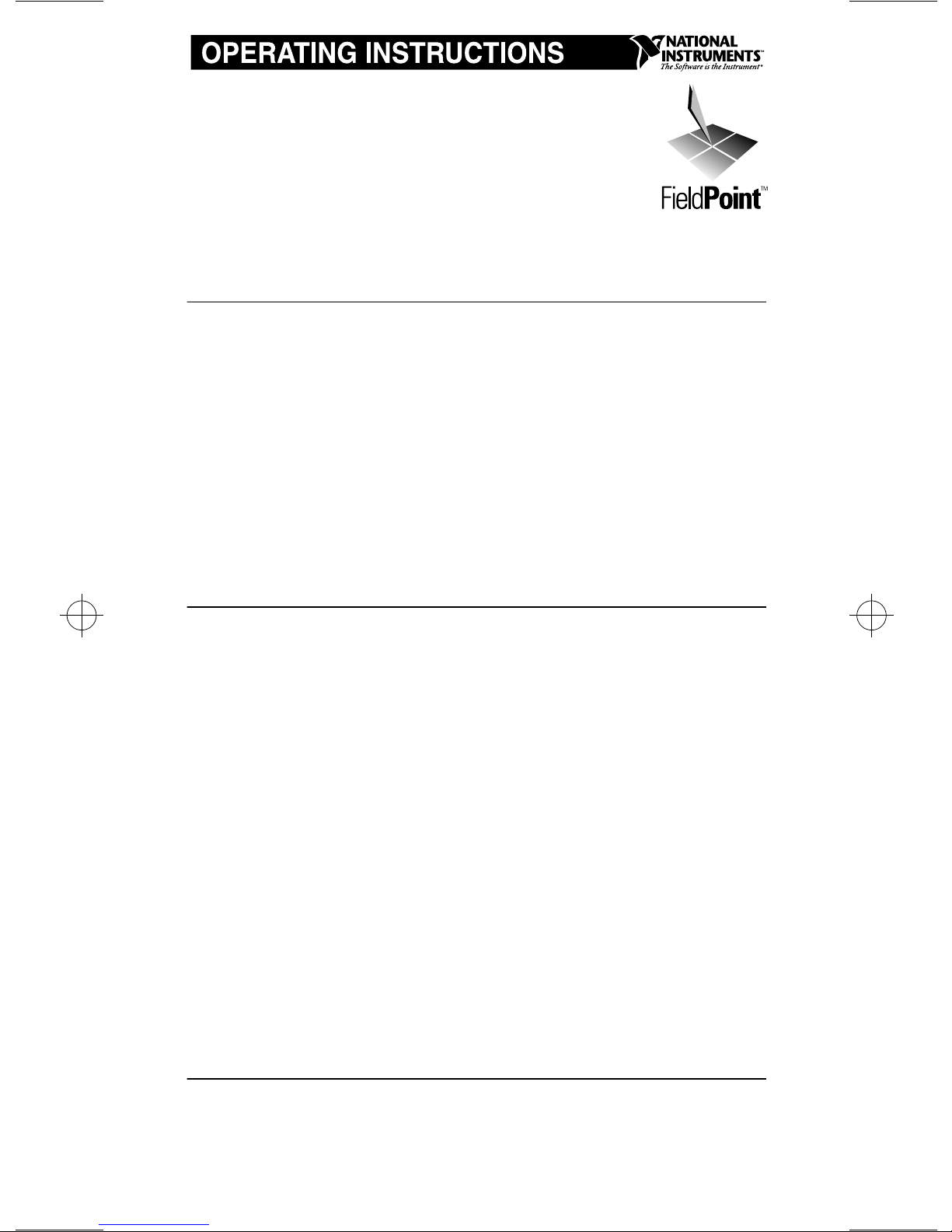
1. With a flat bladed screwdriver, open the rail clip to the
unlocked position as shown in Figure 1.
Rail Clip LockedRail Clip Unlocked
Figure 1.
DIN Rail Clip
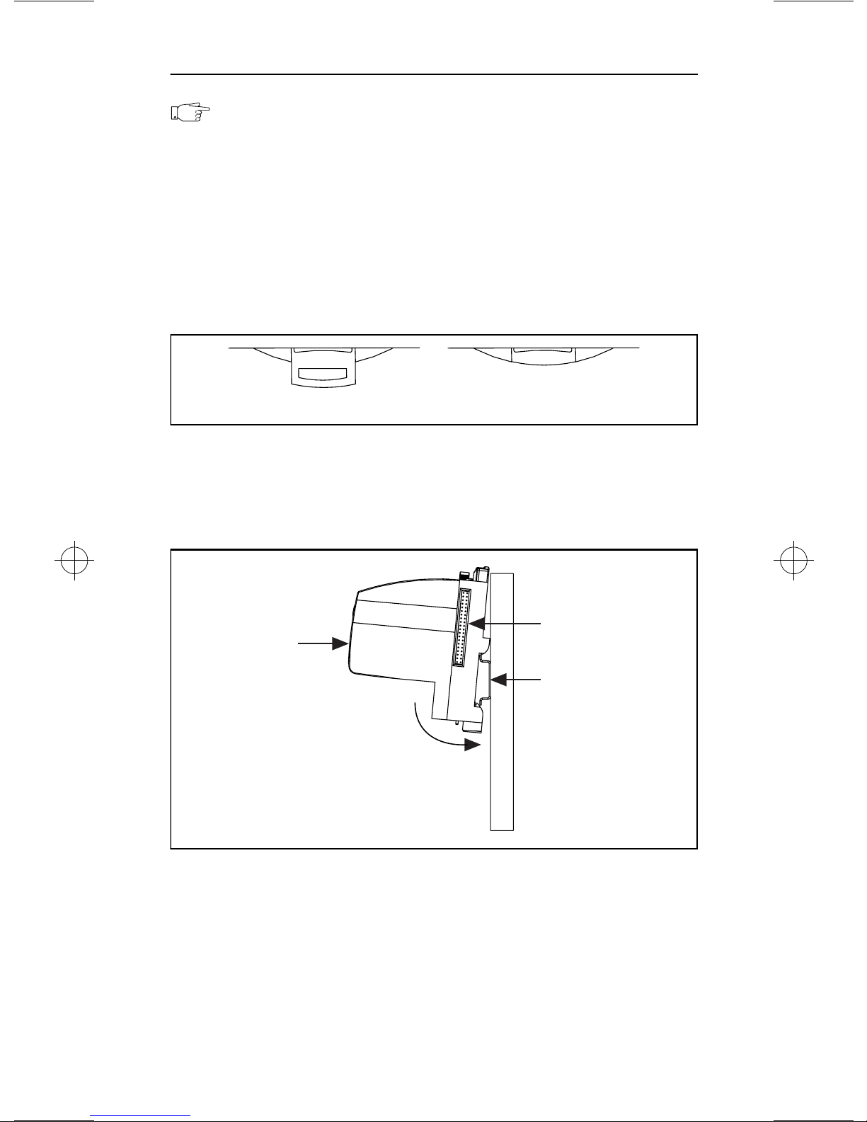
2. Hook the lip on the rear of the FP-1000 onto the top of a 35 mm
DIN rail and press the FP-1000 down onto the DIN rail as
shown in Figure 2.
Local Bus
over
Press
Connector
DIN Rail
Figure 2.
3. Slide the FP-1000 to the desired position along the DIN rail.
After the FP-1000 is in position, lock it to the DIN rail by
pushing the rail clip in.
Installing the Network Module onto a DIN Rail
2
Page 3
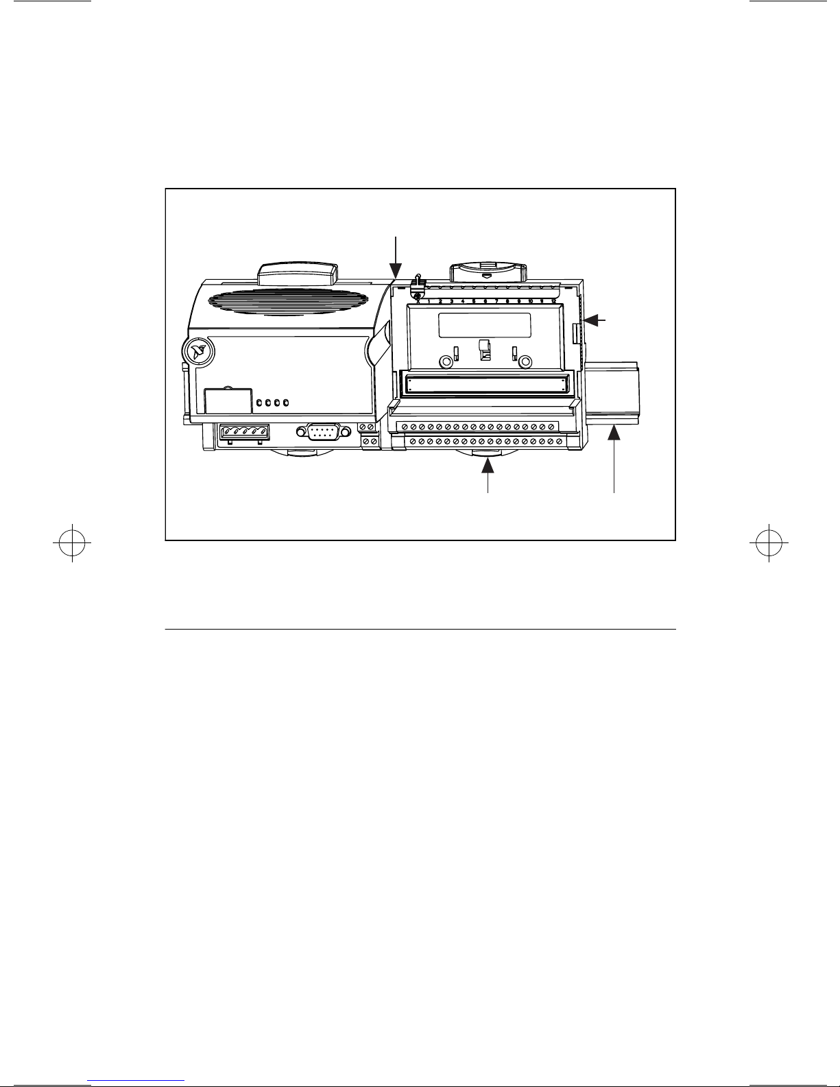
4. Add terminal bases to the DIN rail with their local bus
connectors firmly mated to the FP-1000 local bus connector.
The FP-1000 is shipped with a protective cover over the local
bus connector. Remove this protective cover, and place it over
the local bus connector of the last terminal base in the stack.
Figure 3 shows an installed FP-1000 network module.
Local Bus Connectors
Firmly Mated
Protective
Cover
Rail Snap
Locked
DIN
Rail
Figure 3. Installed Network Module
Network Connection
Connect the FP-1000 to a host computer using the 9-position DSub
RS-232 connector on the FP-1000. Connect the RS-232 port of the
FP-1000 to the RS-232 port on your computer using a male-tofemale “straight-through” cable. Do not use a “null modem” cable
(usually female-to-female). For reference, the pinout of the
RS-232 connector on the FP-1000 is shown in Figure 4.
3
Page 4
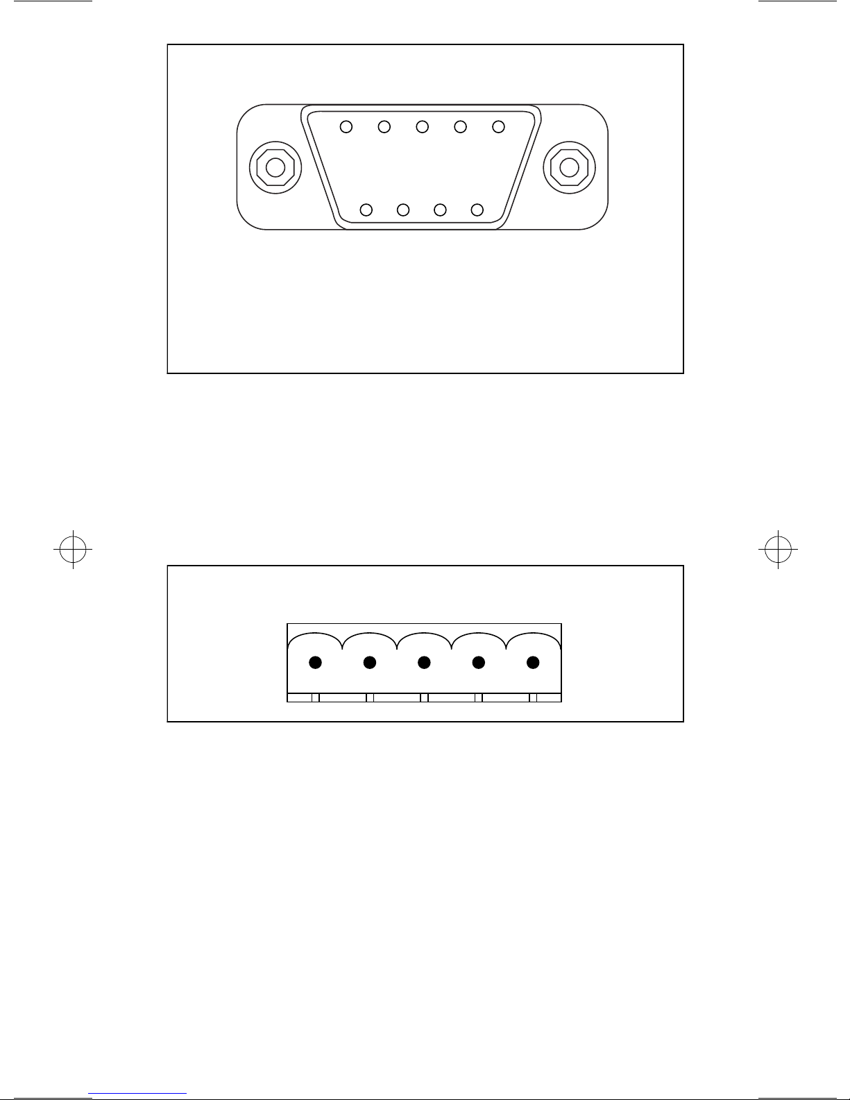
GND
NC
RX
TX
NC
54321
9876
NC
Legend:
NC = Not Connected
GND = Ground
RX = Recieve
RTS
NC
DSR
TX = Transmit
RTS = Request to Send
DSR = Data Set Ready
Figure 4. RS-232 Connector Pinout
Up to 24 additional FP-1001 network modules can be connected to
this FP-1000 module by using the built in RS-485 repeater. This
repeater makes the RS-485 port of the FP-1000 appear to the
additional FP-1001 modules as if it were an RS-485 port of the host
computer. The pinout of the RS-485 connector is shown in
Figure 5.
RX+
RX–
GND
TX–
TX+
12345
Figure 5. RS-485 Connector Pinout
The TX+ of the FP-1000 must be connected to the RX+ of all of the
FP-1001 modules, and the TX- of the FP-1000 must be connected
to the RX- of all of the FP-1001 modules. This pair of connections
provides communication from the host computer, through the
FP-1000, to the FP-1001 modules.
The RX+ of the FP-1000 must be connected to the TX+ of all of the
FP-1001 modules, and the RX- of the FP-1000 must be connected
to the TX- of all of the FP-1001 modules. This pair of connections
provides communication to the host computer, through the
FP-1000, from the FP-1001 modules.
4
Page 5

These connections are shown in Figure 6.
FP-1001 FP-1001 FP-1000
TX
120Ω
RX
120Ω
Connect the TX outputs of the FP-1001 to the RX inputs of the FP-1000,
and the RX inputs of the FP-1001 to the TX outputs of the FP-1000.
TX RX
120Ω
RX TX
120Ω
To Host
Computer's RS-232
Receive Input
From Host
Computer's RS-232
Transmit Output
Ground
Figure 6. Typical Signal Connections with One FP-1000 Connected to
Multiple FP-1001 Network Modules
Figure 6 also shows the use of 120 Ohm termination resistors. An
RS-485 network must be terminated at each end of the network, but
not anywhere else. Termination resistors should be installed
between the RX pair and between the TX pair of the FP-1000
RS-485 port. Termination resistors should also be installed on the
RS-485 port of the last FP-1001 on the network. A pair of
terminating resistors are provided with each network module. To
install them, twist the resistor leads with the RS-485 signal wires
and insert them into the RS-485 port terminals.
Setting the Address and Baud Rate
Figure 7 shows the 8-position switch on the FP-1000 network
module. Switches 1-5 set the network address, and switches 6-8 set
the baud rate. Every network module connected to one serial port
of the host computer must be given a unique address, however
modules on different serial ports may have the same address. Every
module on one serial port of the host computer must have the same
baud rate.
Switches 1-5 set the network address of the FP-1000. The
addresses of the terminal bases connected to the network module
are automatically configured to be sequentially higher than the
network module’s address. For example, if the network module is
set to address 20, the I/O module in the terminal base immediately
connected the network module is at address 21, the next I/O
5
Page 6

module is at address 22, and so on. A terminal base is assigned a
network address whether an I/O module is inserted into it or not.
Baud
Address
Rate
12345678
12345678
Switch Cover
(Removed)
Figure 7. Address and Baud Rate Switch
Table 1 shows the possible switch positions and the corresponding
address of the FP-1000.
Table 1. Network Address Switch Settings
Switch
Positions 1-5
12345678
Network Module
Address (Decimal)
0 130
Switch
Positions 1-5
12345678
Network Module
Address (Decimal)
12345678
12345678
12345678
12345678
12345678
12345678
10 140
12345678
20 150
12345678
30 160
12345678
40 170
12345678
50 180
12345678
60 190
12345678
6
Page 7

Table 1. Network Address Switch Settings (Continued)
Switch
Positions 1-5
Network Module
Address (Decimal)
Switch
Positions 1-5
Network Module
Address (Decimal)
70 200
12345678
12345678
80 210
12345678
12345678
90 220
12345678
12345678
100 230
12345678
12345678
110 240
12345678
12345678
120 Other Settings Not Allowed
12345678
Switches 6-8 set the baud rate of the FP-1000. Table 2 shows the
switch positions and the corresponding network baud rates.
Switch
Positions 6-8
12345678
12345678
12345678
12345678
Table 2. Baud Rate Switch Settings
Network Module
Baud Rate
300 19200
1200 38400
2400 57600
9600 115200
Switch
Positions 6-8
12345678
12345678
12345678
12345678
Network Module
Baud Rate
7
Page 8

Powering the FP-1000
NOTE: Terminal bases must be connected to the FP-1000,
and the baud rate switch must be set, before power is applied to
the FP-1000.
An 11-30 VDC power supply is required by each FieldPoint stack.
The network module filters and regulates this supplied power and
provides power for all the I/O modules in the stack. Therefore you
need not provide power separately to each FieldPoint I/O module
in the stack. If your field I/O device needs to be powered
separately, you can use the terminals provided on each terminal
base for such power supply connections.
The power connector is a 4-pin screw terminal connector whose
pinout is shown in Figure 8.
VV
V
11-30 VDC
Figure 8.
+
–
FP-1000 and FP-1001 Power Connector Pinout
CC
To Adjacent Terminal Base
(Optional Connection)
C
The two terminals labeled V are internally connected on the
network module, as are the two terminals labeled C. Power must be
applied to one V and C pair for operation of the FieldPoint system.
If you want to power your field I/O devices from the same power
supply, the second V and C pair provides a convenient means of
connecting power to the V and C terminals of a terminal base.
Figure 8 shows this optional connection.
8
Page 9

Specifications
Network ports ...................................1 RS-232 port, 1 RS-485
repeater port
Baud Rates........................................300, 1200, 2400, 9600,
19200, 38400, 57600,
115200 (switch selectable)
Communication parameters..............1 start bit, 8 data bits,
1 stop bit, No parity
RS-485 isolation ...............................2500 Vrms breakdown,
250 Vrms operational
Power Consumption..........................1 W + 1.15
power requirements
Operating Temperature.....................-40° C to +70° C
Storage Temperature.........................-55° C to +100° C
Relative Humidity.............................5% to 90% non-condensing
Weight...............................................250 g (8.7 oz.)
CE Mark Compliance
This product meets applicable EU directive(s) as follows:
Safety isolation ................................EN 61010 (double insulation
for 250 Vrms working
isolation, installation
category II)
EMC Directive
Immunity....................................EN 50082-1:1994
Emissions ..................................EN 55011:1991 Group I
Class A at 10 meters
*
∑
(I/O module
)
9
Page 10

Mechanical Dimensions
Figure 9 shows the mechanical dimensions of the FP-1000.
4.19 [106.4]
4.31
[109.5]
3.58 [90.9]
Figure 9.
Mechanical Dimensions
10
Page 11

Page 12

 Loading...