

Page 1
USER GUIDE
FD-11613
8-Channel Temperature Input Device for FieldDAQ
™
The FieldDAQ FD-11613 is an IP65/IP67-rated eight-channel thermocouple device that can be
networked and synchronized with IEEE 802.1AS devices. The FD-11613 supports B, E, J, K,
N, R, S, and T thermocouple types.
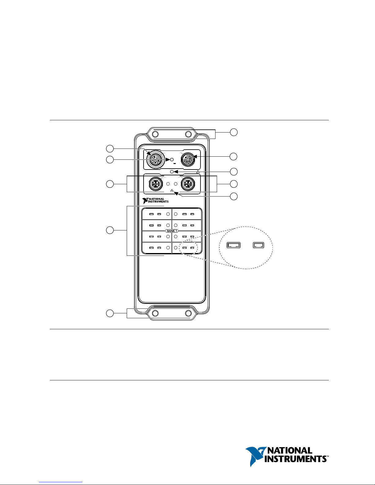
Figure 1. FD-11613 Front Panel
0
10/100/1000
LINK/ACT
FD-11613
24-Bit Thermocouple Input
SYNC
1
IN
10 A TOTAL
9-30 V
FieldDAQ
STATUS
OUT
0
2
4
6
1
3
5
7
2
6
7
1
8
3
5
5
4
TC– TC+
9
1. Power IN Connector
2. Power LED
3. Ethernet Port 0 and LED
4. Thermocouple Connectors and Open
Thermocouple LEDs
5. Mounting Holes
6. Power OUT Connector
7. STATUS LED
8. Ethernet Port 1 and LED
9. SYNC Logo
Page 2

Contents
FD-11613 Basic Information.................................................................................................... 3
Safety Guidelines...................................................................................................................... 4
Electromagnetic Compatibility Guidelines...............................................................................4
Special Conditions for Marine Applications.....................................................................5
Unpacking................................................................................................................................. 5
Hardware Symbol Definitions.................................................................................................. 5
What You Need to Get Started.................................................................................................. 6
Setting up the FieldDAQ Device.............................................................................................. 7
Power Connectors and Wiring................................................................................................ 11
Power Connectors........................................................................................................... 12
Power LED......................................................................................................................12
Wiring External Power to the FieldDAQ Device............................................................12
Thermocouple Connectors and Measurements....................................................................... 13
Thermocouple Connectors.............................................................................................. 15
Open Thermocouple LEDs............................................................................................. 15
Thermocouple Connection Guidelines............................................................................16
Programming the FieldDAQ Device...............................................................................17
Time-Based Triggers...............................................................................................................18
Timebases........................................................................................................................19
Synchronization across a Network..................................................................................20
More Information about Synchronization.......................................................................20
Ethernet Ports and Networking............................................................................................... 20
Ethernet Ports..................................................................................................................20
Ethernet LEDs.................................................................................................................21
Internal Ethernet Switch..................................................................................................22
Topology Options............................................................................................................23
External Switch Requirements........................................................................................26
Connecting to a Real-Time Controller............................................................................26
Troubleshooting Device Connectivity............................................................................ 29
Reserving the Device in MAX........................................................................................29
STATUS LED..........................................................................................................................30
Resetting the FieldDAQ to Factory-Default Settings............................................................. 30
Mounting.................................................................................................................................31
Mounting Requirements..................................................................................................33
Dimensions......................................................................................................................35
Mounting the Device Directly on a Flat Surface............................................................ 35
Alternate Mounting Configurations................................................................................ 37
Firmware................................................................................................................................. 37
Where to Go from Here.......................................................................................................... 37
Example Programs.......................................................................................................... 37
Related Documentation...................................................................................................37
Training Courses............................................................................................................. 40
Technical Support on the Web........................................................................................ 40
2 | ni.com | FD-11613 User Guide
Page 3

FD-11613 Basic Information
Kit Contents
Items in your FieldDAQ kit:
• FD-11613
• FD-11613 Quick Start
• FD-11613 Safety, Environmental, and Regulatory Information
• 1 M12 female cap for power IN connector (connected to device)
• 3 M12 male caps for power OUT and Ethernet connectors (connected to device)
Pinouts
Refer to the following topics for the connector pinouts on your FieldDAQ device:
• Thermocouple connector pinout: Refer to Thermocouple Connectors on page 15.
• Ethernet connector pinout: Refer to Ethernet Ports on page 20.
• Power connector pinout: Refer to Power Connectors on page 12.
Driver Support
Earliest driver support version for your FieldDAQ device:
Table 1. FD-11613 Driver Support
Driver Earliest Version Support
NI-DAQmx 17.6
Cables and Accessories
The following table lists some cables and accessories available for your FieldDAQ device. For
a complete list of FieldDAQ accessories and ordering information, refer to the pricing section
of the FD-11613 product page at ni.com.
Table 2. FD-11613 Cables and Accessories
Cable/Accessory Part Number
IP67 Power Supply 147464-01
PS-16 Power Supply 781094-01
M125F-Pigtail Power Cable (1 m, 2 m, 3 m lengths) 786172-01/02/03
M125F-M125M Power Cable (0.3 m, 1 m, 2 m lengths) 786173-0R3/01/02
FD-11940, Mini-TC Connector Protection Boot (Qty 8) 786394-01
FD-11613 User Guide | © National Instruments | 3
Page 4
Table 2. FD-11613 Cables and Accessories (Continued)
Cable/Accessory Part Number
SHM128M-RJ45 Ethernet Cable (1 m, 2 m, 3 m, 10 m lengths) 785944-01/02/03/10
SHM128M-SH128M Ethernet Cable (0.3 m, 1 m, 3 m lengths) 785946-0R3/01/03
M12 Torque Wrench, I/O and Ethernet 786181-01
M12 Torque Wrench, Power 786181-02
Universal M12 Male Cap, Plastic 786177-01
Universal M12 Male Cap, Metal 786178-01
Universal M12 Female Cap, Plastic 786180-01
Universal M12 Female Cap, Metal 786179-01
FD-11613 Documentation
Documents that contain information about your FieldDAQ device:
• FD-11613 Specifications
• FD-11613 Quick Start
• FD-11613 Safety, Environmental, and Regulatory Information
Safety Guidelines
Caution Do not operate the FD-11613 in a manner not specified in this user guide.
Product misuse can result in a hazard. You can compromise the safety protection
built into the product if the product is damaged in any way. If the product is
damaged, return it to National Instruments for repair.
The FD-11613 is rated for use in DRY or WET LOCATIONS. Hazardous voltages may not be
connected to the device. A hazardous voltage is a voltage greater than 42.4 V peak voltage or
60 V DC in DRY LOCATIONS, and 22.6 V peak or 35 V DC in WET LOCATIONS.
Caution All wiring must be insulated for the highest voltage used.
Electromagnetic Compatibility Guidelines
This product was tested and complies with the regulatory requirements and limits for
electromagnetic compatibility (EMC) stated in the product specifications. These requirements
and limits provide reasonable protection against harmful interference when the product is
operated in the intended operational electromagnetic environment.
4 | ni.com | FD-11613 User Guide
Page 5

This product is intended for use in industrial locations. However, harmful interference may
occur in some installations, when the product is connected to a peripheral device or test object,
or if the product is used in residential or commercial areas. To minimize interference with
radio and television reception and prevent unacceptable performance degradation, install and
use this product in strict accordance with the instructions in the product documentation.
Furthermore, any changes or modifications to the product not expressly approved by National
Instruments could void your authority to operate it under your local regulatory rules.
Notice To ensure the specified EMC performance, product installation requires
either special considerations or user-installed add-on devices.
Notice To ensure the specified EMC performance, operate this product only with
shielded Ethernet cables.
Special Conditions for Marine Applications
Some products are approved for marine (shipboard) applications. To verify marine approval
certification for a product, visit ni.com/certification and search for the certificate.
Notice In order to meet the EMC requirements for marine applications, install the
product in a shielded enclosure with shielded and/or filtered power and input/output
ports. In addition, take precautions when designing, selecting, and installing
measurement probes and cables to ensure that the desired EMC performance is
attained.
Unpacking
The FD-11613 ships in an antistatic package to prevent electrostatic discharge (ESD). ESD can
damage several components on the device.
Notice Never touch the exposed pins of connectors.
To avoid ESD damage in handling the device, take the following precautions:
• Ground yourself with a grounding strap or by touching a grounded object.
• Touch the antistatic package to a metal part of your computer chassis before removing the
device from the package.
Remove the device from the package and inspect it for loose components or any other signs of
damage. Notify NI if the device appears damaged in any way. Do not install a damaged
device.
Store the device in the antistatic package when the device is not in use.
Hardware Symbol Definitions
The following symbols are marked on your FieldDAQ device.
FD-11613 User Guide | © National Instruments | 5
Page 6
When this symbol is marked on a product, refer to Safety Guidelines for information
about precautions to take.
At the end of the product life cycle, all NI products must be disposed of according to
local laws and regulations. For more information about how to recycle NI products in
your region, visit ni.com/environment/weee.
中国客户 National Instruments 符合中国电子信息产品中限制使用某些有害物
质指令(RoHS)。关于 National Instruments 中国 RoHS 合规性信息,请登录
ni.com/environment/rohs_china。(For information about China RoHS
compliance, go to ni.com/environment/rohs_china.)
What You Need to Get Started
You will need the following items to set up your FieldDAQ device.
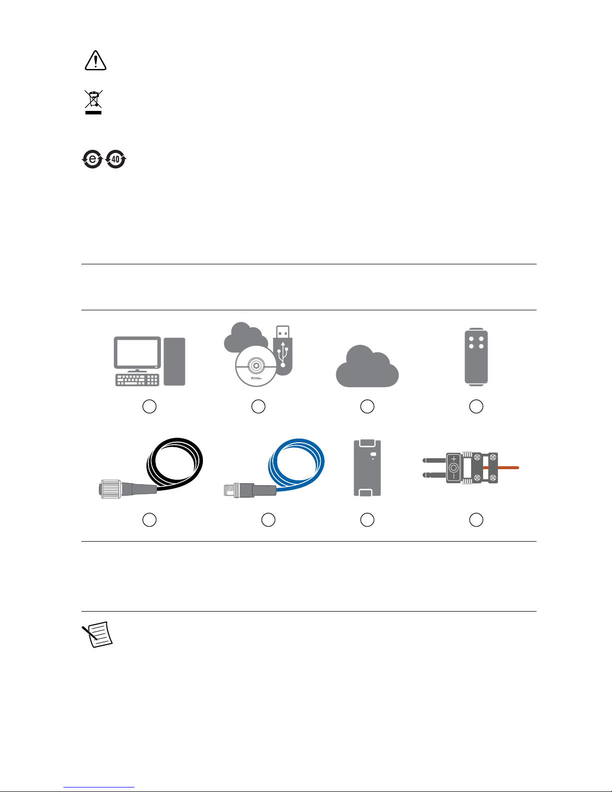
Figure 2. FieldDAQ Installation Supply List
21
7
3
NI-DAQmx
4
865
1. Host Computer running Windows
2. Application Software
3. NI-DAQmx Driver
4. FieldDAQ Device
5. 5-pin L-coded M12 Power Input Cable
6. 8-pin X-coded M12 Ethernet Cable
7. External Power Supply
8. B, E J, K, N, R, S, and/or T Thermocouples with
Mini TC Connectors
Note You can either use a shielded straight-through Ethernet cable or an Ethernet
crossover cable to connect the FieldDAQ device directly to your computer.
6 | ni.com | FD-11613 User Guide
Page 7

Setting up the FieldDAQ Device
Complete the following steps.
1. Install the application software (if applicable), as described in the installation instructions
that accompany your software. Check your driver and application development
environment (ADE) readme files for specific version compatibility.
2. Install NI-DAQmx from ni.com/downloads/drivers. Complete the instructions.
3. Register your NI hardware online at ni.com/register when prompted. The last dialog box
opens with the following options:
• Restart Later to install more NI software or documentation.
• Shut Down or Restart if you are ready to install your device.
If you have problems installing your software, go to ni.com/support/daqmx.
4. (Optional) Mount the FieldDAQ device to a panel, as described in Mounting.
5. Plug the thermocouple into a thermocouple input. Refer to Thermocouple Connectors for
information about thermocouple signal connections and guidelines.
6. Carefully align and connect one end of the Ethernet cable to Ethernet port 0 on the
device, and the other end directly to your computer or any network connection on the
same subnet as your computer.
7. Power the device by carefully aligning and connecting the power IN port on FieldDAQ to
an external 9 V DC to 30 V DC power source with the 5-pin L-coded M12 power cable.
For information about wiring your external power source to the power connector, refer to
Wiring External Power to the FieldDAQ Device. The FieldDAQ device requires an
external power supply that meets the specifications listed in the FD-11613 Specifications.
The Power LED lights. Refer to Power LED for information about Power LED status.
8. To add the FieldDAQ to your software configuration, open NI MAX on your Windows
host computer. Expand Devices and Interfaces»Network Devices.
FD-11613 User Guide | © National Instruments | 7
Page 8
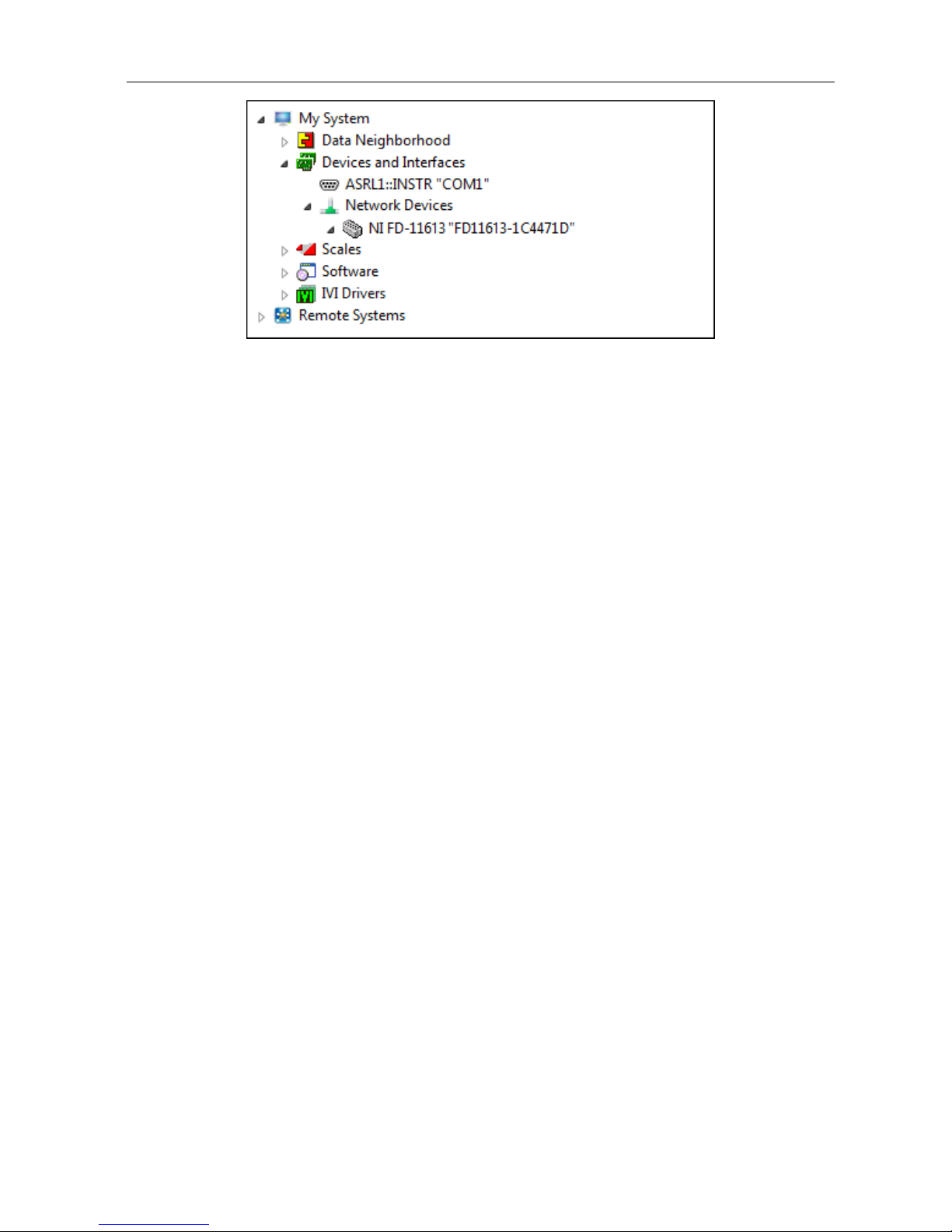
Figure 3. Network Devices in MAX
• If the device is on your local subnet, the device automatically appears in the list of
available devices. Right-click the FieldDAQ device and select Add Device.
• If the device is not on your local subnet, right-click Network Devices and select
Find Network NI-DAQmx Devices.
9. In the Find Network NI-DAQmx Devices dialog box that opens, do one of the following:
• Check the box that corresponds to your device in the Hostname column.
8 | ni.com | FD-11613 User Guide
Page 9
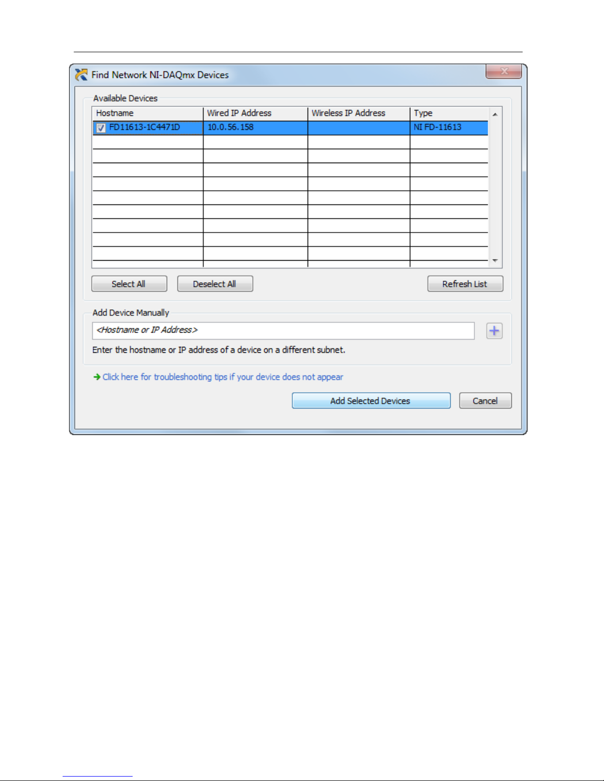
Figure 4. Find Network NI-DAQmx Devices
• If you know the device IP address, such as 192.168.0.2, enter it into the Add Device
Manually field of the Find Network NI-DAQmx Devices window, and click the +
button.
• Enter the hostname of the device. The default hostname is FD11613-<serial
number>.
10. Click Add Selected Devices.
The FieldDAQ device icon changes from white to dark grey, indicating that it is
recognized and present on the network.
FD-11613 User Guide | © National Instruments | 9
Page 10

Figure 5. MAX Icons and States
1
2
1. Discovered, but Not Added to the Network
2. Recognized, Present, and Reserved on the Network
If your device does not appear in Available Devices, click Refresh List. If the device still
does not appear, try the following:
• If you connected the FieldDAQ device directly to your computer, ensure your
network card is configured to obtain an IP address automatically, then click Refresh
List.
Note If you connected the FieldDAQ device directly to your computer,
the setup time may be longer. Wait 30 to 60 seconds after the STATUS
LED turns off, then click Refresh List.
• Contact your system administrator to confirm that the network is working and that a
firewall is not interfering with discovery. For additional troubleshooting resources
for the FieldDAQ device, refer to the Troubleshooting Device Connectivity in this
guide and the Finding a Network DAQ Device in MAX topic in the Measurement &
Automation Explorer Help for NI-DAQmx.
11. If the FieldDAQ device is not reserved automatically, select the device and click the
Reserve Network Device button. Refer to Reserving the Device in MAX for more
information.
12. Self-test your device in MAX by expanding Devices and Interfaces»Network Devices,
right-clicking your FieldDAQ device, and selecting Self-Test. Self-test performs a brief
test to determine successful device installation. When the self-test finishes, a message
indicates successful verification or if an error occurred. If an error occurs, refer to ni.com/
support/daqmx.
13. Run a Test Panel in MAX by expanding Devices and Interfaces»Network Devices»your
FieldDAQ device, right-clicking the bank of connectors in your FieldDAQ device, and
selecting Test Panels. If the test panel displays an error message, refer to ni.com/support.
Click Close to exit the test panel.
Note When in use, the FieldDAQ device may become warm to the touch. This is
normal.
Note M12 connectors must be mated to cables or have caps installed on them to
meet IP65/IP67 requirements. Cover the unused connectors with the included plastic
caps whenever water, dust, or dirt are present.
10 | ni.com | FD-11613 User Guide
Page 11
Note Avoid long periods of exposure to sunlight.
For instructions on networking to a real-time controller, refer to Connecting to a Real-Time
Controller.
Power Connectors and Wiring
The FieldDAQ device has two 5-pin L-coded M12 power connectors, power IN and power
OUT. The power connectors provide one voltage line (V), one common line (C), chassis
ground, and two lines for optional auxiliary power, Aux1 and Aux2.
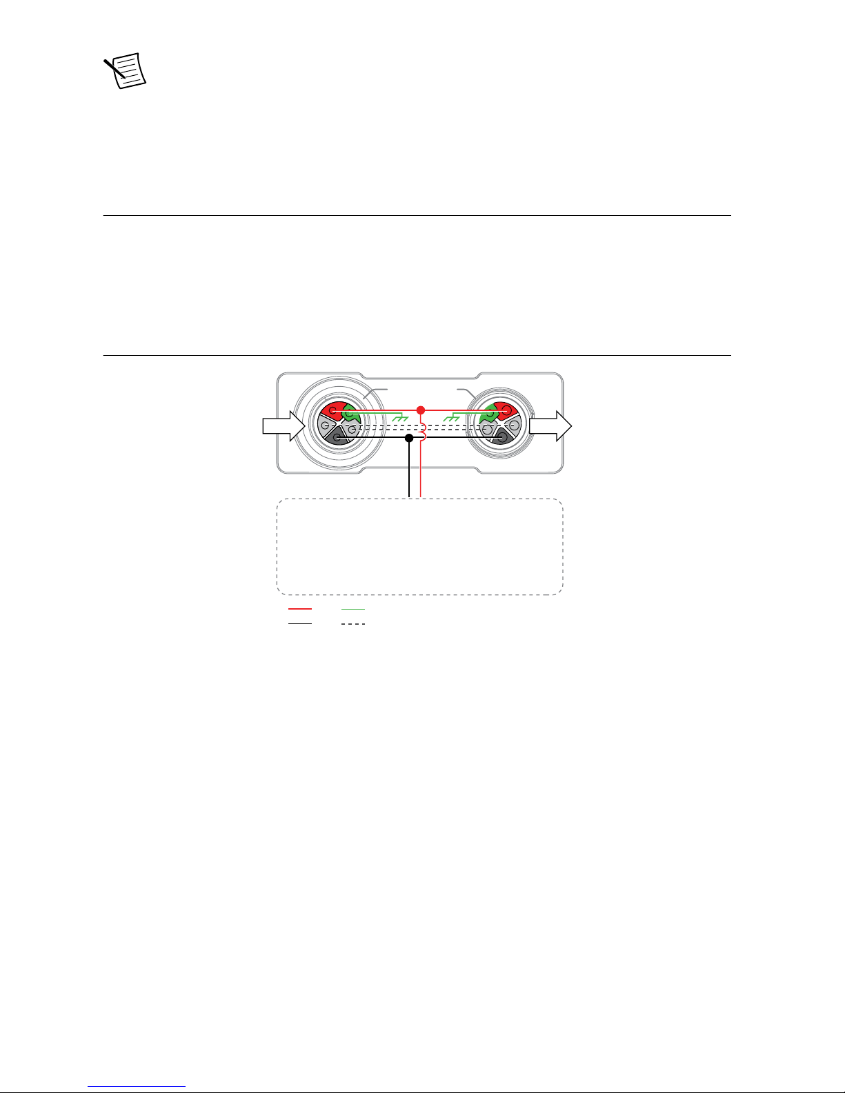
The following figure shows the power circuitry on the FieldDAQ device.
Figure 6. Power Circuitry
IN OUT
Chassis Ground
Internal Circuit
Aux
V
C
The FieldDAQ device requires an external power source as described in Power Requirements
in the FD-11613 Specifications. Recommended NI power supplies are listed in FD-11613
Basic Information.
The FD-11613 has a maximum device power consumption of 4.9 W. Each FieldDAQ filters
and regulates the supplied power for its tasks.
When FieldDAQ devices are linked together through the power IN and power OUT
connectors, the total current consumption of the chain equals the sum of every linked
FieldDAQ device’s current consumption. The total current cannot exceed 10 A, and the total
supply load of the chain must be less than 300 W.
You can use the optional auxiliary power lines (Aux1 and Aux2) to draw power for
non-FieldDAQ devices in your network. If you are connecting power through the auxiliary
power lines, ensure that the total combined current between V Input and Aux power lines does
not exceed 10 A.
FD-11613 User Guide | © National Instruments | 11
Page 12
Refer to the FD-11613 Specifications for information about the power connectors, power
requirements, and current limits of your FieldDAQ device.
Cap the power connectors when not in use.
Power Connectors
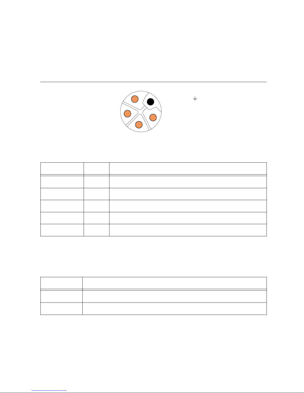
The following figure shows the pinout of the Power IN connector.
Figure 7. Power Connector Pinout
Aux1
C
V
Chassis Ground ( )
Aux2
2
3
4
5
1
Table 3. Signal Descriptions
Pin Number Signal Description
1 V Positive voltage line
2 Aux2 Optional line for powering non-FieldDAQ devices
3 C Common. Negative voltage line
4 Aux1 Optional line for powering non-FieldDAQ devices
5 — Chassis Ground
Power LED
The green POWER LED on the front panel identifies when the device is powered.
Table 4. LED State/Device Status
LED State Device Status
On Device is receiving adequate power for its tasks.
Off Device is unpowered or receiving inadequate power.
Wiring External Power to the FieldDAQ Device
Complete the following steps to connect a power source to the FieldDAQ device.
1. Verify the power source is turned off.
12 | ni.com | FD-11613 User Guide
Page 13

2. If you are not using a pre-assembled cable, complete the following steps.
a) Connect the positive lead of the primary power source to the V terminal (pin 1)
inside the power connector plug.
b) Connect the negative lead of the primary power source to the C terminal (pin 3)
inside the power connector plug.
c) (Optional) To power non-FieldDAQ devices through the power network, connect the
leads of an additional auxiliary power source to the Aux1 (pin 4) and Aux2 (pin 2)
terminals inside the power connector plug.
d) Assemble the rest of the plug sleeve.
3. Carefully align and connect the cable to the external power source and the power IN
connector on the FieldDAQ device.
4. Turn on the external power source.
If the power source is connected to the power connector using long wiring with high DC
resistance, the voltage at the power connector may be significantly lower than the specified
voltage of the power source.
Refer to Power Requirements in the FD-11613 Specifications for information about the power
supply input range. Refer to Safety Voltages in the FD-11613 Specifications for information
about the maximum voltage from terminal to chassis ground.
Thermocouple Connectors and Measurements
The following figure shows thermocouple circuitry of the FD-11613.
FD-11613 User Guide | © National Instruments | 13
Page 14

Figure 8. FD-11613 Block Diagram
TC0+
TC0–
TC7+
TC7–
5.34 MΩ
Input
Impedance
Open
Thermocouple
Detection
Current
Isolated
ADC
Filter
ISOLATION
Ethernet Ports
Ethernet Switch
Digital Logic
5.34 MΩ
Input
Impedance
Open
Thermocouple
Detection
Current
Isolated
ADC
Filter
Hardware
Data
The FD-11613 provides channel-to-channel isolation.
• Input Impedance—Each channel has a resistor that produces an input impedance
between the TC+ and TC- terminals. The gain and offset errors resulting from the source
impedance of connected thermocouples are negligible for most applications.
Thermocouples with a higher lead resistance can introduce more significant errors.
• Open Thermocouple Detection—Each channel has an open thermocouple detection
(OTD) circuit, which consists of a current source between the TC+ and TC- terminals. If
an open thermocouple is connected to the channel, the current source forces a full-scale
voltage across the terminals and the Open Thermocouple LED lights red.
Refer to the Open Thermocouple Detection (OTD) topic in the NI-DAQmx Help for more
information about how this feature is used in the NI-DAQmx API.
14 | ni.com | FD-11613 User Guide
Page 15

• Timing Modes—The FD-11613 supports the following timing modes:
– High-resolution optimizes accuracy and noise and rejects power line frequencies.
– Best 50 Hz rejection optimizes 50 Hz noise rejection.
– Best 60 Hz rejection optimizes 60 Hz noise rejection.
– High-speed optimizes sample rate and signal bandwidth.
Refer to the FieldDAQ Timing Considerations topic in the NI-DAQmx Help for more
information about configuring timing in the NI-DAQmx API.
• Filter, Differential Amplifier, and ADC—Each channel simultaneously passes through
a filtered, differential amplifier before being sampled by a 24-bit ADC.
The FieldDAQ device provides overvoltage protection for each channel; refer to the FD-11613
Specifications for more information about overvoltage protection.
Thermocouple Connectors
The FD-11613 features eight thermocouple connectors. The following figure shows the pinout
of a thermocouple connector.
Figure 9. FD-11613 Pinout and Open Thermocouple LED
0
TC– TC+
Table 5. Signal Descriptions
Signal Description
TC- Negative thermocouple terminal
TC+ Positive thermocouple terminal
Open Thermocouple LEDs
Each thermocouple connector has an open thermocouple LED.
FD-11613 User Guide | © National Instruments | 15
Page 16

Table 6. LED State/Thermocouple Status
LED Color and State Thermocouple Status
Red, solid Open thermocouple detected
Green, solid Thermocouple connected
Yellow, blinking/
alternating
User-defined status. Use MAX to write a state to any LED by
expanding Devices and Interfaces»Network Devices»your
FieldDAQ device»bank of connectors in your FieldDAQ
device and configuring the LED settings on the Settings tab.
Note When you turn off the LEDs in MAX, the FieldDAQ device controls and sets
the state of the LED. You cannot configure an LED while a task is running.
Thermocouple Connection Guidelines
The following figure shows a general connection diagram.
Figure 10. Connection Diagram
Thermocouple
TC-
TC+
Notice To protect against ESD, water, and dirt, install FD-11940, Mini-TC
Connector Protection Boot (Qty 8) (NI part number 786394-01) on the mini-TC
plugs.
Make sure that devices you connect to the FD-11613 are compatible with the device
specifications. Refer to your thermocouple documentation or the thermocouple wire spool to
determine which wire is the positive lead and which wire is the negative lead.
Minimizing Thermal Gradients
Changes in the ambient air temperature near the front connector or a thermocouple wire
conducting heat directly to terminal junctions can cause thermal gradients. Observe the
following guidelines to minimize thermal gradients and improve the system accuracy.
• Use small-gauge thermocouple wire. Smaller wire transfers less heat to or from the
terminal junction.
• Run thermocouple wiring together to keep the wires at the same temperature.
• Avoid running thermocouple wires near hot or cold objects.
• Minimize adjacent heat sources and air flow across the terminals.
• Keep the ambient temperature as stable as possible.
• Make sure the FieldDAQ device terminals are facing forward or upward.
• Keep the FieldDAQ device in a stable and consistent orientation.
16 | ni.com | FD-11613 User Guide
Page 17

• Allow the thermal gradients to settle after a change in system power or in ambient
temperature. A change in system power can happen when the system powers on, or you
add or remove devices from a network topology.
• Allow the thermal gradients to settle after plugging or unplugging the mini-TC plugs.
Thermocouple Measurement Accuracy
Thermocouple measurement errors depend partly on the following factors:
• Type of thermocouple
• Accuracy of the thermocouple
• Temperature that you are measuring
• Resistance of the thermocouple wires
• Cold-junction temperature
For the best accuracy performance, set up the FD-11613 according to Setting up the FieldDAQ
Device and Thermocouple Connection Guidelines to minimize thermal gradients across the
terminals.
Programming the FieldDAQ Device
You can use the FieldDAQ device in the following analog input applications:
• Single-point acquisition
• Finite acquisition
• Continuous acquisition
The FieldDAQ device features the following timing and triggering signals:
• AI Sample Clock Signal
• AI Sample Clock Timebase Signal
• AI Start Trigger Signal
For more information about programming analog input applications and triggers in software,
refer to the NI-DAQmx Help or the LabVIEW Help for more information.
AI Sample Clock Signal
A sample consists of one reading from each channel in the AI task. Sample Clock signals the
start of a sample of all analog input channels in the task. Refer to the following figure for
sample clock source options.
Figure 11. AI Sample Clock Timing Options
Programmable
Clock
Divider
AI Sample Clock
Timebase
AI Sample
Clock
80 MHz Timebase
20 MHz Timebase
100 kHz Timebase
FD-11613 User Guide | © National Instruments | 17
Page 18

The FD-11613 is specifically designed for measuring signals that vary slowly. Because of their
slow rate, it is not appropriate for these devices to constrain the AI Sample Clock to operate at
or slower than their maximum rate. When using the FD-11613 in the same task as faster
devices, the maximum Sample Clock rate can run faster than the maximum rate for the device.
When operating at a rate faster than the it can support, the FD-11613 returns the same point
repeatedly, until a new conversion completes. In a hardware-timed task, the first point is
acquired when the task is committed. The second point is acquired after the start trigger as
shown in the following figure.
Figure 12. Sample Clock Timing Example
Start Trigger
Data from
A/D Conversion
Sample Clock
Data Returned
to AI Task
1st A/D Conversion 2nd A/D Conversion 3rd A/D Conversion
A
B C
A A A B B B C
AI Sample Clock Timebase Signal
The AI Sample Clock Timebase signal is divided down to provide a source for Sample Clock.
AI Start Trigger Signal
Use the Start Trigger signal to begin a measurement acquisition. A measurement acquisition
consists of one or more samples. If you do not use triggers, begin a measurement with a
software command. Once the acquisition begins, configure the acquisition to stop in one of the
following ways:
• In finite mode, when a certain number of points has been sampled
• In continuous mode, with a software command
You can specify a default delay from the Start Trigger to the first sample.
Use the Start Trigger signal with a time source, by specifying a specific time in NI-DAQmx.
Refer to the Time Triggering topic in the NI-DAQmx Help for more information on accessing
time-based features in the NI-DAQmx API.
Time-Based Triggers
FieldDAQ devices feature automatic network-based synchronization with compatible
networks and 802.1AS-capable NI Linux Real-Time controllers. The SYNC logo on the
device front panel indicates that the device is capable of hardware-based synchronization over
a network.
18 | ni.com | FD-11613 User Guide
Page 19

The device can be daisy-chained to each other or connected to external networks that support
802.1AS synchronization, and all device timebases will be automatically synchronized. Refer
to Synchronization across a Network for more information about supported topologies and
other technical requirements.
Network-synchronized devices can also take advantage of time-based synchronization features
in NI-DAQmx. Certain triggers can be specified in terms of time of day. Time-based triggers
and multidevice tasks (spanning multiple network-synchronized FieldDAQ devices) can help
simplify programming for large systems.
Time triggers can be specified in Host Time or I/O Device Time, depending on the needs of
your application.
• I/O Device Time—The time the FieldDAQ device uses internally. This time is
determined by the network configuration and is shared by all 802.1AS
network-synchronized devices on your subnet.
• Host Time—The time on your computer or NI Linux Real-Time controller. This is
usually the current global time, and is provided by a local real-time clock or a network
time protocol (NTP) server.
NI-DAQmx automatically translates from Host Time to I/O Device Time as necessary. The
accuracy of this translation depends on the relationship between these times and can reduce the
relative accuracy of time triggers across multiple devices. For maximum accuracy, use an
NI Linux Real-Time controller as the host in a supported topology. However, NI-DAQmx
guarantees that two tasks configured to start at the same host time always start at the same
I/O Device Time in all scenarios, preserving precise synchronization between chassis in this
common use case. Refer to the Time Triggering topic in the NI-DAQmx Help for more
information on accessing time-based features in the NI-DAQmx API.
Timebases
The following figure shows the FD-11613 clock routing circuitry and timebases.
Figure 13. Clock Routing Circuitry
÷ 4
÷ 200
80 MHz Timebase
100 kHz Timebase
20 MHz Timebase
Clock
Generator
Onboard
100 MHz
Oscillator
You can use the 80 MHz, 20 MHz, and 100 kHz timebases to generate the measurement
signals. The 80 MHz timebase is generated directly from the onboard clock generator. The
20 MHz and 100 kHz timebases are generated by dividing down the 80 MHz timebase.
Refer to the FieldDAQ Timing Considerations and Master Timebase Synchronization topics in
the NI-DAQmx Help for more information about configuring timing in the NI-DAQmx API.
FD-11613 User Guide | © National Instruments | 19
Page 20

Synchronization across a Network
The onboard 100 MHz oscillator automatically synchronizes to other network-synchronized
devices that are part of your local 802.1AS subnet.
The 80 MHz, 20 MHz, and 100 kHz Timebases are derived from the oscillator, and are
synchronized to it. Therefore, they are also synchronized to other network-synchronized
timebases on your 802.1AS subnet. This enables measurement signals to be synchronized to
other devices across a distributed network.
The FieldDAQ devices use the IEEE 802.1AS protocol over the network to synchronize.
These devices cannot synchronize over the network with devices that use protocols or
IEEE 1588 profiles other than IEEE 802.1AS.
More Information about Synchronization
The following documents will help you overcome typical hurdles in getting started with
synchronized measurements:
• Synchronizing analog input FieldDAQ devices with NI-DAQmx in LabVIEW—Visit
ni.com/info and enter fdaisync.
• Designing Ethernet measurement systems for synchronization, considering
topologies, masters, and third party devices—If topology changes result in a device’s
master changing, executing tasks may be affected. Visit ni.com/info and enter fdenet.
• How to achieve high accuracy measurements—Visit ni.com/info and enter fdsync.
• Synchronization accuracy explained—Visit ni.com/info and enter syncacc.
Ethernet Ports and Networking
The Ethernet Network Interface transfers data between the FieldDAQ device and the network.
It gathers the data into TCP/IP packets that can be sent across the network and interpreted by
the host.
Note Refer to Setting up the FieldDAQ Device or Connecting to a Real-Time
Controller for information about connecting the FieldDAQ device to a host
computer or host real-time controller.
Ethernet Ports
The FieldDAQ devices has two 8-pin X-coded M12 Ethernet ports—0 and 1. You can use a
shielded straight-through Ethernet or an Ethernet crossover cable with either of the Ethernet
ports to network your device to a computer host, NI Linux Real-Time controller, another
FieldDAQ device, or any network connection on the same subnet. Refer to Topology Options
for more information about using these ports in various topologies.
20 | ni.com | FD-11613 User Guide
Page 21

Figure 14. Ethernet Connector Pinout
8
7
6
2
1
3
4
5
Table 7. Signal Descriptions
Pin Number Wire Color Gigabit Ethernet Signal Fast Ethernet Signal
1 Orange/White BI_DA+ TX+
2 Orange BI_DA- TX-
3 Green/White BI_DB+ RX+
4 Green BI_DB- RX-
5 Brown/White BI_DD+ No Connect
6 Brown BI_DD- No Connect
7 Blue/White BI_DC+ No Connect
8 Blue BI_DC- No Connect
You can use the Ethernet ports to reset the FieldDAQ device to factory-default settings. Refer
to Resetting the FieldDAQ to Factory-Default Settings for more information.
Cap the Ethernet ports when not in use.
Ethernet LEDs
Each Ethernet port has a green LED that indicates network activity and link speed.
Table 8. LED State/Device Status
LED State Device Status
On Ethernet link
Blinking, fast (12 blinks/s) Ethernet activity. Connected at 1,000 Mbit/s.
Blinking, moderate (6 blinks/s) Ethernet activity. Connected at 100 Mbit/s.
FD-11613 User Guide | © National Instruments | 21
Page 22

Table 8. LED State/Device Status (Continued)
LED State Device Status
Blinking, slow (3 blinks/s) Ethernet activity. Connected at 10 Mbit/s.
Off No Ethernet connection
Internal Ethernet Switch
The FieldDAQ device features a full hardware-accelerated internal Ethernet switch for greater
performance, wiring flexibility, and compatibility over standard Ethernet ports. The Ethernet
switch exposes two Ethernet ports to the user. Either port can be used to connect the device to
the network. The two ports can be used to connect multiple devices in a daisy-chain topology.
The switch also supports the Rapid Spanning Tree Protocol (RSTP) algorithm, enabling ring
topologies. Refer to Topology Options for more details.
IEEE 802.1AS-2011 Precision Time Protocol
The internal Ethernet switch is an 802.1AS time-aware bridge, compatible with the
IEEE 802.1AS-2011 Precision Time Protocol. It can synchronize local measurement signals to
other devices across an 802.1AS subnet. It can also serve as a bridge, synchronizing 802.1AS
devices that are attached to each of the two ports. Refer to Synchronization across a Network
for more details.
Note FieldDAQ devices use the IEEE 802.1AS protocol over the network to
synchronize. The IEEE 802.1AS protocol is an IEEE 1588 profile, but is
incompatible with other IEEE 1588 profiles. These FieldDAQ devices cannot
synchronize over the network with devices that use protocols or IEEE 1588 profiles
other than IEEE 802.1AS.
IEEE 802.1Q-2014 Rapid Spanning Tree Protocol (RSTP)
It is possible to create loops in a network using the FieldDAQ device. To prevent these loops
from disrupting the network, the FieldDAQ device implements the IEEE 802.1Q-2014 Rapid
Spanning Tree Protocol (RSTP). Using this protocol, each FieldDAQ device is able to find the
shortest path for incoming packets to reach the rest of the network. When multiple paths exist,
this adds a form of redundancy. If a link fails, the protocol automatically switches to use the
redundant link. This process can take several seconds in some cases.
To gain these benefits on external switches connected to the FieldDAQ device, 802.1w
(RSTP) must be enabled. All external switches must be configured to allow the FieldDAQ
device to transmit 802.1w packets, known as Bridge Protocol Data Units (BPDU). If any
switch has a feature—such as “BPDU guard”—enabled, the port connected to the FieldDAQ
device is disabled and communication is lost. Refer to the documentation for your external
switch for information about enabling RSTP and disabling BPDU guards on the switch.
22 | ni.com | FD-11613 User Guide
Page 23

FieldDAQ MAC Addresses
The FieldDAQ device is associated with two MAC addresses—both of which are labeled on
the device—device and switch. These MAC addresses are not associated with a particular
Ethernet port, but both addresses can appear on both ports as necessary.
Table 9. NI MAX Device and Switch MAC Addresses
Device MAC Address Switch MAC Address
Associated with the device’ IP
address
Associated with the internal Ethernet switch—not
associated with the device’s IP address
Used by normal device traffic Used for Ethernet protocols for network configuration
and synchronization
Listed in MAX Not listed in MAX
The switch MAC address is used to implement the following switch protocols:
• IEEE 802.1AS-2011 (Precision Time Protocol)
• IEEE 802.1Q-2014 (Rapid Spanning Tree Protocol [RSTP] implemented)
The switch MAC address only appears in packets exchanged between the switch embedded in
the FieldDAQ device and the next Ethernet device. It will not propagate further in a properly
configured network. For more information about the recommended configurations for
networking the FieldDAQ device, refer to Topology Options.
Topology Options
Recommended networking topologies are described in this section.
• Host—Can be a computer or a real-time controller with the NI Linux Real-Time
operating system, such as the IC-317x, cRIO-9035/9039 Sync, cRIO-904x, or
cDAQ-9132/9133/9134/9135/9136/9137 for LabVIEW Real-Time
• Node—Can be any FieldDAQ device or 802.1AS-compliant CompactDAQ chassis, such
as the cDAQ-9185/9189
For more information about designing Ethernet measurement systems, visit ni.com/info and
enter fdenet.
Line Topology
In a line topology—also known as daisy-chaining or bus topology—the host communicates
directly with all nodes through one bus line. A standard Ethernet device or switch can be
added to the end of the chain if desired and used as normal. Be aware that these devices will
compete for network bandwidth with the FieldDAQ device. Reliable system design requires
awareness of the bandwidth consumed by each device during operations. This topology offers
no redundant links.
FD-11613 User Guide | © National Instruments | 23
Page 24

Figure 15. Line Topology
Networking
Node Node Node
Host
Advantages:
• Simple and inexpensive installation, expansion, and troubleshooting
• Ideal for low number of nodes. NI recommends a maximum of 15 nodes.
• No external switch needed
• Can cover long distances
Disadvantages:
• Any unpowered nodes and/or node failure disrupts network communication
• Addition or removal of any node disrupts network communication
• Failure of any Ethernet cable and/or improper cable termination disrupts network
communication
• Network performance and synchronization affected when node count exceeds 15.
Consider the Star Topology for systems that require a greater number of nodes.
Note For information about daisy-chaining power, refer to Power Connectors and
Wiring.
Ring Topology
In a ring topology, the host communicates with all nodes through the most effective path. You
must use an external switch in a ring topology. You must configure the network properly with
a recommended external switch before creating redundant links in the network. Refer to
External Switch Requirements for information about what to look for in an external switch.
Figure 16. Ring Topology
Node Node Node
Networking
Host
External
Switch
Advantages:
• Failure of any single Ethernet cable does not disrupt network communication
• Additional nodes or heavier network traffic affects network performance less than the line
topology
24 | ni.com | FD-11613 User Guide
Page 25

• Simple installation
• Ideal for a local networking solution
Note Network configuration and programming require careful consideration. Visit
ni.com/info and enter fdenet for information about exploiting link redundancy and
automatically improving reliability.
Disadvantages:
• Network traffic patterns can make troubleshooting difficult
• Requires an external switch
Note For information about daisy-chaining power, refer to Power Connectors and
Wiring.
Star Topology
In a star topology, the host communicates directly with each node through the external switch.
You must use an external switch in a star topology; for network synchronization, you must use
an external 802.1AS switch. Redundant links are recommended, but optional, in this topology.
You must configure the network properly with a recommended external switch before creating
redundant links in the network. Refer to External Switch Requirements for information about
what to look for in an external 802.1AS switch.
Figure 17. Star Topology
Node
Node
Node
Host
Networking
Redundant Link (optional)
External
Switch
Advantages:
• Unpowered nodes and/or node failure does not disrupt network communication with
other nodes
• Failure of any single Ethernet cable does not disrupt network communication when you
have a redundant link
FD-11613 User Guide | © National Instruments | 25
Page 26

• Additional nodes or heavier network traffic affects network performance less than the
other topologies
• Simple installation, expansion, and troubleshooting
Note Network configuration and programming require careful consideration. Visit
ni.com/info and enter fdenet for information about exploiting link redundancy and
automatically improving reliability.
Disadvantages:
• Most costly of the recommended topologies
• Requires an external switch (external 802.1AS switch for network synchronization)
• Covers the least distance
Note For information about daisy-chaining power, refer to Power Connectors and
Wiring.
Other Topologies
For information about designing Ethernet measurement systems for synchronization, visit
ni.com/info and enter fdenet.
External Switch Requirements
To meet the minimum requirements for successful operation with FieldDAQ devices, any
switch directly connected to the FieldDAQ device should be compliant with
IEEE 802.1Q-1998 bridges and bridged networks.
To take advantage of the network synchronization and network redundancy features of the
FieldDAQ device, ensure that your network infrastructure meets certain requirements:
• IEEE 802.1AS-2011 time-based synchronization support—Automatically
synchronizes timebases and enables the use of time-based triggers and multi-device tasks
between device across the network.
• IEEE 802.1Q-2014 (Rapid Spanning Tree Protocol) support—Supports network
redundancy functionality in ring and star topologies
– Rapid Spanning Tree Protocol (RSTP) enabled
– Bridge Protocol Data Units (BPDU) Guard disabled
To learn more about recommended network switches and other network configuration best
practices and requirements, visit ni.com/info and enter fdenet.
Connecting to a Real-Time Controller
You can use the FieldDAQ device as expansion I/O from certain NI Linux Real-Time
controllers. Discover and configure the NI Linux Real-Time controller in NI MAX, then
discover and configure the FieldDAQ device.
Note When using an NI Real-Time controller as the host, you can only use select
controllers with the NI Linux Real-Time operating system that support NI-DAQmx.
Supported NI Linux Real-Time controllers include the IC-317x, cRIO-9035/9039
26 | ni.com | FD-11613 User Guide
Page 27

Sync, cRIO-904x, and cDAQ-9132/9133/9134/9135/9136/9137 for LabVIEW
Real-Time.
1
To network the FieldDAQ device to a Real-Time controller, you need the following items:
• Supported Real-Time controller
• LabVIEW software, if not already installed
• LabVIEW Real-Time Module, if not already installed
2
• Driver for the Real-Time controller, if not already installed
• NI-DAQmx driver, if not already installed
• FieldDAQ device
• 5-pin L-coded M12 power cable
• 8-pin X-coded M12 Ethernet cable
3
• External power supply
Complete the following steps.
1. Install the LabVIEW, LabVIEW Real-Time Module, and controller driver software on the
host machine as instructed in the getting started or quick start document for the RealTime controller.
2. Install NI-DAQmx on the host machine if the driver was not installed in step 1.
a. Download NI-DAQmx from ni.com/downloads/drivers. Complete the instructions.
b. Register your NI hardware online at ni.com/register when prompted.
c. Download NI-DAQmx to the target using MAX. Refer to the MAX Remote Systems
Help by selecting Help»Help Topics»Remote Systems in MAX.
If you have problems installing your software, go to ni.com/support/daqmx.
3. Set up your Real-Time controller hardware and install software to it as instructed in the
getting started or quick start document for the Real-Time controller.
4. For CompactRIO and IC controllers, perform a custom installation of the NI-DAQmx
feature to the controller. In MAX, expand Remote Systems»your Real-Time Controller,
and use the Add/Remove Software option. Select the custom installation option and the
NI-DAQmx feature, then follow the prompts to complete the installation.
5. Carefully align and connect one end of the Ethernet cable to Ethernet port 0 on the
FieldDAQ device, and the other end to a switch or network connection on the same
subnet as your Real-Time controller, or directly to an open network port on your RealTime controller. For more information about the recommended configurations for
networking the FieldDAQ device in a Real-Time system, refer to Topology Options.
6. Power the device by carefully aligning and connecting the power IN port on FieldDAQ to
an external 9 V DC to 30 V DC power source with the 5-pin L-coded M12 power cable.
For information about wiring your external power source to the power connector, refer to
Wiring External Power to the FieldDAQ Device. The FieldDAQ device requires an
external power supply that meets the specifications listed in the FD-11613 Specifications.
The Power LED lights. Refer to Power LED for information about Power LED status.
1
The cDAQ-9138/9139 for LabVIEW Real-Time controllers will not work in this configuration.
2
LabVIEW Real-Time 2017 or later required to use the FieldDAQ synchronization features.
3
You can either use a shielded straight-through Ethernet cable or an Ethernet crossover cable to
connect the FieldDAQ device directly to your computer.
FD-11613 User Guide | © National Instruments | 27
Page 28

7. To add the FieldDAQ to the software configuration on the Real-Time target, open NI
MAX on the host computer. In the MAX configuration tree, expand Remote Systems»
your Real-Time Controller»Devices and Interfaces»Network Devices.
8. Click Add Network Device, and then Find Network NI-DAQmx Devices.
9. In the Find Network NI-DAQmx Devices dialog box that opens, do one of the following:
• Check the box that corresponds to your device in the Hostname column.
• If you know the device IP address, such as 192.168.0.2, enter it into the Add Device
Manually field of the Find Network NI-DAQmx Devices window, and click the +
button.
• Enter the hostname of the device. The default hostname is FD11613-<serial
number>.
If your FieldDAQ device does not appear in Available Devices, click Refresh List. If the
device still does not appear, contact your system administrator to confirm that the
network is working and that a firewall is not interfering with discovery. For additional
troubleshooting resources for the FieldDAQ device, refer to Troubleshooting Device
Connectivity in this guide and the Finding a Network DAQ Device in MAX topic in the
Measurement & Automation Explorer Help for NI-DAQmx.
10. Click Add Selected Devices. The FieldDAQ device is added under the Real-Time
controller in the MAX configuration tree.
Figure 18. Adding the FieldDAQ Device to the Real-Time Controller in MAX
11. If the FieldDAQ device is not reserved automatically, select the device and click the
Reserve Network Device button. Refer to Reserving the Device in MAX for more
information.
12. Self-test your device in MAX by expanding Devices and Interfaces»Network Devices»,
right-clicking your FieldDAQ device, and selecting Self-Test. Self-test performs a brief
test to determine successful device installation. When the self-test finishes, a message
28 | ni.com | FD-11613 User Guide
Page 29

indicates successful verification or if an error occurred. If an error occurs, refer to ni.com/
support/daqmx.
13. Run a Test Panel in MAX by expanding Devices and Interfaces»Network Devices»your
FieldDAQ device, right-clicking the bank of connectors in your FieldDAQ device, and
selecting Test Panels. If the test panel displays an error message, refer to ni.com/support.
Click Close to exit the test panel.
Note When in use, the FieldDAQ device may become warm to the touch. This is
normal.
Note M12 connectors must be mated to cables or have caps installed on them to
meet IP65/IP67 requirements. Cover the unused connectors with the included plastic
caps whenever water, dust, or dirt are present.
Note Avoid long periods of exposure to sunlight.
Troubleshooting Device Connectivity
If your FieldDAQ device becomes disconnected from the network, open MAX and try the
following:
• After moving the device to a new network, NI-DAQmx may lose connection to the
device. In this case, click Reconnect to provide NI-DAQmx with the new hostname or IP
address.
• The FieldDAQ device icon indicates whether it is recognized and present on the network.
If a connected device appears as disconnected in the configuration tree in MAX, select
Self-Test or Reset. If successful, the device icon changes to dark grey.
Figure 19. MAX Icons and States
1
2
1. Recognized, but Disconnected from the Network, Unreserved, or Reserved by Another Host
2. Recognized, Present, and Reserved on the Network
For additional troubleshooting resources for the FieldDAQ device, refer to the Finding a
Network DAQ Device in MAX topic in the Measurement & Automation Explorer Help for
NI-DAQmx.
Reserving the Device in MAX
When the FieldDAQ device is connected to a network, multiple users can access the device.
To perform any DAQ functionality on the device, including reset and self-test, you must
reserve the device in MAX. In MAX, an unreserved device or device reserved by another host
FD-11613 User Guide | © National Instruments | 29
Page 30

appears with an X and a reserved device appears as dark grey. Only one user at a time can
reserve the FieldDAQ device.
If the device was not reserved automatically after it was added (Add Device), you can reserve
the device in MAX by expanding Devices and Interfaces»Network Devices, selecting the
device, and clicking the Reserve Network Device button. The Override Reservation dialog
box opens when you attempt to explicitly reserve a device. Agreeing to override the
reservation forces the FieldDAQ device to be reserved by the current user.
STATUS LED
The FieldDAQ device has a STATUS LED.
Table 10. LED State/Device Status
LED Color and
State Device Status
Off Device is reserved by NI-DAQmx, but there is no activity, the device
is not powered, or the device is not reserved by NI-DAQmx.
Yellow, solid Device firmware is booting or updating.
Red, blinking Device has reset to factory default or the firmware image is corrupted.
If you are not performing a factory default reset, as listed in Resetting
the FieldDAQ to Factory-Default Settings, contact NI for support on
corrupted firmware.
Green, solid Device is reserved and a DAQ task is running.
Resetting the FieldDAQ to Factory-Default
Settings
To reset your FieldDAQ device to factory-default settings, complete the following steps.
1. Verify the power source is turned off.
2. Connect Ethernet port 0 and port 1 with an Ethernet cable.
Figure 20. Connecting Port 0 and Port 1
0
10/100/100 0
SYNC
1
LINK/ACT
30 | ni.com | FD-11613 User Guide
Page 31

3. Turn on the power source to the device. After about 15 seconds, the STATUS LED blinks
red indicating that the device has been restored to factory-default settings.
4. Reconnect the Ethernet port 0 to the host.
5. Turn off and then turn on the power source to the device.
The FieldDAQ device factory-set defaults are listed in the following table.
Table 11. Device Default Settings
Attribute Value
Hostname FD11613-<serial number>
IP DHCP or Link Local
Comment Empty
Default login User name = admin
Password = no password required
Mounting
FieldDAQ can be mounted on any substrate in any orientation if the ambient temperature is
75 °C or less. However, to ensure proper functionality during use above 75 °C, you must
mount the FieldDAQ device in the reference mounting configuration shown in the following
figure. Observe the following guidelines to mount the FieldDAQ device in the reference
mounting configuration.
FD-11613 User Guide | © National Instruments | 31
Page 32

Figure 21. Reference Mounting Configuration
FieldDAQ
0
1
IN
OUT
10/100/1000
SYNC
LINK/ACT
STATUS
9–30V
10 A TOTAL
1
4
3
2
Up
1. Vertical mounting orientation.
2. Mount the FieldDAQ device directly to a metallic
surface that is at least 1.6 mm (0.062 in.) thick
and extends a minimum of 76.2 mm (3 in.) beyond
all edges of the device.
3. Observe the cooling dimensions in Mounting
Requirements.
4. Allow space for cabling clearance according to the
Mounting Requirements.
Before using any mounting methods, record the serial number from the back of the FieldDAQ
device so that you can identify it in MAX. You will be unable to read the serial number after
you mount the device.
32 | ni.com | FD-11613 User Guide
Page 33

Mounting Requirements
Your installation must meet the following requirements for cooling and cabling clearance.
Allow 76.2 mm (3.00 in.) on all sides of the device for air circulation, as shown in the
following figure.
Figure 22. Cooling Dimensions
76.2 mm (3.00 in.)
All Around
Cooling
Dimensions
STATUS
IN
10 A TOTAL
9-30 V
FieldDAQ
OUT
0
10/100/1000
LINK/ACT
SYNC
1
Allow the appropriate space in front of the device for cabling clearance, as shown in the
following figure.
FD-11613 User Guide | © National Instruments | 33
Page 34

Figure 23. Cabling Clearance
Cabling
Clearance
Measure the ambient temperature at each side of the FieldDAQ device, 76.2 mm (3.00 in.)
from the side and 25.4 mm (1.00 in.) forward from the rear of the device. Refer to the
following figures for ambient temperature locations for horizontal and vertical mounting
configurations.
Figure 24. Ambient Temperature Locations, Horizontal Mounting Configuration
25.4 mm
(1.00 in.)
76.2 mm
(3.00 in.)
25.4 mm
(1.00 in.)
38.7 mm
(1.50 in.)
76.2 mm
(3.00 in.)
38.7 mm
(1.50 in.)
76.2 mm
(3.00 in.)
76.2 mm
(3.00 in.)
Measure the
ambient
temperature
here
Measure the
ambient
temperature
here
Measure the
ambient
temperature
here
Measure the
ambient
temperature
here
STATUS
IN
10 A TOTAL
9-30 V
FieldDAQ
OUT
0
10/100/1000
LINK/ACT
SYNC
1
34 | ni.com | FD-11613 User Guide
Page 35

Figure 25. Ambient Temperature Locations, Vertical Mounting Configuration
76.2 mm
(3.00 in.)
25.4 mm
(1.00 in.)
76.2 mm
(3.00 in.)
25.4 mm
(1.00 in.)
99.3 mm
(3.90 in.)
99.3 mm
(3.90 in.)
76.2 mm
(3.00 in.)
76.2 mm
(3.00 in.)
STATUS
IN
10 A TOTAL
9-30 V
FieldDAQ
OUT
0
10/100/1000
LINK/ACT
SYNC
1
Measure the ambient
temperature here
Measure the ambient
temperature here
Measure the ambient
temperature here
Measure the ambient
temperature here
Dimensions
For detailed dimensional drawings and 3D models, visit ni.com/dimensions and search for
FD-11613.
Mounting the Device Directly on a Flat Surface
For environments with high shock and vibration, NI recommends mounting the FieldDAQ
device directly on a flat, rigid surface using the mounting holes on the device. This mounting
technique requires four M5 or 10-32 panhead or sockethead cap screws appropriate for the
surface.
Complete the following steps to mount the FieldDAQ device directly on a flat surface.
1. Prepare the surface for mounting the device using the surface mounting dimensions.
FD-11613 User Guide | © National Instruments | 35
Page 36

Figure 26. Surface Mounting Dimensions
34.0 mm
(1.33 in.)
99.3 mm
(3.90 in.)
STATUS
IN
10 A TOTAL
9-30 V
FieldDAQ
OUT
0
10/100/1000
LINK/ACT
SYNC
1
2. Align the device on the surface.
3. Fasten the device to the surface using the M5 or 10-32 screws. Tighten the screws to a
maximum torque of 2.5 N · m (25.0 lb · in.).
Figure 27. Fastening the Device to the Surface
STATUS
IN
10 A TOTAL
9-30 V
FieldDAQ
OUT
0
10/100/1000
LINK/ACT
SYNC
1
36 | ni.com | FD-11613 User Guide
Page 37

Alternate Mounting Configurations
The maximum operating temperature of 85 °C may be reduced for any mounting configuration
other than the reference mounting configuration. A 10 °C (18 °F) reduction in maximum
operating temperature is sufficient for most alternate mounting configurations. Follow the
mounting requirements for all mounting configurations.
The published accuracy specifications, although not guaranteed for alternate mounting
configurations, may be met depending on the system power and the thermal performance of
the alternate mounting configuration.
Contact NI for further details regarding the impact of common alternate mounting
configurations on maximum operating temperature and accuracy.
Firmware
Firmware can be updated through NI MAX or the web interface to the device. For FieldDAQ
firmware information and updates, visit ni.com/info and enter the Info Code fdfw.
Where to Go from Here
This section lists where you can find example programs for the FieldDAQ device and relevant
documentation.
Example Programs
NI-DAQmx software includes example programs to help you get started programming with
the FieldDAQ device. Modify example code and save it in an application, or use examples to
develop a new application, or add example code to an existing application.
To locate NI software examples, go to ni.com/info and enter the Info Code daqmxexp.
To run examples without the device installed, use an NI-DAQmx simulated device. For more
information, in Measurement & Automation Explorer (MAX), select Help»Help Topics»NI-
DAQmx»MAX Help for NI-DAQmx and search for simulated devices.
Related Documentation
Each application software package and driver includes information about writing applications
for taking measurements and controlling measurement devices. The following references to
documents assume you have NI-DAQmx 17.6 or later.
FieldDAQ
The FD-11613 Quick Start, packaged with your device, describes how to install your
NI-DAQmx for Windows software, how to set up your FieldDAQ device, and confirm that
your device is operating properly.
FD-11613 User Guide | © National Instruments | 37
Page 38

The FD-11613 Specifications lists all specifications for your FieldDAQ device. Go to ni.com/
manuals and search for FD-11613.
The FD-11613 Safety, Environmental, and Regulatory Information, packaged with your
device, includes important compliance precautions and connection information for your
FieldDAQ device.
NI-DAQmx
The NI-DAQmx Readme lists which devices, ADEs, and NI application software are supported
by this version of NI-DAQmx. Select Start»All Programs»National Instruments»NI-
DAQmx»NI-DAQmx Readme.
The NI-DAQmx Help contains API overviews, general information about measurement
concepts, key NI-DAQmx concepts, and common applications that are applicable to all
programming environments. Select Start»All Programs»National Instruments»NI-
DAQmx»NI-DAQmx Help.
LabVIEW NXG
Refer to the Taking NI-DAQmx Measurements lessons to assist in getting started in LabVIEW
NXG, beginning with NI-DAQmx API Basics. To access these lessons, enter taking NI-
DAQmx measurements in the Search bar in LabVIEW NXG.
LabVIEW
Use the LabVIEW Help, available by selecting Help»LabVIEW Help in LabVIEW, to access
information about LabVIEW programming concepts, step-by-step instructions for using
LabVIEW, and reference information about LabVIEW VIs, functions, palettes, menus, and
tools. Refer to the following locations on the Contents tab of the LabVIEW Help for
information about NI-DAQmx:
• VI and Function Reference»Measurement I/O VIs and Functions»DAQmx - Data
Acquisition VIs and Functions—Describes the LabVIEW NI-DAQmx VIs and
functions.
• Property and Method Reference»NI-DAQmx Properties—Contains the property
reference.
• Taking Measurements—Contains the conceptual and how-to information you need to
acquire and analyze measurement data in LabVIEW, including common measurements,
measurement fundamentals, NI-DAQmx key concepts, and device considerations.
LabVIEW Real-Time
The Real-Time Module Concepts book of the LabVIEW Real-Time Module Help includes
conceptual information about real-time programming techniques, application architectures,
and Real-Time Module features you can use to create real-time applications. Refer to the
Real-Time Module concepts before attempting to create a deterministic real-time application.
38 | ni.com | FD-11613 User Guide
Page 39

LabWindows/CVI
The Data Acquisition book of the LabWindows/CVI Help contains Taking an NI-DAQmx
Measurement in LabWindows/CVI, which includes step-by-step instructions about creating a
measurement task using the DAQ Assistant. In LabWindows™/CVI™, select Help»Contents,
then select Using LabWindows/CVI»Data Acquisition. This book also contains information
about accessing detailed information through the NI-DAQmx Help.
The NI-DAQmx Library book of the LabWindows/CVI Help contains API overviews and
function reference for NI-DAQmx. Select Library Reference»NI-DAQmx Library in the
LabWindows/CVI Help.
Microsoft Visual Studio Support
You can use the NI-DAQmx .NET class library to communicate with and control an NI data
acquisition (DAQ) device. Documentation for the NI-DAQmx .NET class library is available
by selecting Start»All Programs»National Instruments»NI-DAQmx»NI-DAQmx
Documentation and then opening the NINETDAQmxFxXX.chm help file corresponding to the
version of NI-DAQmx .NET Framework language support you have installed.
• Measurement Studio Support for NI-DAQmx—If you program your NI-DAQmxsupported device in Visual Studio using Visual C# or Visual Basic .NET, you can
interactively create channels and tasks using Measurement Studio and the DAQ Assistant.
Additionally, you can use Measurement Studio to generate the configuration code based
on your task or channel. Refer to the DAQ Assistant Help for additional information
about generating code.
To create an NI-DAQmx application using Visual Basic .NET or Visual C#, follow these
general steps:
1. In Visual Studio, select File»New»Project to launch the New Project dialog box.
2. Choose a programming language (Visual C# or Visual Basic .NET), and then select
Measurement Studio to see a list of project templates.
3. Select NI DAQ Windows Application. Choose a project type. You add DAQ tasks
as a part of this step.
• .NET Languages without NI Application Software—With the Microsoft .NET
Framework, you can use the NI-DAQmx .NET class library to create applications using
Visual C# and Visual Basic .NET without Measurement Studio. Refer to the NI-DAQmx
Readme for specific versions supported.
ANSI C without NI Application Software
The NI-DAQmx Help contains API overviews and general information about measurement
concepts. Select Start»All Programs»National Instruments»NI-DAQmx»NI-DAQmx
Help.
The NI-DAQmx C Reference Help describes the NI-DAQmx Library functions, which you can
use with National Instruments data acquisition devices to develop instrumentation, acquisition,
FD-11613 User Guide | © National Instruments | 39
Page 40

and control applications. Select Start»All Programs»National Instruments»NI-DAQmx»
Text-Based Code Support»NI-DAQmx C Reference Help.
Training Courses
If you need more help getting started developing an application with NI products, NI offers
training courses. To enroll in a course or obtain a detailed course outline, refer to ni.com/
training.
Technical Support on the Web
For additional support, refer to ni.com/support or ni.com/examples.
Many DAQ specifications and user guides and manuals are available as PDFs. You must have
Adobe Reader 7.0 or later (PDF 1.6 or later) installed to view the PDFs. Refer to the Adobe
Systems Incorporated website at www.adobe.com to download Adobe Reader. Refer to the
National Instruments Product Manuals Library at ni.com/manuals for updated documentation
resources.
Information is subject to change without notice. Refer to the NI Trademarks and Logo Guidelines at ni.com/trademarks for
information on NI trademarks. Other product and company names mentioned herein are trademarks or trade names of their
respective companies. For patents covering NI products/technology, refer to the appropriate location: Help»Patents in your
software, the patents.txt file on your media, or the National Instruments Patent Notice at ni.com/patents. You can find
information about end-user license agreements (EULAs) and third-party legal notices in the readme file for your NI product. Refer
to the Export Compliance Information at ni.com/legal/export-compliance for the NI global trade compliance policy and how
to obtain relevant HTS codes, ECCNs, and other import/export data. NI MAKES NO EXPRESS OR IMPLIED WARRANTIES AS
TO THE ACCURACY OF THE INFORMATION CONTAINED HEREIN AND SHALL NOT BE LIABLE FOR ANY ERRORS. U.S.
Government Customers: The data contained in this manual was developed at private expense and is subject to the applicable
limited rights and restricted data rights as set forth in FAR 52.227-14, DFAR 252.227-7014, and DFAR 252.227-7015.
© 2018 National Instruments. All rights reserved.
377306A-01 January 19, 2018
 Loading...