

Page 1

DAQMeter
DAQCard-4050
User Manual
Digital Multimeter Card for PCMCIA
DAQMeter DAQCard-4050 User Manual
February 1997 Edition
Part Number 321427A-01
© Copyright 1997 National Instruments Corporation. All Rights Reserved.
Page 2
Internet Support
support@natinst.com
E-mail: info@natinst.com
FTP Site: ftp.natinst.com
Web Address: http://www.natinst.com
Bulletin Board Support
BBS United States: (512) 794 -5422
BBS United Kingdom: 01635 551422
BBS France: 01 48 65 15 5 9
Fax-on-Demand Support
(512) 418-1111
Telephone Support (U.S.)
Tel: (512) 795-8248
Fax: (512) 794-5678
International Offices
Australia 03 9879 5166, Austria 0662 45 79 90 0, Belgium 02 757 00 20,
Canada (Ontario) 905 785 0085, Canada (Québec ) 514 694 8521, Denmark 45 76 26 00,
Finland 09 527 2321, France 01 48 14 24 24, Ger many 089 741 31 30, H on g Kong 264 5 3186,
Israel 03 5734815, Italy 02 413091, Japan 03 5472 2970, K orea 02 596 7456,
Mexico 5 520 2635, Netherlands 0348 433466, Nor w ay 32 84 84 00, Singapore 22658 86,
Spain 91 640 0085, Sweden 08 730 49 70, Switzerland 056 200 51 51, Taiwan 02 377 1200,
U.K. 01635 523545
National Instruments Corporate Headquarters
6504 Bridge Point Parkw ay Austin, TX 78730-503 9 Tel: (512) 794-0100
Page 3

Important Information
Warranty
The DAQMeter DAQCard-4050 is warranted again st defects in mat erials and wor kmanship for a period of one year
from the date of shipment, as evidenced by receipts or other documentation. National Instruments will, at its option,
repair or replace equipment that proves to be defective during the warranty period. This warranty includes parts and
labor.
The media on which you receive National Instru ments software ar e warranted not to fail to execute pro grammi ng
instructions, due to defects in materials and workmanship, for a period of 90 days from date of shipment, as evidenced
by receipts or other documentation. National Instruments will, at its option, repair or replace soft ware media that do
not execute programming instructions if National Instruments receives notice of such defects during the warranty
period. National Instrument s does not war rant that the oper ation of the softwar e shall be un interr upted or error free.
A Return Material Authorization (RMA) number must be obtained from the factory and clearly marked on the outside
of the package before any equipment will be accepted for warranty work. National Instruments will pay the shipping
costs of returning to the owner par ts whi ch are cov ered by w arranty .
National Instruments believes that the information in this manual is accurate. The document has been carefully
reviewed for technical accuracy. In the event that technical or typographical errors exist, National Instruments reserves
the right to make ch anges to subsequent editions of this document without prior not ice to holders of th is edition. The
reader should consult National Instruments if errors are suspected. In no event shall National Instruments be liable for
any damages arising out of or related to this docum ent or the in format ion contai ned in it.
E
XCEPT AS SPECIFIED HEREIN
SPECIFICALLY DISCLAIMS ANY WARRANTY OF MERCHANTABILITY OR FITNESS FOR A PARTICULAR PURPOSE
C
USTOMER’S RIGHT TO RECOVER DAMAGES CAUSED BY FAULT OR NEGLIGENCE ON THE PART OF NATIONAL
I
NSTRUMENTS SHALL BE LIMITED TO THE AMOUNT THERETOFORE PAID BY THE CUSTOMER
WILL NOT BE LIABLE FOR DAMAGES RESULTING FROM LOSS OF DATA, PROFITS, USE OF PRODUCTS, OR INCIDENTAL OR
CONSEQUENTIAL DAMAGES, EVEN IF ADVISED OF THE POSSIBILITY THEREOF
Instruments will apply regardles s of the fo rm of acti on, whether i n contract or tort, incl uding neg lig ence. Any acti on
against National Instruments must be brought wit hin one year after the cause of action accrues. Nat ion al Instrument s
shall not be liable for any delay in performan ce due to causes beyo nd it s reasonable cont rol. The warranty pr ovided
herein does not cover damages, defects, malf unctio ns, or s ervice fai lures caused by owne r’s fail ure to fol low the
National Instruments in sta llat ion, o perat ion, or ma inte na nce instr uct ions; owner ’s modif icat ion of the p roduct;
owner’s abuse, misuse, or negligent acts; and power failure or surges, fire, flood, accident, actions of third parties, or
other events outside reasonable control.
, N
ATIONAL INSTRUMENTS MAKES NO WARRANTIES, EXPRESS OR IMPLIED, AND
.
. N
ATIONAL INSTRUMENTS
. This limitation of the liability of National
Copyright
Under the copyright laws, this publication may not be reproduced or transmitted in any form, electronic or mechanical,
including photocopying, reco rding, storin g in an in format ion retr iev al system , or tra nslati ng, in wh ole or in par t,
without the prior written consent of Nation al Inst rument s Corpo ration .
Trademarks
LabVIEW®, NI-DAQ®, ComponentWorks™, CVI™, DAQCard™, DAQMeter™ , SCXI™, and VirtualBe nch™ are
trademarks of Nationa l Ins trumen ts C orpor atio n.
Product and company names listed are trademarks or trade names of their respective companies.
WARNING REGARDING MEDICAL AND CLINICAL USE OF NATIONAL INSTRUMENTS PRODUCTS
National Instruments products are not design ed with comp onents and testing in tend ed to ensure a level o f reliabi lity
suitable for use in treatment and diag nosi s of humans . Appli cations of Nation al Instru men ts product s invol vin g
medical or clinical treatment can create a potential for accidental injury caused by product failure, or by errors on the
part of the user or application designer . Any us e or applicat ion of Nat ional Ins trum ent s products for or involvi ng
medical or clinical treatment must be performed by properly trained and qualified medical personnel, and all traditional
medical safeguards, equipment, and procedures that are appropriate in the particular situation to prevent serious injury
or death should always continue to be used when National Instruments prod ucts ar e being used. National Instruments
products are NOT intended to be a substitute f or any for m of establ ished pr ocess, proce dure, or equi pmen t used to
monitor or safegua rd huma n he alth and sa fety in med ical or clin ical t reat ment .
Page 4

About This Manual
Organization of This Manual.................................................................................. ......ix
Conventions Used in This Manual................................................................................x
National Instruments Documentation.............................. ..... .................................. ......x
Related Documentation.................................................................................................xi
Customer Communication............................................................................................xi
Chapter 1
Introduction
About the DAQMeter DAQCard-4050............................................ ...... ...... .................1-1
What You Need to Get Started.....................................................................................1-2
Software Programming Choices...................................................................................1-2
National Instruments Application Software...................................................1-2
VirtualBench...................................................................................................1-3
DAQMeter DAQCard-4050 Instrument Driver and NI-DAQ.......................1-3
Optional Equipment......................................................................................................1-5
Unpacking.....................................................................................................................1-5
Table
of
Contents
Chapter 2
Installation and Configuration
Safety Instructions ........................................................... ..... .................................. ......2-1
Installation ........ ...... .................................................................... ..... ...... .......................2-2
Cable and Probes ..........................................................................................................2-3
Hardware Configuration...............................................................................................2-4
Chapter 3
DMM Operation
Warm-up.......................................................................................................................3-1
Choosing a Reading Rate..............................................................................................3-1
Measuring Voltages......................................................................................................3-2
DC Voltages ...................................................................................................3-3
Input Ranges ................................. ...... ................................. ...... ......3-3
©
National Instruments Corporation v DAQMeter DAQCard-4050 User Manual
Page 5

Table of Contents
AC Voltages...................................................................................................3-5
Measuring Resistance................................................................................................... 3-8
Signal Connections ................................... ...... ...... ......................................... 3-8
Input Ranges .................................. ...... ................................. ...... ...... ............. 3-9
Continuity Measurements.............................................................................. 3-10
Testing Diodes......................................................... ...... .................................. ..... ...... ..3-10
Signal Connections ................................... ...... ...... ......................................... 3-10
Measuring Current........................................................................................................3-11
Appendix A
Specifications
Accuracy Considerations.................................................................3-3
Input Impedance.............................................................. ..3-3
AC Noise Effects...............................................................3-4
Thermal EMF.................................................................... 3-4
True RMS Method........................................................................... 3-5
Input Ranges...................................................... ..... ...... ................... 3-5
Accuracy Considerations.................................................................3-6
Frequency Response..........................................................3-6
Crest Factor.............................................. .........................3-7
AC Voltage Offset.............................................................3-8
Appendix B
PC Card Questions and Answers
Appendix C
Customer Communication
Glossary
Index
DAQMeter DAQCard-4050 User Manual vi
©
National Instruments Corporation
Page 6

Figures
Tables
Table of Contents
Figure 1-1. The Relationship between the Programming Environment,
NI-DAQ, and Your Hardware ........................................ ...... .................1-4
Figure 2-1. Installing the DAQCard-4050 and Cables.............................................2-3
Figure 2-2. Probe Types ...........................................................................................2-4
Figure 3-1. Connecting Probes for Voltage Measurement.......................................3-2
Figure 3-2. The Effect of Input Impedance on Signal Measurement.......................3-4
Figure 3-3. Connections for Resistance Measurement.............................................3-8
Figure 3-4. Connections for Diode Measurement....................................................3-10
Figure 3-5. Connections for Current Measurement..................................................3-11
Table 3-1. DC Input Range Accuracy.....................................................................3-3
Table 3-2. AC Input Range Accuracy.....................................................................3-6
Table 3-3. Input Frequency Error Rate...................................................................3-7
Table 3-4. Crest Factor Error Rate..........................................................................3-7
Table 3-5. Resistance Input Range Accuracy.........................................................3-9
©
National Instruments Corporation vii DAQMeter DAQCard-4050 User Manual
Page 7

This manual des cribe s the el ectri cal an d mech an ical a spect s of the
DAQMeter DAQCard-4050 a nd contain s information concernin g its
operation and programming.
The DAQMeter DAQCard-4050 is a digital multimeter card for
computers with Type II PCMCIA slots compliant with revision 2.1
of the PCMCIA specifications.
Organization of This Manual
The DAQMeter DAQ Card-4050 U ser Manual is orga nized as follo ws:
• Chapter 1, Introduction, describes the DAQMeter DAQCard-4050,
lists what you need to get started, describes the optional software
and optional equipment, and explain s how to unpack you r card .
• Chapter 2, Installation and Configuration, explains safety
instructions and describes how to install and configure a
DAQMeter DAQCard-4050.
• Chapter 3, DMM Operation, describes how to use your DAQMete r
DAQCard-4050 and inclu des operation tips on taking voltage,
resistance, diode, a nd cu rren t rea dings.
• Appendix A, Specifications, lists the specifications for the
DAQMeter DAQCard-4050.
• Appendix B, PC Card Questions and Answers, contains a list of
common questions and answer s relating to PC Card (PCMCI A)
operation.
• Appendix C, Customer Communication, co ntain s f orm s y ou ca n
use to request help from National Instruments or to comment on our
products.
•The Glossary contains an alphabetical list and description of terms
used in this manual, including acronyms, abbreviations, metric
prefixes, mnemonics, and symbols.
•The Index alph abetically lists topics covere d in this manual,
including the page where you can find the topic .
About
This
Manual
©
National Instruments Corporation ix DAQMeter DAQCard-4050 User Manual
Page 8

About This Manual
Conventions Used in This Manual
The following conventions are used in this manual:
bold Bold text denotes the names of menus, menu items, parameters, dialog
boxes, dialog box buttons or options, icons, windows, Windows 95 tabs,
or LEDs.
bold italic Bold italic text denotes a note, caution, or warning.
italic Italic text denotes emphasis, a cross reference, or an introduction to a
key concept. This font also deno tes text from which y ou supply the
appropriate word or v alue, as in Wind ow s 3 .x .
monospace Text in this font denotes text or characters that should literally enter
from the keyboard, sections of co de, pro gramming ex ample s, and
syntax examples. This font is also used for the pro per names of disk
drives, paths, directories, programs, subprogram s, subroutines, device
names, functions, operations, variables, file names and exten sions, and
for statements and c omm en ts take n from p rogra ms.
The Glossary lists abbreviations, acronym s, metric prefixes,
mnemonics, symbols, and ter ms.
National Instruments Documentation
The DAQMeter DAQ Card-4050 U ser Manual is one piece of the
documentation set for your DAQ system. You could have any of several
types of manuals depending on the hardware an d software in your
system. Use the manuals you have as follows:
• Your DAQ hardware user manua ls—These ma nuals have detailed
information about the DAQ hardware that plugs into or is
connected to your computer. Use these manuals for hardware
installation and configuration instructions, specification
information about your DAQ hardw are, an d applicatio n hints.
• Software documentation—You might have several sets of software
documentation, includin g La bVIE W, Lab Windo ws
VirtualBench, and NI-DAQ. After you have set up your hardware
system, use either the application software (LabVIEW or
LabWindows/CVI) or the NI-DAQ documentation to help you write
your application. If you have a large and complicated system, it is
worthwhile to look through the software documentation before you
configure your hardware.
DAQMeter DAQCard-4050 User Manual x
®
/CVI,
©
National Instruments Corporation
Page 9

• Accessory installation guides or manuals—I f you are using
accessory products, read the terminal block and cable assembly
installation guides. They explain how to physically connect the
relevant pieces of the system. Consult these guides when you are
making your connec tions.
Related Documentation
The following docu ment c on tains info rmation tha t yo u m ay f ind
helpful:
• Your computer user manual
Customer Communication
National Instruments wants to rece ive you r com ments o n ou r prod ucts
and manuals. We are interested in the applications you develop with our
products, and we want to help if you have problems with them. To make
it easy for you to contact us, this manual contains comment and
configuration forms for you to complete. These for ms are in
Appendix C, Customer Communication, at the end of this manual.
About This Manual
©
National Instruments Corporation xi DAQMeter DAQCard-4050 User Manual
Page 10

Chapter
Introduction
This chapt er des cri bes the D AQM ete r DA QCar d-4 050 , list s wh at you
need to get started, describes the optional software and optional
equipment, and expla ins how to un pa ck yo ur c ard.
About the DAQMeter DAQCard-4050
Thank you for buying a National Instruments DAQMeter
DAQCard-4050. The DAQCard-4050 is a digital multimeter card
for c omputers eq uipped wi th Type II PCMCIA slots.
The DAQCard-4050 features accurate 5 1/2-digit DC voltage, true
root mean square (RMS) AC voltage, ohm, and diode measurements
in a PC Card format. You can use the card to make the same
measurements you would with a standard benchtop digital multimeter.
The DAQCard-4050 conta ins a 24-bit analo g-to-digital conve rter
(ADC) with digital filtering, which gives the card excellent resolution,
accuracy, and noise reje ction. Coup led with a CSM ser ies curre nt shunt
module available from National Instrum ents, th e DAQCar d-4050 als o
effectively measures AC and DC current.
1
The DAQCard-4050’s small size , weigh t, and low pow er co nsum ption
make this device ideal for use in portable computers, which makes
remote measureme nts and d ata-log ging prac tica l. T he D AQC ard-4 050
requires very little power when in operation, thus extending the life of
your computer batteries.
A system based on the DAQCard-4050 offers the flexibility,
performance, and size that ma kes it ide al fo r ser vice , re pa ir, a nd
manufacturing as well as for use in industrial and laboratory
environments. The DAQCard-4050, used in conjunction with your
computer, is a versatile, cost-effective platform for high-resolution
measurements.
Detailed specifications for the DAQCard-4050 are in Appendix A,
Specifications.
©
National Instruments Corporation 1-1 DAQMeter DAQCard-4050 User Manual
Page 11

Chapter 1 Introduction
What You Need to Get Started
To set up and use your DAQCard-4050, you will need the following:
❑ DAQMeter DAQCard-4050
DAQMeter DAQCard-4050 User Manual
❑
❑ One of the following software packages and documentation:
– NI-DAQ for PC compatibles
– LabVIEW for PC compatibles
– LabWindows/CVI
–VirtualBench
– DAQMeter DAQCard-4050 Instrument Driver
❑ DAQMeter DAQCard-4050 accessory cable
❑ One pair of test probes (red and blac k)
❑ Your computer
Software Programming Choices
There are several op tions to choo se from to progra m and use your
National Instruments DAQ hardware. You can use LabVIEW,
LabWindows/CVI, VirtualBench, or the DAQMeter DAQCard-4050
Instrument Driver.
National Instruments Application Software
LabVIEW and LabWindows/CVI are innovative program development
software packages for data acquisition and control applications.
LabVIEW uses graphic al pro gra m ming, w her ea s La bWind ows/CV I
enhances traditional pr ogr am ming la ngu ages. B oth p acka ges includ e
extensive libraries for data acquisition, instrument control, data
analysis, and graphic al data p res entation .
LabVIEW features interactive graphics, a state-of-the-art user
interface, and a po werf ul g raphic al progr am ming langua ge. The
LabVIEW Data Acquisition VI L ibra r y, a se ries of V Is fo r using
LabVIEW with National Instruments DAQ hardware, is included with
DAQMeter DAQCard-4050 User Manual 1-2
©
National Instruments Corporation
Page 12

VirtualBench
Chapter 1 Introduction
LabVIEW. The LabVIEW D ata A cquisitio n VI Libr ar y is functiona lly
equivalent to the NI-DAQ software.
LabWindows/CVI features interactive graphics, a state-of-the-art user
interface, and uses th e ANSI standa rd C pr ogr am ming la nguage . The
LabWindows/CVI Data Ac quisition Lib rary, a se ries of fun ctions f or
using LabWindows/CVI with National Instruments DAQ hardware, is
included with the NI-DAQ software kit. The LabWindow s/CVI Data
Acquisition library is functionally equivalent to the NI-DAQ software.
However, the DAQCard-4050 works only with the Easy I/O functions.
For full functionality, you can use the DAQMeter DAQCard-4050
Instrument Driver with LabWindows/CVI.
Using LabVIEW or La bWin d ows/ CVI so ftware will greatly re d uc e th e
development time fo r you r data ac quisition an d con trol ap plicat ion.
VirtualBench is a suite of VIs that allow you to use your data
acquisition products just as you use stand -alone instrume nts, b ut yo u
benefit from the processing, display, and storage capabilities of PCs.
VirtualBench instrume nts load and sa ve w avef orm d ata to disk in the
same forms that can be us ed in po pular sp readsh eet pr ogram s and wor d
processors. A report generation capability complements the raw data
storage by adding timestamps, measurements, user name, and
comments.
The complet e V i rtua lB en ch su it e c on ta ins Vir tua lB en ch- S co pe,
VirtualBench-DSA, VirtualBench-Function Generator,
VirtualBench-FG, VirtualBench-Arb, VirtualBench-AODC,
VirtualBench-DIO, VirtualBench-Board Calibrator,
VirtualBench-DMM, and VirtualBench-Logger. Your DAQCard-4050
kits contains a copy of VirtualBench-DM M. VirtualBenc h-DMM is a
turn-key application that allows you to make mea sureme nts as you
would with a standard benchtop multimeter.
DAQMeter DAQCard-4050 Instrument Driver and NI-DAQ
The DAQMeter DAQCard-4050 Instrument Driver provides flexibility
and programmability in a standard instrument driver format.
The instrument driver application pro gramm ing interface (A PI) is
designed after a classical, full-featured digital multimeter instrument
driver. The instrument driver lets you avoid making low-level software
calls. The DAQMeter DAQCard-4050 Instrument Driver works with
©
National Instruments Corporation 1-3 DAQMeter DAQCard-4050 User Manual
Page 13

Chapter 1 Introduction
LabVIEW, LabWindows/CVI, or conventional programming languages
such as C and Visual Basic.
While you can do most programming at the instrument driver level, you
can use NI-DAQ for complete control over the card’s functionality as
well as for integrating your system into larger National Instr uments data
acquisition systems.
Whether you are using the DAQMeter DAQCard-4050 Instrument
Driver, LabVIEW, or La bW indows/CV I, y our app lica tion u ses the
NI-DAQ driver software, as illustrated in Figure 1-1.
DAQ or
SCXI Hardware
VirtualBench
(Windows 95, 3.1)
LabVIEW
(Windows 95, 3.1, or NT)
Personal
Computer or
Workstation
Conventional
NI-DAQ
Driver Software
DAQMeter
DAQCard-4050
Instrument Driver
Programming Languages
(C, Visual Basic)
(Windows 95 or NT)
LabWindows/CVI*
(Windows 95, 3.1, or NT)
*Easy I/O functions only
Figure 1-1. The Relationship between the Programming Environment,
NI-DAQ, and Your Hardware
DAQMeter DAQCard-4050 User Manual 1-4
©
National Instruments Corporation
Page 14

Optional Equipment
National Instruments offers a var iety of pr odu cts to use w ith yo ur
DAQCard-4050, includ ing c able s, conne cto r bl ocks, a nd othe r
accessories, as follows:
• Current shunt modules fo r ma king c urr ent m eas urem en ts
• Additional test probes and ac cessor ies to simplify ma king
measurements
For more specific information about these products, refer to your
National Instruments catalogue or website, or call the office nearest
you.
Unpacking
Your DAQCard-4050 is shipped in an antistatic vinyl box. Whe n you
are not using your D AQC ard-4 050 , sto re it in this box . Bec ause yo ur
DAQCard-4050 is enclosed in a fully shielded case, no additional
electrostatic precautions are n ecessar y. Howe ver, fo r your o wn sa fety
and to protect your DAQCard-4050, never attempt to touch the
connector pins.
Chapter 1 Introduction
©
National Instruments Corporation 1-5 DAQMeter DAQCard-4050 User Manual
Page 15

Installation and
Chapter
Configuration
This chapter explains safety instructions and describes how to install
and configure a DAQMeter DAQCard-4050.
Safety Instructions
!
Caution:
DO NOT OPERATE THIS DEVICE IN AN EXPLOSIVE ATMOSPHERE
OR WHERE THERE MAY BE FLAMMABLE GASES OR FUMES.
Equipment described in this document must be used in an Installation
Category II environment per IEC 664. This category requires local level
supply mains-connected installation.
To prevent safety hazards, the maximum voltage between either of the
inputs and the ground of the computer should never exceed ±250 VDC
or 250 V
DO NOT OPERATE DAMAGED EQUIPMENT. The safety protection
features built into this device can become impaired if the device becomes
damaged in any way. If the device is damaged, do not use until
service-trained personnel can check its safety. If necessary, return the
device to National Instruments for service and repair to ensure that its
safety is not compromised.
rms
2
.
Do not operate this equipment in a manner that contradicts the
information specified in this document. Misuse of this equipment could
result in a shock hazard.
DO NOT SUBSTITUTE PARTS OR MODIFY EQUIPMENT. Because of
the danger of introducing additional hazards, do not install unauthorized
parts or modify the device. Return the device to National Instruments for
service and repair to ensure that its safety is not compromised.
©
National Instruments Corporation 2-1 DAQMeter DAQCard-4050 User Manual
Page 16

Chapter 2 Installation and Configuration
Connections that exceed any of the maximum signal ratings on the
DAQCard-4050 can create a shock or fire hazard or can damage any or all
of the devices connecte d to the DAQ Car d-4 050. N atio nal Instrum ents is
NOT LIABLE FOR ANY DAMAGES OR INJURIES resulting from
incorrect signal connections.
Clean devices and acce ssories b y brushing off light dust with a so ft,
nonmetallic brush. Remove other contaminants with a stiff nonmetallic
brush. The unit must be completely dry and free from c ontaminants before
returning to service.
Installation
Note: You should install your driver software before installing your hardware.
Refer to the DAQMeter DAQCard-4050 Read Me First docum ent for
software installation instructions.
There are t wo b asi c ste ps t o in s tall ing a D AQCa rd -40 50:
1. If you have Windows 3.1, you must have C ard & Sock et Ser vices
2.0 (or a later version) software installed on your computer. If you
have Windows 95, you do not need Card & Socket Services. These
services are built into the Windows 95 operating system.
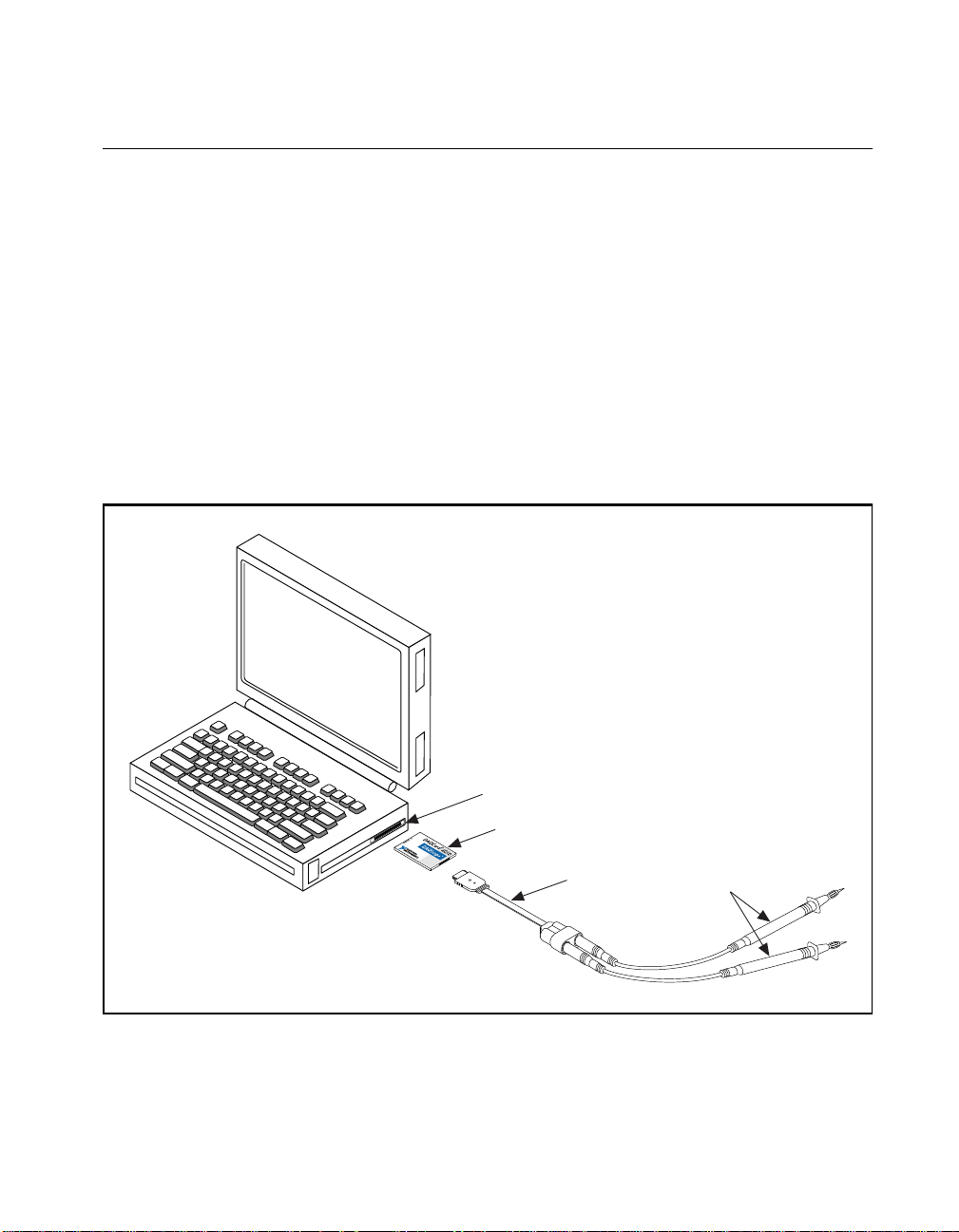
2. Insert the DAQCard-4050 and attach the DAQCard-4050 accessory
cable.
The DAQCard-4050 ha s two co nnec tors—a 6 8-pin PC MCI A bus
connector on one e nd and a 4- pin I/O c on nector on the other en d.
Insert the PCMCIA bus connector into any available Type II
PCMCIA slot until the connector is seated firmly. Notice that the
DAQCard-4050 and th e DAQCar d-4050 accessory cable are bo th
keyed so that the cable ca n b e inse rted o nly one wa y.
Be careful not to put strain on the DAQCard-4050 accessory cable
when inserting it into and removing it from the DAQCard-4050.
Always grasp the cable by the connec tor you are pluggin g or
unplugging. Never pull directly on the DAQCard-4050 accessory
cable to unplug it from the DAQCard-4050.
The DAQCard-4050 is n ow insta lled.
DAQMeter DAQCard-4050 User Manual 2-2
©
National Instruments Corporation
Page 17
Cable and Probes
The DAQCard-4050 kit contains the DAQCard-4050 accessory cable,
which connects the DAQCard-4050 to a pair of test probes with
shrouded banana plugs. These probes are also included in the kit. Bo th
the DAQCard-4050 accessory cable and the test probes meet
international safety requirements including U L 3111 and IEC 1010-1
for the full ranges of applications supp orted by the DAQC ard-4 050.
Before using any probe s or acc essorie s no t supplied by Na tiona l
Instruments, ensure that they meet applicable safety requirements for
the signal levels you may en co unter.
To use the DAQCard-4050 acce ssory cable an d probe s with the
DAQCard-4050, first connect the cable to the card as shown in
Figure 2-1. The accessory cable connector is p olari zed so that it cann ot
be plugged in incorrectly.
Chapter 2 Installation and Configuration
Portable
Computer
PCMCIA Slot
DAQCard-4050
Accessory Cable
Figure 2-1.
©
National Instruments Corporation 2-3 DAQMeter DAQCard-4050 User Manual
Installing the DAQCard-4050 and Cables
Probes
Page 18
Chapter 2 Installation and Configuration
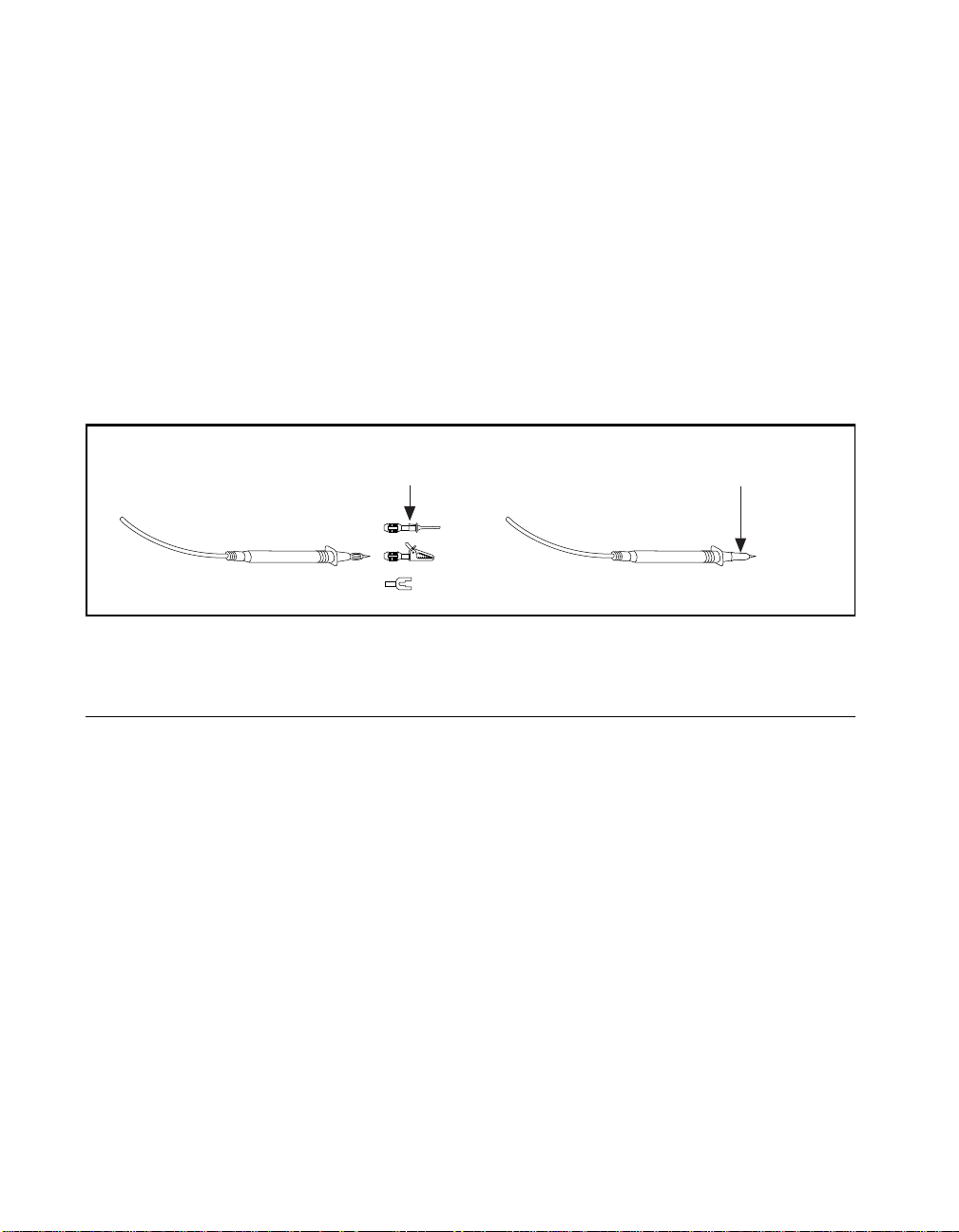
The test probes connect to the DAQCard-4050 accessory cable via
shrouded banana jack s. Th e shrouds a round the bana na ja cks p re vent
you from contacting poten tially h azardo us voltages c onnec ted to the
test probes. You can also connec t the cable to standard (un shroude d)
banana jack probes or accessories; however, use unshrouded probes or
accessories only when the vo ltages are less than 30 V
You can use the measurement ends of the test probes in either of two
ways, as shown in Figure 2-2. With the plastic covers over the ends, you
can use the probes to directly probe the circuit or device to be tested.
With the plastic tip covers removed, the test probes can accept standard
banana jack accessories (such as spade lugs, alligator clips, or spring
clips), which are available from National Instruments.
or 42 V
rms
pk-to-pk
.
Standard Banana
Jack Accessories
Hardware Configuration
The DAQCard-4050 is a fully softw are -conf igur able, Plug an d Play
device. Configuration information is stored in nonvolatile memory. The
Plug and Play services que ry the d evi ce, rea d the in forma tion, a nd
arbitrate resource a llocation for it ems such as base address a nd interrupt
level. After assigning these resources, the operating system enables the
device for operation.
Plastic Tip Cover
(Included with Probe Kit)
OR
Figure 2-2. Probe Types
DAQMeter DAQCard-4050 User Manual 2-4
©
National Instruments Corporation
Page 19

Chapter
DMM Operation
This chapter describes ho w to use your DAQMet er DAQCard-4050 an d
includes operation tips on taking voltage, resistance, diode, and current
readings.
Warm-up
Measurements taken wit h the DAQCard-4050 chan ge with temperature.
These changes are called thermal drifts or temperature coeffi cients. The
DAQCard-4050 temperature coefficient specifications are listed in the
Accuracy sections in Appendix A, Specifications. PCMCIA sl o ts,
especially those in m any n ote book c om puters, ca n wa rm up a ca rd
significantly above the ambient temperature. Therefore, measurements
made immediately after inserting the DAQCard-4050 or powering up
the computer can differ signif icantly from m easurements m ade after the
DAQCard-4050 has fully warmed up.
To minimize th e effe cts of thermal drif t and ens ure th e spec ified
accuracies, let the DAQ Card-4050 warm up for at least 30 seconds after
power-up before taking measure ments. To maximize the relativ e
accuracy of measurements, take all measurements after the
DAQCard-4050 has had a chance to fully warm up in the computer,
about 15 minutes.
3
Choosing a Reading Rate
In all measurement ranges and mode s of the DAQCar d-4050, th ere
are three possible reading rates available for use —10, 50, an d
60 readings/s. The reading rate is the rate at which a new m easu re me nt
is taken. In addition to the measurement speed, the selection of the
reading rate affects the filtering, and thus the noise level, of
measurements.
©
National Instruments Corporation 3-1 DAQMeter DAQCard-4050 User Manual
Page 20

Chapter 3 DMM Operation
In NI-DAQ, you set the reading rate directly. To optimize the
measurement accuracy and minimize the noise level, you should choose
a reading rate of 10 r eading s/s . I f you a re u s ing the D AQC ard -4050
Instrument Driver, select the resolution or the aperture time. Also
called the number of powerline cycles, aperture time is the period of
time over which a measurement is averaged. The setting of resolution
and aperture time for the DAQCard-4050 Instrument Driver are
discussed in the
diskette.
In practice, much of the noise encounter ed in measure ments occu rs
at harmonics (multiples) of the local power line frequency. The
DAQCard-4050 filters out noise at harmonics of its reading rate. A
reading rate of 50 readings/s filters noise at harmonics of 50 Hz, while
a reading rate of 60 readings/s filters noise at harmonics of 60 Hz. Since
both 50 Hz and 60 Hz are multiples of 10 Hz, choosing a sample rate of
10 reading per second will let the DAQCard-4050 filter out harmonics
of both 50 Hz and 60 Hz.
Measuring Voltages
ni_dmm.hlp file on the instrument driver installation
Connect the test probes to voltage signals as shown in Figure 3-1. For
DC voltages, the HI (red) terminal is the positive terminal, and the LO
(black) terminal is negative. For AC voltages, positive and negative
terms are irrelevant.
The DAQCard-40 50 is pro tec ted a gain st da mage from v oltages within
±250 VDC or 250 V
rms
above these levels to the inputs.
Caution: To prevent possible safety hazards, the maximum voltage between either of
!
DAQMeter DAQCard-4050 User Manual 3-2
the inputs and the ground of the computer should never exceed ±250 VDC
or 250 V
250 V
MAX.
.
rms
HI
DC Voltage
+
Source
-
LO
Figure 3-1.
Connecting Probes for Voltage Measurement
in all ranges. You should never apply voltages
HI
250 V
MAX.
LO
©
National Instruments Corporation
AC Voltage
Source
Page 21

DC Voltages
Chapter 3 DMM Operation
Input Ranges
The DAQCard-4050 ha s fi ve inpu t rang es a vailable for me as uring DC
voltages. These ranges are ±20 mV, ±200 mV, ±2.0 V, ±25 V, and
±250 V. The DAQCard-4 050 can measure DC voltages to its specified
accuracy as long as the voltage is within the selected input range. The
DAQCard-4050 can mea sure volta ges ou tsid e of the input r an ge ( the
overrange) with reduced accuracy. Table 3-1 shows the accuracy,
typical overrange, and input impeda nce of each of the input ranges.
Table 3-1.
Input
Range
±20 mV 0.005% 0.1% ±22 mV > 1 GΩ
±200 mV 0.005% 0.025% ±220 mV > 1 GΩ
±2.0 V 0.004% 0.01% ±2.2 V > 1 GΩ
±25 V 0.006% 0.035% ±27 V 1 MΩ
±250 V 0.006% 0.007% ±250 V 1 MΩ
Percent of
Reading
Error
DC Input Range Accuracy
Percent of
Range
Error
Overrange Input
Impedance
Accuracy Considerations
If you are making sensitive measurements (measurements that need a
high degree of accuracy), you should consider problems associated with
input impedance, AC noise effects, and thermal electromo tive fo rces
(thermal EMFs).
Input Impedance
The input impedance of the DAQCard -4050 can ca use additio nal span
errors by creating an attenuator with the impedance of the circuit under
test. Although the high (>1 GΩ) impedance in the low er three input
ranges is not likely to cause any significant errors, the lower impedance
of the ±25 V and ±250 V ranges can attenuate (make smaller) the signal
being measured.
©
National Instruments Corporation 3-3 DAQMeter DAQCard-4050 User Manual
Page 22

Chapter 3 DMM Operation
Figure 3-2 illustrates the input impedance of the DAQCar d-4050 and its
effect on the meas urem en t of a c ircuit u nde r test. I f the sour ce
impedance of the circuit being tested is known, you can corre ct for the
attenuation caused by the DAQCard-4050 in software.
External
DAQCard-4050
+
Source
Impedance R
R
V
in
s
s
=
V
m
Rs +R
in
Measured
Voltage
V
m
-
Input
Impedance
R
in
+
-
Source
Voltage V
s
Figure 3-2. The Effect of Input Impedance on Signal Measurement
AC Noise Effects
The DAQCard-4050 filters out AC voltages while in the DC voltage
measurement ranges. However, if the amplitude s of the AC voltages are
large compared to the DC v oltages, or if the peak value (AC+D C) of the
measured voltage is outside the overrange limits, the DAQCard-4050
may exhibit additional errors. To minimize these errors, keep the circuit
under test and the DA QCar d-4 050 a way fr om strong A C m agne tic
sources and minimize the area of the loop formed by the test leads.
Choosing the 10 readings/s reading rate will also help minimize noise
from AC sources. If the peak value of the measured voltage is likely to
exceed the selected input range, select the next high input range.
Thermal EMF
Thermal EMFs, or th ermoelectric potentials, are voltages generated at
the junctions of dissimilar metals and are functions of temperature.
Thermal EMFs in a ci rcuit und er te st can cau se high er than ex pect ed
offsets that change w ith varian ces in tempe ratur e. Oc casion ally
these voltages are desirable, such as when the thermal EMF of a
thermocouple is used to measure temperature changes. Other times
these voltages are sources of error.
DAQMeter DAQCard-4050 User Manual 3-4
©
National Instruments Corporation
Page 23

AC Voltages
Chapter 3 DMM Operation
To minimize th erma l EMFs, use c opper leads to conne ct the signal to
the DAQCard-4050. Also, try to maintain a constant temperature in the
circuits under test, perhaps by using an enclosu re to minimize air
currents.
True RMS Method
In the AC voltage ranges, th e DAQCard-4050 measures the AC- coupled
root mean square (RMS) value of a signal. The RMS value of a signal
is a fundam en tal m eas u re me nt o f th e ma gn itud e of a n AC si gn al. T he
RMS value of an AC signal can be defined mathematicall y as the squa re
root of the average o f the square of a sig nal. In practic al terms, the RMS
value of an AC signal is the DC value required to produce an equivalent
amount of heat in the same load.
The DAQCard-4050 first AC -couples the measured signal to remove
any DC components an d th en me as ures the RMS v alu e of the AC
component. This method lets you measure a small AC signal in the
presence of a large DC offset.
Input Ranges
The DAQCard-4050 ha s fi ve inpu t rang es a vailable for me as uring AC
voltages. These ranges are 20 mV
and 250 V
. The DAQCard-4050 can measure AC voltages to its
rms
, 200 m V
rms
specified accuracy as long as the voltage is at least 10% and no more
than 100% of the selec te d inp ut ran ge. Th e DA QC ard -4050 ca n
measure voltages outside of the input range (the overra nge) with
reduced accuracy. Table 3-2 shows the accuracy and typical overrange
of each of the input ranges. The accuracy is based on a 1 kHz sine wave
of full-scale input ra ng e.
©
National Instruments Corporation 3-5 DAQMeter DAQCard-4050 User Manual
rms
, 2.0 V
rms
, 25 V
rms
,
Page 24

Chapter 3 DMM Operation
AC Input Range Accuracy
Percent of
Overrange
Range Error
0.3% 0.1% 22 mV
0.3% 0.1% 220 mV
0.4% 0.2% 2.2 V
0.4% 0.2% 27 V
0.3% 0.1% 250 V
rms
rms
rms
rms
rms
Input
Range
20 mV
200 mV
2.0 V
25 V
250 V
Table 3-2.
Percent of
Reading Error
rms
rms
rms
rms
rms
The impedance in each of these ranges is 1 MΩ. The DC component in
any of these ranges can be as high as 250 VDC .
Accuracy Considerations
The AC voltage me asu reme nt ac cu racy is depe nde nt on ma ny fa cto rs,
including the signal amplitude, frequency, and waveform shape
(or crest factor). Each of these factors, and their effects on your
measurements, are discussed below. In addition to these factors,
consider the effects of the source impeda nce of your cir cuit. These
effects are de sc ribe d in th e Input Impedance section earlier in this
chapter.
Frequency Response
The accuracy of the DAQCard-4050’s AC voltage measurements is a
function of th e in put sig nal’ s fre quen cy. Tabl e 3-3 shows the addit iona l
measurement errors associated with different frequency ranges. These
errors are for full-sc ale, sine wa ve inpu ts.
DAQMeter DAQCard-4050 User Manual 3-6
©
National Instruments Corporation
Page 25

Chapter 3 DMM Operation
Table 3-3.
Input
Frequency
Input Frequency Error Rate
Additional Error
(Percent of Full Scale)
20–50 Hz 2%
50–100 Hz 1%
100 Hz–5 kHz 0%
5–10 kHz 1%
10–25 kHz 2%
Crest Factor
The DAQCard-4050 is calibrated to optimize the accuracy of measuring
sine wave inputs. Because the DAQCard-4050 uses the RMS method of
the AC measurements, it can also accurately measure inputs other than
sine waves. The ac cu ra cy o f th es e m eas u rem en ts d ep en d s on th e crest
factor of the input signal. The crest factor of a signal is the ratio of the
peak value of the signal to the RMS valu e of the sig n al. For ex amp le , a
symmetrical square wave has a crest factor of 1 and an undistorted sine
wave has a crest factor of 1.4. The DAQCard-4050 can measure signals
with crest factors of up to 10.
Table 3-4 shows the additional errors associated with different crest
factors.
Table 3-4.
Crest
Factor
Crest Factor Error Rate
Additional Error
(Percent of Full Scale)
1–2 no error
2–5 1%
5–10 2%
©
National Instruments Corporation 3-7 DAQMeter DAQCard-4050 User Manual
Page 26

Chapter 3 DMM Operation
AC Voltage Offset
The AC measurements of the DAQCard-4050 are specified over the
range of 10% to 100% of the full scale input range. Below 10% of the
input range, errors due to the AC vo ltage o ffset b ecom e signifi cant.
This offset, unlike DC voltage offsets, cann ot simply be subtracted from
the readings or ze roed out because the o ffset ge ts conver ted in the R MS
conversion. The relations hip between the input volta ge, AC offse t
voltage, and the measured voltage is as follows:
2
Vmeasured Vin
()
()
Voffset
+=
For example:
Range = 200 mV
rms
Input voltage = 100 mV
AC offset voltage = 0.5 mV
The measured voltage in this example wo uld be
V
measured
0.001 mV
= 10 0.001 mV
of error and is, there fore, negligible. However, if the input
rms
voltage were only 10 mV
10.012 mV
. To minimize the error s due to the A C offs et voltag e,
rms
; the 0.5 mV
rms
, the measured voltage wou ld b e
rms
choose an input range that keeps the measured volta ge between 10%
and 100% of full scale.
rms
2
rms
offset contributes on ly
rms
Measuring Resistance
Signal Connections
Connect the test probes to resistors as shown in Figure 3-3. To
accurately measure the value of a resistor, make sure the resistor is not
connected to any other circuits. Erroneou s or misleading readings may
result if the resistor you are measuring is connected to external circuits
that supply voltages or currents or to external circuits that change the
effective resistance of that resistor.
Figure 3-3.
DAQMeter DAQCard-4050 User Manual 3-8
HI
250 V
MAX.
LO
Connections for Resistance Measurement
Resistor
©
National Instruments Corporation
Page 27

Caution: To prevent possible safety hazards, the maximum voltage between either of
!
Input Ranges
Chapter 3 DMM Operation
The DAQCard-4050 is protected against damage from voltages within
±250 VDC or 250 V
in all ranges. However, voltages above these
rms
levels should never be a pp lied to th e inputs.
the inputs and the ground of the computer should never exceed ±250 VDC
or 250 V
rms
.
The DAQCard-4050 has five basic input ranges for resistance as well as
an extended range. The basic ranges are 200 Ω, 2.0 kΩ, 20 kΩ, 200 kΩ,
and 2 MΩ. With the extended range, measurements up to at least
20 M Ω ar e poss ible.
The DAQCard-4050 me asure s resistance by sen ding a curr ent through
the test resistor and measuring the voltage this current develops across
the resistor. In the E xten ded O hm s range , the DA QCar d-4 050 a dds a
1MΩ resistor in parallel with the test resistor, and then calculates the
value of the resisto r bein g tested . Ta ble 3- 5 shows the acc urac y of the
readings in the di ffer ent ra nges.
Table 3-5.
Input
Range
Resistance Input Range Accuracy
Excitation
Current
Percent of
Reading Error
Percent of
Range Error
200 Ω 100 µA 0.007% 0.2%
2.0 kΩ 100 µA 0.007% 0.03%
20 kΩ 100 µA 0.007% 0.02%
200 kΩ 1 µA 0.01% 0.03%
2 MΩ 1 µA 0.01% 0.06%
Extended Ohms 1 µA See note below.
Note: The accuracy of measurements made in the Extended Ohms range
varies with the value being measured. For resistances up to 1 MΩ, the
accuracy is 0.05%. For resistances between 1 MΩ and 20 MΩ, the
accuracy is 0.1%. For larger resistances, the error is 0.4%.
©
National Instruments Corporation 3-9 DAQMeter DAQCard-4050 User Manual
Page 28

Chapter 3 DMM Operation
Continuity Measurements
Many traditional multimeters can make continuity measurements,
which test for the presence or absence of continuity between the two test
probes. These measurements are simply resistance measurements,
where the resistanc e betwee n the two probes is measure d and co mpared
to a set value. You can perform continuity measurements on a circuit by
setting the DAQCard-4050 to the 200 Ω range and comparing the
measured valu e to some low re sist ance valu e (10 Ω is typical). If the
measured value is less than 10 Ω, there is continuity between the test
probes.
Testing Diodes
You can also use the DAQCard-4 050 to measure the forward drop
across a diode. You can measure voltage drops of up to 2 V.
Signal Connections
Connect the test probes to a diode as shown in Figure 3-4. To accurately
measure the forwar d v olt ag e of a dio d e, mak e su re that the diode is not
connected to any other circuits. The DAQCard-4050 biases the diode
with a current of 100 µA and measures the resulting voltage drop. Diode
measurements are made with a fixed range of 2.0 V and an accuracy of
0.01%.
Figure 3-4.
DAQMeter DAQCard-4050 User Manual 3-10
HI
250 V
MAX.
LO
Connections for Diode Measurement
100 µA
+
Diode
-
©
National Instruments Corporation
Page 29

Measuring Current
You can use the DAQCard-4050 to measure curr ent with an optional
National Instruments CSM series current shunt module. These
accessories are connected between the DAQCard-4050 cable and the
test probes as shown in Figure 3-5.
250 V
MAX.
HI
LO
Chapter 3 DMM Operation
Current
Source
Current Shunt
Accessory
Figure 3-5.
Connections for Current Measurement
Current shunt accessories contain a precision resistor that converts the
current through the shunt into a voltage that the DAQCard-4050 can
measure in voltage mode. You can calculate the value of the current
flowing through the shunt by dividing the voltage reading by the value
of the precision resistor.
©
National Instruments Corporation 3-11 DAQMeter DAQCard-4050 User Manual
Page 30

Appendix
Specifications
This appendix lists the specifications of the DAQMeter
DAQCard-4050. These specifications are typical at 25° C unless
otherwise specified. The ope rating tem pera ture ran ge is 0° to 55 ° C.
DC Voltage
Accuracy
250.000 V 0.006% + 0.007% 9 ppm + 5 ppm 250.000 V
25.0000 V 0.006% + 0.035% 9 ppm + 30 ppm 27.0000 V
2.00000 V 0.004% + 0.01% 5 ppm + 5 ppm 2. 200 00 V
200.000 mV 0.005% + 0.025% 5 ppm + 20 ppm 220.000 mV
Range Accuracy*
±(% of reading +
%of range)
Temperature
Coefficient
±(ppm of reading +
ppm of range)/°C
A
Overrange
20.000 mV 0.005% + 0.1% 5 ppm + 175 ppm 22.0000 mV
* Percent of range incl udes the effects of nonl inearity, noise, and offset errors.
Noise Rejection
NMRR (10 Hz filter se tting, 50/60 H z
power line fr eq uen cy ± 5% ) ...... .. .. .... .. . 80 dB
DC CMRR ............ .. .... .. .. ..... .. .. .... .. .... .>130 dB
AC CMRR ............ .. .... .. .. ..... .. .. .... .. .... .90 dB, 60 Hz
Input Characteristics
Input bias cu rre nt .. .. .... .. .. ..... .. .. .... .. .... .100 pA, 1 nA ma x
©
National Instruments Corporation A-1 DAQMeter DAQCard-4050 User Manual
Page 31

Appendix A Specifications
Input resista nc e .. .. .. .... .. .. .. ..... .. .. .. .... .. . >1 GΩ (2 V, 20 0 mV,
20 mV ranges ); 1 M Ω (250 V,
25 V ranges)
Linearity .. ...... .... .... .... .... .... ....... .... .... . 0.001 5%
AC Voltage
Accuracy
Range Accuracy
±(% of reading +
% of range)
250.000 V 0.3% + 0.1% 60 ppm + 10 ppm 250.000 V
25.0000 V 0.4% + 0.2% 60 ppm + 80 ppm 27.0000 V
2.00000 V 0.4% + 0.2% 60 ppm + 100 ppm 2.20000 V
200.000 mV 0.3% + 0.1% 60 ppm + 50 ppm 220.000 mV
20.0000 mV 0.3% + 0.1% 60 ppm + 50 ppm 22.0000 mV
Temperature
Coefficient
±(ppm of re ad ing
+ ppm of
range)/°C
Overrange
Additional AC Errors
Frequency dependent error s
Input Frequency Additional Error
20–50 Hz 2%
50–100 Hz 1%
(% of full scale)
DAQMeter DAQCard-4050 User Manual A-2
100 Hz–5 kHz 0%
5–10 kHz 1%
10–25 kHz 2%
©
National Instruments Corporation
Page 32

Appendix A Specifications
Crest factor errors
Crest Factor Additional Error
1–2 no error
2–5 1%
5–10 2%
Noise Rejection
AC CMRR ............ .. .... .. .. ..... .. .. .... .. .... .>90 dB, 60 Hz
Input Characteristics
Bandwidth ...... .... ...... .... ..... ...... .... ...... . 20 Hz–25 kH z
Input resista nc e..... .. .. .... .. ... .. .... .. .. .. .... .1 MΩ
Resistance
Accuracy
(% of full scale)
Range Accuracy
200.000
2.00000 k
20.0000 k
200.000 k
2.00000 M
Extended
Ohms
*The accurac y of mea sur emen ts made i n th e Ex te nded Ohms ran ge v arie s wi th th e val ue b e ing
measured. For resistances up to 1 MΩ, the accuracy is 0.05%. For resista nce s bet w e en 1 MΩ
and 20 MΩ, the accuracy is 0.1%. For larger resistances, the error is 0.4%.
©
National Instruments Corporation A-3 DAQMeter DAQCard-4050 User Manual
±(% of reading +
% of range)
Ω
0.007% + 0.2% 13 ppm + 175 ppm 200.000
Ω
0.007% + 0.03% 13 ppm + 20 ppm 2.00000 k
Ω
0.007% + 0.02% 13 ppm + 3 ppm 20.0000 k
Ω
0.01% + 0.03% 17 ppm + 20 ppm 200.000 k
Ω
0.01% + 0.06% 17 ppm + 3 ppm 2.00000 MΩ1 µA
0.05% + 0.006 %* 500 ppm + 30 ppm n/a 1 µA
Temperature
Coefficient
±(ppm of reading +
ppm of range)/°C
Overrange Test
Current
Ω
100 µA
Ω
100 µA
Ω
100 µA
Ω
1 µA
Page 33

Appendix A Specifications
Diode
Accuracy
Range Accurac y
±(% of reading +
% of range)
2 V 0.01 % + 0.01% 10 ppm + 10 ppm 2.2 V 100 µA
Temperature
Coefficient
±(ppm of reading
+ ppm of range)
Overrange Test
Current
General Specifications
Settling time .......................................Determined by source
impedance, user cable
construction, and input signal
changes
Warm-up time.................................... 30 seconds before making
measurements; 15 minutes for
measurements accurate within
typical specifications
Bus interface ty pe .... .... .... ..... ...... .... ... Slav e
Safety .....................................................Designed in accordance with
IEC 1010-1 and UL 3111 for
measuring and testing eq uipment;
Installation Category II
Pollution Degree 2
Double Insulated
Indoor use
Altitude .. .... .. .. .. .... .. .. .. .... .. .. ... .... .. .. .. ... For use u p to 2 ,00 0 m
Maximum working voltage
between either input terminal
and earth ground .. .. .. .... .. .. ..... .. .. .... .. ... 250 V m a x
Powe r requ i r emen t ................................+5 VDC
DAQMeter DAQCard-4050 User Manual A-4
45 mA in operational mode
15 mA in power- down mode
©
National Instruments Corporation
Page 34

Appendix A Specifications
Physical
PCMCIA card t ype ... .. .... ... .. .. .... .. .. .. ...Type II
I/O connect or ............ .. .. ..... .. .. .. .... .. .. .. . 4-p i n m a le
Environment
Operating t emp er at ur e .... ..... .. .. .. .... .. .. .0° to 55° C
Storage temper at ur e ........... .... .. .. .... .. ...-55° to 15 0° C
Relative humi dity .............. .. .... .. .. .... .. . 5% to 9 0% n onc on dens ing
©
National Instruments Corporation A-5 DAQMeter DAQCard-4050 User Manual
Page 35

PC Card Questions
Appendix
and Answers
This appendix co ntains a li st of common qu estions and an swers relating
to PC Card (PCMCIA) operation. The questions are grouped according
to the type of informa tio n re quested . Yo u may f ind this inf orma tion
useful if you are having difficulty with the PCMCIA system software
configuration and y ou ar e using W in dows 3. 1.
Note:
Configuration
If you are using Windows 95, the operation system will automatically
configure your PC Card. All questions in this appendix are specific to
Windows 3.1, with the exce ption o f questi on 1 in the
1. What operating system should I use with my PC Cards?
2. Do I nee d to use my PCMCIA configuration utility to configure
B
Configuration
The PC Card should wor k with Windo ws 3.x, Windows 95 , a nd
Windows NT. We strongly recommen d that you use Windo ws 95.
the National Instruments PC Cards?
section.
No. We recommend that yo u do not conf igur e our PC C ar ds usin g
PC Card Control or an equivalent PC Card configuration utility.
Use the configuration utilities included with the NI-DAQ driver
software to properly configure your DAQCard. The appropriate
utility is the NI-DAQ Configuration Utility for Windows 3.1 users.
3. What should I do if my computer does not have Card and
Socket Services version 2.0 or later?
Contact the manufa ct urer of yo ur co mputer o r o f your PC MC IA
adapter and reque st th e late st Card a nd Soc ket Servic es PCM CI A
driver. Our NI-DAQ software will work with any Card and Socket
Service driver that is compliant to version 2.0 or higher.
©
National Instruments Corporation B-1 DAQMeter DAQCard-4050 User Manual
Page 36

Appendix B PC Card Questions and Answers
Operation
1. My PC Card works when inserted before power-on time, but it
does not work when hot inserted. What is wrong?
You may have an interrupt conflict. If you have a utility such as
MSD.EXE, run it to determine the allocated interrupts, then refer to
question 4 in the Resources section.
with Microsoft Windows.
2. My computer locks up when I use a PC Card. What should I
do?
This usually happens because Card Services allocated an unusable
interrupt level to the PC Card. For example, on some computers,
interrupt level 11 is not routed to PC Cards. If Card Services is not
aware of this, it may assign interrupt 11 to a PC Card eve n thoug h
the interrupt is not usable. When a call uses the interrupt, the
interrupt never occurs, and the c ompute r locks u p w aiting f or a
response. For information about how to locate an interru pt that is
free to be u sed , re fe r to q u es tio n 4 i n t he Resources section.
MSD.EXE is usually shipped
Resources
1. How do I determine if I have a memory conflict?
If no PC Cards are working at all, it is probably because a memory
window is not usable. Card Services uses a 4 KB memory win dow
for its own internal use . If the m emor y ca nno t be u sed , then Ca rd
Services cannot read the Card Information Structure (CIS) from the
DAQCard EPROM, which means it cannot identify cards.
There are two different me thods you can use whe n Card Servic es
has a problem reading the CIS. First, you can determine which
memory window Card Se rvices is us ing, a nd exclud e tha t wind ow
from use by Card Services and/or the memory manager. Second,
you can attempt to determine all of the memory that Card Services
can possibly use and exclude all but that memory from use by Card
Services.
DAQMeter DAQCard-4050 User Manual B-2
©
National Instruments Corporation
Page 37

Appendix B PC Card Questions and Answers
2. How do I determine all of the memory that Card Services can
use?
One way to find out w hich m emor y addre sses Ca rd Se rvice s ca n
use is to run a utility such as
MSD.EXE that scans the system and
tells you how the system memory is being used. For example, if you
run such a memory utility and it tells you that physical addresses
C0000 to C9FFF are being used for ROM access, then you kno w
that C8000–D3FFF is an invalid range for Card Services and should
be changed to CA000–D5FFF.
3. How can I find usable I/O addresses?
Identify usable I/O addresses by trial and error. Of the three
resources used—memory, I/O, interrupts—I/O conflicts will be
low. You can use the NI-DAQ Configuration Utility in Windows to
diagnose I/O space conflic ts. When you have co nfigured th e
NI-DAQ Configuration Utility for a particular I/O space, save the
configuration. If there is a conflict, the configuration utility will
attempt to report an error describing the conflict.
4. How do I find usable interrupt levels?
Some utilities, such as
MSD.EXE, will scan the system and display
information about what is us ing h ar dwa re inte rrupts. If you ha ve
such a utility, you can run it to determine what interrupts Card
Services can use. Card Services needs an interrupt for itself as
well as one interrupt for each PCMCIA socket in the system. For
example, in a system with two PCMCIA sockets, at least three
interrupts should be alloca ted f or use b y Car d Service s.
Keep in mind that utilities such as
MSD.EXE will sometimes report
that an interrupt is in use when it really is not. For example, if the
computer has one seria l por t, C OM1, a nd one p aralle l po rt, LPT 1,
you know that IRQs 4 an d 7 ar e pro ba bly in use . In g en eral, IRQ 5
is used for LPT2, bu t if th e comp uter d oes not have two pa rallel
ports, IRQ5 sho u ld b e usa ble . IRQ3 i s u sed f or CO M2 , but if t h e
computer has only has o ne seria l po rt, IRQ3 sho uld be us able .
©
National Instruments Corporation B-3 DAQMeter DAQCard-4050 User Manual
Page 38

Appendix B PC Card Questions and Answers
5. I run a memory utility, and it appears there is no memory
available for Card Services. What should I do?
You should remove your m emor y ma nager by c omme nting it o ut
of the
Memory managers often consume an enormous amount of memory,
and you will need to de termine wha t m emor y is really usa ble b y
Card Services. Whe n you ha ve de termin ed wha t m em ory is
available for Card Services, reinstall your memo ry manage r and
make the necessary change s to provide Card Service s with the
memory needed. We suggest that you use the minimum amount of
memory for Car d Se rv ices , na me ly 4 to 12 K B, w hic h free s m ore
memory for the memory ma nager.
Resource Conflicts
1. How do I resolve conflicts between my memory manager and
Card Servic es ?
Card Services can usually use memory space that is not being used
for real RAM on the system. Even when t his is the case, yo u should
still exclude the memo ry addre sses used by Car d Services from use
by any memory manager that ma y be installed.
CONFIG.SYS file. Next, you can rerun the memory utility.
DAQMeter DAQCard-4050 User Manual B-4
©
National Instruments Corporation
Page 39

Appendix
Customer Communication
For your convenience, this appendix contains forms to help you gather the information necessary to
help us solve your technical problems and a form you can use to comment on the product
documentation. When you contact us, we need th e information on the Technical Suppor t Form and the
configuration form, if your manual contains one, about your system configuration to answer your
questions as quickly as possible.
National Instruments has techn ica l assistan ce thr ou gh electronic , fa x, a nd telepho ne sys tems to
quickly provid e the informat ion you need. Our electron ic services incl ude a bullet in board ser vice,
an FTP site, a Fax-on-Demand system, and e- mail support. If you have a hardw are or softwa re
problem, first try the electronic support systems. If the information available on these systems
does not answer your questions, we offer fax and telephone support through our technical support
centers, which are staffed by applica tions engine ers.
C
Electronic Services
Bulletin Board Support
National Instruments has BBS and FTP sites dedicated for 24-hour support with a collection of files
and documents to answer most common customer questions. From these sites, you can also download
the latest instrument drivers, updates, and example programs. For recorded instructions on how to use
the bulletin board and FTP services and for BBS automated information, call (512) 795-6990. You can
access these services at:
United States: (512) 794-5422
Up to 14,400 baud, 8 data bits, 1 stop bit, no parity
United Kingdom: 01635 551422
Up to 9,600 baud, 8 data bits, 1 stop bit, no parity
France: 01 48 65 15 59
Up to 9,600 baud, 8 data bits, 1 stop bit, no parity
FTP Support
To access our FTP site, log on to our Internet host, ftp.natinst.com, as anonymous and use
your Internet address, such as joesmith@anywhere.com, as your passwor d. The support files and
documents are located in the /support directories.
©
National Instruments Corporation C-1 DAQMeter DAQCard-4050 User Manual
Page 40

Fax-on-Demand Support
Fax-on-Demand is a 24-hour inf ormation re trieval sys tem containing a library o f documents on a wide
range of technical information. You can access Fax-on-Demand from a touch-tone telephone at
(512) 418-1111.
E-Mail Support (currently U.S. only
You can submit technical support questions to the applications enginee ring team through e-m ail at the
Internet address listed below. Remember to include your name, address, and phone number so we can
contact you with solutions and sugg estions.
support@natinst.com
)
Telephone and Fax Support
National Instruments has branch offices all over the world. Use the list below to find the technical
support number for your country. If there is no Nat ional Instruments office in your countr y, contact the
source from which you purchased your software to obtain support.
Telephone Fax
Australia 03 9879 5166 03 9879 6277
Austria 0662 45 79 90 0 0662 45 79 90 19
Belgium 02 757 00 20 02 757 03 11
Canada (Ontario) 905 785 0085 905 785 0086
Canada (Quebec) 514 694 8521 514 694 4399
Denmark 45 76 26 00 45 76 26 02
Finland 09 527 2321 09 502 2930
France 01 48 14 24 24 01 48 14 24 14
Germany 089 741 31 30 089 714 60 35
Hong Kong 2645 3186 2686 8505
Israel 03 5734815 03 5734816
Italy 02 413091 02 41309215
Japan 03 5472 2970 03 5472 2977
Korea 02 596 7456 02 596 7455
Mexico 5 520 2635 5 520 3282
Netherlands 0348 433466 0348 430673
Norway 32 84 84 00 32 84 86 00
Singapore 2265886 2265887
Spain 91 640 0085 91 640 0533
Sweden 08 730 49 70 08 730 43 70
Switzerland 056 200 51 51 056 200 51 55
Taiwan 02 377 1200 02 737 4644
U.K. 01635 523545 01635 523154
Page 41

Technical Support Form
Photocopy this form and update it each time y ou make ch anges to you r software or h ardware, and use
the completed copy of this form as a reference for your current configuration. Completing this form
accurately before contacting National Instruments for technical support helps our applications
engineers answer your questions more efficiently.
If you are using any National Instruments hardware or software products related to this problem,
include the configuration forms from their user manuals. Include additional pages if necessary.
Name __________________________________________________________________________
Company _______________________________________________________________________
Address ________________________________________________________________________
_______________________________________________________________________________
Fax (___ )___________________ Phone (___ ) ________________________________________
Computer brand ________________ Model ________________ Processor___________________
Operating system (include version number)____________________________________________
Clock speed ______MHz RAM _____MB Display adapter __________________________
Mouse ___yes ___no Other adapters installed _______________________________________
Hard disk capacity _____MB Brand _____________________________________________
Instruments used _________________________________________________________________
_______________________________________________________________________________
National Instrument s hard war e produ c t mode l__________ Revision _______________ ___ ____
Configuration _______________ __ _________________ ___ ___ _________________ ___ ___ ____
National Instrument s sof t war e produ ct____________________________ Version ____________
Configuration _______________ __ _________________ ___ ___ _________________ ___ ___ ____
The problem is: __________________________________________________________________
_______________________________________________________________________________
_______________________________________________________________________________
_______________________________________________________________________________
_______________________________________________________________________________
List any error messages: ___________________________________________________________
_______________________________________________________________________________
_______________________________________________________________________________
The following steps reproduce the problem:____________________________________________
_______________________________________________________________________________
_______________________________________________________________________________
_______________________________________________________________________________
_______________________________________________________________________________
_______________________________________________________________________________
Page 42

DAQMeter DAQCard-4050 Hardware and Software
Configuration Form
Record the settings and revisions of your hardware and software on the line to the right of each item.
Complete a new copy of this form each time you revise your software or hardware configuration, and
use this form as a reference for your current configuration. Completing this form accurately before
contacting National Instruments for technical support helps our applications engineers answer your
questions more efficiently.
National Instruments Products
DAQ hardware ___________________________________________________________________
Interrupt level of hardware __________________________________________________________
DMA channels of hardware _________________________________________________________
Base I/O address of hardware ________________________________________________________
Programming choice_______________________________________________________________
NI-DAQ, LabVIEW, LabWindows/CVI, or VirtualBench version ___________________________
Other boards in system _____________________________________________________________
Base I/O address of other boards _____________________________________________________
DMA channels of other boards ______________________________________________________
Interrupt level of other boards _______________________________________________________
Other Products
Computer make and model _________________________________________________________
Microprocessor ___________________________________________________________________
Clock frequency or speed ___________________________________________________________
Type of video board installed ________________________________________________________
Operating system version ___________________________________________________________
Operating system mode ____________________________________________________________
Programming language ____________________________________________________________
Programming language version ______________________________________________________
Other boards in system _____________________________________________________________
Base I/O address of other boards _____________________________________________________
DMA channels of other boards ______________________________________________________
Interrupt level of other boards _______________________________________________________
Page 43

Documentation Comment Form
National Instruments encourages you to comment on the documentation supplied with our products.
This information helps us provide quality products to meet your needs.
Title:
Edition Date:
Part Number:
Please comment on the completeness, clarity, and organization of the manual.
_______________________________________________________________________________
_______________________________________________________________________________
_______________________________________________________________________________
_______________________________________________________________________________
_______________________________________________________________________________
_______________________________________________________________________________
_______________________________________________________________________________
If you find errors in the manual, please record the page numbers and describe the errors.
_______________________________________________________________________________
_______________________________________________________________________________
_______________________________________________________________________________
_______________________________________________________________________________
_______________________________________________________________________________
_______________________________________________________________________________
_______________________________________________________________________________
DAQMeter DAQCard -4050 U ser Manual
February 1997
321427A-01
Thank you for your help.
Name _________________________________________________________________________
Title __________________________________________________________________________
Company _______________________________________________________________________
Address ________________________________________________________________________
_______________________________________________________________________________
Phone (___ )__________________________ Fax (___ ) _________________________________
Mail to:
Technical Publications
National Instruments Corporation National Instruments Corporation
6504 Bridge Point Parkway (512) 794-5678
Austin, TX 78730-5039
Fax to:
Technical Publications
Page 44

Prefix Meaning Value
Glossary
p- pico- 10
n- nano- 10
µ- micro- 10
m- milli- 10
k- kilo- 10
M- mega- 10
G- giga- 10
-12
-9
-6
-3
3
6
9
Numbers/Symbols
% percent
+ positive of, or plus
- negative of, or minus
/per
°degree
±plus or minus
Ωohm
©
National Instruments Corporation G-1 DAQMeter DAQCard-4050 User Manual
Page 45

Glossary
A
A amperes
AC alternating current
AC coupled the passing of a sig nal thro ugh a f ilter ne twork that remo ve s the D C
component of the signal
A/D analog-to-digital
ADC analog-to-digital converter—an electronic device, often an integrated
circuit, that converts an analog voltage to a digital number
ADC resolution the resolution of the ADC, which is measured in bits. An ADC with
16 bits has a high er resolution, and thus a higher deg ree of accur acy,
than a 12-bit ADC.
amplification a type of signal conditioning that improves accuracy in the resulting
digitized signal and reduces noise
amplitude flatness a measure of how close to co nsta nt the gain of a circu it rema ins over a
range of frequencies
aperture tim e the period of tim e ove r w hi ch a m e asu r eme nt is av erag ed ; a lso c a lle d
the number of powerli ne cy cles
attenuate
to reduce in magnitude
B
b bit—one binary digit, either 0 or 1
B byte—eight related bits of data, an eight- bit binary n umb er. Also used
to denote the amount of memory required to store one byte of data.
bus the group of conductors tha t interc onn ect ind ividua l ci rcuitry in a
computer. Typ ica l ly, a bu s is th e ex pa nsi on vehi c le to w hi ch I/ O o r
other devices are conn ected. Ex amples o f PC buses are th e PCI bus, AT
bus, and EISA bus.
DAQMeter DAQCard-4050 User Manual G-2
©
National Instruments Corporation
Page 46

Glossary
C
CCelsius
CMRR common-mode rejection ratio—a measure of an instrument’s ability to
reject interference from a co mmo n- mode signal, usua lly exp resse d in
decibels (dB)
continuity the measure of the ability of a material to conduct electricity
conversion device device that transforms a signal from one form to another. For example,
analog-to-digital converters (ADCs) for analog input, digital-to-analog
converters (DACs) for analog ou tput, digital inpu t or ou tput ports, and
counter/timers are conversion devices.
conversion time the time required, in an analog input or output system, from the moment
a channel is interrogated (such as with a read instruction) t o the moment
that accurate data is available
coupling the manner in which a signal is connected from one location to another
CPU central processing unit
crest factor the ratio of the peak value of the signal to the R MS value of the s ignal
CSM current shunt module
D
DAQ data acquisition—(1) collecting and measuring electrical signals from
sensors, transducers, and test probes or fixtures and inputting them to a
computer for pro cessing ; (2 ) collecting a nd mea surin g the sam e kinds
of electrical signals w ith A /D and/or DI O board s p lugge d into a
computer, and possibly generating control signals with D/A and/or DIO
boards in the same computer
dB decibel—the unit for expressing a logarithmic mea sure of the ratio of
two signal levels: dB=20log10 V1/V2, for signals in volts
DC direct current
©
National Instruments Corporation G-3 DAQMeter DAQCard-4050 User Manual
Page 47

Glossary
default setting a default parameter value recorded in the driver. In many cases, the
default input of a control is a certain value (often 0) that means use the
current default setting. For example, the default input for a parameter
may be do not change current setting, and the defaul t setti ng may be no
AMUX-64T boa rds. If you do change the value of such a parameter, the
new value becomes the new setting. You can set default settings for
some parameters in the configuration utility or manually using switches
located on the device.
device a plug-in data acquisition board, card, or pad that c an c ontain mu ltiple
channels and co nversio n d ev ices. Plug- in b oar ds, PCM CI A c ards, and
devices such as the DAQPad-1200, w hich conne cts to your compute r
parallel port, are all examples of DAQ devices. SCXI modules are
distinct from devices, with the exception of the SCXI-1200, which is a
hybrid.
differential input an analog input consisting of two termina ls, both of which are isola ted
from computer g rou nd, w ho se diff eren ce is mea sure d
DMM digital multimeter
DNL differential nonlinearity—a measure in LSB of the worst-case deviation
of code widths from their ideal value of 1 LSB
double insulated a device that contains the necessary insulating structure s to provide
electric shock protection without the requiremen t of a safety ground
connection
DOS disk operating system
drivers software th at co ntr o ls a spec ific hardware device suc h as a DAQ board
or a GPIB interface board
E
EEPROM electrically erasable programmable read-only memory–ROM that can
be erased with an electrical signal and reprogrammed
EISA extended industry standard architecture
DAQMeter DAQCard-4050 User Manual G-4
©
National Instruments Corporation
Page 48

Glossary
F
filtering a type of signal conditioning that allows you to filter unwanted signals
from the signal you are trying to measure
ft feet
G
gain the factor by which a sig nal is amplified, sometimes expressed in
decibels
H
harmonics multiples of the fundamental frequency of a signal
half-power bandw idth the frequency range o ver w hich a c ircui t mainta ins a leve l of at le as t
-3 dB with respect to the m aximum level
hardware the physical components of a computer system, such as the circuit
boards, plug-in board s, cha ssis, enclosu re s, p eriphe rals, c ables, a nd so
on
hex hexadecimal
Hz hertz —per sec ond , as in c ycl es pe r seco nd or sample s p er sec ond
I
IBM International Business Machines
IC integrated circuit
ID identification
IEC International Electrotechnical Commission
IEEE Institute of Electrical and Electronics Engineers
in. inches
input bias current the curren t tha t f lows into the inpu ts of a c ircuit
©
National Instruments Corporation G-5 DAQMeter DAQCard-4050 User Manual
Page 49

Glossary
input impedance the measured resistance and capacitance between the input terminals of
a circuit
Installation Category classification system for expected transients on electrical supply
(Overvoltage Category) installations
instrument driver a set of high-level soft ware fun ctions tha t contr ols a s pecific GPIB ,
VXI, or RS-232 programmable instrument or a specifi c plug-in DAQ
board. Instrument drivers are available in several forms, ranging from a
function callable language to a virtual instrument (VI) in LabVIEW.
interrupt a computer signal indicating that the CPU should suspend its current
task to service a designated activity
interrupt level t he relative priority at which a device can interrupt
I/O input/output—the transfer of data to/from a computer system involving
communications channels, op er ator inte rf ace devic es, and /or da ta
acquisition and control interfac es
IRQ interrupt request
ISA industry standard arch itecture
isolation a type of signal conditioning in which you isolate the transducer signals
from the computer for sa fety p urp oses . Th is pr otects you and you r
computer from large voltage spikes and makes sure the measurements
from the DAQ device are not affect ed by differenc es in ground
potentials.
isolation voltage the voltage that an isolated circuit can normally withstand, usua lly
specified from input to input and/or from any input to the amplifier
output, or to the computer bus
K
k kilo—the standa rd metr ic prefix fo r 1 ,000, o r 103, used with units of
measure such as volts, hertz, and meters
10
K kilo—the prefix for 1,024, or 2
computer mem ory
DAQMeter DAQCard-4050 User Manual G-6
, used with B in quantifying data or
©
National Instruments Corporation
Page 50

L
LabVIEW laboratory virtual instru me nt eng inee ring w orkbe nch
M
mmeters
M (1) Mega, the standard metric prefix for 1 million or 10
with units of measure such as volts and hertz; (2) mega, the prefix for
1,048,576, or 2
memory
MB megabytes of me mo ry
20
, when used wi th B to quantify da ta or c om puter
N
NBS National Bureau of Standards
NI-DAQ National Instruments driver software for DAQ hardware
Glossary
6
, when used
NMRR normal mode rejection ratio—a measure of an instrument’s ability to
reject a signal applied directly to the differential inputs of the
instrument
noise an undesirable electrical signal—Noise comes from external sources
such as the AC power line, motors, generators, transformers,
fluorescent lights, soldering irons, CRT displays, computers, electrical
storms, welders, radio transmitters, and internal sources such as
semiconductors, resistors, and capacitors. Noise corrupts signals you
are trying to send or re ceive.
O
overrange a segment of the inp ut r ange of an instrum en t ou tside of the n orm al
measuring range. Measure ments can still be mad e, usually with a
degradation in specifications
©
National Instruments Corporation G-7 DAQMeter DAQCard-4050 User Manual
Page 51

Glossary
P
PC Card a credit-card-sized expansion card that fits in a PCMCIA slot often
referred to as a PCMCI A car d
PCMCIA an expansion bus ar chitecture that has found widespr ea d acceptance as
a de facto s tand ar d in n ot eb ook -si z e co mpu t er s. It o r igi na ted a s a
specification for add-on memory cards wr itten by the Personal
Computer Memory Ca rd I nter natio nal A ssoci ation.
peak value the absolute ma ximum o r minimum am plitude o f a signa l ( AC + D C)
pk-to-pk peak to peak value—the absolute maximum amplitude of a signal
subtracted from the absolute minimum value
Plug and Play devices devices that do not require dip switches or jumper s to configure
resources on the devices—also called switchless de vices
port (1) a communications conne ction on a computer or a remote controller
(2) a digital port, consisting of four or eight lines of digital input and/or
output
ppm parts per million
R
RAM random-access memory
range error an error in accuracy that is determined by the input range that is
selected. The range error is independent of the value of the signal being
measured.
reading error an error in accuracy that is determined by the input range, as well as the
value being measured.
reading rate the rate at which a new measurement is taken. In addition to the
measurement speed, the selection of the reading rate affects the
filtering, and thus the noise level, of measurements.
resolution the smallest signal increment that can be detected by a measurement
system. Resolution can be expressed in bits or in digits. The number of
bits in a system is roughly equal to 3.3 times the num ber of digits.
DAQMeter DAQCard-4050 User Manual G-8
©
National Instruments Corporation
Page 52

Glossary
rms root mean square—a measure of signal amplitude; the square root of the
average value of the square of the instantaneous signal amplitude
ROM read-only memory
S
s seconds
Ssamples
settling time the amount of time required for a voltage to reach i ts final value wit hin
specified limits
SNR signal-to-noise ratio–the ratio of the overall rms signal level to the rms
noise level, expressed in dB
S/s samples per second—used to express the rate at which a DAQ board
samples an analog signal
system noise a measure of the amount of noise seen by an a nalog circuit or an ADC
when the analog inp uts a re g rounde d
T
temperature the percentage that a measurement will vary according to temperature.
coefficient See also thermal drift.
thermal drift measurements that changes as the temperature varies
thermoelectric See thermal EMFs.
potentials
thermal EMFs thermal electromotive forces—voltages generated at the junctions of
dissimilar metals that are functions of temperature. Also called
thermoelectric potentials.
transfer rate the rate, measured in bytes/s, at which data is mo ved from source to
destination after software initialization and set up operations; the
maximum rate at wh ich the h ardwar e can op erate
©
National Instruments Corporation G-9 DAQMeter DAQCard-4050 User Manual
Page 53

Glossary
U
UL U nderwrite rs Labora tory
update the ou tput equivalent of a sc an. One or mo re analog or digita l output
samples. Typically, the number of output samples in an update is equal
to the number of ch anne ls in the ou tput gr oup . Fo r exa mp le, on e pu lse
from the update clock produces one update which sends one new sample
to every analog output c hannel in the group .
update rate the number of output u pdate s per seco nd
V
V volts
VDC volts direct curre nt
VI virtual instrument—(1) a c ombina tion o f har dware and/o r so ftware
elements, typically use d with a PC, that has the f unctionality of a cl assic
stand-alone instrum ent (2) a La bVIEW sof tware module (VI) , whi ch
consists of a front panel user interface and a block diagram program
V
rms
volts, root mean square value
W
waveform shape the shape the magnitud e of a sign al crea tes ov er time
working voltage the highest voltage that sh ould be a pplied to a p roduc t in nor mal use ,
normally well under the brea kdo wn vo ltage for sa fety m a rgin.
DAQMeter DAQCard-4050 User Manual G-10
©
National Instruments Corporation
Page 54

Index
A
AC noise effects, 3-4
AC voltage measurement, 3-5 to 3-8
AC voltage offset, 3-8
accuracy considerations, 3-6 to 3-8
connecting probes (figure), 3-2
crest factor, 3-7
frequency response, 3-6 to 3-7
input ranges, 3-5 to 3-6
true RMS method, 3-5
AC voltage specifications, A-2 to A-3
accuracy (table), A-2
crest factor errors (table), A-3
frequency dependent errors (table), A-2
input characteristics, A-3
noise rejection, A-3
accuracy considerations
AC voltage measurement, 3-6 to 3-8
AC voltage offset, 3-8
crest factor, 3-7
frequency response, 3-6 to 3-7
AC voltage specifications (table), A-2
DC voltage measurement, 3-3 to 3-4
AC noise effects, 3-4
input impedance, 3-3 to 3-4
thermal EMF, 3-4 to 3-5
DC voltage specifications (table), A-1
aperture time, 3-2
attenuation of signals, 3-3
B
bulletin board support, C-1
bus interface type, A-4
C
cables, installing, 2-3 to 2-4
configuration
PC card questions and answers, B-1
continuity measurements, 3-10
crest factor
definition, 3- 7
error rate (table), 3-7, A-3
current measurement, 3-11 to 3-12
customer communication, xi, C-1 to C-2
D
DAQMeter DAQCard-4050
features, 1-1
optional equipment, 1-5
requirements for getting started, 1-2
safety precautions, 2-1 to 2-2
software programming choices, 1-2 to 1-4
DAQMeter DAQCard-4050 Instrument
Driver and NI-DAQ, 1-3 to 1-4
National Instruments application
software, 1-2 to 1-3
VirtualBench software, 1-3
unpacking, 1-5
DAQMeter DAQCard-4050 Instrument
Driver, 1-3 to 1-4
©
National Instruments Corporation I-1 DAQMeter DAQCard-4050 User Manual
Page 55

Index
DC voltage measurement, 3-3 to 3-5
AC noise effects, 3-4
accuracy considerations, 3-3 to 3-5
connecting probes (figure), 3-2
input impedance, 3-3 to 3-4
input ranges, 3-3
thermal EMF, 3-4 to 3-5
DC voltage specifications, A-1 to A-2
accuracy (table), A-1
input characteristics, A-1 to A-2
noise rejection, A-1
digital multimeter operation. See DMM
operation.
diode testing
accuracy (table), A-4
signal connections, 3-11
DMM operation, 3-1 to 3-12
current measurement, 3-11 to 3-12
diode testing, 3-11
reading rate selection, 3-1 to 3-2
resistance measurement, 3-8 to 3-10
continuity measurements, 3-10
input ranges, 3-9 to 3-10
signal connections, 3-8 to 3-9
voltage measurement, 3-2 to 3-8
AC voltages, 3-5 to 3-8
connecting probes (figure), 3-2
DC voltages, 3-3 to 3-5
preventing safety hazards
(caution), 3-2
warm-up, 3-1
documentation
conventions used in manual, x
National Instrument s docu ment at i on, xi
organization of manual, ix-x
related documentation, xi
E
electronic support services, C-1 to C-2
e-mail support, C-2
environment specifications, A-5
equipment, optional, 1-5
errors, AC voltage
crest factor errors (table), 3-7, A-3
input frequency errors (table), 3-7, A-2
input range accuracy (table), 3-6, A-2
F
fax and telephone support numbers, C-2
Fax-on-Demand support, C-2
frequency error rates (table), 3-7, A-2
frequency r esponse, 3- 6 to 3-7
FTP support, C-1
G
general specifications, A-4
I
input characteristics
AC voltage specifications, A-2 to A-3
DC voltage specifications, A-1 to A-2
input impedance, 3-3 to 3-4
input ranges
AC voltage measurement, 3-5 to 3-8
DC voltage measurement, 3-3 to 3-5
resistance measurement, 3-8 to 3-10
installation
cables and probes, 2-3 to 2-4
configuration, 2-4
procedure, 2-2
safety precautions, 2-1 to 2-2
unpacking the DAQMeter
DAQCard-4050, 1-5
DAQMeter DAQCard-4050 User Manual I-2
©
National Instruments Corporation
Page 56

Index
L
LabVIEW application software, 1-2 to 1-3
LabWindows/CVI application software, 1- 3
M
manual. See documentation.
maximum working voltage, A-4
measurement. See DMM operation.
N
NI-DAQ driver software, 1-4
noise
AC noise effects, 3-4
setting reading rate for filtering, 3-2, 3-4
noise rejection specifications
AC voltage, A-3
DC voltage, A-1
O
operation of DAQMeter DAQCard-4050. See
DMM operation.
overrange
definition, 3-5
typical overrange of input ranges
(table), 3-6
P
PC card questions and answers, B-1 to B-4
configuration, B-1
operation, B-2
resource conflicts, B-4
resources, B-2 to B-4
physical specifications, A-5
power requirements, A-4
powerline cycles, 3-2
probes, installing, 2-3 to 2-4
Q
questions and answers. See PC card quest ions
and answers.
R
reading rate, 3-1 to 3-2
definition, 3- 1
minimizing noise, 3-2
setting, 3-2, 3-4
requirements for getting started, 1-2
resistance measurement, 3-8 to 3-10
continuity measurements, 3-10
input range accuracy (table), 3-10, A-3
input ranges, 3-9
signal connections, 3-8 to 3-9
root mean square (RMS) value of signal, 3-5
S
safety precautions, 2-1 to 2-2
safety specifications, A-4
settling time, A-4
signal connections
current measurement, 3-12
diode testing, 3-11
resistance measurement, 3-8 to 3-9
software programming choices, 1-2 to 1-4
DAQMeter DAQCard-4050 Instrument
Driver and NI-DAQ, 1-3 to 1-4
National Instruments application
software, 1-2 to 1-3
VirtualBench software, 1-3
specifications
AC voltage, A-2 to A-3
accuracy (table), A-2
crest factor errors (table), A-3
frequency dependent errors
(table), A-2
©
National Instruments Corporation I-3 DAQMeter DAQCard-4050 User Manual
Page 57

Index
input characteristics, A-3
noise rejection, A-3
DC voltage, A-1 to A-2
accuracy (table), A-1
input characteristics, A-1 to A-2
noise rejection, A-1
diode accuracy (table), A-4
environment, A-5
general specifications, A-4
physical, A-5
resistance (table), A-3
T
technical support, C-1 to C-2
telephone and fax support numbers, C-2
temperature coefficients, 3-1
testing diodes, 3-11
thermal drift, 3-1
thermal EMF, minimizing, 3-4 to 3-5
thermoelectric potentials, 3-4
true RMS method, AC voltage measurement,
3-5
connecting probes (figure), 3-2
DC voltages, 3-3 to 3-5
AC noise effects, 3-4
accuracy considerations, 3-3 to 3-5
input impedance, 3-3 to 3-4
input ranges, 3-3
thermal EMF, 3-4 to 3-5
preventing safety hazards (caution), 3-2
W
warm-up time, 3-1, A-4
U
unpacking the DAQMeter
DAQCard-4050, 1-5
V
VirtualBench software, 1-3
voltage measurement, 3-2 to 3-8
AC voltages, 3-5 to 3-8
AC voltage offset, 3-8
accuracy considerations, 3-6 to 3-8
crest factor, 3-7
frequency response, 3-6 to 3-7
input ranges, 3-5 to 3-6
true RMS method, 3-5
DAQMeter DAQCard-4050 User Manual I-4
©
National Instruments Corporation
 Loading...