

Page 1
Artisan Technology Group is your source for quality
new and certied-used/pre-owned equipment
• FAST SHIPPING AND
DELIVERY
• TENS OF THOUSANDS OF
IN-STOCK ITEMS
• EQUIPMENT DEMOS
• HUNDREDS OF
MANUFACTURERS
SUPPORTED
• LEASING/MONTHLY
RENTALS
• ITAR CERTIFIED
SECURE ASSET SOLUTIONS
SERVICE CENTER REPAIRS
Experienced engineers and technicians on staff
at our full-service, in-house repair center
Instra
Remotely inspect equipment before purchasing with
our interactive website at www.instraview.com
Contact us: (888) 88-SOURCE | sales@artisantg.com | www.artisantg.com
SM
REMOTE INSPECTION
View
WE BUY USED EQUIPMENT
Sell your excess, underutilized, and idle used equipment
We also offer credit for buy-backs and trade-ins
www.artisantg.com/WeBuyEquipment
LOOKING FOR MORE INFORMATION?
Visit us on the web at www.artisantg.com for more
information on price quotations, drivers, technical
specications, manuals, and documentation
Page 2
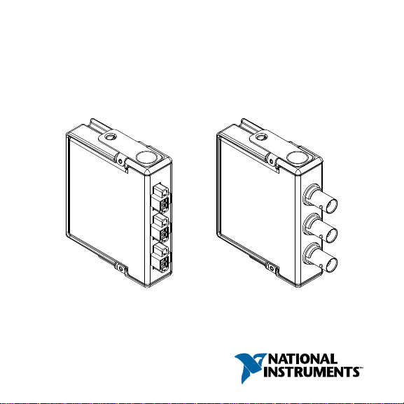
GETTING STARTED GUIDE
NI 9232
3 AI, ±30 V, 24 Bit, 102.4 kS/s/ch Simultaneous
Page 3

This document explains how to connect to the NI 9232. In this
document, the NI 9232 with screw terminal and the NI 9232 with
BNC are referred to inclusively as the NI 9232.
Note Before you begin, complete the software and
hardware installation procedures in your chassis
documentation.
Note The guidelines in this document are specific to
the NI 9232. The other components in the system might
not meet the same safety ratings. Refer to the
documentation for each component in the system to
determine the safety and EMC ratings for the entire
system.
Safety Guidelines
Operate the NI 9232 only as described in this document.
Caution Do not operate the NI 9232 in a manner not
specified in this document. Product misuse can result in
a hazard. You can compromise the safety protection
built into the product if the product is damaged in any
2 | ni.com | NI 9232 Getting Started Guide
Page 4

way. If the product is damaged, return it to NI for
repair.
Safety Voltages
Connect only voltages that are within the following limits.
Isolation
Channel-to-channel None
Channel-to-earth ground
Continuous 60 VDC, Measurement
Category I
Withstand 1,000 Vrms, verified by a 5 s
dielectric withstand test
Measurement Category I is for measurements performed on
circuits not directly connected to the electrical distribution system
referred to as MAINS voltage. MAINS is a hazardous live
electrical supply system that powers equipment. This category is
for measurements of voltages from specially protected secondary
circuits. Such voltage measurements include signal levels, special
equipment, limited-energy parts of equipment, circuits powered
by regulated low-voltage sources, and electronics.
NI 9232 Getting Started Guide | © National Instruments | 3
Page 5
Caution Do not connect the NI 9232 to signals or use
for measurements within Measurement Categories II,
III, or IV.
Note Measurement Categories CAT I and CAT O are
equivalent. These test and measurement circuits are not
intended for direct connection to the MAINS building
installations of Measurement Categories CAT II,
CAT III, or CAT IV.
Safety Guidelines for Hazardous Locations
The NI 9232 is suitable for use in Class I, Division 2, Groups A,
B, C, D, T4 hazardous locations; Class I, Zone 2, AEx nA IIC T4
and Ex nA IIC T4 hazardous locations; and nonhazardous
locations only. Follow these guidelines if you are installing the
NI 9232 in a potentially explosive environment. Not following
these guidelines may result in serious injury or death.
Caution Do not disconnect I/O-side wires or
connectors unless power has been switched off or the
area is known to be nonhazardous.
4 | ni.com | NI 9232 Getting Started Guide
Page 6
Caution Do not remove modules unless power has
been switched off or the area is known to be
nonhazardous.
Caution Substitution of components may impair
suitability for Class I, Division 2.
Caution For Division 2 and Zone 2 applications,
install the system in an enclosure rated to at least IP54
as defined by IEC/EN 60079-15.
Caution For Division 2 and Zone 2 applications,
connected low impedance sources must include a
protection device installed between the source and the
AI terminals. The protection device must prevent the
AI+ to AI- voltage from exceeding 42 V if there is a
transient overvoltage condition.
Caution For Division 2 and Zone 2 applications,
connected signals must be within the following limits.
Capacitance 0.08 μF max
NI 9232 Getting Started Guide | © National Instruments | 5
Page 7
Special Conditions for Hazardous Locations Use in
Europe and Internationally
The NI 9232 has been evaluated as Ex nA IIC T4 Gc equipment
under DEMKO Certificate No. 12 ATEX 1202658X and is
IECEx UL 14.0089X certified. Each NI 9232 is marked II 3G
and is suitable for use in Zone 2 hazardous locations, in ambient
temperatures of -40 °C ≤ Ta ≤ 70 °C. If you are using the NI 9232
in Gas Group IIC hazardous locations, you must use the device in
an NI chassis that has been evaluated as Ex nC IIC T4, Ex IIC
T4, Ex nA IIC T4, or Ex nL IIC T4 equipment.
Caution You must make sure that transient
disturbances do not exceed 140% of the rated voltage.
Caution The system shall only be used in an area of
not more than Pollution Degree 2, as defined in
IEC 60664-1.
Caution The system shall be mounted in an
ATEX/IECEx-certified enclosure with a minimum
ingress protection rating of at least IP54 as defined in
IEC/EN 60079-15.
6 | ni.com | NI 9232 Getting Started Guide
Page 8

Caution The enclosure must have a door or cover
accessible only by the use of a tool.
Electromagnetic Compatibility Guidelines
This product was tested and complies with the regulatory
requirements and limits for electromagnetic compatibility (EMC)
stated in the product specifications. These requirements and
limits provide reasonable protection against harmful interference
when the product is operated in the intended operational
electromagnetic environment.
This product is intended for use in industrial locations. However,
harmful interference may occur in some installations, when the
product is connected to a peripheral device or test object, or if the
product is used in residential or commercial areas. To minimize
interference with radio and television reception and prevent
unacceptable performance degradation, install and use this
product in strict accordance with the instructions in the product
documentation.
NI 9232 Getting Started Guide | © National Instruments | 7
Page 9

Furthermore, any changes or modifications to the product not
expressly approved by National Instruments could void your
authority to operate it under your local regulatory rules.
Caution To ensure the specified EMC performance,
operate this product only with shielded cables and
accessories. Do not use unshielded cables or
accessories unless they are installed in a shielded
enclosure with properly designed and shielded input/
output ports and connected to the product using a
shielded cable. If unshielded cables or accessories are
not properly installed and shielded, the EMC
specifications for the product are no longer guaranteed.
Caution Electrostatic Discharge (ESD) can damage
the NI 9232. To prevent damage, use industry-standard
ESD prevention measures during installation,
maintenance, and operation.
Caution To ensure the specified EMC performance
for the NI 9232 with screw terminal, you must install
clamp-on ferrite beads (part number 782802-01) in
accordance with the product installation instructions.
8 | ni.com | NI 9232 Getting Started Guide
Page 10

Refer to the NI 9232 product page on ni.com for
purchasing information about clamp-on ferrite beads.
Caution To ensure the specified EMC performance,
the length of all I/O cables must be no longer than 30 m
(100 ft).
Cable Requirements for EMC Compliance
Select and install cables for the NI 9232 in accordance with the
following requirements:
• Connect the cable shield to the chassis ground (grounding
screw of the chassis).
• For the NI 9232 with screw terminal, install a clamp-on
ferrite bead (part number 782802-01) on the input cable for
each channel that you are connecting to on the NI 9232.
• For the NI 9232 with screw terminal, clamp-on ferrite beads
must be installed on the cable as close to the module as
possible. Placing the ferrite elsewhere on the cable noticeably
impairs its effectiveness.
NI 9232 Getting Started Guide | © National Instruments | 9
Page 11

Figure 1. Cable Connections for EMC Compliance
NI 9232
with Screw Terminal
Shield
AI0+
AI0-
Shield
AI1+
AI1-
Shield
AI2+
AI2-
Ferrite
Signal
Source
Signal
Source
Signal
Source
Ferrite Ferrite
Special Conditions for Marine Applications
Some products are Lloyd’s Register (LR) Type Approved for
marine (shipboard) applications. To verify Lloyd’s Register
certification for a product, visit ni.com/certification and search
for the LR certificate, or look for the Lloyd’s Register mark on
the product.
10 | ni.com | NI 9232 Getting Started Guide
Page 12

Caution In order to meet the EMC requirements for
marine applications, install the product in a shielded
enclosure with shielded and/or filtered power and
input/output ports. In addition, take precautions when
designing, selecting, and installing measurement probes
and cables to ensure that the desired EMC performance
is attained.
Preparing the Environment
Ensure that the environment in which you are using the NI 9232
meets the following specifications.
Operating temperature
-40 °C to 70 °C
(IEC 60068-2-1, IEC 60068-2-2)
Operating humidity
(IEC 60068-2-78)
10% RH to 90% RH,
noncondensing
Pollution Degree 2
Maximum altitude 5,000 m
Indoor use only.
NI 9232 Getting Started Guide | © National Instruments | 11
Page 13

Note Refer to the device datasheet on ni.com/manuals
for complete specifications.
Connecting the NI 9232
The NI 9232 provides connections to three simultaneously
sampled analog input channels.
12 | ni.com | NI 9232 Getting Started Guide
Page 14

Figure 2. NI 9232 Pinout
AI0+
AI0–
AI1+
AI1–
AI2+
AI2–
0
1
0
1
0
1
AI0–
AI0+
AI1–
AI1+
AI2–
AI2+
Note You must use 2-wire ferrules to create a secure
connection when connecting more than one wire to a
single terminal on the NI 9232 with screw terminal.
Each channel has a terminal to which you can connect a signal
source. The AI+ terminal of the connector provides the DC
excitation, when enabled, and the positive input signal
NI 9232 Getting Started Guide | © National Instruments | 13
Page 15

connection. The AI- terminal provides the excitation return path
and the signal ground reference.
Table 1. Signal Descriptions
Signal Description
AI+ Positive analog input signal connection
AI- Negative analog input signal connection
Connecting Signal Sources
You can connect ground-referenced or floating signal sources to
the NI 9232.
If you make a ground-referenced connection between the signal
source and the NI 9232, make sure the voltage on the AI+ and the
AI- connections are in the channel-to-earth safety voltage range
to ensure proper operation of the NI 9232. Refer to the device
datasheet on ni.com/manuals for more information about
operating voltages and overvoltage protection.
14 | ni.com | NI 9232 Getting Started Guide
Page 16

Figure 3. Connecting a Grounded Signal Source
NI 9232
AI+
AI
–
+
–
Signal
Source
Common
Mode
Voltage
NI 9232
AI+
AI
–
+
–
Signal
Source
Figure 4. Connecting a Floating Signal Source
Integrated Electronic Piezoelectric (IEPE) Sensors
The NI 9232 provides an IEPE excitation current for each
channel to measure the IEPE sensors. Typical IEPE sensors have
NI 9232 Getting Started Guide | © National Instruments | 15
Page 17

a case that is electrically isolated from the IEPE electronics. As a
result, connecting the sensor to the NI 9232 results in a floating
connection even though the case of the sensor is grounded.
Wiring for High-Vibration Applications
If your application is subject to high vibration, NI recommends
that you follow these guidelines to protect connections to the
NI 9232 with screw terminal:
• Use ferrules to terminate wires to the detachable connector.
• Use the NI 9971 backshell kit.
16 | ni.com | NI 9232 Getting Started Guide
Page 18

Where to Go Next
Located at ni.com/manuals Installs with the software
CompactRIO
NI CompactDAQ
RELATED INFORMATION
NI 9232 Datasheet
NI-RIO Help
LabVIEW FPGA Help
NI 9232 Datasheet
NI-DAQmx Help
LabVIEW Help
C Series Documentation
& Resources
ni.com/info cseriesdoc
Services
ni.com/services
NI 9232 Getting Started Guide | © National Instruments | 17
Page 19

Worldwide Support and Services
The NI website is your complete resource for technical support.
At ni.com/support, you have access to everything from
troubleshooting and application development self-help resources
to email and phone assistance from NI Application Engineers.
Visit ni.com/services for NI Factory Installation Services, repairs,
extended warranty, and other services.
Visit ni.com/register to register your NI product. Product
registration facilitates technical support and ensures that you
receive important information updates from NI.
A Declaration of Conformity (DoC) is our claim of compliance
with the Council of the European Communities using the
manufacturer’s declaration of conformity. This system affords the
user protection for electromagnetic compatibility (EMC) and
product safety. You can obtain the DoC for your product by
visiting ni.com/certification. If your product supports calibration,
you can obtain the calibration certificate for your product at
ni.com/calibration.
18 | ni.com | NI 9232 Getting Started Guide
Page 20

NI corporate headquarters is located at
11500 North Mopac Expressway, Austin, Texas, 78759-3504. NI
also has offices located around the world. For telephone support
in the United States, create your service request at ni.com/support
or dial 1 866 ASK MYNI (275 6964). For telephone support
outside the United States, visit the Worldwide Offices section of
ni.com/niglobal to access the branch office websites, which
provide up-to-date contact information, support phone numbers,
email addresses, and current events.
NI 9232 Getting Started Guide | © National Instruments | 19
Page 21

Refer to the NI Trademarks and Logo Guidelines at ni.com/trademarks for information on NI
trademarks. Other product and company names mentioned herein are trademarks or trade names
of their respective companies. For patents covering NI products/technology, refer to the
appropriate location: Help»Patents in your software, the patents.txt file on your media, or the
National Instruments Patent Notice at ni.com/patents. You can find information about end-user
license agreements (EULAs) and third-party legal notices in the readme file for your NI product.
Refer to the Export Compliance Information at ni.com/legal/export-compliance for the NI
global trade compliance policy and how to obtain relevant HTS codes, ECCNs, and other import/
export data. NI MAKES NO EXPRESS OR IMPLIED WARRANTIES AS TO THE ACCURACY OF
THE INFORMATION CONTAINED HEREIN AND SHALL NOT BE LIABLE FOR ANY ERRORS.
U.S. Government Customers: The data contained in this manual was developed at private
expense and is subject to the applicable limited rights and restricted data rights as set forth in FAR
52.227-14, DFAR 252.227-7014, and DFAR 252.227-7015.
© 2015 National Instruments. All rights reserved.
373932E-01 Dec15
Page 22

Artisan Technology Group is your source for quality
new and certied-used/pre-owned equipment
• FAST SHIPPING AND
DELIVERY
• TENS OF THOUSANDS OF
IN-STOCK ITEMS
• EQUIPMENT DEMOS
• HUNDREDS OF
MANUFACTURERS
SUPPORTED
• LEASING/MONTHLY
RENTALS
• ITAR CERTIFIED
SECURE ASSET SOLUTIONS
SERVICE CENTER REPAIRS
Experienced engineers and technicians on staff
at our full-service, in-house repair center
Instra
Remotely inspect equipment before purchasing with
our interactive website at www.instraview.com
Contact us: (888) 88-SOURCE | sales@artisantg.com | www.artisantg.com
SM
REMOTE INSPECTION
View
WE BUY USED EQUIPMENT
Sell your excess, underutilized, and idle used equipment
We also offer credit for buy-backs and trade-ins
www.artisantg.com/WeBuyEquipment
LOOKING FOR MORE INFORMATION?
Visit us on the web at www.artisantg.com for more
information on price quotations, drivers, technical
specications, manuals, and documentation
 Loading...