

Page 1
GETTING STARTED GUIDE
NI 9219
100 S/s/channel, 4-Channel C Series Universal
Analog Input Module
Page 2
This document explains how to connect to the NI 9219.
Note Before you begin, complete the software and
hardware installation procedures in your chassis
documentation.
Note The guidelines in this document are specific to
the NI 9219. The other components in the system might
not meet the same safety ratings. Refer to the
documentation for each component in the system to
determine the safety and EMC ratings for the entire
system.
Safety Guidelines
Operate the NI 9219 only as described in this document.
Caution This icon denotes a caution, which advises
you to consult documentation where this symbol is
marked.
Caution Do not operate the NI 9219 in a manner not
specified in this document. Product misuse can result in
a hazard. You can compromise the safety protection
2 | ni.com | NI 9219 Getting Started Guide
Page 3

built into the product if the product is damaged in any
way. If the product is damaged, return it to NI for
repair.
Hazardous Voltage This icon denotes a warning
advising you to take precautions to avoid electrical
shock.
Safety Guidelines for Hazardous Voltages
If hazardous voltages are connected to the device, take the
following precautions. A hazardous voltage is a voltage greater
than 42.4 Vpk voltage or 60 V DC to earth ground.
Caution Ensure that hazardous voltage wiring is
performed only by qualified personnel adhering to local
electrical standards.
Caution Do not mix hazardous voltage circuits and
human-accessible circuits on the same module.
Caution Ensure that devices and circuits connected to
the module are properly insulated from human contact.
Caution When terminals are hazardous live, you must
ensure that devices and circuits connected to the
NI 9219 Getting Started Guide | © National Instruments | 3
Page 4

module are properly insulated from human contact. You
must use the NI 9972 backshell kit to ensure that the
terminals are not accessible.
Safety Voltages
Connect only voltages that are within the following limits.
Isolation
Channel-to-channel
Continuous 250 V AC, Measurement
Category II
Withstand 1,500 V AC, verified by a 5 s
dielectric withstand test
Channel-to-earth ground
Continuous 250 V AC, Measurement
Category II
Withstand 3,000 V AC, verified by a 5 s
dielectric withstand test
4 | ni.com | NI 9219 Getting Started Guide
Page 5

Zone 2 hazardous locations applications
Channel-tochannel and
channel-to-earth
ground
60 V DC, Measurement
Category I
Measurement Category I is for measurements performed on
circuits not directly connected to the electrical distribution system
referred to as MAINS voltage. MAINS is a hazardous live
electrical supply system that powers equipment. This category is
for measurements of voltages from specially protected secondary
circuits. Such voltage measurements include signal levels, special
equipment, limited-energy parts of equipment, circuits powered
by regulated low-voltage sources, and electronics.
Note Measurement Categories CAT I and CAT O are
equivalent. These test and measurement circuits are for
other circuits not intended for direct connection to the
MAINS building installations of Measurement
Categories CAT II, CAT III, or CAT IV.
Measurement Category II is for measurements performed on
circuits directly connected to the electrical distribution system.
This category refers to local-level electrical distribution, such as
NI 9219 Getting Started Guide | © National Instruments | 5
Page 6
that provided by a standard wall outlet, for example, 115 V for
U.S. or 230 V for Europe.
Caution When using the NI 9219 above 2,000 m or in
explosive atmospheres, do not connect to signals or use
for measurements within Measurement Categories II,
III, or IV.
Caution Do not connect the NI 9219 to signals or use
for measurements within Measurement Categories III
or IV.
Safety Guidelines for Hazardous Locations
The NI 9219 is suitable for use in Class I, Division 2, Groups A,
B, C, D, T4 hazardous locations; Class I, Zone 2, AEx nA IIC T4
Gc and Ex nA IIC T4 Gc hazardous locations; and nonhazardous
locations only. Follow these guidelines if you are installing the
NI 9219 in a potentially explosive environment. Not following
these guidelines may result in serious injury or death.
Caution Do not disconnect I/O-side wires or
connectors unless power has been switched off or the
area is known to be nonhazardous.
6 | ni.com | NI 9219 Getting Started Guide
Page 7
Caution Do not remove modules unless power has
been switched off or the area is known to be
nonhazardous.
Caution Substitution of components may impair
suitability for Class I, Division 2, or Zone 2.
Caution The system must be installed in an enclosure
certified for the intended hazardous (classified)
location, having a tool secured cover/door, where a
minimum protection of at least IP54 is provided.
Special Conditions for Hazardous Locations Use in
Europe and Internationally
The NI 9219 has been evaluated as Ex nA IIC T4 Gc equipment
under DEMKO 07 ATEX 0626664X and is IECEx UL 14.0089X
certified. Each NI 9219 is marked II 3G and is suitable for use
in Zone 2 hazardous locations, in ambient temperatures of -40 °C
≤ Ta ≤ 70 °C. If you are using the NI 9219 in Gas Group IIC
hazardous locations, you must use the device in an NI chassis that
has been evaluated as Ex nC IIC T4, Ex IIC T4, Ex nA IIC T4, or
Ex nL IIC T4 equipment.
NI 9219 Getting Started Guide | © National Instruments | 7
Page 8

Caution Transient protection shall be provided that is
set at a level not exceeding 140% of the peak rated
voltage value of 85 V at the supply terminals to the
equipment.
Caution The system shall only be used in an area of
not more than Pollution Degree 2, as defined in
IEC/EN 60664-1.
Caution The system shall be mounted in an
ATEX/IECEx-certified enclosure with a minimum
ingress protection rating of at least IP54 as defined in
IEC/EN 60079-15.
Caution The enclosure must have a door or cover
accessible only by the use of a tool.
Electromagnetic Compatibility Guidelines
This product was tested and complies with the regulatory
requirements and limits for electromagnetic compatibility (EMC)
stated in the product specifications. These requirements and
limits provide reasonable protection against harmful interference
8 | ni.com | NI 9219 Getting Started Guide
Page 9

when the product is operated in the intended operational
electromagnetic environment.
This product is intended for use in industrial locations. However,
harmful interference may occur in some installations, when the
product is connected to a peripheral device or test object, or if the
product is used in residential or commercial areas. To minimize
interference with radio and television reception and prevent
unacceptable performance degradation, install and use this
product in strict accordance with the instructions in the product
documentation.
Furthermore, any changes or modifications to the product not
expressly approved by National Instruments could void your
authority to operate it under your local regulatory rules.
Caution To ensure the specified EMC performance,
operate this product only with shielded cables and
accessories.
Special Conditions for Marine Applications
Some products are Lloyd’s Register (LR) Type Approved for
marine (shipboard) applications. To verify Lloyd’s Register
certification for a product, visit ni.com/certification and search
NI 9219 Getting Started Guide | © National Instruments | 9
Page 10
for the LR certificate, or look for the Lloyd’s Register mark on
the product.
Notice In order to meet the EMC requirements for
marine applications, install the product in a shielded
enclosure with shielded and/or filtered power and
input/output ports. In addition, take precautions when
designing, selecting, and installing measurement probes
and cables to ensure that the desired EMC performance
is attained.
Preparing the Environment
Ensure that the environment in which you are using the NI 9219
meets the following specifications.
Operating temperature
(IEC 60068-2-1, IEC 60068-2-2)
-40 °C to 70 °C
Operating humidity
(IEC 60068-2-78)
10% RH to 90% RH,
noncondensing
Pollution Degree 2
Maximum altitude 2,000 m
10 | ni.com | NI 9219 Getting Started Guide
Page 11

Indoor use only.
Note Refer to the device datasheet on ni.com/manuals
for complete specifications.
NI 9219 Getting Started Guide | © National Instruments | 11
Page 12
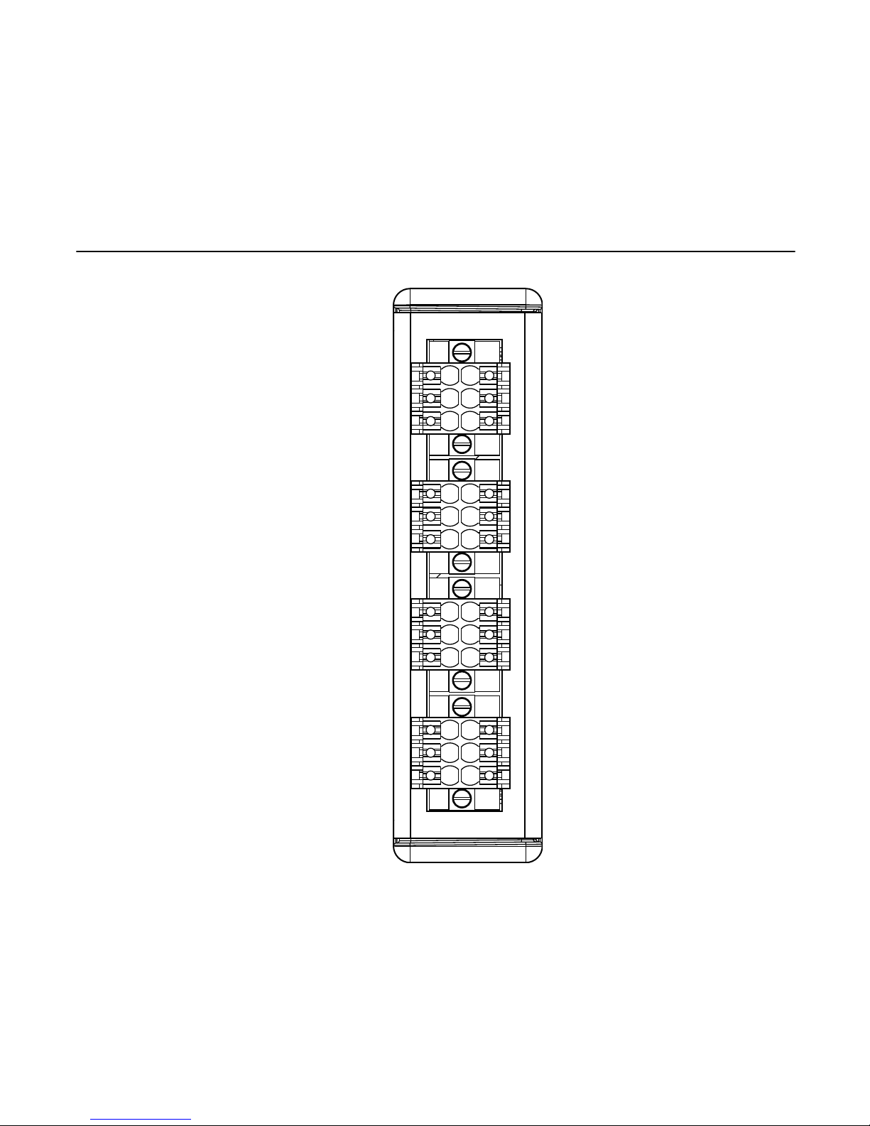
NI 9219 Pinout
1
2
3
4
5
6
1
2
3
4
5
6
1
2
3
4
5
6
1
2
3
4
5
6
CH0
CH1
CH2
CH3
12 | ni.com | NI 9219 Getting Started Guide
Page 13

Table 1. Signals by Mode
Mode Pin
1 2 3 4 5 6
Voltage T+ T- — HI LO —
Current T+ T- HI — LO —
4-Wire Resistance T+ T- EX+ HI EX- LO
2-Wire Resistance T+ T- HI — LO —
Thermocouple T+ T- — HI LO —
4-Wire RTD T+ T- EX+ HI EX- LO
3-Wire RTD T+ T- EX+ — EX- LO
Quarter-Bridge T+ T- HI — LO —
Half-Bridge T+ T- EX+ HI EX- —
Full-Bridge T+ T- EX+ HI EX- LO
NI 9219 Getting Started Guide | © National Instruments | 13
Page 14

Table 1. Signals by Mode (Continued)
Mode Pin
1 2 3 4 5 6
DI T+ T- — HI LO —
Open Contact T+ T- HI — LO —
Table 2. Signal Descriptions
Signal Description
EX+ Positive sensor excitation connection
EX- Negative sensor excitation connection
HI Positive input signal connection
LO Negative input signal connection
T+ TEDS data connection
T- TEDS COM connection
14 | ni.com | NI 9219 Getting Started Guide
Page 15

Measurement Types
The NI 9219 provides modes for the following measurement
types.
• Voltage
• Current
• 4-Wire Resistance
• 2-Wire Resistance
• Thermocouple
• 4-Wire RTD
• 3-Wire RTD
• Quarter-Bridge
• Half-Bridge
• Full-Bridge
• Digital In
1
• Open Contact
1
1
Only supported in CompactRIO systems.
NI 9219 Getting Started Guide | © National Instruments | 15
Page 16

Voltage Connections
LO
HI
NI 9219
+
–
Related Information
Voltage Pinout on page 30
16 | ni.com | NI 9219 Getting Started Guide
Page 17

Current Connections
LO
HI
NI 9219
Related Information
Current Pinout on page 30
NI 9219 Getting Started Guide | © National Instruments | 17
Page 18

Thermocouple Connections
LO
HI
NI 9219
Thermocouple
Changes in the ambient air temperature near the front connector
or a thermocouple wire conducting heat directly to terminal
junctions can cause thermal gradients. Observe the following
guidelines to minimize thermal gradients and improve the system
accuracy.
• Use small-gauge thermocouple wire. Smaller wire transfers
less heat to or from the terminal junction.
• Avoid running thermocouple wires near hot or cold objects.
• Minimize adjacent heat sources and air flow across the
terminals.
• Keep the ambient temperature as stable as possible.
18 | ni.com | NI 9219 Getting Started Guide
Page 19

• Make sure the NI 9219 terminals are facing forward or
upward.
• Keep the NI 9219 in a stable and consistent orientation.
• Allow the thermal gradients to settle after a change in system
power or in ambient temperature. A change in system power
can happen when the system powers on, the system comes
out of sleep mode, or you insert/remove modules.
Related Information
Thermocouple Pinout on page 31
NI 9219 Getting Started Guide | © National Instruments | 19
Page 20

4-Wire Resistance and 4-Wire RTD Connections
LO
HI
EX-
RTD/
Resistor
EX+
Rwire
Rwire
Rwire
Rwire
NI 9219
Related Information
4-Wire Resistance and 4-Wire RTD Pinout on page 31
20 | ni.com | NI 9219 Getting Started Guide
Page 21

3-Wire RTD Connections
RTD
Rwire
Rwire
NI 9219
EX+
EX-
LO
Rwire
Related Information
3-Wire RTD Pinout on page 32
NI 9219 Getting Started Guide | © National Instruments | 21
Page 22

Full-Bridge Connections
LO
HI
EX-
EX+
Rwire
R1 R4
R2 R3
Rwire
NI 9219
Related Information
Full-Bridge Pinout on page 32
22 | ni.com | NI 9219 Getting Started Guide
Page 23

Half-Bridge Connections
HI
EX-
EX+
Rwire
R1
R2
Rwire
NI 9219
Related Information
Half-Bridge Pinout on page 33
NI 9219 Getting Started Guide | © National Instruments | 23
Page 24

Digital In Connections
LO
HI
NI 9219
+
–
The digital in measurement type is only supported in
CompactRIO systems.
Tip Visit ni.com/info and enter the Info Code
9219cdaq for information about implementing the
digital in measurement type in CompactDAQ systems.
Related Information
Digital In Pinout on page 33
24 | ni.com | NI 9219 Getting Started Guide
Page 25

Open Contact Connections
LO
HI
NI 9219
The open contact measurement type is only supported in
CompactRIO systems.
Tip Visit ni.com/info and enter the Info Code
9219cdaq for information about implementing the
open contact measurement type in CompactDAQ
systems.
Related Information
Open Contact Pinout on page 34
NI 9219 Getting Started Guide | © National Instruments | 25
Page 26

TEDS Connections
TEDS
Enabled Sensor
NI 9219
T+
T-
Data
COM
For more information about TEDS, visit ni.com/info and enter the
Info Code rdteds.
NI 9219 Connection Guidelines
• Make sure that devices you connect to the NI 9219 are
compatible with the module specifications.
• Open the terminal by pressing the push button when using
stranded wire without a ferrule.
• Push the wire into the terminal when using a solid wire or a
stranded wire with a ferrule.
• Use shielded cables and twisted pair wiring for the best signal
quality.
26 | ni.com | NI 9219 Getting Started Guide
Page 27

• NI recommends using the NI 9972 backshell for all
connections to the NI 9219.
• You can connect ground-referenced signal sources to the
NI 9219. The following figure illustrates a grounded
connection for a voltage source.
+
–
Signal
Source
Shield
NI 9219
HI
LO
• You can connect floating signal sources to the NI 9219.
Ensure that the voltages on the HI and LO connections are
within the channel-to-earth working voltage range. The
following figure illustrates a floating connection for a voltage
source.
NI 9219 Getting Started Guide | © National Instruments | 27
Page 28

+
–
Signal
Source
Shield
NI 9219
HI
LO
High-Vibration Application Connections
If your application is subject to high vibration, NI recommends
that you use the NI 9972 backshell kit to protect connections to
the NI 9219.
Overvoltage Protection
The NI 9219 provides overvoltage protection for each channel.
Note Refer to the device datasheet on ni.com/manuals
for more information about overvoltage protection.
28 | ni.com | NI 9219 Getting Started Guide
Page 29

Excitation Protection
The NI 9219 protects the excitation circuit from overcurrent and
overvoltage fault conditions. The NI 9219 automatically disables
the circuit in the event of a fault condition. Whenever possible,
channels automatically recover after the fault is removed.
Note Refer to the device datasheet on ni.com/manuals
for more information about excitation protection.
Measurement Type Pinout
The following sections include pinouts for the NI 9219
measurement types.
NI 9219 Getting Started Guide | © National Instruments | 29
Page 30

Voltage Pinout
1
2
3
4
5
6
—
—
—
—
HI
LO
Related Information
Voltage Connections on page 16
Current Pinout
1
2
3
4
5
6
—
—
HI
—
—
LO
Related Information
Current Connections on page 17
30 | ni.com | NI 9219 Getting Started Guide
Page 31

Thermocouple Pinout
1
2
3
4
5
6
—
—
—
—
HI
LO
Related Information
Thermocouple Connections on page 18
4-Wire Resistance and 4-Wire RTD Pinout
1
2
3
4
5
6
—
—
EX+
LO
HI
EX-
Related Information
4-Wire Resistance and 4-Wire RTD Connections on page 20
NI 9219 Getting Started Guide | © National Instruments | 31
Page 32

3-Wire RTD Pinout
1
2
3
4
5
6
—
—
EX+
LO
—
EX-
Related Information
3-Wire RTD Connections on page 21
Full-Bridge Pinout
1
2
3
4
5
6
—
—
EX+
LO
HI
EX-
Related Information
Full-Bridge Connections on page 22
32 | ni.com | NI 9219 Getting Started Guide
Page 33

Half-Bridge Pinout
1
2
3
4
5
6
—
—
EX+
—
HI
EX-
Related Information
Half-Bridge Connections on page 23
Digital In Pinout
1
2
3
4
5
6
—
—
—
—
HI
LO
Related Information
Digital In Connections on page 24
NI 9219 Getting Started Guide | © National Instruments | 33
Page 34

Open Contact Pinout
1
2
3
4
5
6
—
—
HI
—
—
LO
Related Information
Open Contact Connections on page 25
34 | ni.com | NI 9219 Getting Started Guide
Page 35

Where to Go Next
CompactRIO
CompactDAQ
Located at ni.com/manuals
RELATED INFORMATION
C Series Documentation
& Resources
ni.com/info cseriesdoc
Services
ni.com/services
Installs with the software
NI 9219 Datasheet
NI-RIO Help
LabVIEW FPGA Help
NI 9219 Datasheet
NI-DAQmx Help
LabVIEW Help
NI 9219 Getting Started Guide | © National Instruments | 35
Page 36

Worldwide Support and Services
The NI website is your complete resource for technical support.
At ni.com/support, you have access to everything from
troubleshooting and application development self-help resources
to email and phone assistance from NI Application Engineers.
Visit ni.com/services for information about the services NI offers.
Visit ni.com/register to register your NI product. Product
registration facilitates technical support and ensures that you
receive important information updates from NI.
A Declaration of Conformity (DoC) is our claim of compliance
with the Council of the European Communities using the
manufacturer’s declaration of conformity. This system affords the
user protection for electromagnetic compatibility (EMC) and
product safety. You can obtain the DoC for your product by
visiting ni.com/certification. If your product supports calibration,
you can obtain the calibration certificate for your product at
ni.com/calibration.
NI corporate headquarters is located at
11500 North Mopac Expressway, Austin, Texas, 78759-3504. NI
36 | ni.com | NI 9219 Getting Started Guide
Page 37

also has offices located around the world. For support in the
United States, create your service request at ni.com/support or
dial 1 866 ASK MYNI (275 6964). For support outside the
United States, visit the Worldwide Offices section of ni.com/
niglobal to access the branch office websites, which provide up-
to-date contact information.
NI 9219 Getting Started Guide | © National Instruments | 37
Page 38

Information is subject to change without notice. Refer to the NI Trademarks and Logo Guidelines
at ni.com/trademarks for information on NI trademarks. Other product and company names
mentioned herein are trademarks or trade names of their respective companies. For patents
covering NI products/technology, refer to the appropriate location: Help»Patents in your software,
the patents.txt file on your media, or the National Instruments Patent Notice at ni.com/
patents. You can find information about end-user license agreements (EULAs) and third-party
legal notices in the readme file for your NI product. Refer to the Export Compliance Information at
ni.com/legal/export-compliance for the NI global trade compliance policy and how to obtain
relevant HTS codes, ECCNs, and other import/export data. NI MAKES NO EXPRESS OR
IMPLIED WARRANTIES AS TO THE ACCURACY OF THE INFORMATION CONTAINED
HEREIN AND SHALL NOT BE LIABLE FOR ANY ERRORS. U.S. Government Customers: The
data contained in this manual was developed at private expense and is subject to the applicable
limited rights and restricted data rights as set forth in FAR 52.227-14, DFAR 252.227-7014, and
DFAR 252.227-7015.
© 2017 National Instruments. All rights reserved.
377223A-01 December 8, 2017
 Loading...