

Page 1
USER GUIDE
68M-50F S
B
ULKHEAD CABLE ADAPTER
/S
TEP
Thank you for purchasing a 68M-50F step/servo bulkhead cable adapter.
Using the 68M-50F step/servo bulkhead cable adapter, you can connect a
68-pin motion controller to a 50-pin motion accessory , or you can connect
a 50-pin ValueMotion controller to a 68-pin motion accessory. You set
switches to configure the adapter for stepper or servo operation, as well as
to set each axis as either a trigger input or a breakpoint output.
ERVO
Configuring Your Adapter
Make sure the power is off to the controller and the accessory before setting
the switches.
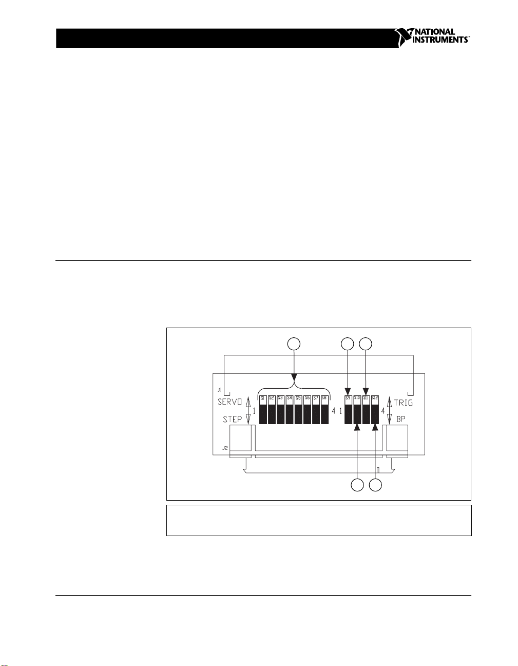
Figure 1 shows the location of the switches on the adapter.
21
345
1 Step/Servo Switch Bank
2 Axis 1 Trigger/Breakpoint Switch
3 Axis 2 Trigger/Breakpoint Switch
Figure 1.
ValueMotion™ is a trademark of National Instruments Corporation. Product and company names mentioned herein are trademarks or trade names
of their respective companies.
322543A-01 © Copyright 1999 National Instruments Corp. All rights reserved. August 1999
68M-50F Adapter Switch Locations
4 Axis 3 Trigger/Breakpoint Switch
5 Axis 4 Trigger/Breakpoint Switch
Page 2
Step/Servo Configuration
You must set all of the step/servo switches to match your motor type. Refer
to Figure 1 for the location of the step/servo switches. If you are controlling
a stepper motor, set all of the switches to STEP. If you are controlling a
servo motor, set all of the switches to SERVO.
Breakpoint/Trigger Configuration
You must set the breakpoint/trigger switches to match the desired operation
of your motion controller. Refer to Figure 1 for the location of the
breakpoint/trigger switches. Each breakpoint/trigger switch is associated
with a single axis and can be set individually for either breakpoint output
or trigger input operation. Set the switch to TRIG if the axis is used as a
trigger input. Set the switch to BP if the axis is used as a breakpoint output.
Installing Your Adapter
You have several options for installing your adapter, depending on the
devices you are connecting to each other and the cable that you are using to
make the connection. To install the adapter, make sure the power is off to
the controller and the accessory, and set the switches as required for your
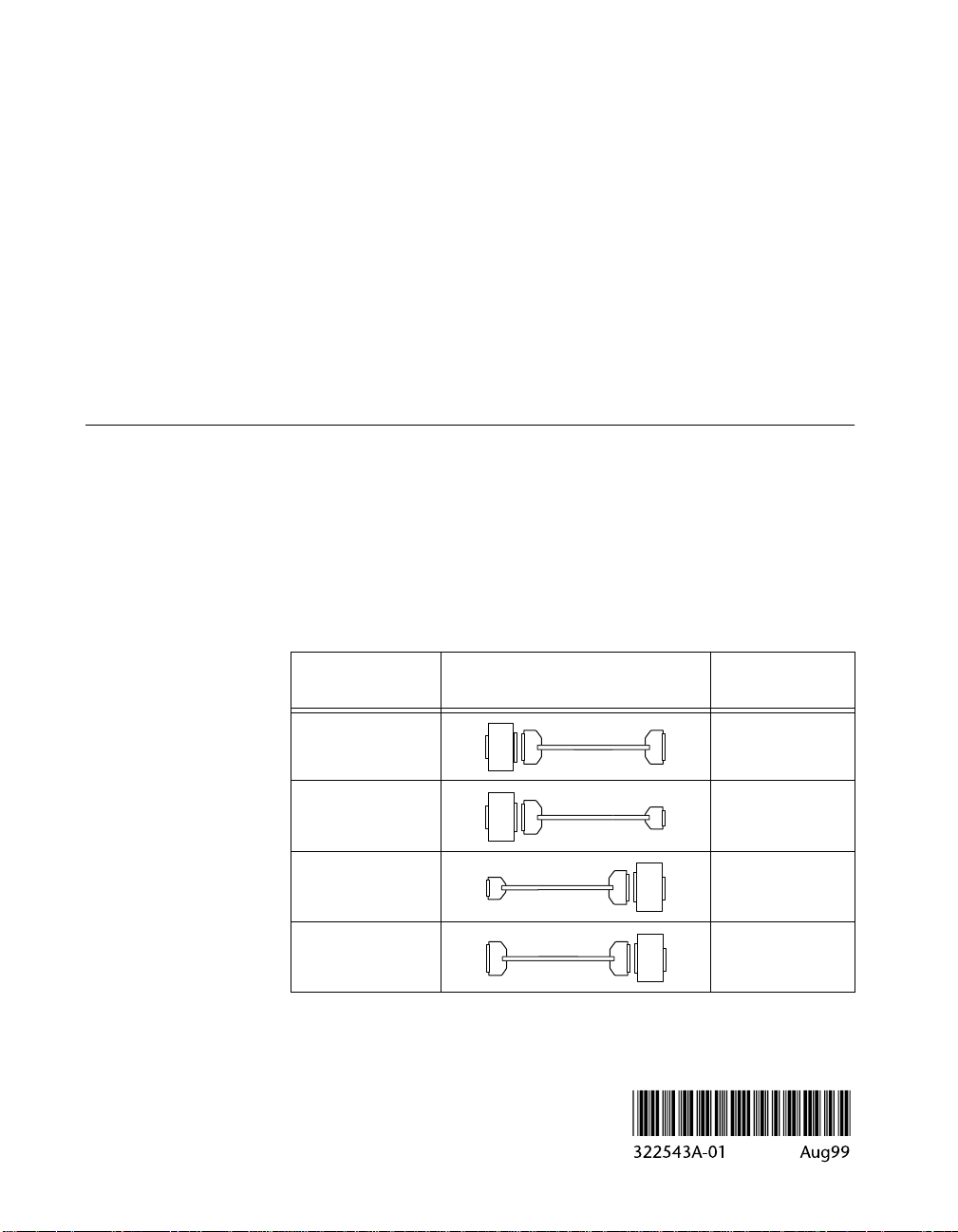
application. Then, refer to Table 1 to determine how to connect your
controller to your accessory using the adapter and the appropriate cable.
The adapter is shown as a box with an “A” inside it.
Table 1.
Controller
Connector
50-pin 68-pin SCSI-II
50-pin 68-pin VHDCI
68-pin VHDCI 50-pin
68-pin SCSI-II 50-pin
Adapter Connection Options
Cable
A
A
SH68-68-S
SH68-C68-S
SH68-C68-S
SH68-68-S
A
A
Accessory
Connector
 Loading...