

Page 1

Electronics
TM
Workbench
Multicap 9 Schematic Capture
User Guide
TitleShort-Hidden (cross reference text)
February 2006
371889A-01
Page 2

Support
Worldwide Technical Support and Product Information
ni.com
National Instruments Corporate Headquarters
11500 North Mopac Expressway Austin, Texas 78759-3504 USA Tel: 512 683 0100
Worldwide Offices
Australia 1800 300 800, Austria 43 0 662 45 79 90 0, Belgium 32 0 2 757 00 20, Brazil 55 11 3262 3599,
Canada 800 433 3488, China 86 21 6555 7838, Czech Republic 420 224 235 774, Denmark 45 45 76 26 00,
Finland 385 0 9 725 725 11, France 33 0 1 48 14 24 24, Germany 49 0 89 741 31 30, India 91 80 41190000,
Israel 972 0 3 6393737, Italy 39 02 413091, Japan 81 3 5472 2970, Korea 82 02 3451 3400,
Lebanon 961 0 1 33 28 28, Malaysia 1800 887710, Mexico 01 800 010 0793, Netherlands 31 0 348 433 466,
New Zealand 0800 553 322, Norway 47 0 66 90 76 60, Poland 48 22 3390150, Portugal 351 210 311 210,
Russia 7 095 783 68 51, Singapore 1800 226 5886, Slovenia 386 3 425 4200, South Africa 27 0 11 805 8197,
Spain 34 91 640 0085, Sweden 46 0 8 587 895 00, Switzerland 41 56 200 51 51, Taiwan 886 02 2377 2222,
Thailand 662 278 6777, United Kingdom 44 0 1635 523545
For further support information, refer to the Technical Support Resources and Professional Services page. To comment
on National Instruments documentation, refer to the National Instruments Web site at ni.com/info and enter the
info code feedback.
© 2006 National Instruments Corporation. All rights reserved.
Page 3

Important Information
Warranty
The media on which you receive National Instruments software are warranted not to fail to execute programming instructions, due to defects
in materials and workmanship, for a period of 90 days from date of shipment, as evidenced by receipts or other documentation. National
Instruments will, at its option, repair or replace software media that do not execute programming instructions if National Instruments receives
notice of such defects during the warranty period. National Instruments does not warrant that the operation of the software shall be
uninterrupted or error free.
A Return Material Authorization (RMA) number must be obtained from the factory and clearly marked on the outside of the package before
any equipment will be accepted for warranty work. National Instruments will pay the shipping costs of returning to the owner parts which are
covered by warranty.
National Instruments believes that the information in this document is accurate. The document has been carefully reviewed for technical
accuracy. In the event that technical or typographical errors exist, National Instruments reserves the right to make changes to subsequent
editions of this document without prior notice to holders of this edition. The reader should consult National Instruments if errors are suspected.
In no event shall National Instruments be liable for any damages arising out of or related to this document or the information contained in it.
E
XCEPT AS SPECIFIED HEREIN, NATIONAL INSTRUMENTS MAKES NO WARRANTIES, EXPRESS OR IMPLIED, AND SPECIF ICALLY DISCLAIMS ANY WARRANTY OF
MERCHANTABILITY OR FITNESS FOR A PARTICULAR PURPOSE. CUSTOMER’S RIGHT TO RECOVER DAMAGES CAUSED BY FAULT OR NEGLIGENCE ON THE PART OF
N
ATIONAL INSTRUMENTS SHALL BE LIMITED TO THE AMOUNT THERETOFORE PAID BY THE CUSTO MER. NATIONAL INSTRUMENTS WILL NOT BE LIA BLE FOR
DAMAGES RESULTIN G FROM LOSS OF DATA, PROFITS, USE OF PRODUCTS, OR INCIDENTAL OR CONSEQUENTIAL DAMAGES, EVEN IF ADVISED OF THE POSSIB ILITY
THEREOF. This limitation of the liability of National Instruments will apply regardless of the form of action, whether in contract or tort, including
negligence. Any action against National Instruments must be brought within one year after the cause of action accrues. National Instruments
shall not be liable for any delay in performance due to causes beyond its reasonable control. The warranty provided herein does not cover
damages, defects, malfunctions, or service failures caused by owner’s failure to follow the National Instruments installation, operation, or
maintenance instructions; owner’s modification of the product; owner’s abuse, misuse, or negligent acts; and power failure or surges, fire,
flood, accident, actions of third parties, or other events outside reasonable control.
Copyright
Under the copyright laws, this publication may not be reproduced or transmitted in any form, electronic or mechanical, including photocopying,
recording, storing in an information retrieval system, or translating, in whole or in part, without the prior written consent of National
Instruments Corporation.
National Instruments respects the intellectual property of others, and we ask our users to do the same. NI software is protected by copyright and other
intellectual property laws. Where NI software may be used to reproduce software or other materials belonging to others, you may use NI software only
to reproduce materials that you may reproduce in accordance with the terms of any applicable license or other legal restriction.
Trademarks
National Instruments, NI, ni.com, and LabVIEW are trademarks of National Instruments Corporation. Refer to the Terms of Use section
on
ni.com/legal for more information about National Instruments trademarks.
Other product and company names mentioned herein are trademarks or trade names of their respective companies.
Members of the National Instruments Alliance Partner Program are business entities independent from National Instruments and have no
agency, partnership, or joint-venture relationship with National Instruments.
Patents
For patents covering National Instruments products, refer to the appropriate location: Help»Patents in your software, the patents.txt file
on your CD, or ni.com/patents.
Some portions of this product are protected under United States Patent No. 6,560,572.
WARNING REGARDING USE OF NATIONAL INSTRUMENTS PRODUCTS
(1) NATIONAL INSTRUMENTS PRODUCTS ARE NOT DESIGNED WITH COMPONENTS AND TESTING FOR A LEVEL OF
RELIABILITY SUITABLE FOR USE IN OR IN CONNECTION WITH SURGICAL IMPLANTS OR AS CRITICAL COMPONENTS IN
ANY LIFE SUPPORT SYSTEMS WHOSE FAILURE TO PERFORM CAN REASONABLY BE EXPECTED TO CAUSE SIGNIFICANT
INJURY TO A HUMAN.
(2) IN ANY APPLICATION, INCLUDING THE ABOVE, RELIABILITY OF OPERATION OF THE SOFTWARE PRODUCTS CAN BE
IMPAIRED BY ADVERSE FACTORS, INCLUDING BUT NOT LIMITED TO FLUCTUATIONS IN ELECTRICAL POWER SUPPLY,
COMPUTER HARDWARE MALFUNCTIONS, COMPUTER OPERATING SYSTEM SOFTWARE FITNESS, FITNESS OF COMPILERS
AND DEVELOPMENT SOFTWARE USED TO DEVELOP AN APPLICATION, INSTALLATION ERRORS, SOFTWARE AND
HARDWARE COMPATIBILITY PROBLEMS, MALFUNCTIONS OR FAILURES OF ELECTRONIC MONITORING OR CONTROL
DEVICES, TRANSIENT FAILURES OF ELECTRONIC SYSTEMS (HARDWARE AND/OR SOFTWARE), UNANTICIPATED USES OR
MISUSES, OR ERRORS ON THE PART OF THE USER OR APPLICATIONS DESIGNER (ADVERSE FACTORS SUCH AS THESE ARE
HEREAFTER COLLECTIVELY TERMED “SYSTEM FAILURES”). ANY APPLICATION WHERE A SYSTEM FAILURE WOULD
CREATE A RISK OF HARM TO PROPERTY OR PERSONS (INCLUDING THE RISK OF BODILY INJURY AND DEATH) SHOULD
NOT BE RELIANT SOLELY UPON ONE FORM OF ELECTRONIC SYSTEM DUE TO THE RISK OF SYSTEM FAILURE. TO AVOID
DAMAGE, INJURY, OR DEATH, THE USER OR APPLICATION DESIGNER MUST TAKE REASONABLY PRUDENT STEPS TO
PROTECT AGAINST SYSTEM FAILURES, INCLUDING BUT NOT LIMITED TO BACK-UP OR SHUT DOWN MECHANISMS.
BECAUSE EACH END-USER SYSTEM IS CUSTOMIZED AND DIFFERS FROM NATIONAL INSTRUMENTS' TESTING
PLATFORMS AND BECAUSE A USER OR APPLICATION DESIGNER MAY USE NATIONAL INSTRUMENTS PRODUCTS IN
COMBINATION WITH OTHER PRODUCTS IN A MANNER NOT EVALUATED OR CONTEMPLATED BY NATIONAL
INSTRUMENTS, THE USER OR APPLICATION DESIGNER IS ULTIMATELY RESPONSIBLE FOR VERIFYING AND VALIDATING
THE SUITABILITY OF NATIONAL INSTRUMENTS PRODUCTS WHENEVER NATIONAL INSTRUMENTS PRODUCTS ARE
Page 4

Preface
Congratulations on choosing Multicap 9 from Electronics W orkbench. We are confident that it
will deliver years of increased productivity and superior designs.
Electronics Workbench is the world’s leading supplier of circuit design tools. Our products
are used by more customers than those of any other EDA vendor, so we are sure you will be
pleased with the value delivered by Multicap 9, and by any other Electronics Workbench
products you may select.
Documentation Conventions
When Multicap 9 guides refer to a toolbar button, an image of the button appears in the left
column.
When you see the icon in the left column, the functionality described is only available in
certain versions of Multicap 9. Please refer to the release notes for details.
Multicap 9 guides use the convention
“File/Open” means choose the Open command from the File menu.
Multicap 9 guides use the convention of an arrow () to indicate the start of procedural
information.
Multicap 9 guides use the construction C
hold down the “Ctrl” or “Alt” key on your keyboard and press another key.
Menu/Item to indicate menu commands. For example,
TRL-KEY and ALT-KEY to indicate when you must
The Multicap 9 Documentation Set
Multicap 9 documentation consists of this User Guide, the Component Reference Guide and
online help. All Multicap 9 users receive PDF versions of the User Guide and the
Component Reference Guide.
User Guide
The User Guide describes Multicap 9 and its many functions in detail. The guide is organized
based on the stages of circuit design and reporting, and explains all aspects of using Multicap
in detail. It also offers an introductory tutorial that takes you through these stages.
Page 5

Online Help
Multicap 9 offers a full help file system to support your use of the product.
Choose
detail, or choose
the component families provided with Multicap 9. Both are standard Windows help files,
offering a table of contents and index.
In addition, you can display context-sensitive help by pressing F1 from any command or
window, or by clicking the
Help/Multicap Help to display the help file that explains the Multicap 9 program in
Help/Component Reference to display the help file that contains details on all
Help button on any dialog box that offers it.
Adobe PDF Files
The User Guide and the Component Reference Guide, are provided on the documentation CD
as Adobe PDF files. T o open PDF files, you will need Adobe’s free Acrobat Reader program,
available for download at www.adobe.com.
License Agreement
Please read the license agreement found at www.electronicsworkbench.com carefully before
installing and using the software contained in this package. By installing and using the
software, you are agreeing to be bound by the terms of this license. If you do not agree to the
terms of this license, simply return the unused software within ten days to the place where you
obtained it and your money will be refunded.
Page 6

Table of Contents
1. Installing Multicap
1.1 Installation Requirements. . . . . . . . . . . . . . . . . . . . . . . . . . . . . . . . . . . . . . . . . . . . . . 1-2
1.2 Installation Overview . . . . . . . . . . . . . . . . . . . . . . . . . . . . . . . . . . . . . . . . . . . . . . . . . 1-3
1.3 Installing Multicap 9 . . . . . . . . . . . . . . . . . . . . . . . . . . . . . . . . . . . . . . . . . . . . . . . . . . 1-3
1.3.1 Before Installing Multicap 9 . . . . . . . . . . . . . . . . . . . . . . . . . . . . . . . . . . . . . 1-3
1.3.2 Single User Edition . . . . . . . . . . . . . . . . . . . . . . . . . . . . . . . . . . . . . . . . . . . 1-4
1.3.2.1 Installing the Single User Edition . . . . . . . . . . . . . . . . . . . . . . . . . 1-4
1.3.2.2 Requesting a Release Code for the Single User Version . . . . . . 1-4
1.3.3 Multi-Station Standalone Edition . . . . . . . . . . . . . . . . . . . . . . . . . . . . . . . . . 1-5
1.3.4 Network Version . . . . . . . . . . . . . . . . . . . . . . . . . . . . . . . . . . . . . . . . . . . . . . 1-5
1.3.4.1 Installing the Network Edition . . . . . . . . . . . . . . . . . . . . . . . . . . . 1-6
1.3.4.2 Entering the Release Code for the Network Edition . . . . . . . . . . 1-7
1.3.4.3 Workstation Setup . . . . . . . . . . . . . . . . . . . . . . . . . . . . . . . . . . . . 1-7
1.3.4.4 Setting User Permissions. . . . . . . . . . . . . . . . . . . . . . . . . . . . . . . 1-7
1.3.5 Changing Server Name and/or Port Number After Client Installation. . . . . 1-10
1.4 Network License Server . . . . . . . . . . . . . . . . . . . . . . . . . . . . . . . . . . . . . . . . . . . . . . 1-10
1.4.1 Administering the Network License Server . . . . . . . . . . . . . . . . . . . . . . . . 1-10
1.4.2 Administering Fixed Seat Licenses. . . . . . . . . . . . . . . . . . . . . . . . . . . . . . . 1-11
1.4.3 Reviewing License Server Events . . . . . . . . . . . . . . . . . . . . . . . . . . . . . . . 1-12
1.4.4 Troubleshooting . . . . . . . . . . . . . . . . . . . . . . . . . . . . . . . . . . . . . . . . . . . . . 1-12
1.5 Support and Upgrade . . . . . . . . . . . . . . . . . . . . . . . . . . . . . . . . . . . . . . . . . . . . . . . 1-14
1.5.1 Checking for Updates . . . . . . . . . . . . . . . . . . . . . . . . . . . . . . . . . . . . . . . . 1-14
1.5.2 Installing Updates . . . . . . . . . . . . . . . . . . . . . . . . . . . . . . . . . . . . . . . . . . . . 1-14
1.5.3 Viewing Messages . . . . . . . . . . . . . . . . . . . . . . . . . . . . . . . . . . . . . . . . . . . 1-15
1.5.4 Changing Settings . . . . . . . . . . . . . . . . . . . . . . . . . . . . . . . . . . . . . . . . . . . 1-15
1.6 Uninstalling Multicap 9 . . . . . . . . . . . . . . . . . . . . . . . . . . . . . . . . . . . . . . . . . . . . . . . 1-16
1.6.1 Uninstalling the Single User Version . . . . . . . . . . . . . . . . . . . . . . . . . . . . . 1-16
1.7 Uninstalling SUU . . . . . . . . . . . . . . . . . . . . . . . . . . . . . . . . . . . . . . . . . . . . . . . . . . . 1-16
1.8 Uninstalling a Site Version . . . . . . . . . . . . . . . . . . . . . . . . . . . . . . . . . . . . . . . . . . . . 1-17
1.8.1 Uninstalling Standalone Multi-Station Installation . . . . . . . . . . . . . . . . . . . 1-17
1.8.2 Uninstalling Network Installation . . . . . . . . . . . . . . . . . . . . . . . . . . . . . . . . 1-17
1.8.3 Uninstalling Combination Standalone Multi-Station
and Network Installations . . . . . . . . . . . . . . . . . . . . . . . . . . . . . . . . . . . . . . 1-17
1.9 Uninstalling NLS . . . . . . . . . . . . . . . . . . . . . . . . . . . . . . . . . . . . . . . . . . . . . . . . . . . 1-18
Multicap 9 User Guide i
Page 7

2. Multicap Tutorial
2.1 The Electronics Workbench Suite . . . . . . . . . . . . . . . . . . . . . . . . . . . . . . . . . . . . . . . .2-1
2.2 Multicap 9 Tutorial . . . . . . . . . . . . . . . . . . . . . . . . . . . . . . . . . . . . . . . . . . . . . . . . . . .2-2
2.2.1 Schematic Capture . . . . . . . . . . . . . . . . . . . . . . . . . . . . . . . . . . . . . . . . . . . .2-3
3. User Interface
3.1 Introduction to the Multicap Interface . . . . . . . . . . . . . . . . . . . . . . . . . . . . . . . . . . . . .3-3
3.2 Toolbars . . . . . . . . . . . . . . . . . . . . . . . . . . . . . . . . . . . . . . . . . . . . . . . . . . . . . . . . . . .3-4
3.2.1 Standard Toolbar . . . . . . . . . . . . . . . . . . . . . . . . . . . . . . . . . . . . . . . . . . . . .3-5
3.2.2 Main Toolbar . . . . . . . . . . . . . . . . . . . . . . . . . . . . . . . . . . . . . . . . . . . . . . . . .3-6
3.2.3 View Toolbar . . . . . . . . . . . . . . . . . . . . . . . . . . . . . . . . . . . . . . . . . . . . . . . . .3-7
3.2.4 Components Toolbar . . . . . . . . . . . . . . . . . . . . . . . . . . . . . . . . . . . . . . . . . .3-8
3.2.5 Virtual Toolbar . . . . . . . . . . . . . . . . . . . . . . . . . . . . . . . . . . . . . . . . . . . . . . . .3-9
3.2.6 Graphic Annotation Toolbar . . . . . . . . . . . . . . . . . . . . . . . . . . . . . . . . . . . .3-10
3.3 Using the Pop-up Menus . . . . . . . . . . . . . . . . . . . . . . . . . . . . . . . . . . . . . . . . . . . . .3-10
3.3.1 Pop-up From Circuit Window, with no Component Selected . . . . . . . . . . .3-11
3.3.2 Pop-up From a Selected Component . . . . . . . . . . . . . . . . . . . . . . . . . . . . .3-13
3.3.3 Pop-up From a Selected Wire . . . . . . . . . . . . . . . . . . . . . . . . . . . . . . . . . . .3-15
3.3.4 Pop-up From a Selected Text Block or Graphic . . . . . . . . . . . . . . . . . . . . .3-15
3.3.5 Pop-up From a Title Block . . . . . . . . . . . . . . . . . . . . . . . . . . . . . . . . . . . . .3-16
3.3.6 Pop-up from a Comment . . . . . . . . . . . . . . . . . . . . . . . . . . . . . . . . . . . . . .3-17
3.4 Setting Schematic Capture Preferences . . . . . . . . . . . . . . . . . . . . . . . . . . . . . . . . . .3-18
3.4.1 Using the Preferences Dialog Box . . . . . . . . . . . . . . . . . . . . . . . . . . . . . . .3-18
3.4.1.1 Preferences - Paths Tab . . . . . . . . . . . . . . . . . . . . . . . . . . . . . .3-19
3.4.1.2 Preferences - Save Tab . . . . . . . . . . . . . . . . . . . . . . . . . . . . . . .3-20
3.4.1.3 Preferences - Parts Tab . . . . . . . . . . . . . . . . . . . . . . . . . . . . . . .3-21
3.4.1.4 Preferences - General Tab . . . . . . . . . . . . . . . . . . . . . . . . . . . . .3-22
3.4.2 Using the Sheet Properties Dialog Box . . . . . . . . . . . . . . . . . . . . . . . . . . . .3-23
3.4.2.1 Sheet Properties - Circuit Tab . . . . . . . . . . . . . . . . . . . . . . . . . .3-24
3.4.2.2 Sheet Properties - Workspace Tab . . . . . . . . . . . . . . . . . . . . . .3-26
3.4.2.3 Sheet Properties - Wiring Tab . . . . . . . . . . . . . . . . . . . . . . . . . .3-27
3.4.2.4 Sheet Properties - Font Tab . . . . . . . . . . . . . . . . . . . . . . . . . . . .3-28
3.4.2.5 Sheet Properties - PCB Tab . . . . . . . . . . . . . . . . . . . . . . . . . . . .3-30
3.4.2.6 Sheet Properties - Visibility Tab . . . . . . . . . . . . . . . . . . . . . . . . .3-31
3.5 Design Toolbox . . . . . . . . . . . . . . . . . . . . . . . . . . . . . . . . . . . . . . . . . . . . . . . . . . . . .3-32
3.5.1 Visibility Tab . . . . . . . . . . . . . . . . . . . . . . . . . . . . . . . . . . . . . . . . . . . . . . . .3-32
3.5.2 Hierarchy Tab . . . . . . . . . . . . . . . . . . . . . . . . . . . . . . . . . . . . . . . . . . . . . . .3-33
ii Electronics Workbench
Page 8

3.6 Customizing the Interface . . . . . . . . . . . . . . . . . . . . . . . . . . . . . . . . . . . . . . . . . . . . 3-35
3.6.1 Commands tab . . . . . . . . . . . . . . . . . . . . . . . . . . . . . . . . . . . . . . . . . . . . . . 3-36
3.6.2 Toolbars tab . . . . . . . . . . . . . . . . . . . . . . . . . . . . . . . . . . . . . . . . . . . . . . . . 3-37
3.6.3 Keyboard tab. . . . . . . . . . . . . . . . . . . . . . . . . . . . . . . . . . . . . . . . . . . . . . . . 3-38
3.6.4 Menu tab . . . . . . . . . . . . . . . . . . . . . . . . . . . . . . . . . . . . . . . . . . . . . . . . . . 3-39
3.6.5 Options tab . . . . . . . . . . . . . . . . . . . . . . . . . . . . . . . . . . . . . . . . . . . . . . . . . 3-40
3.6.6 Customization Pop-up Menus . . . . . . . . . . . . . . . . . . . . . . . . . . . . . . . . . . 3-40
3.6.7 Other Customization Options . . . . . . . . . . . . . . . . . . . . . . . . . . . . . . . . . . . 3-41
4. Schematic Capture - Basics
4.1 Introduction to Schematic Capture . . . . . . . . . . . . . . . . . . . . . . . . . . . . . . . . . . . . . . 4-3
4.2 Working with Multiple Circuit Windows . . . . . . . . . . . . . . . . . . . . . . . . . . . . . . . . . . . 4-3
4.3 Selecting Components from the Database . . . . . . . . . . . . . . . . . . . . . . . . . . . . . . . . 4-3
4.4 Placing Components . . . . . . . . . . . . . . . . . . . . . . . . . . . . . . . . . . . . . . . . . . . . . . . . . 4-4
4.4.1 Using the place component browser . . . . . . . . . . . . . . . . . . . . . . . . . . . . . . 4-4
4.4.1.1 Multisection Components . . . . . . . . . . . . . . . . . . . . . . . . . . . . . . 4-7
4.4.1.2 Rotating/flipping a part during placement . . . . . . . . . . . . . . . . . . 4-9
4.4.1.3 Other buttons . . . . . . . . . . . . . . . . . . . . . . . . . . . . . . . . . . . . . . . . 4-9
4.4.2 Placing Virtual Components . . . . . . . . . . . . . . . . . . . . . . . . . . . . . . . . . . . . . 4-9
4.4.2.1 Virtual component toolbars. . . . . . . . . . . . . . . . . . . . . . . . . . . . . 4-10
4.4.3 Using the In Use List . . . . . . . . . . . . . . . . . . . . . . . . . . . . . . . . . . . . . . . . . 4-13
4.4.4 Selecting Placed Components . . . . . . . . . . . . . . . . . . . . . . . . . . . . . . . . . . 4-13
4.4.5 Moving a Placed Component . . . . . . . . . . . . . . . . . . . . . . . . . . . . . . . . . . . 4-14
4.4.6 Copying a Placed Component . . . . . . . . . . . . . . . . . . . . . . . . . . . . . . . . . . 4-16
4.4.7 Replacing a Placed Component . . . . . . . . . . . . . . . . . . . . . . . . . . . . . . . . 4-17
4.4.8 Controlling Component Color . . . . . . . . . . . . . . . . . . . . . . . . . . . . . . . . . . . 4-18
4.5 Wiring Components . . . . . . . . . . . . . . . . . . . . . . . . . . . . . . . . . . . . . . . . . . . . . . . . . 4-18
4.5.1 Wiring Components Automatically . . . . . . . . . . . . . . . . . . . . . . . . . . . . . . . 4-19
4.5.1.1 Autowire of Touching Pins . . . . . . . . . . . . . . . . . . . . . . . . . . . . . 4-20
4.5.2 Wiring Components Manually . . . . . . . . . . . . . . . . . . . . . . . . . . . . . . . . . . 4-22
4.5.3 Combining Automatic and Manual Wiring . . . . . . . . . . . . . . . . . . . . . . . . . 4-23
4.5.4 Marking Pins for No Connection . . . . . . . . . . . . . . . . . . . . . . . . . . . . . . . . 4-23
4.5.5 Placing Wires Directly Onto Workspace . . . . . . . . . . . . . . . . . . . . . . . . . . 4-26
4.5.6 Setting Wiring Preferences . . . . . . . . . . . . . . . . . . . . . . . . . . . . . . . . . . . . 4-26
4.5.7 Modifying the Wire Path . . . . . . . . . . . . . . . . . . . . . . . . . . . . . . . . . . . . . . . 4-27
4.5.8 Controlling Wire Color . . . . . . . . . . . . . . . . . . . . . . . . . . . . . . . . . . . . . . . . 4-27
4.5.9 Moving a Wire . . . . . . . . . . . . . . . . . . . . . . . . . . . . . . . . . . . . . . . . . . . . . . 4-28
4.5.10 Virtual Wiring . . . . . . . . . . . . . . . . . . . . . . . . . . . . . . . . . . . . . . . . . . . . . . . 4-28
Multicap 9 User Guide iii
Page 9

4.6 Manually Adding a Junction (Connector) . . . . . . . . . . . . . . . . . . . . . . . . . . . . . . . . .4-29
4.7 Rotating/Flipping Placed Components . . . . . . . . . . . . . . . . . . . . . . . . . . . . . . . . . . .4-30
4.8 Finding Components in Your Circuit . . . . . . . . . . . . . . . . . . . . . . . . . . . . . . . . . . . . .4-32
4.9 Labeling . . . . . . . . . . . . . . . . . . . . . . . . . . . . . . . . . . . . . . . . . . . . . . . . . . . . . . . . . .4-33
4.9.1 Modifying Component Labels and Attributes . . . . . . . . . . . . . . . . . . . . . . .4-34
4.9.2 Modifying Net Names . . . . . . . . . . . . . . . . . . . . . . . . . . . . . . . . . . . . . . . . .4-35
4.9.3 Adding a Title Block . . . . . . . . . . . . . . . . . . . . . . . . . . . . . . . . . . . . . . . . . .4-36
4.9.3.1 Entering the Title Block Contents . . . . . . . . . . . . . . . . . . . . . . . .4-37
4.9.4 Adding Miscellaneous Text . . . . . . . . . . . . . . . . . . . . . . . . . . . . . . . . . . . . .4-39
4.9.5 Adding a Comment . . . . . . . . . . . . . . . . . . . . . . . . . . . . . . . . . . . . . . . . . . .4-40
4.9.6 Graphic Annotation . . . . . . . . . . . . . . . . . . . . . . . . . . . . . . . . . . . . . . . . . . .4-43
4.9.7 Capturing Screen Area . . . . . . . . . . . . . . . . . . . . . . . . . . . . . . . . . . . . . . . .4-45
4.10 Circuit Description Box . . . . . . . . . . . . . . . . . . . . . . . . . . . . . . . . . . . . . . . . . . . . . . .4-47
4.10.1 Formatting the Circuit Description Box . . . . . . . . . . . . . . . . . . . . . . . . . . . .4-47
4.10.1.1 Formatting Circuit Description Box Text . . . . . . . . . . . . . . . . . . .4-48
4.10.1.2 Paragraph Dialog Box . . . . . . . . . . . . . . . . . . . . . . . . . . . . . . . .4-48
4.10.1.3 Tabs Dialog Box . . . . . . . . . . . . . . . . . . . . . . . . . . . . . . . . . . . . .4-49
4.10.1.4 Date and Time Dialog Box . . . . . . . . . . . . . . . . . . . . . . . . . . . . .4-49
4.10.1.5 Options Dialog Box . . . . . . . . . . . . . . . . . . . . . . . . . . . . . . . . . . .4-50
4.10.1.6 Insert Object Dialog Box . . . . . . . . . . . . . . . . . . . . . . . . . . . . . . .4-50
4.10.2 Description Edit Bar . . . . . . . . . . . . . . . . . . . . . . . . . . . . . . . . . . . . . . . . .4-51
4.11 Linking a Form to a Circuit. . . . . . . . . . . . . . . . . . . . . . . . . . . . . . . . . . . . . . . . . . . . .4-52
4.11.1 Creating Forms . . . . . . . . . . . . . . . . . . . . . . . . . . . . . . . . . . . . . . . . . . . . . .4-53
4.11.2 Setting Form Submission Options . . . . . . . . . . . . . . . . . . . . . . . . . . . . . . .4-54
4.11.3 Completing Forms . . . . . . . . . . . . . . . . . . . . . . . . . . . . . . . . . . . . . . . . . . . .4-55
4.12 Printing the Circuit . . . . . . . . . . . . . . . . . . . . . . . . . . . . . . . . . . . . . . . . . . . . . . . . . .4-56
5. Schematic Capture - Advanced Functions
5.1 Placed Component Properties . . . . . . . . . . . . . . . . . . . . . . . . . . . . . . . . . . . . . . . . . .5-2
5.1.1 Displaying Identifying Information about a Placed Component . . . . . . . . . .5-2
5.1.2 Viewing a Placed Component’s Value. . . . . . . . . . . . . . . . . . . . . . . . . . . . . .5-3
5.1.2.1 Real Components . . . . . . . . . . . . . . . . . . . . . . . . . . . . . . . . . . . . .5-3
5.1.2.2 Edit Footprint Dialog Box . . . . . . . . . . . . . . . . . . . . . . . . . . . . . . .5-5
5.1.2.3 Virtual Components . . . . . . . . . . . . . . . . . . . . . . . . . . . . . . . . . . .5-6
iv Electronics Workbench
Page 10

5.2 The Spreadsheet View . . . . . . . . . . . . . . . . . . . . . . . . . . . . . . . . . . . . . . . . . . . . . . . 5-7
5.2.1 Spreadsheet View Results Tab . . . . . . . . . . . . . . . . . . . . . . . . . . . . . . . . . . 5-7
5.2.2 Spreadsheet View Nets Tab . . . . . . . . . . . . . . . . . . . . . . . . . . . . . . . . . . . . 5-8
5.2.3 Spreadsheet View Components Tab . . . . . . . . . . . . . . . . . . . . . . . . . . . . . . 5-9
5.2.4 Spreadsheet View PCB Layers Tab . . . . . . . . . . . . . . . . . . . . . . . . . . . . . 5-12
5.2.5 Spreadsheet View Buttons . . . . . . . . . . . . . . . . . . . . . . . . . . . . . . . . . . . . . 5-12
5.3 Title Block Editor . . . . . . . . . . . . . . . . . . . . . . . . . . . . . . . . . . . . . . . . . . . . . . . . . . . 5-13
5.3.1 Enter Text Dialog Box . . . . . . . . . . . . . . . . . . . . . . . . . . . . . . . . . . . . . . . . 5-15
5.3.2 Placing Fields . . . . . . . . . . . . . . . . . . . . . . . . . . . . . . . . . . . . . . . . . . . . . . . 5-16
5.3.2.1 Field Codes . . . . . . . . . . . . . . . . . . . . . . . . . . . . . . . . . . . . . . . . 5-18
5.3.3 Title Block Editor Spreadsheet View . . . . . . . . . . . . . . . . . . . . . . . . . . . . . 5-19
5.3.4 Title Block Editor Menus . . . . . . . . . . . . . . . . . . . . . . . . . . . . . . . . . . . . . . 5-20
5.3.4.1 File Menu . . . . . . . . . . . . . . . . . . . . . . . . . . . . . . . . . . . . . . . . . . 5-20
5.3.4.2 Edit Menu . . . . . . . . . . . . . . . . . . . . . . . . . . . . . . . . . . . . . . . . . 5-21
5.3.4.3 View Menu . . . . . . . . . . . . . . . . . . . . . . . . . . . . . . . . . . . . . . . . . 5-22
5.3.4.4 Fields Menu . . . . . . . . . . . . . . . . . . . . . . . . . . . . . . . . . . . . . . . . 5-23
5.3.4.5 Graphics Menu . . . . . . . . . . . . . . . . . . . . . . . . . . . . . . . . . . . . . 5-24
5.3.4.6 Tools Menu . . . . . . . . . . . . . . . . . . . . . . . . . . . . . . . . . . . . . . . . 5-25
5.3.4.7 Help Menu . . . . . . . . . . . . . . . . . . . . . . . . . . . . . . . . . . . . . . . . . 5-26
5.3.4.8 Pop-up Menus . . . . . . . . . . . . . . . . . . . . . . . . . . . . . . . . . . . . . . 5-26
5.3.5 Toolbars . . . . . . . . . . . . . . . . . . . . . . . . . . . . . . . . . . . . . . . . . . . . . . . . . . . 5-27
5.3.5.1 Standard Toolbar . . . . . . . . . . . . . . . . . . . . . . . . . . . . . . . . . . . . 5-27
5.3.5.2 Zoom Toolbar . . . . . . . . . . . . . . . . . . . . . . . . . . . . . . . . . . . . . . 5-28
5.3.5.3 Draw Tools Toolbar . . . . . . . . . . . . . . . . . . . . . . . . . . . . . . . . . . 5-29
5.3.5.4 Drawing Toolbar . . . . . . . . . . . . . . . . . . . . . . . . . . . . . . . . . . . . 5-30
5.4 Electrical Rules Checking . . . . . . . . . . . . . . . . . . . . . . . . . . . . . . . . . . . . . . . . . . . . 5-32
5.4.1 ERC Options Tab . . . . . . . . . . . . . . . . . . . . . . . . . . . . . . . . . . . . . . . . . . . . 5-35
5.4.1.1 Clearing ERC Markers . . . . . . . . . . . . . . . . . . . . . . . . . . . . . . . . 5-36
5.4.2 ERC Rules Tab . . . . . . . . . . . . . . . . . . . . . . . . . . . . . . . . . . . . . . . . . . . . . 5-37
5.4.3 Component’s Pins Tab . . . . . . . . . . . . . . . . . . . . . . . . . . . . . . . . . . . . . . . . 5-39
6. Working with Larger Designs
6.1 Flat Multi-sheet Design . . . . . . . . . . . . . . . . . . . . . . . . . . . . . . . . . . . . . . . . . . . . . . . 6-2
6.1.1 Delete Multi-page Dialog Box . . . . . . . . . . . . . . . . . . . . . . . . . . . . . . . . . . . 6-3
6.2 Hierarchical Design . . . . . . . . . . . . . . . . . . . . . . . . . . . . . . . . . . . . . . . . . . . . . . . . . . 6-3
6.2.1 Nested Circuits . . . . . . . . . . . . . . . . . . . . . . . . . . . . . . . . . . . . . . . . . . . . . . . 6-4
6.2.2 Component Numbering in Nested Circuits . . . . . . . . . . . . . . . . . . . . . . . . . . 6-4
6.2.3 Net Numbering in Nested Circuits. . . . . . . . . . . . . . . . . . . . . . . . . . . . . . . . . 6-5
6.2.4 Global Nets. . . . . . . . . . . . . . . . . . . . . . . . . . . . . . . . . . . . . . . . . . . . . . . . . . 6-6
Multicap 9 User Guide v
Page 11

6.2.5 Adding a Hierarchical Block . . . . . . . . . . . . . . . . . . . . . . . . . . . . . . . . . . . . .6-7
6.2.5.1 Placing a HB from an Existing File . . . . . . . . . . . . . . . . . . . . . . . .6-8
6.2.5.2 Replacing Components with an HB. . . . . . . . . . . . . . . . . . . . . . . .6-9
6.2.6 Adding a Subcircuit . . . . . . . . . . . . . . . . . . . . . . . . . . . . . . . . . . . . . . . . . . . .6-9
6.2.6.1 Replacing Components with a SC . . . . . . . . . . . . . . . . . . . . . . .6-11
6.2.7 Viewing Parent Sheet . . . . . . . . . . . . . . . . . . . . . . . . . . . . . . . . . . . . . . . . .6-11
6.3 Renaming Component Instances . . . . . . . . . . . . . . . . . . . . . . . . . . . . . . . . . . . . . . .6-11
6.3.1 Reference Designator Prefix Setup Dialog . . . . . . . . . . . . . . . . . . . . . . . . .6-13
6.4 Buses . . . . . . . . . . . . . . . . . . . . . . . . . . . . . . . . . . . . . . . . . . . . . . . . . . . . . . . . . . . .6-16
6.4.1 Placing a Bus . . . . . . . . . . . . . . . . . . . . . . . . . . . . . . . . . . . . . . . . . . . . . . .6-18
6.4.1.1 Placing a bus across Multi-pages . . . . . . . . . . . . . . . . . . . . . . . .6-19
6.4.1.2 Connecting Buses to HB/SCs . . . . . . . . . . . . . . . . . . . . . . . . . .6-19
6.4.2 Bus Properties . . . . . . . . . . . . . . . . . . . . . . . . . . . . . . . . . . . . . . . . . . . . . .6-21
6.4.2.1 Adding buslines to a Bus . . . . . . . . . . . . . . . . . . . . . . . . . . . . . .6-21
6.4.2.2 Deleting Buslines from a Bus . . . . . . . . . . . . . . . . . . . . . . . . . . .6-23
6.4.2.3 Renaming Buslines in a Bus . . . . . . . . . . . . . . . . . . . . . . . . . . .6-23
6.4.3 Merging Buses . . . . . . . . . . . . . . . . . . . . . . . . . . . . . . . . . . . . . . . . . . . . . .6-24
6.4.4 Wiring to a Bus. . . . . . . . . . . . . . . . . . . . . . . . . . . . . . . . . . . . . . . . . . . . . . .6-25
6.4.5 Bus Vector Connect . . . . . . . . . . . . . . . . . . . . . . . . . . . . . . . . . . . . . . . . . .6-27
6.5 Variants . . . . . . . . . . . . . . . . . . . . . . . . . . . . . . . . . . . . . . . . . . . . . . . . . . . . . . . . . . .6-34
6.5.1 Setting Up Variants . . . . . . . . . . . . . . . . . . . . . . . . . . . . . . . . . . . . . . . . . . .6-34
6.5.2 Placing Parts in Variants . . . . . . . . . . . . . . . . . . . . . . . . . . . . . . . . . . . . . . .6-37
6.5.2.1 Assigning Variant Status to Components . . . . . . . . . . . . . . . . . .6-38
6.5.2.2 Assigning Variant Status to Nested Circuits . . . . . . . . . . . . . . . .6-43
6.5.2.3 Setting the Active Variant . . . . . . . . . . . . . . . . . . . . . . . . . . . . . .6-44
6.6 Project Management and Version Control . . . . . . . . . . . . . . . . . . . . . . . . . . . . . . . .6-47
6.6.1 Setting up Projects . . . . . . . . . . . . . . . . . . . . . . . . . . . . . . . . . . . . . . . . . . .6-48
6.6.2 Working with Projects . . . . . . . . . . . . . . . . . . . . . . . . . . . . . . . . . . . . . . . . .6-49
6.6.3 Working with Files Contained in Projects . . . . . . . . . . . . . . . . . . . . . . . . . .6-50
6.6.4 Version Control . . . . . . . . . . . . . . . . . . . . . . . . . . . . . . . . . . . . . . . . . . . . . .6-51
7. Components
7.1 Structure of the Component Database . . . . . . . . . . . . . . . . . . . . . . . . . . . . . . . . . . . .7-2
7.1.1 Database Levels . . . . . . . . . . . . . . . . . . . . . . . . . . . . . . . . . . . . . . . . . . . . . .7-2
7.1.2 Classification of Components in the Database . . . . . . . . . . . . . . . . . . . . . . .7-3
7.2 Locating Components in the Database . . . . . . . . . . . . . . . . . . . . . . . . . . . . . . . . . . . .7-4
7.2.1 Browsing for Components . . . . . . . . . . . . . . . . . . . . . . . . . . . . . . . . . . . . . . .7-4
7.2.2 Searching for Components . . . . . . . . . . . . . . . . . . . . . . . . . . . . . . . . . . . . . .7-4
vi Electronics Workbench
Page 12

7.3 Types of Information Stored for Components . . . . . . . . . . . . . . . . . . . . . . . . . . . . . . 7-6
7.3.1 Pre-Defined Fields . . . . . . . . . . . . . . . . . . . . . . . . . . . . . . . . . . . . . . . . . . . . 7-7
7.3.1.1 General Information . . . . . . . . . . . . . . . . . . . . . . . . . . . . . . . . . . . 7-7
7.3.2 User Fields . . . . . . . . . . . . . . . . . . . . . . . . . . . . . . . . . . . . . . . . . . . . . . . . . . 7-7
7.4 Managing the Database . . . . . . . . . . . . . . . . . . . . . . . . . . . . . . . . . . . . . . . . . . . . . . . 7-8
7.4.1 Filtering Displayed Components . . . . . . . . . . . . . . . . . . . . . . . . . . . . . . . . . 7-9
7.4.2 Managing Families . . . . . . . . . . . . . . . . . . . . . . . . . . . . . . . . . . . . . . . . . . . 7-10
7.4.3 Modifying User Field Titles . . . . . . . . . . . . . . . . . . . . . . . . . . . . . . . . . . . . . 7-11
7.4.4 Deleting Components . . . . . . . . . . . . . . . . . . . . . . . . . . . . . . . . . . . . . . . . 7-12
7.4.5 Copying Components . . . . . . . . . . . . . . . . . . . . . . . . . . . . . . . . . . . . . . . . 7-13
7.4.6 Saving Placed Components . . . . . . . . . . . . . . . . . . . . . . . . . . . . . . . . . . . . 7-15
7.4.7 Moving Components Between Databases . . . . . . . . . . . . . . . . . . . . . . . . . 7-15
7.4.8 Displaying Database Information . . . . . . . . . . . . . . . . . . . . . . . . . . . . . . . . 7-16
7.4.9 Editing Components . . . . . . . . . . . . . . . . . . . . . . . . . . . . . . . . . . . . . . . . . . 7-16
7.5 Converting 2001 or V7 Databases . . . . . . . . . . . . . . . . . . . . . . . . . . . . . . . . . . . . . . 7-17
7.6 Updating Components from Databases . . . . . . . . . . . . . . . . . . . . . . . . . . . . . . . . . . 7-18
7.7 Merging Databases . . . . . . . . . . . . . . . . . . . . . . . . . . . . . . . . . . . . . . . . . . . . . . . . . 7-19
8. Component Editing
8.1 Introduction to Component Editing . . . . . . . . . . . . . . . . . . . . . . . . . . . . . . . . . . . . . . 8-2
8.2 Adding Components with the Component Wizard . . . . . . . . . . . . . . . . . . . . . . . . . . . 8-3
8.2.1 Using an Existing Symbol File . . . . . . . . . . . . . . . . . . . . . . . . . . . . . . . . . . . 8-9
8.3 Editing Components . . . . . . . . . . . . . . . . . . . . . . . . . . . . . . . . . . . . . . . . . . . . . . . . 8-10
8.4 Editing a Component’s General Properties . . . . . . . . . . . . . . . . . . . . . . . . . . . . . . . 8-12
8.5 Editing a Component’s Symbol . . . . . . . . . . . . . . . . . . . . . . . . . . . . . . . . . . . . . . . . 8-13
8.5.1 Copying a Component’s Symbol . . . . . . . . . . . . . . . . . . . . . . . . . . . . . . . . 8-14
8.5.1.1 Using “Copy To...” . . . . . . . . . . . . . . . . . . . . . . . . . . . . . . . . . . . 8-15
8.5.2 Creating and Editing a Component’s Symbol with the Symbol Editor . . . . 8-15
8.5.2.1 Symbol Editor Spreadsheet View . . . . . . . . . . . . . . . . . . . . . . . 8-17
8.5.2.2 Working with the Symbol Editor . . . . . . . . . . . . . . . . . . . . . . . . . 8-20
8.5.2.3 Enter Text Dialog Box . . . . . . . . . . . . . . . . . . . . . . . . . . . . . . . . 8-24
8.5.2.4 In-Place Edit Mode . . . . . . . . . . . . . . . . . . . . . . . . . . . . . . . . . . 8-24
8.5.2.5 Symbol Editor Menus . . . . . . . . . . . . . . . . . . . . . . . . . . . . . . . . 8-25
8.5.2.6 Toolbars . . . . . . . . . . . . . . . . . . . . . . . . . . . . . . . . . . . . . . . . . . 8-31
8.6 Editing a Component Pin Model . . . . . . . . . . . . . . . . . . . . . . . . . . . . . . . . . . . . . . . 8-37
Multicap 9 User Guide vii
Page 13

8.7 Editing a Component’s Footprint . . . . . . . . . . . . . . . . . . . . . . . . . . . . . . . . . . . . . . .8-38
8.7.1 Select a Footprint dialog box . . . . . . . . . . . . . . . . . . . . . . . . . . . . . . . . . . .8-39
8.7.1.1 Filter dialog box . . . . . . . . . . . . . . . . . . . . . . . . . . . . . . . . . . . . .8-40
8.7.2 Add a Footprint dialog box . . . . . . . . . . . . . . . . . . . . . . . . . . . . . . . . . . . . .8-44
8.7.3 Advanced Pin Mapping Dialog . . . . . . . . . . . . . . . . . . . . . . . . . . . . . . . . . .8-45
8.8 Editing User Fields . . . . . . . . . . . . . . . . . . . . . . . . . . . . . . . . . . . . . . . . . . . . . . . . . .8-49
9. Reports
9.1 Bill of Materials . . . . . . . . . . . . . . . . . . . . . . . . . . . . . . . . . . . . . . . . . . . . . . . . . . . . . .9-2
9.1.1 Using the BOM Report . . . . . . . . . . . . . . . . . . . . . . . . . . . . . . . . . . . . . . . . .9-3
9.2 Component Detail Report . . . . . . . . . . . . . . . . . . . . . . . . . . . . . . . . . . . . . . . . . . . . . .9-5
9.2.1 Using the Component Detail Report . . . . . . . . . . . . . . . . . . . . . . . . . . . . . . .9-5
9.3 Netlist Report . . . . . . . . . . . . . . . . . . . . . . . . . . . . . . . . . . . . . . . . . . . . . . . . . . . . . . .9-6
9.3.1 Using the Netlist Report . . . . . . . . . . . . . . . . . . . . . . . . . . . . . . . . . . . . . . . .9-7
9.4 Schematic Statistics Report . . . . . . . . . . . . . . . . . . . . . . . . . . . . . . . . . . . . . . . . . . . .9-8
9.4.1 Using the Schematic Statistics Report . . . . . . . . . . . . . . . . . . . . . . . . . . . . .9-9
9.5 Spare Gates Report . . . . . . . . . . . . . . . . . . . . . . . . . . . . . . . . . . . . . . . . . . . . . . . . . .9-9
9.5.1 Using the Spare Gates Report . . . . . . . . . . . . . . . . . . . . . . . . . . . . . . . . . .9-10
9.6 Cross Reference Report . . . . . . . . . . . . . . . . . . . . . . . . . . . . . . . . . . . . . . . . . . . . . .9-11
9.6.1 Using the Cross Reference Report . . . . . . . . . . . . . . . . . . . . . . . . . . . . . . .9-11
9.7 Variants Filter Dialog Box . . . . . . . . . . . . . . . . . . . . . . . . . . . . . . . . . . . . . . . . . . . . .9-12
10. Transfer/Communication
10.1 Exporting to PCB layout . . . . . . . . . . . . . . . . . . . . . . . . . . . . . . . . . . . . . . . . . . . . . .10-1
10.1.1 Transferring from Multicap to Ultiboard for PCB Layout . . . . . . . . . . . . . . .10-3
10.1.2 Transferring to Other PCB Layout Packages . . . . . . . . . . . . . . . . . . . . . . .10-3
10.1.3 Multisection Components . . . . . . . . . . . . . . . . . . . . . . . . . . . . . . . . . . . . . .10-4
10.2 Forward Annotation . . . . . . . . . . . . . . . . . . . . . . . . . . . . . . . . . . . . . . . . . . . . . . . . .10-4
10.3 Back Annotation . . . . . . . . . . . . . . . . . . . . . . . . . . . . . . . . . . . . . . . . . . . . . . . . . . . .10-4
10.4 Importing Files with Other Formats . . . . . . . . . . . . . . . . . . . . . . . . . . . . . . . . . . . . . .10-5
10.5 Internet Design Sharing . . . . . . . . . . . . . . . . . . . . . . . . . . . . . . . . . . . . . . . . . . . . . .10-6
viii Electronics Workbench
Page 14

Appendix A
A.1 Multicap Menus. . . . . . . . . . . . . . . . . . . . . . . . . . . . . . . . . . . . . . . . . . . . . . . . . . . . . .A-1
A.1.1 File Menu . . . . . . . . . . . . . . . . . . . . . . . . . . . . . . . . . . . . . . . . . . . . . . . . . . . A-1
A.1.1.1 File/New/Schematic Capture . . . . . . . . . . . . . . . . . . . . . . . . . . . . A-1
A.1.1.2 File/Open . . . . . . . . . . . . . . . . . . . . . . . . . . . . . . . . . . . . . . . . . . . A-2
A.1.1.3 File/Open Samples . . . . . . . . . . . . . . . . . . . . . . . . . . . . . . . . . . . A-2
A.1.1.4 File/Close . . . . . . . . . . . . . . . . . . . . . . . . . . . . . . . . . . . . . . . . . . A-2
A.1.1.5 File/Close All . . . . . . . . . . . . . . . . . . . . . . . . . . . . . . . . . . . . . . . .A-2
A.1.1.6 File/Save . . . . . . . . . . . . . . . . . . . . . . . . . . . . . . . . . . . . . . . . . . . A-2
A.1.1.7 File/Save As . . . . . . . . . . . . . . . . . . . . . . . . . . . . . . . . . . . . . . . . A-2
A.1.1.8 File/Save All . . . . . . . . . . . . . . . . . . . . . . . . . . . . . . . . . . . . . . . . A-2
A.1.1.9 File/New Project . . . . . . . . . . . . . . . . . . . . . . . . . . . . . . . . . . . . . A-3
A.1.1.10 File/Open Project . . . . . . . . . . . . . . . . . . . . . . . . . . . . . . . . . . . . . A-3
A.1.1.11 File/Save Project . . . . . . . . . . . . . . . . . . . . . . . . . . . . . . . . . . . . . A-3
A.1.1.12 File/Close Project . . . . . . . . . . . . . . . . . . . . . . . . . . . . . . . . . . . . A-3
A.1.1.13 File/Version Control . . . . . . . . . . . . . . . . . . . . . . . . . . . . . . . . . . . A-3
A.1.1.14 File/Print . . . . . . . . . . . . . . . . . . . . . . . . . . . . . . . . . . . . . . . . . . . A-3
A.1.1.15 File/Print Preview . . . . . . . . . . . . . . . . . . . . . . . . . . . . . . . . . . . . .A-3
A.1.1.16 File/Print Options/Printer Setup . . . . . . . . . . . . . . . . . . . . . . . . . . A-3
A.1.1.17 File/Print Options/Print Circuit Setup . . . . . . . . . . . . . . . . . . . . . . A-3
A.1.1.18 File/Recent Circuits . . . . . . . . . . . . . . . . . . . . . . . . . . . . . . . . . . . A-4
A.1.1.19 File/Recent Projects . . . . . . . . . . . . . . . . . . . . . . . . . . . . . . . . . . A-4
A.1.1.20 File/Exit . . . . . . . . . . . . . . . . . . . . . . . . . . . . . . . . . . . . . . . . . . . . A-4
A.1.2 Edit Menu . . . . . . . . . . . . . . . . . . . . . . . . . . . . . . . . . . . . . . . . . . . . . . . . . . . A-4
A.1.2.1 Edit/Undo . . . . . . . . . . . . . . . . . . . . . . . . . . . . . . . . . . . . . . . . . . . A-4
A.1.2.2 Edit/Redo . . . . . . . . . . . . . . . . . . . . . . . . . . . . . . . . . . . . . . . . . . . A-4
A.1.2.3 Edit/Cut. . . . . . . . . . . . . . . . . . . . . . . . . . . . . . . . . . . . . . . . . . . . . A-4
A.1.2.4 Edit/Copy . . . . . . . . . . . . . . . . . . . . . . . . . . . . . . . . . . . . . . . . . . . A-4
A.1.2.5 Edit/Paste . . . . . . . . . . . . . . . . . . . . . . . . . . . . . . . . . . . . . . . . . .A-5
A.1.2.6 Edit/Delete . . . . . . . . . . . . . . . . . . . . . . . . . . . . . . . . . . . . . . . . . . A-5
A.1.2.7 Edit/Select All . . . . . . . . . . . . . . . . . . . . . . . . . . . . . . . . . . . . . . . A-5
A.1.2.8 Edit/Delete Multi-Page . . . . . . . . . . . . . . . . . . . . . . . . . . . . . . . . . A-5
A.1.2.9 Edit/Paste as Subcircuit . . . . . . . . . . . . . . . . . . . . . . . . . . . . . . . .A-5
A.1.2.10 Edit/Find . . . . . . . . . . . . . . . . . . . . . . . . . . . . . . . . . . . . . . . . . . . A-5
A.1.2.11 Edit/Graphic Annotation . . . . . . . . . . . . . . . . . . . . . . . . . . . . . . . A-6
A.1.2.12 Edit/Order . . . . . . . . . . . . . . . . . . . . . . . . . . . . . . . . . . . . . . . . . .A-6
A.1.2.13 Edit/Assign to Layer . . . . . . . . . . . . . . . . . . . . . . . . . . . . . . . . . . A-6
A.1.2.14 Edit/Layer Settings . . . . . . . . . . . . . . . . . . . . . . . . . . . . . . . . . . . . A-6
A.1.2.15 Edit/Title Block Position . . . . . . . . . . . . . . . . . . . . . . . . . . . . . . . . A-6
A.1.2.16 Edit/Orientation . . . . . . . . . . . . . . . . . . . . . . . . . . . . . . . . . . . . . . A-7
A.1.2.17 Edit/Symbol/Title Block . . . . . . . . . . . . . . . . . . . . . . . . . . . . . . . . A-7
Multicap 9 User Guide ix
Page 15

A.1.2.18 Edit/Font . . . . . . . . . . . . . . . . . . . . . . . . . . . . . . . . . . . . . . . . . . . A-7
A.1.2.19 Edit/Comment . . . . . . . . . . . . . . . . . . . . . . . . . . . . . . . . . . . . . . . A-8
A.1.2.20 Edit/Forms . . . . . . . . . . . . . . . . . . . . . . . . . . . . . . . . . . . . . . . . . A-8
A.1.2.21 Edit/Properties . . . . . . . . . . . . . . . . . . . . . . . . . . . . . . . . . . . . . . A-8
A.1.3 View Menu . . . . . . . . . . . . . . . . . . . . . . . . . . . . . . . . . . . . . . . . . . . . . . . . . A-8
A.1.3.1 View/Full Screen . . . . . . . . . . . . . . . . . . . . . . . . . . . . . . . . . . . . A-8
A.1.3.2 View/Parent Sheet . . . . . . . . . . . . . . . . . . . . . . . . . . . . . . . . . . . A-8
A.1.3.3 View/Zoom In . . . . . . . . . . . . . . . . . . . . . . . . . . . . . . . . . . . . . . A-8
A.1.3.4 View/Zoom Out . . . . . . . . . . . . . . . . . . . . . . . . . . . . . . . . . . . . . A-8
A.1.3.5 View/Zoom Area . . . . . . . . . . . . . . . . . . . . . . . . . . . . . . . . . . . . A-8
A.1.3.6 View/Zoom Fit to Page . . . . . . . . . . . . . . . . . . . . . . . . . . . . . . . A-9
A.1.3.7 View/ Show Grid . . . . . . . . . . . . . . . . . . . . . . . . . . . . . . . . . . . . . A-9
A.1.3.8 View/Show Border . . . . . . . . . . . . . . . . . . . . . . . . . . . . . . . . . . . A-9
A.1.3.9 View/Show Page Bounds . . . . . . . . . . . . . . . . . . . . . . . . . . . . . . A-9
A.1.3.10 View/Ruler Bars . . . . . . . . . . . . . . . . . . . . . . . . . . . . . . . . . . . . . A-9
A.1.3.11 View/Status Bar . . . . . . . . . . . . . . . . . . . . . . . . . . . . . . . . . . . . . A-9
A.1.3.12 View/Design Toolbox. . . . . . . . . . . . . . . . . . . . . . . . . . . . . . . . . . A-9
A.1.3.13 View/Spreadsheet View . . . . . . . . . . . . . . . . . . . . . . . . . . . . . . . A-9
A.1.3.14 View/Circuit Description Box . . . . . . . . . . . . . . . . . . . . . . . . . . . A-9
A.1.3.15 View/Toolbars . . . . . . . . . . . . . . . . . . . . . . . . . . . . . . . . . . . . . . . A-9
A.1.3.16 View/Comment . . . . . . . . . . . . . . . . . . . . . . . . . . . . . . . . . . . . . A-11
A.1.4 Place Menu . . . . . . . . . . . . . . . . . . . . . . . . . . . . . . . . . . . . . . . . . . . . . . . . A-11
A.1.4.1 Place/Component . . . . . . . . . . . . . . . . . . . . . . . . . . . . . . . . . . . A-11
A.1.4.2 Place/Junction . . . . . . . . . . . . . . . . . . . . . . . . . . . . . . . . . . . . . A-12
A.1.4.3 Place/Wire . . . . . . . . . . . . . . . . . . . . . . . . . . . . . . . . . . . . . . . . A-12
A.1.4.4 Place/Bus . . . . . . . . . . . . . . . . . . . . . . . . . . . . . . . . . . . . . . . . . A-12
A.1.4.5 Place/Connectors . . . . . . . . . . . . . . . . . . . . . . . . . . . . . . . . . . . A-12
A.1.4.6 Place/Hierarchical Block from File . . . . . . . . . . . . . . . . . . . . . . A-12
A.1.4.7 Place/New Hierarchical Block . . . . . . . . . . . . . . . . . . . . . . . . . A-12
A.1.4.8 Place/Replace by Hierarchical Block . . . . . . . . . . . . . . . . . . . . A-13
A.1.4.9 Place/New Subcircuit . . . . . . . . . . . . . . . . . . . . . . . . . . . . . . . . A-13
A.1.4.10 Place/Replace by Subcircuit . . . . . . . . . . . . . . . . . . . . . . . . . . . A-13
A.1.4.11 Place/Multi-Page . . . . . . . . . . . . . . . . . . . . . . . . . . . . . . . . . . . A-13
A.1.4.12 Place/Merge Bus . . . . . . . . . . . . . . . . . . . . . . . . . . . . . . . . . . . A-13
A.1.4.13 Place/Bus Vector Connect . . . . . . . . . . . . . . . . . . . . . . . . . . . . A-13
A.1.4.14 Place/Comment . . . . . . . . . . . . . . . . . . . . . . . . . . . . . . . . . . . . A-13
A.1.4.15 Place/Text . . . . . . . . . . . . . . . . . . . . . . . . . . . . . . . . . . . . . . . . A-13
A.1.4.16 Place/Graphics . . . . . . . . . . . . . . . . . . . . . . . . . . . . . . . . . . . . . A-13
A.1.4.17 Place/Title Block . . . . . . . . . . . . . . . . . . . . . . . . . . . . . . . . . . . . A-14
x Electronics Workbench
Page 16

A.1.5 Transfer Menu . . . . . . . . . . . . . . . . . . . . . . . . . . . . . . . . . . . . . . . . . . . . . A-15
A.1.5.1 Transfer/Transfer to Ultiboard . . . . . . . . . . . . . . . . . . . . . . . . . . A-15
A.1.5.2 Transfer/Transfer to Other PCB Layout . . . . . . . . . . . . . . . . . . .A-15
A.1.5.3 Transfer/Forward Annotate to Ultiboard . . . . . . . . . . . . . . . . . .A-15
A.1.5.4 Transfer/Backannotate from Ultiboard . . . . . . . . . . . . . . . . . . . .A-15
A.1.5.5 Transfer/Highlight Selection in Ultiboard . . . . . . . . . . . . . . . . . .A-15
A.1.6 Tools Menu . . . . . . . . . . . . . . . . . . . . . . . . . . . . . . . . . . . . . . . . . . . . . . . . A-15
A.1.6.1 Tools/Component Wizard . . . . . . . . . . . . . . . . . . . . . . . . . . . . . A-15
A.1.6.2 Tools/Database . . . . . . . . . . . . . . . . . . . . . . . . . . . . . . . . . . . . . A-16
A.1.6.3 Tools/Variant Manager . . . . . . . . . . . . . . . . . . . . . . . . . . . . . . .A-16
A.1.6.4 Tools/Set Active Variant . . . . . . . . . . . . . . . . . . . . . . . . . . . . . .A-16
A.1.6.5 Tools/Rename/Renumber Components . . . . . . . . . . . . . . . . . . A-16
A.1.6.6 Tools/Replace Component . . . . . . . . . . . . . . . . . . . . . . . . . . . . A-16
A.1.6.7 Tools/Update Circuit Components . . . . . . . . . . . . . . . . . . . . . . .A-17
A.1.6.8 Tools/Electrical Rules Check . . . . . . . . . . . . . . . . . . . . . . . . . . . A-17
A.1.6.9 Tools/Clear ERC Markers . . . . . . . . . . . . . . . . . . . . . . . . . . . . .A-17
A.1.6.10 Tools/Toggle NC Marker . . . . . . . . . . . . . . . . . . . . . . . . . . . . . . A-17
A.1.6.11 Tools/Symbol Editor . . . . . . . . . . . . . . . . . . . . . . . . . . . . . . . . . A-17
A.1.6.12 Tools/Title Block Editor . . . . . . . . . . . . . . . . . . . . . . . . . . . . . . . A-17
A.1.6.13 Tools/Description Box Editor . . . . . . . . . . . . . . . . . . . . . . . . . . .A-17
A.1.6.14 Tools/Capture Screen Area . . . . . . . . . . . . . . . . . . . . . . . . . . . . A-17
A.1.6.15 Tools/Internet Design Sharing . . . . . . . . . . . . . . . . . . . . . . . . . . A-18
A.1.7 Reports Menu . . . . . . . . . . . . . . . . . . . . . . . . . . . . . . . . . . . . . . . . . . . . . . A-18
A.1.7.1 Reports/Bill of Materials . . . . . . . . . . . . . . . . . . . . . . . . . . . . . . .A-18
A.1.7.2 Reports/Component Detail Report . . . . . . . . . . . . . . . . . . . . . . A-18
A.1.7.3 Reports/Netlist Report . . . . . . . . . . . . . . . . . . . . . . . . . . . . . . . .A-18
A.1.7.4 Reports/Cross Reference Report . . . . . . . . . . . . . . . . . . . . . . .A-18
A.1.7.5 Reports/Schematic Statistics . . . . . . . . . . . . . . . . . . . . . . . . . . . A-18
A.1.7.6 Reports/Spare Gates Report . . . . . . . . . . . . . . . . . . . . . . . . . . . A-18
A.1.8 Options Menu . . . . . . . . . . . . . . . . . . . . . . . . . . . . . . . . . . . . . . . . . . . . . . . A-19
A.1.8.1 Options/Global Preferences . . . . . . . . . . . . . . . . . . . . . . . . . . . A-19
A.1.8.2 Options/Sheet Properties . . . . . . . . . . . . . . . . . . . . . . . . . . . . . A-19
A.1.8.3 Options/Customize User Interface . . . . . . . . . . . . . . . . . . . . . . .A-19
A.1.9 Window Menu . . . . . . . . . . . . . . . . . . . . . . . . . . . . . . . . . . . . . . . . . . . . . . A-19
A.1.9.1 Window/New Window . . . . . . . . . . . . . . . . . . . . . . . . . . . . . . . . A-19
A.1.9.2 Window/Cascade . . . . . . . . . . . . . . . . . . . . . . . . . . . . . . . . . . . .A-19
A.1.9.3 Window/Tile Horizontal . . . . . . . . . . . . . . . . . . . . . . . . . . . . . . . A-19
A.1.9.4 Window/Tile Vertical . . . . . . . . . . . . . . . . . . . . . . . . . . . . . . . . . A-19
A.1.9.5 Window/Close All . . . . . . . . . . . . . . . . . . . . . . . . . . . . . . . . . . . .A-20
A.1.9.6 Window/Windows . . . . . . . . . . . . . . . . . . . . . . . . . . . . . . . . . . .A-20
A.1.9.7 Window (open files) . . . . . . . . . . . . . . . . . . . . . . . . . . . . . . . . . . A-20
Multicap 9 User Guide xi
Page 17

A.1.10 Help Menu . . . . . . . . . . . . . . . . . . . . . . . . . . . . . . . . . . . . . . . . . . . . . . . . . A-20
A.1.10.1 Help/Multicap Help . . . . . . . . . . . . . . . . . . . . . . . . . . . . . . . . . . A-20
A.1.10.2 Help/Component Reference . . . . . . . . . . . . . . . . . . . . . . . . . . . A-20
A.1.10.3 Help/Release Notes . . . . . . . . . . . . . . . . . . . . . . . . . . . . . . . . . A-20
A.1.10.4 Help/Check for Updates . . . . . . . . . . . . . . . . . . . . . . . . . . . . . . A-20
A.1.10.5 Help/File Information . . . . . . . . . . . . . . . . . . . . . . . . . . . . . . . . A-20
A.1.10.6 Help/About Multicap . . . . . . . . . . . . . . . . . . . . . . . . . . . . . . . . . A-21
xii Electronics Workbench
Page 18
Chapter 1
Installing Multicap
This chapter contains Multicap installation instructions. It also includes documentation on the
Support and Upgrade Utility (SUU) and the Network License Server (NLS).
Some of the features described in this chapter may not be available in your edition of
Multicap 9. Such features have an icon in the column next to their description. Refer to the
release notes for a list of the features in your edition.
The following are described in this chapter.
Subject Page No.
Installation Requirements 1-2
Installation Overview 1-3
Installing Multicap 9
Before Installing Multicap 9
Single User Edition
Multi-Station Standalone Edition
Network Version
Changing Server Name and/or Port Number After
Client Installation
Network License Server
Administering the Network License Server
Administering Fixed Seat Licenses
Reviewing License Server Events
Troubleshooting
Support and Upgrade
Checking for Updates
Installing Updates
Viewing Messages
Changing Settings
Uninstalling Multicap 9
Uninstalling the Single User Version
1-3
1-3
1-4
1-5
1-5
1-10
1-10
1-10
1-11
1-12
1-12
1-14
1-14
1-14
1-15
1-15
1-16
1-16
Multicap 9 User Guide 1-1
Page 19

Installing Multicap
Subject Page No.
Uninstalling SUU 1-16
Uninstalling a Site Version
Uninstalling Standalone Multi-Station Installation
Uninstalling Network Installation
Uninstalling Combination Standalone Multi-S tation
and Network Installations
Uninstalling NLS 1-18
1-17
1-17
1-17
1-17
1.1 Installation Requirements
T o successfully install Multicap 9, you may need up to 150 MB of hard disk space, depending
on which edition you have purchased. Your system also requires the following:
Minimum System Requirements Recommended System Requirements
Windows 2000/XP Windows XP Professional
Pentium III Processor Pentium 4 Processor
128 MB RAM 256 MB RAM
CD-ROM CD-ROM
800 x 600 screen resolution 1024 x 768
1-2 Electronics Workbench
Page 20

1.2 Installation Overview
Multicap 9 has three types of installation: Single User Edition, Network Edition, and
Multi-Station Standalone Edition.
Single User Edition – The Single User Edition is only licensed on the computer on which
you install it. If for any reason you wish to move the software to a different computer, you
must first uninstall it from the initial computer, and then re-install it onto the new computer . In
this case, you must contact Electronics Workbench to receive a new Release Code.
For details on the installation process see “1.3.2.1 Installing the Single User Edition” on
page 1-4”.
Network Edition – Either fixed or floating licenses are available from Electronics
Workbench for the Network Edition.
A floating license allows any computer to run Multicap 9 on a first-come, first-served basis.
Maximum concurrent uses are limited to the number of seats you have purchased. A fixed
license allows only a set number of specific computers to run the software. You may select
and change the specific computers allowed access using the NLS Utility, up to the number of
fixed licenses you have purchased (see “1.4.2 Administering Fixed Seat Licenses” on
page 1-11).
See also, “1.3.4 Network Version” on page 1-5.
Multi-Station Standalone Edition – If you are installing Multicap 9 on various computers in
a non-networked environment, then you are installing a Multi-Station Standalone Edition.
This type of installation is identical to that of the Single User Edition, except that you may
install a single copy of Multicap 9 per computer on as many computers as specified by the
License Agreement. For details on the installation process see “1.3.2.1 Installing the Single
User Edition” on page 1-4.
Installation Overview
1.3 Installing Multicap 9
1.3.1 Before Installing Multicap 9
If you are upgrading to Multicap 9 from a previous version and wish to import your corporate
or user database, you will first need to make a back-up copy of the database.
To back-up your database:
1. Browse to the directory location where you have your previous version of Multicap (for
example, C:\Program Files\Electronics Workbench\EWB8.
Multicap 9 User Guide 1-3
Page 21

Installing Multicap
2. Copy the entire \database folder to a location that you will remember later (for example,
C:\T emp).
3. Your database is now safely backed-up.
Note You will require Administrator privileges to install Electronics Workbench software
and to enter release codes.
1.3.2 Single User Edition
You have been provided with a serial number that you will be required to enter at the time of
installation. The Single User Edition is only licensed on the computer on which you install it.
If for any reason you wish to move the software to a different computer, you must first
uninstall it from the initial computer, and then re-install it onto the new computer . In this case,
you must contact Electronics Workbench to receive a new Release Code.
1.3.2.1 Installing the Single User Edition
The Multicap 9 CD you received will autostart when inserted in the CD-ROM drive. Follow
the instructions below and on the screen during the installation process.
To install Multicap 9:
1. Copy down the serial number you have received with your Multicap 9 package.
2. Exit all Windows applications prior to continuing with the installation.
3. Insert the Multicap 9 CD into your CD-ROM drive. When the splash screen appears, click
on Multicap 9 to begin the installation.
4. Follow the on-screen prompts to complete the installation.
1.3.2.2 Requesting a Release Code for the Single User Version
Multicap 9 requires you to enter a Release Code within five days of the date of installation.
After the five day grace period has expired, Multicap 9 will not run until a Release Code is
entered.
To obtain your Release Code, you must provide us with the Serial Number and Signature, as
shown on the splash screen that displays when you launch Multicap. Contact Electronics
Workbench via our website (preferred method) at www.electronicsworkbench.com
the Product Registration link, or call Customer Service at 1.800.263.5552. Customers outside
North America should contact their local distributor.
1-4 Electronics Workbench
and select
Page 22

Electronics Workbench recommends that you obtain your Release Code as soon as possible
after you have installed Multicap 9.
To enter the Release Code:
1. Click on the Enter Release Code button at the start-up splash screen.
2. If you have received your Release Code via email there are a few ways to easily enter it
without the need to type each number or character one at a time. Select one of the
following methods:
• Highlight the Release Code. Drag and drop it on one of the text boxes.
• Highlight the Release Code, right-click on it and select Copy. Click on the Paste
Release Code button.
• Highlight the Release Code, right-click on it and select Copy. Right-click on one of
the text boxes and click on Paste from the pop-up menu.
3. If you have received your Release Code over the phone, you must type it in the Release
Code fields 5 characters at a time.
4. Click Accept to continue.
1.3.3 Multi-Station Standalone Edition
If you purchased the Multi-Station Standalone edition, you have been provided with one serial
number that you will use for each computer. You must then go to each computer on which
Multicap is installed, and separately request a Release Code for each, which enables the
software on that computer. Because of this inconvenience, and because of the fact that the
software is tied to particular computers, the Network Edition is the preferred alternative in
networked settings.
The Multi-Station Standalone Edition and Single User Edition installations are identical
except that you will re-use the same serial number multiple times.
Installing Multicap 9
1.3.4 Network Version
For network versions, the client software (Multicap 9) may be installed:
1. On a central file server that serves the software to other networked computers (called
"workstations").
2. Locally on each workstation computer. This option gives the best performance, as the
software need not be accessed across a network. However, it takes up the most disk space
on the workstation computers and requires updates to be installed separately on each
workstation. This option can be combined with option 1, where some workstations may
Multicap 9 User Guide 1-5
Page 23

Installing Multicap
3. On several file servers, each one of which serves the software to a subset of the networked
If options 1 or 3 are selected, the network must be set up to allow access from the
workstations to the shared file systems on which the client software is installed. For all of the
options above (1, 2 or 3), you must also install the Electronics Workbench Network License
Server (NLS) on any one computer on the network. This computer does not need to share a
file system with the client software. However, it requires TCP/IP access from the workstation
computers. This computer will run a Windows service that keeps track of and limits the
number of licenses currently in use. From that computer, administrators may run the NLS
utility that shows information on licenses available, the users currently utilizing the licenses,
and enables users to be remotely logged off.
As with the single user edition, you have been provided with a serial number that you will
require during each installation of Multicap 9 and for the lone installation of NLS. The serial
number identifies the product as being a Network Edition. Using NLS, you may access the
hardware signature of the NLS server computer. You must send the NLS server's hardware
signature and your serial number to Electronics Workbench. You will receive a Release Code
that you will need to enter into NLS to enable the network edition to function. The Release
Code encodes the number of seats and any term limits on your license.
A Multicap workstation will access either a fixed or a floating license depending upon the
serial number entered at the time of install of the Multicap 9 client software that the
workstation uses. In either the fixed or the floating case, the Multicap 9 client software may
be installed either directly on the workstation computer, or onto a shared file server. Different
serial numbers are provided to you for each of these cases.
Note NLS is only licensed on the computer on which you install it. If for any reason you
have the client software installed locally, and other workstations may have the software
served from a shared file system.
computers, and, optionally, also on selected workstation computers. This option is
intermediate between options 1 and 2.
wish to move the NLS service to a different computer, you must first uninstall it from
the initial computer, and then re-install it onto the new computer . In this case, you must
contact Electronics Workbench to receive a new Release Code.
1.3.4.1 Installing the Network Edition
The Multicap 9 CD you received will autostart when inserted in the CD-ROM drive. Follow
the instructions below and on the screen during the installation process.
To install Multicap 9:
1. Copy the serial number you have received with your Multicap 9 package.
2. Exit all Windows applications prior to continuing with the installation.
1-6 Electronics Workbench
Page 24

Installing Multicap 9
3. Insert the Multicap 9 CD into your CD-ROM drive. When the splashscreen appears, click
on Multicap 9 to begin the installation.
4. Follow the on-screen prompts to complete the installation.
1.3.4.2 Entering the Release Code for the Network Edition
After installing NLS, you will be required to enter a Release Code to enable the workstations
to run Multicap 9. (NLS is installed at the same time as the Multicap 9 Network Edition).
To perform this step, you will need to use the NLS Utility that you have previously installed
on your license server. See “1.4 Network License Server” on page 1-10 for further
information.
Note To obtain the Release Code, contact Electronics Workbench via our website (preferred
method) at www.electronicsworkbench.com
or call Customer Service at 1.800.263.5552. Customers outside North America should
contact their local distributor.
and select the Product Registration link,
1.3.4.3 Workstation Setup
If for your Network Installation you choose to serve Multicap 9 from a file server to the
workstation computers, you will need to perform an extra setup step on each workstation
computer as follows.
1. Log on to each workstation with administrator privileges.
2. Using Windows Explorer, navigate to the <install-root>\EWB9\Setup folder on the
computer drive where Multicap 9 was installed on the network.
3. Double-click on setup.exe to install the shortcuts to the software on the computer. The
setup routine will configure the workstation.
Access to Multicap 9 directories should be restricted by placing certain user permissions on
various directories. Follow the instructions below to place the appropriate permissions.
1.3.4.4 Setting User Permissions
If you are installing the Multicap 9 Network Edition, you will need to set certain restrictions
on the folder where Multicap is installed in order to prevent non-administrative users from
modifying, writing or deleting program files that otherwise would make the software
unusable.
Note that there are many different ways to set permissions in a networked environment. The
following settings are one way of configuring a Windows XP Professional-based computer
that is not part of a network domain (i.e., using workgroup sharing). It is recommended that
Multicap 9 User Guide 1-7
Page 25

Installing Multicap
you have advanced knowledge of NTFS and share permissions. Contact your administrator
for help.
Multicap 9 Permissions on a Windows XP Professional-based Computer
1. Browse to <install-root>\EWB9, where the Multicap 9 Network Edition is installed on
2. Right-click on the \EWB9 folder and click on “Sharing and Security” from the pop-up
3. Click on the “Sharing” tab on the EWB9 Properties dialog and select “Share this folder”.
4. Click on the “Permissions” button. The “Permissions for EWB9” dialog will pop-up.
5. Under “Groups or user names”, select the security group that requires access to
6. Set the following permissions:
the server.
menu.
Multicap 9. (If everybody on the network is allowed access, select “Everyone”).
Permission Allow Deny
Full Control X
Change X
Read X
All other options shown on the dialog should be unchecked unless specified on the above
table. Click OK to accept the permissions.
7. Click on the Security tab and select the appropriate group under “Group or user names”.
8. Click on the “Advanced” button. The “Advanced Security Settings for EWB9” dialog
will pop-up.
9. On the Permissions tab, click on the “Edit” button. The “Permissions Entry for EWB9”
dialog will pop-up.
1-8 Electronics Workbench
Page 26

10.Set the following permissions:
Permission Allow Deny
Read & Execute X
Installing Multicap 9
List Folder
Contents
Read X
X
All other options shown on the dialog should be unchecked unless specified on the above
table.
Under the “Advanced” tab, make sure that the option “Inherit from parent the
permission entries that apply to child objects. Include these with entries explicitly
defined here” is unchecked.
Place a check mark on “Replace permission entries on all child objects with entries
shown here that apply to child objects”. Click OK to accept the permissions.
11.Click OK on the “EWB9 Properties” dialog. You have now set up the EWB9 folder
directory and all sub-directories and files with “Read & Execute” permissions.
Certain files and sub folders need to also be given “Write” permissions for Multicap 9 to
function properly on a networked environment.
Please follow the instructions below:
1. Browse to <install-root>\EWB9\database folder.
2. Right-click on the \EWB9\database folder and click on “Sharing and Security” from the
pop-up menu.
3. Click on the Security tab and select the appropriate group under “Group or user names”.
4. Under “Permissions” add a check mark for “Modify” and “Write” under the “Allow”
column. Click OK to accept the permissions on that folder.
5. Repeat Step 2-4 for the “Multicap users” and “Ultiboard users” folder.
Multicap 9 User Guide 1-9
Page 27

Installing Multicap
1.3.5 Changing Server Name and/or Port Number After Client Installation
If after having installed Multicap 9 on workstations and/or file servers it becomes necessary to
change the server name or port number, it is possible to do this without re-installing the client
software. On each Multicap 9 installation, navigate to the Settings sub-directory (by default
located in 'C:\Program Files\Electronics Workbench\EWB9\Settings') and use a text
editor (such as Notepad) to edit the file Multicap.ini. Change the entries next to Port and
Server.
1.4 Network License Server
The Network License Server (NLS) is used to administer network installations. If you have
installed a network version of any Electronics Workbench software, the
Server
will automatically run in the background whenever the computer on which it is
installed is operating.
1.4.1 Administering the Network License Server
Network License
To administer the Network License Server:
1. Click Start > All Programs > Electronics Workbench > Network License Server >
Network License Server.
Or
Double-click on the short-cut icon that was placed on your desktop during installation.
2. Click
3. Enter a valid serial number and click
Tip If you have the serial number recorded electronically (for instance, in an email), you can
4. Right-click on the Release Code line and select Edit Release Code from the pop-up.
5. You can either copy the release code and click Paste Release Code, drag-and-drop the
Note For instructions on obtaining the release code, see “1.3.4.2 Entering the Release Code
6. Click
1-10 Electronics Workbench
New to add a product. The Add Product dialog box appears.
OK.
drag-and-drop it into the field in the
release code into any of the
for the Network Edition” on page 1-7.
Save to return to the main dialog box. The release code has been added to the
Release Code line.
Release Code fields, or type it in manually.
Add Product dialog box.
Page 28
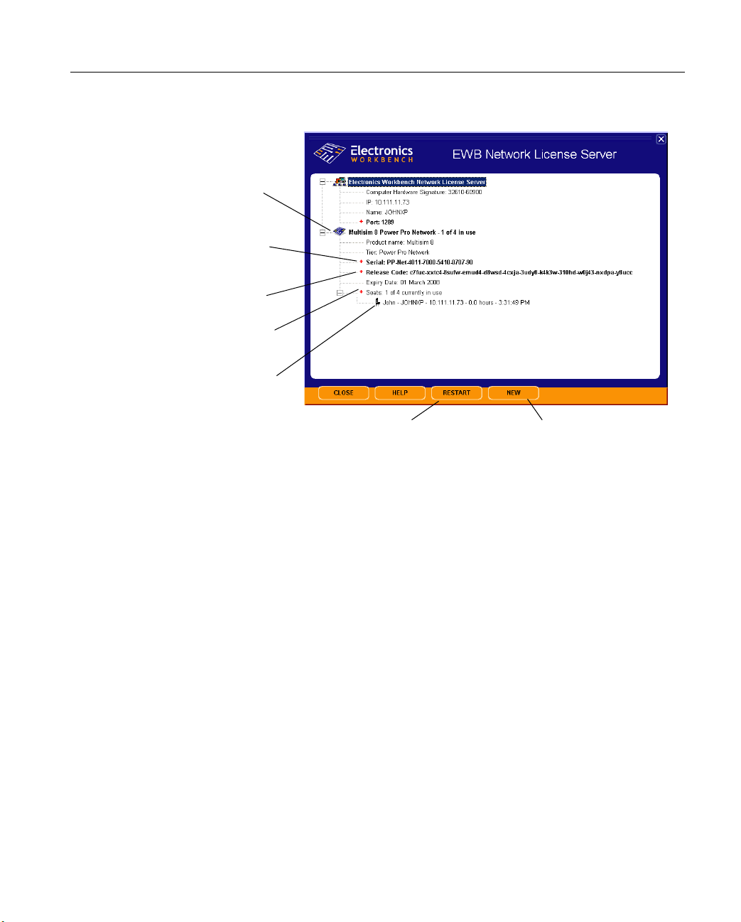
Network License Server
7. When network seats are being used, the dialog will appear similar to the following:
Right-click to edit
release codes, edit
serial numbers or
remove the
product
Right-click to edit
serial number
Right-click to edit
release code
Right-click to
log-off all users
Right-click on
individual users to
log them off
Click to restart the Network License Server software.
1.4.2 Administering Fixed Seat Licenses
This section gives additional information needed for the administration of Fixed Seat
Licenses.
To add (authorize) a seat signature:
1. Go to the computer that contains the client software that you wish to add (for example,
Multisim) and launch the software. As this software is not yet authorized, a message
displays indicating that the computer’s signature was not recognized by the server. Copy
down the signature indicated in the message.
2. From NLS, right-click on
from the pop-up that displays.
3. When prompted, enter the signature that you copied down from the client computer and
OK.
click
Authorized Seat Signatures and select Authorize a new computer
Click to add a new product.
Multicap 9 User Guide 1-11
Page 29

Installing Multicap
Authorized and Available Seats
Number of seats logged in
Number of Authorized Seats
Maximum Seats Available
1.4.3 Reviewing License Server Events
The Network License Server records all client connections or attempted connections in the
system event log. To access the event log, go to the
Administrative Tools, and then select Event Viewer.
In the left-hand pane of the
EWBNLSS are from the
detail.
Event Viewer, choose Application Log. All events with the source
Network License Server. Double-click on any event to see more
Windows Control Panel, select
1.4.4 Troubleshooting
The following contains solutions to situations that may be encountered with the
Network License Server.
• Network License Server gives “Permission Denied” message.
For security reasons, the
administrator privileges. Attempting to control the license server from a “user” or “power
user” account will cause a permission denied error.
• Client application gives “Connection to the license server failed” message.
Make sure that the server address and port number on the client
dialog have been set correctly. If you have entered a machine name as the server address,
try using the numeric IP address instead. In some networks, this IP address may change
dynamically. Please contact your network administrator for assistance if this occurs
frequently.
1-12 Electronics Workbench
Network License Server may only be run from an account with
Network License Server
Page 30

Network License Server
If either the server machine or client machine has a firewall installed (including the
Windows XP service pack 2 internal firewall), make sure that either:
a) the required port is allowed to be open (in TCP protocol) or
b) the server program (EWBNLSS) or client application is granted an exception.
Please see your firewall’s documentation for more information.
• Client application gives “This product is not registered on the license server”
message.
Make sure that you have used the same product serial number on both the client and the
server.
Make sure that the registration code has been accepted by the license server. No client
application will be licensed until the product has been successfully registered.
• Client application gives “No more instances of the program can be run on the
network” message.
This message is returned when all available license seats have been used up. When a user
shuts down the client application normally, their seat should be released immediately;
however, when a client application terminates unexpectedly (the computer is turned off
while running or there is a fatal error), the license server may take up to five minutes to
relinquish this license for reuse. If you believe that there should be seats available and
clients are being denied licenses, waiting for five minutes to log on is usually sufficient to
allow these seats to be freed.
The administrator may also wish to check the
Network License Server control screen and
try to identify unused but unreleased licenses by their computer name or IP address
subdomain. If the administrator logs off these users, their licenses will be immediately
available for new clients. The administrator may also check for users running multiple
clients on a single machine.
In extreme cases, the administrator may click the
Server
. This will immediately release all licenses and then reissue them silently to active
Restart button on the Network License
authorized users only. For most client users, this will be an invisible process. This option
should however be used with caution: if the number of clients requesting licenses is
indeed over the seat limit, the license server cannot guarantee that exactly the same set of
clients will be granted licenses as had them before the reset operation. Therefore, some
authorized clients may be given the “no more instances of the program can be run on the
network” message in the middle of their active session and be prohibited from continuing
their work (however, they will be given the opportunity to save their work).
Multicap 9 User Guide 1-13
Page 31

Installing Multicap
1.5 Support and Upgrade
The Support and Upgrade program lets you call Electronics Workbench with your technical
questions. The program also entitles you to no-charge upgrades to the software as new
versions are released.
Between major upgrade releases, Electronics W orkbench puts out a series of patches that may
add incremental functionality, add new parts to the database, or quickly address any issues
found in the field.
If you allow it to (a choice you initially make upon install and can later change), Multisim or
Ultiboard will quickly and silently check the Electronics Workbench website for the
availability of new patches and upgrades when you start the application. If any are available,
it will open the Support and Upgrade Utility (SUU) program that will allow you to download
and install all the necessary patches to get you to the most current version of your product.
1.5.1 Checking for Updates
Unless you selected I will check for updates and messages manually during the installation of
your software (e.g., Multisim, Ultiboard), SUU checks for updates when you launch that
software. You can also check for updates at any time by following the procedure below.
To check for updates:
1. Select
2. If updates are available, it is indicated in the
Note A message advising that your software is up-to-date appears if there are no updates
3. Proceed to “1.5.2 Installing Updates” on page 1-14.
Help/Check for Updates. SUU launches and checks for updates.
click on the
available.
Release Notes link for a description of the upgrade.
Support and Upgrade Utility window. You can
1.5.2 Installing Updates
Use the procedure below to install updates. To determine if updates are available, see “1.5.1
Checking for Updates” on page 1-14.
Most users will install all available upgrades. You can also upgrade to a specific version. This
option should only be used to ensure parallel versions of software are being run within an
organization or institution.
1-14 Electronics Workbench
Page 32

Support and Upgrade
Installing all Updates
To install all available updates:
1. From the
Patch information appears as the download progresses. When all downloads have been
made the install process begins.
2. Follow the onscreen prompts (if available) to complete the upgrade.
Note Some patches may be configured to install without user input.
Support and Upgrade Utility, click on Upgrade to Latest Version.
Upgrading to a Specific Version
To upgrade to a specific version:
1. From the
2. Click on a button in the
3. Click
Patch information appears as the download progresses.When all downloads have been
made the install process begins.
4. Follow the onscreen prompts to complete the upgrade.
Support and Upgrade Utility, click on Advanced Options.
Upgrade to Specific Version column.
Yes when prompted to confirm the upgrade.
1.5.3 Viewing Messages
To view messages:
1. Select
2. Click on
3. You can also click on
Help/Check for Updates. SUU launches and checks for updates.
(For instructions on what to do if there are available updates, see “1.5.2 Installing
Updates” on page 1-14).
more info... in the Messages area, beside the message of interest. The full message
appears.
Message History to display a history of received messages.
1.5.4 Changing Settings
The initial settings for SUU are done during Multicap’s installation procedure. If you would
like to change these settings, follow the procedure outlined below.
To change the Support and Upgrade Utility’s settings:
1. Select
Multicap 9 User Guide 1-15
Help/Check for Updates. SUU launches and checks for updates.
Page 33

Installing Multicap
(For instructions on what to do if there are available updates, see “1.5.1 Checking for
Updates” on page 1-14).
2. Click on the
Note The
by this setting.
3. Select the desired options and click
Settings button.
Language field applies to messages only. The sofware’s language is not affected
OK.
1.6 Uninstalling Multicap 9
1.6.1 Uninstalling the Single User Version
1. Ensure that you have recorded the serial number before uninstalling the software.
2. Click the Windows
3. Click
4. Click
5. From the
Control Panel.
Add or Remove Programs. The Add or Remove Programs dialog appears.
list, select Multicap 9 and select Remove. Multicap 9 will be removed from your
computer.
Start button.
1.7 Uninstalling SUU
To uninstall SUU:
1. Click the Windows
2. Click
3. Click
4. From the
1-16 Electronics Workbench
Control Panel.
Add or Remove Programs. The Add or Remove Programs dialog appears.
list, select EWB Support and Upgrade Utility and select Remove. SUU will be
removed from the standalone workstation.
Start button.
Page 34

Uninstalling a Site Version
1.8 Uninstalling a Site Version
1.8.1 Uninstalling Standalone Multi-Station Installation
At each standalone workstation, perform the following procedure:
1. Ensure you have recorded the serial number.
2. Click the Windows
3. Click
4. Click
5. From the
Control Panel.
Add or Remove Programs. The Add or Remove Programs dialog appears.
list, select Multicap 9 and select Remove. Multicap 9 will be removed from the
standalone workstation.
1.8.2 Uninstalling Network Installation
Only the workstation that was used to install Multicap 9 to the network directory (host
computer) can be used to remove it. Performing the steps below on other workstations (client
computer) will only remove the Multicap 9 folder.
Start button.
To uninstall Multicap 9 from the network directory or the Multicap 9 folder:
1. Ensure that you have recorded the serial number prior to uninstalling Multicap 9.
2. Click the Windows
3. Click
4. Click
5. From the
Control Panel.
Add or Remove Programs. The Add or Remove Programs dialog appears.
list, select Multicap 9 and select Remove. If the workstation is the host computer ,
Multicap 9 is removed from the network directory. If the workstation is only a client
computer, the Multicap 9 folder is removed.
Start button.
1.8.3 Uninstalling Combination Standalone Multi-Station and Network Installations
Follow the instructions in “1.8.1 Uninstalling Standalone Multi-Station Installation” on
page 1-17 and “1.8.2 Uninstalling Network Installation” on page 1-17, as necessary.
Multicap 9 User Guide 1-17
Page 35

Installing Multicap
1.9 Uninstalling NLS
To uninstall NLS:
1. Click the Windows
2. Click
3. Click
4. From the
Control Panel.
Add or Remove Programs. The Add or Remove Programs dialog appears.
list, select EWB Network License Server and select Remove. SUU will be
removed from the standalone workstation.
Start button.
1-18 Electronics Workbench
Page 36

Chapter 2
Multicap Tutorial
This chapter contains a tutorial that introduces you to Multicap.
Some of the features described in this chapter may not be available in your edition of
Multicap 9. Such features have an icon in the column next to their description. Refer to the
release notes for a list of the features in your edition.
The following are described in this chapter.
Subject Page No.
The Electronics Workbench Suite 2-1
Multicap 9 Tutorial
Schematic Capture
2-2
2-3
2.1 The Electronics Workbench Suite
Electronics Workbench provides a suite of EDA (Electronics Design Automation) tools that
assist you in carrying out the major steps in the circuit design flow. The suite consists of the
following major components:
Multicap is a schematic capture program suitable for pure schematic entry, driving simulation,
and feeding to downstage steps, such as PCB layout. Multisim includes all of Multicap and
adds mixed analog/digital simulation capability. MultiVHDL adds HDL model creation and
Multicap 9 User Guide 2-1
Page 37

Multicap Tutorial
co-simulation to Multisim. Depending on your tier of Multisim, optional add-ons may be
available, such as for RF simulation and extended parts libraries.
Ultiboard, fed from Multicap or Multisim, is used to design printed circuit boards, perform
certain basic mechanical CAD operations, and prepare them for manufacturing. Ultiroute is
an add-on to Ultiboard that provides automated parts placement and layout beyond what is
available in Ultiboard stand-alone.
All of the products in the Electronics Workbench suite are available in multiple tiers
depending upon budget and needs.
2.2 Multicap 9 Tutorial
This tutorial leads you through the schematic capture process. After following the steps
outlined on the following pages, you will have designed a circuit that will, when built, sample
a small analog signal, amplify it and then count the occurrences of the signal on a simple
digital counter.
Helpful tips are indicated by the presence of an icon in the left column, as in:
You can access the online help at any time by pressing F1 on your keyboard, or by clicking on
Help button in a dialog box.
the
When you get to the wiring section of this tutorial, you can carry on with the circuit you
created in the component placement section, or open the file "Tut1.ms8" (which has all
components properly placed) from the Tutorial folder (found inside the Samples folder) and
proceed.
2-2 Electronics Workbench
Page 38

2.2.1 Schematic Capture
In this section, you will place and wire the components in the circuit shown below.
Multicap 9 Tutorial
Opening and Saving the File
When you first launch Multicap, a blank file is opened on the workspace called "Circuit1".
To save the file with a new name:
1. Select
2. Navigate to the location where you wish the file to reside, and enter "sample_and_count"
To guard against accidental loss of data, set up a timed auto-backup of the file in the
of the
To open an existing file:
1. Select
Multicap 9 User Guide 2-3
File/Save As to display a standard Windows Save dialog.
as the filename, and click on the
Preferences dialog box.
File/Open, navigate to the location where the file resides, highlight the file, and
click on the
Open button.
Save button.
Save tab
Page 39

Multicap Tutorial
Y ou can import legacy OrCAD® or PSpice® files by selecting the desired type that appears in
the "Files of Type" drop-down list of the Windows Open dialog.
To view files from earlier versions of Multicap, select the desired version in the
drop-down in the
Open dialog.
Files of Type
Placing the Components
1. Open sample_and_count.ms9 as described above.
2. Select
Place/Component to display the Select a Component browser, navigate to the
7-segment LED display as shown below and click
OK. The component appears as a
"ghost" on the cursor.
Once you have selected the desired
As you type, the string appears in the
Group and Family, start typing the component's name.
Searching field at the bottom of the browser. In the
above example, type SEVEN_SEG_DECIMAL_COM_A_BLUE. Matches are displayed
as you type.
3. Move the cursor to the top-right of the workspace and left-click to place the component.
Note that the Reference Designator for this component is "U1".
2-4 Electronics Workbench
Page 40

Multicap 9 Tutorial
4. Place the remaining components in the Digital Counter area as shown below.
While placing the 200-ohm resistor, rotate it to a vertical orientation by pressing C
TRL-R on
your keyboard.
Reference Designators (e.g., U1, U2) are assigned in the order the components are placed. If
you place components in a different order than in the original circuit, the numbering will
differ. This will not effect the operation of the circuit in any way.
5. Place the parts in the Counter Control section. After placement, right-click on each of the
SPDT switches and select
Flip Horizontal.
The SPDT switches are in the
Basic Group; Switch Family
When a part is on the workspace and you want to place the same part again, highlight it and
Edit/Copy, then Edit/Paste .
select
Multicap 9 User Guide 2-5
Page 41

Multicap Tutorial
6. Place the parts in the Analog Amplifier section as shown below, rotating as needed.
After you place the AC voltage signal source, double-click on it. Change the
to 0.2 V and click
OK to close the dialog.
Voltage (Pk)
7. Place the parts in the Bypass Capacitors section as shown below.
8. Place the header and associated parts as shown below.
J3 is in the Basic Group;
Connectors Family
Once you have wired a circuit, you can drop two-pinned passive components like resistors
directly onto a wire. The connection is automatically made by Multicap.
Wiring the Circuit
Multicap is modeless; there are no wiring or part placement modes to toggle between. All
components have pins that you use to wire them to other components or instruments. As soon
as your cursor is over a pin, Multicap knows you want to wire and the pointer changes to a
crosshair.
2-6 Electronics Workbench
Page 42

Multicap 9 Tutorial
You can wire the circuit that you placed on the workspace or you can use “Tut1.ms9” from the
Tutorial folder (found inside the Samples folder).
To wire the circuit:
1. Click on a pin on a component to start the connection (your pointer turns into a crosshair)
and move the mouse. A wire appears, attached to your cursor.
2. Click on a pin on the second component to finish the connection. Multicap automatically
places the wire, which conveniently snaps to an appropriate configuration, as shown
below. This feature saves a great deal of time when wiring large circuits.
3. You can also control the flow of the wire by clicking on points as you move the mouse.
Each click "fixes" the wire to that point.
4. Finish wiring the Digital Counter section as shown below.
Multicap 9 User Guide 2-7
Page 43

Multicap Tutorial
5. Wire the Counter Control section as shown below. Select
Place/Junction to place a junction
beside J1. Repeat for J2 and wire the junctions to each switch as shown.
V irtual Wiring - To avoid clutter, this circuit uses virtual connections between the Counter
Control and Digital Counter sections. A virtual connection is achieved when two
unconnected wires are given the same net name. (A net represents a group of pins wired
together at the same electrical point).
If the net names are not showing, select
the
Sheet Properties dialog box that appears. Select Show All in the Net Names area.
Options/Sheet Properties and click on the Circuit tab in
6. Change the net name of the wire to the right of J1, by double-clicking on the wire and
entering "ENABLE" in the
Net Name field of the Net dialog that appears.
7. Change the net name of the wire to the right of J2 to "LOAD".
8. Place and wire junctions to U2 as shown below. Then rename the nets to "ENABLE" and
"LOAD". When prompted that nets already exist with these names, click
Yes to continue.
2-8 Electronics Workbench
Page 44

Multicap 9 Tutorial
9. Finish wiring the circuit as shown below.
Reports
Multicap allows you to generate a number of reports: Bill of Materials (BOM), Component
Detail Report, Netlist Report, Schematic Statistics, Spare Gates and the Cross Reference
Report. This section uses the
BOM as an example for the tutorial circuit.
A bill of materials lists the components used in your design and therefore provides a summary
of the components needed to manufacture the circuit board. Information provided in the
Bill of Materials includes:
• quantity of each component needed
• description, including the type of part (example: resistor) and value (examples: 5.1 kohm)
• Reference Designator of each component
• package or footprint of each component
Multicap 9 User Guide 2-9
Page 45

Multicap Tutorial
To create a
1. Click the
BOM for your circuit:
Reports menu and choose Bill of Materials from the menu that appears.
2. The report appears, looking similar to this:
T o print the
Bill of Materials, click the Print button. A standard Windows print screen appears,
allowing you to choose the printer, number of copies, and so on.
To save the
Bill of Materials to a file, click the Save button. A standard Windows file save
dialog box appears, allowing you to specify the path and file name.
Because the
Bill of Materials is primarily intended to assist in procurement and manufacturing,
it includes only “real” parts. That is, it excludes parts that are not real or able to be purchased,
such as sources or virtual components.
To see a list of components in your circuit that are not “real” components, click the
Virtual
button. A separate window appears, showing these components only.
Detailed information on this and other reports can be found in Chapter 9, “Reports”.
2-10 Electronics Workbench
Page 46

Chapter 3
User Interface
This chapter explains the basic operation of the Multicap 9 user interface.
Some of the features described in this chapter may not be available in your edition of
Multicap 9. Such features have an icon in the column next to their description. Refer to the
release notes for a list of the features in your edition.
The following are described in this chapter.
Subject Page No.
Introduction to the Multicap Interface 3-3
Toolbars
Standard Toolbar
Main Toolbar
View Toolbar
Components Toolbar
Virtual Toolbar
Graphic Annotation Toolbar
Using the Pop-up Menus
Pop-up From Circuit Window, with no Component Selected
Pop-up From a Selected Component
Pop-up From a Selected Wire
Pop-up From a Selected Text Block or Graphic
Pop-up From a Title Block
Pop-up from a Comment
3-4
3-5
3-6
3-7
3-8
3-9
3-10
3-10
3-11
3-13
3-15
3-15
3-16
3-17
Multicap 9 User Guide 3-1
Page 47

User Interface
Subject Page No.
Setting Schematic Capture Preferences
Using the Preferences Dialog Box
Using the Sheet Properties Dialog Box
Design Toolbox
Visibility Tab
Hierarchy Tab
Customizing the Interface
Commands tab
To olbars tab
Keyboard tab
Menu tab
Options tab
Customization Pop-up Menus
Other Customization Options
3-18
3-18
3-23
3-32
3-32
3-33
3-35
3-36
3-37
3-38
3-39
3-40
3-40
3-41
3-2 Electronics Workbench
Page 48

Introduction to the Multicap Interface
3.1 Introduction to the Multicap Interface
Multicap’s user interface consists of the following basic elements:
Standard toolbar
Component
toolbar
Design Toolbox
Main toolbar
Graphic Annotation
toolbar
Menu Bar
“In Use” list
View toolbar
Status bar
Active circuit tab
Spreadsheet view
Circuit
window
Scroll left/right
Menus are where you find commands for all functions. For details, see “A.1 Multicap Menus”
on page A-1.
Multicap 9 User Guide 3-3
Page 49

User Interface
Standard toolbar contains buttons for commonly-performed functions, as described in
The
“3.2.1 Standard Toolbar” on page 3-5.
Component toolbar contains buttons that let you select components from the Multicap
The
databases for placement in your schematic. See “3.2.4 Components Toolbar” on page 3-8.
Circuit Window (or workspace) is where you build your circuit designs.
The
Status Bar displays useful information about the current operation and a description of the
The
item the cursor is currently pointing to.
Design Toolbox lets you navigate through the different types of files in a project
The
(schematics, PCBs, reports), view a schematic’s hierarchy and show or hide different layers.
For details, see “3.5 Design Toolbox” on page 3-32.
Spreadsheet View allows fast advanced viewing and editing of parameters including
The
component details such as footprints, RefDes, attributes and design constraints. Users can
change parameters for some or all components in one step and perform a number of other
functions. For details, see “5.2 The Spreadsheet View” on page 5-7.
3.2 Toolbars
The toolbars listed below are available in Multicap:
• Standard Toolbar
• Main Toolbar
• View Toolbar
• Components Toolbar
• Virtual Toolbar
• Graphic Annotation Toolbar
Note If the above toolbars are not visible, select
Note For a description of the menus and commands found in Multicap, refer to “A.1
Multicap Menus” on page A-1.
View/Toolbars/<toolbar name>.
3-4 Electronics Workbench
Page 50

3.2.1 Standard Toolbar
The Standard toolbar contains buttons for commonly performed functions.
Toolbars
The buttons in the
Button Description
Standard toolbar are described below:
New button. Creates a new circuit file.
Open button. Opens an existing circuit file.
Save button. Saves the active circuit.
Print Circuit button. Prints the active circuit.
Print Preview button. Previews the circuit as it will be printed.
Cut button. Removes the selected elements and places them on the
Windows clipboard.
Copy button. Copies the selected elements and places them on the Windows
clipboard.
Paste button. Inserts the contents of the Windows clipboard at the cursor
location.
Multicap 9 User Guide 3-5
Page 51

User Interface
3.2.2 Main Toolbar
The buttons in the Main toolbar are described below:
Button Description
Toggle Design Toolbox button. Switches the Design Toolbox on and of f. For
details, see “3.5 Design Toolbox” on page 3-32.
Toggle Spreadsheet View button. Switches the Spreadsheet View on and
off. For details, see “5.2 The Spreadsheet View” on page 5-7. This feature is
not available in all versions of Multicap.
Database Manager button. Launches the Database Manager dialog box.
For details, see “8.3 Editing Components” on page 8-10.
Create Component button. Launches the Component Wizard. For details,
see “8.2 Adding Components with the Component Wizard” on page 8-3.
Electrical Rules Checking button. Checks that the electrical rules
established for the wiring of the circuit have been followed. For details, see
“5.4 Electrical Rules Checking” on page 5-32.
Back Annotate from Ultiboard button. For details, see “10.3 Back
Annotation” on page 10-4.
Forward Annotate button. For details, see “10.2 Forward Annotation” on
page 10-4.
In Use List (not shown here). Click on the arrow to display a list of the active
circuit’s components. For details, see “4.4.3 Using the In Use List” on
page 4-13.
Help button. Launches the help file.
3-6 Electronics Workbench
Page 52

3.2.3 View Toolbar
The buttons in the View toolbar are described below:
Button Description
Toggle Full Screen button. Displays only the workspace, with no toobars or
menu items.
Increase Zoom button. Magnifies the active circuit.
Decrease Zoom button. Decreases the magnification of the active circuit.
Zoom Area button. Drag the cursor to select an area on the workspace to
magnify.
Toolbars
Zoom Fit to Page button. Shows the entire circuit in the workspace.
Multicap 9 User Guide 3-7
Page 53

User Interface
3.2.4 Components Toolbar
The buttons in the Component toolbar are described below. Each button will launch the place
component browser (
pre-selected. For details, see “4.4.1 Using the place component browser” on page 4-4.
Button Description
Select a Component browser) with the group specified on the button
Source button. Selects the Source components group in the browser.
Basic button. Selects the Basic components group in the browser.
Diode button. Selects the Diode components group in the browser.
Transistor button. Selects the Transistor components group in the browser.
Analog button. Selects the Analog components group in the browser.
TTL button. Selects the TTL components group in the browser.
CMOS button. Selects the CMOS component group in the browser.
Miscellaneous Digital button. Selects the Miscellaneous Digital component
group in the browser.
Mixed button. Selects the Mixed component group in the browser.
Indicator button. Selects the Indicator component group in the browser.
Miscellaneous button. Selects the Miscellaneous component group in the
browser.
3-8 Electronics Workbench
Page 54

Button Description
Electromechanical button. Selects the Electromechanical component group
in the browser.
RF button. Selects the RF component group in the browser.
Place Hierarchical Block button. Opens a file to be embedded as a
hierarchical block.
Place Bus button. For details, see “6.4 Buses” on page 6-16.
3.2.5 Virtual Toolbar
Use the Virtual toolbar to place virtual components on your workspace.
Toolbars
The buttons in the
Virtual toolbar are described in “4.4.2 Placing Virtual Components” on
page 4-9.
Multicap 9 User Guide 3-9
Page 55

User Interface
3.2.6 Graphic Annotation Toolbar
The buttons in the Graphic Annotation toolbar are described below. For details on their use,
see “4.9.6 Graphic Annotation” on page 4-43.
Button Description
Place Text button. Places a text frame on your workspace into which you can
enter miscellaneous text. For details, see “4.9.4 Adding Miscellaneous Text”
on page 4-39.
Line button. Click on this button to draw a line.
Multiline button. Click on this button to draw a multiline.
Rectangle button. Click on this button to draw a rectangle.
Ellipse button. Click on this button to draw an ellipse.
Arc button. Click on this button to draw an arc.
Polygon button. Click on this button to draw a polygon.
Picture button. Click on this button to place a picture on the workspace.
Place Comment button. Click on this button to place a comment on the
workspace. For details, see “4.9.5 Adding a Comment” on page 4-40.
3.3 Using the Pop-up Menus
In addition to the standard menus at the top of the screen (File, Edit, etc.), there are also a
number of context-sensitive pop-up menus available.
3-10 Electronics Workbench
Page 56

Using the Pop-up Menus
3.3.1 Pop-up From Circuit Window , with no Component Selected
If you right-click on the circuit window with no component selected, a pop-up menu of
appropriate commands appears. These commands are:
Command Description
Place Component Lets you browse the databases (“Master”, “Corporate” and “User”) for
Place Schematic Component
Place Schematic - Junction Places a connector. For details, see “4.6 Manually Adding a Junction
Place Schematic - Wire Use to place a wire on the workspace. For details, see “4.5.5 Placing
Place Schematic - Bus Places a bus with segments created as you click. For details, see “6.4
Place Schematic HB/SC Connector
Place Schematic Off-Page Connector
Place Schematic Bus HB/SC Connector
Place Schematic Bus Off-Page Connector
Place Schematic Hierarchical Block from File
components to be placed. For details, see “4.4.1 Using the place
component browser” on page 4-4.
Lets you browse the databases (“Master”, “Corporate” and “User”) for
components to be placed. For details, see “4.4.1 Using the place
component browser” on page 4-4.
(Connector)” on page 4-29.
Wires Directly Onto Workspace” on page 4-26.
Buses” on page 6-16.
Adds connectors to a circuit for use in a hierarchical block or a
subcircuit.
Places an off-page connector on your workspace. For details, see “6.1
Flat Multi-sheet Design” on page 6-2.
Adds bus connectors to a circuit for use in a hierarchical block or a
subcircuit.
Places an off-page connector for use with buses only on your
workspace.
Opens a file to be embedded as a hierarchical block. For details, see
“6.2.5.1 Placing a HB from an Existing File” on page 6-8.
Place Schematic New Hierarchical Block
Place Schematic - Replace
by Hierarchical Block
Place Schematic New Subcircuit
Displays the Hierarchical Block Properties dialog box. For details, see
“6.2.5 Adding a Hierarchical Block” on page 6-7.
Replaces the selection by a hierarchical block.
Places a new subcircuit on the workspace. For details, see “6.2.6
Adding a Subcircuit” on page 6-9.
Multicap 9 User Guide 3-11
Page 57

User Interface
Command Description
Place Schematic Replace by Subcircuit
Place Schematic Multi-Page
Place Schematic Merge Bus
Place Schematic Bus Vector Connect
Place Graphic - Text Lets you place text on the circuit. For details, see “4.9.4 Adding
Place Graphic - Line Places a straight line on your workspace. For details, see “4.9.6
Place Graphic - Multiline Places a multiline on your workspace. For details, see “4.9.6 Graphic
Place Graphic - Rectangle Places a rectangle on your workspace. For details, see “4.9.6 Graphic
Place Graphic - Ellipse Places an ellipse on your workspace. For details, see “4.9.6 Graphic
Place Graphic - Arc Places an arc on your workspace. For details, see “4.9.6 Graphic
Replaces the selection by a subcircuit.
Opens a new flat page. For details, see “6.1 Flat Multi-sheet Design”
on page 6-2
Merges selected buses.
Use to place numerous connections from a multi-pinned device, such
as an IC, to a bus. For details, see “6.4.5 Bus Vector Connect” on
page 6-27.
Miscellaneous Text” on page 4-39.
Graphic Annotation” on page 4-43.
Annotation” on page 4-43.
Annotation” on page 4-43.
Annotation” on page 4-43.
Annotation” on page 4-43.
.
Place Graphic - Polygon Places a polygon on your workspace. For details, see “4.9.6 Graphic
Place Graphic - Picture Places a picture on your workspace. For details, see “4.9.6 Graphic
Place Comment Use to “pin” a comment to the workspace, or directly to a component.
Cut Removes the selected item from the circuit and places it on the
Copy Copies the selected item from the circuit to the clipboard.
Paste Pastes the current contents of the clipboard onto your circuit.
Delete Deletes the selection from the workspace.
Select All Selects all elements on the workspace.
Annotation” on page 4-43.
Annotation” on page 4-43.
For details, see “4.9.5 Adding a Comment” on page 4-40.
clipboard.
3-12 Electronics Workbench
Page 58

Command Description
Using the Pop-up Menus
Paste as Subcircuit Pastes the contents of the clipboard onto the workspace as a
Replace by HB Replaces the elements that you have selected with a hierarchical
Replace by SC Replaces the elements that you have selected with a subcircuit. See
Font Displays a dialog box where you set font information for the circuit. For
Properties Displays the Sheet Properties dialog box. Be sure that you have no
subcircuit.
block. See “6.2.5.2 Replacing Components with an HB” on page 6-9.
“6.2 Hierarchical Design” on page 6-3.
details, see “3.4.2.4 Sheet Properties - Font Tab” on page 3-28.
elements on the workspace selected, or the properties for that element
will appear instead. For details, see “3.4.2 Using the Sheet Properties
Dialog Box” on page 3-23.
3.3.2 Pop-up From a Selected Component
If you right-click on a selected element , a pop-up menu of appropriate commands appears.
These commands are:
Command Description
Cut Removes the selected components, circuits or
Copy Copies the selected components, circuits or
text, and places them on the clipboard.
text, and places them on the clipboard. For
details, see “4.4.6 Copying a Placed
Component” on page 4-16.
Paste Places the contents of the clipboard to the
Delete Deletes the selection from the workspace.
Flip Horizontal Flips the selection horizontally. For details, see
Flip Vertical Flips the selection vertically. For details, see
workspace. The cursor shows a “ghosted”
image of the item to be pasted. Click to indicate
where the item is to be pasted.
“4.7 Rotating/Flipping Placed Components” on
page 4-30.
“4.7 Rotating/Flipping Placed Components” on
page 4-30.
Multicap 9 User Guide 3-13
Page 59

User Interface
90 Clockwise Rotates the selection 90 degrees clockwise.
For details, see “4.7 Rotating/Flipping Placed
Components” on page 4-30.
90 CounterCW Rotates the selection 90 degrees
counterclockwise. For details, see “4.7
Rotating/Flipping Placed Components” on
page 4-30.
Bus Vector Connect Displays the Bus Vector Connect dialog box.
For details, see “6.4.5 Bus Vector Connect” on
page 6-27.
Replace by HB Replaces the elements that you have selected
Replace by SC Replaces the elements that you have selected
Replace Components Invokes the Select a Component browser from
Edit Symbol You can edit either the appearance of the
Color Displays a color palette where you can change
Font Changes the font of various elements on the
Properties If a component is selected, displays that
with a hierarchical block. See “6.2.5.2
Replacing Components with an HB” on
page 6-9.
with a subcircuit. See “6.2 Hierarchical Design”
on page 6-3.
which you can select a new component. See
also, “4.4.7 Replacing a Placed Component” on
page 4-17.
symbol on the workspace (In-place Edit Mode).
For details, see “8.5.2 Creating and Editing a
Component’s Symbol with the Symbol Editor”
on page 8-15.
the color of the selected element’s lines.
workspace from their default values. For
details, see “3.4.2.4 Sheet Properties - Font
Tab” on page 3-28.
component’s properties dialog box. If an
instrument is selected, opens the instrument
face.
3-14 Electronics Workbench
Page 60

3.3.3 Pop-up From a Selected Wire
If you right-click on a selected wire on the circuit window, a pop-up menu of appropriate
commands appears. These commands are:
Command Description
Delete Deletes the selected wire from the workspace.
Wire Color Changes the color of the selected wire from its default value.
Using the Pop-up Menus
Segment Color Changes the color of the selected wire segment from its
Font Changes the font of various elements on the worksp ace from
Properties Displays the Net dialog box. “4.9.2 Modifying Net Names” on
default value.
their default values. For details, see “3.4.2.4 Sheet
Properties - Font Tab” on page 3-28.
page 4-35.
3.3.4 Pop-up From a Selected Text Block or Graphic
If you right-click on a selected text block or graphic element in the circuit window, a pop-up
menu of appropriate commands appears. These commands are:
Command Description
Delete Deletes the selected item.
Flip Horizontal Flips the selection horizontally. For details, see “4.7 Rotating/
Flipping Placed Components” on page 4-30.
Flip Vertical Flips the selection vertically. For details, see “4.7 Rotating/
90 Clockwise Rotates the selection 90 degrees clockwise. For details, see
Flipping Placed Components” on page 4-30.
“4.7 Rotating/Flipping Placed Components” on page 4-30.
90 CounterCW Rotates the selection 90 degrees counterclockwise. For
details, see “4.7 Rotating/Flipping Placed Components” on
page 4-30.
Pen Color Changes the color of the selected item from its default value.
Multicap 9 User Guide 3-15
Page 61

User Interface
Command Description
Pen Style Changes the style of the pen for a selected graphic. Is
Fill Color Changes the color of the fill for selected rectangles, ellipses
Fill Type Changes the appearance of the fill for selected rectangles,
Arrow Places an arrow on selected lines and multilines. Is disabled
Order Use to Bring to Front or Send to Back selected element.
Assign to Layer Places selected element on the selected layer. Deselect to
Font Lets you select a font, font style and size for selected text.
Properties Is inactive for text blocks or graphics.
disabled if text is selected.
and polygons. Is disabled if any other graphic element, or
text is selected.
ellipses and polygons. Is disabled if any other graphic
element, or text is selected.
if any other graphic element, or text is selected.
remove an element from the assigned layer. See “3.4.2.6
Sheet Properties - Visibility Tab” on page 3-31.
3.3.5 Pop-up From a Title Block
If you right-click on a selected title block in the circuit window, a pop-up menu of appropriate
commands appears. These commands are:
Command Description
Delete Deletes the selected title block.
Edit Title Block Launches the Title Block Editor. For details, see “5.3 Title
Color Displays a palette where you can change the selection’s
Move to - Bottom Left Places the selected title block at the bottom left corner of the
Move to - Bottom Right Places the selected title block at the bottom right corner of
Block Editor” on page 5-13. (To edit the selected title block,
select Edit Symbol/Title Block).
color.
document.
the document.
3-16 Electronics Workbench
Page 62

Command Description
Using the Pop-up Menus
Move to - Top Left Places the selected title block at the top left corner of the
Move to - Top Right Places the selected title block at the top right corner of the
Properties Lets you change the information that you see in the title
document.
document.
block. For details, see “4.9.3.1 Entering the Title Block
Contents” on page 4-37.
3.3.6 Pop-up from a Comment
If you right-click on a selected wire on a selected Comment, a pop-up menu of appropriate
commands appears. These commands are:
Command Description
Cut Removes the selected item and places it on the clipboard.
Copy Copies the selected item and places it on the clipboard.
Paste Places the contents of the clipboard to the workspace. The
cursor shows a “ghosted” image of the item to be pasted.
Click to indicate where the item is to be pasted.
Delete Deletes the selected item from the workspace.
Show Comment Displays the contents of the comment.
Edit Comment Is active for a selected comment only. Use to enter text into
the comment.
Font Changes the font of various elements on the worksp ace from
Properties Depending on the element selected, displays either the
their default values. For details, see “3.4.2.4 Sheet
Properties - Font Tab” on page 3-28.
Comment Properties, or the Probe Properties dialog box.
See “4.9.5 Adding a Comment” on page 4-40 or “10.15.1.1
Measurement Probe Settings (rfe)” on page 10-49.
Multicap 9 User Guide 3-17
Page 63

User Interface
3.4 Setting Schematic Capture Preferences
You can customize virtually any aspect of Multicap preferences, including the colors used in
your circuit, page size, zoom level, auto-backup interval, symbol set (ANSI or DIN) and
printer setup. Your customization settings are saved individually with each circuit file you use
so you could, for example, have one color scheme for one circuit and another for a different
circuit. You can also override the settings for individual instances (for example, change one
particular component from red to orange) or for the entire circuit.
Customization is done through the:
Preferences dialog box — used to set up global preferences. These preferences can vary
•
from computer to computer. See “3.4.1 Using the Preferences Dialog Box” on page 3-18.
Sheet Properties dialog box — used to set up the preferences for the active sheet. These
•
preferences are saved with the circuit files so that if the circuit is opened on another
computer, it will use the same settings. See “3.4.2 Using the Sheet Properties Dialog Box”
on page 3-23
3.4.1 Using the Preferences Dialog Box
This section explains general procedures for setting preferences. The following sections
describe details of setting specific options.
Note For sheet preferences, see “3.4.2 Using the Sheet Properties Dialog Box” on
page 3-23.
To set your user preferences:
1. Choose
following tabs:
2. Select the desired tab.
3. Set the desired customization options. The specific options and settings available in the
tabs are described in the following sections of this chapter.
4. Click
3-18 Electronics Workbench
Options/Global Preferences. The Preferences dialog box appears, offering you the
Paths — where you can change the filepaths for the databases and other items.
•
Save — where you set up Auto-backup timing.
•
Parts — where you set up component placement mode and the symbol standard (ANSI
•
or DIN).
General — where you set up selection rectangle behavior, mouse wheel behavior, bus
•
wiring and auto-wiring behavior.
OK to save your changes.
Page 64

Setting Schematic Capture Preferences
3.4.1.1 Preferences - Paths Tab
The Multicap installation puts specific files in specific locations. If necessary you can point
Multicap to a new location to find, for example, database files. You can also use this dialog
box to create and specify user settings files that contain individuals' preferences for all
options.
To set up file locations:
1. Choose
2. Select the
Options/Global Preferences. The Preferences dialog box appears.
Paths tab and navigate to the appropriate locations for the different elements:
If desired, click to
navigate to a new
location for the files.
Note The most important setting is the
Circuit default path, as this is where all new files are
saved, unless you manually navigate to a new location when saving.
User button images path is where you store any user-created button graphics.
Note
3. To use a different configuration file, navigate to the appropriate user settings file.
4. To create a new user configuration file, click
New user config file from template. You are
prompted to select the configuration file to use as a template, then to enter a name for the
new configuration file.
Multicap 9 User Guide 3-19
Page 65

User Interface
3.4.1.2 Preferences - Save Tab
The options in this tab let you set up auto-backup timing.
Enable to save a security copy
when you do a Save.
Enable auto-backup.
Specify the interval at which
auto-backup will be performed
3-20 Electronics Workbench
Page 66

Setting Schematic Capture Preferences
3.4.1.3 Preferences - Parts Tab
The options in this tab determine where you set up component placement mode, the symbol
standard (ANSI or DIN), phase shift direction and digital simulation settings.
1. In the
Place component mode box, select one of:
Place single component — Allows you to place one selected component at a time.
•
Continuous placement for multi-section part only — Allows you to place multiple
•
sections of a multi-section component. For example, 7400N has four NAND gates, so
using this option means each time you place a 7400N you place a different one of its
NAND gates. Refer to “4.4.1 Using the place component browser” on page 4-4 for an
example of multi-section part placement.
•
Continuous placement — Allows you to place several components of the same type by
continuing to click on the workspace after each component is placed. End continuous
placement by pressing E
Optionally, enable the
the
Select a Component dialog box after you place a component on the workspace. This is
useful when you have many parts to place. (Click E
SC.
Return to Component Browser After Placement checkbox to display
SC when finished part placement).
Multicap 9 User Guide 3-21
Page 67

User Interface
2. In the
Symbol Standard box:
• Select the symbol set to be used for components. The graphic changes to represent the
selected symbol set. To override this setting for individual components, see “8.5.2
Creating and Editing a Component’s Symbol with the Symbol Editor” on page 8-15.
3.4.1.4 Preferences - General Tab
In this tab, you set up selection rectangle behavior, mouse wheel behavior, bus wiring and
auto-wiring behavior.
For details, see “ Showing/
Hiding ‘Move’ Lines” on
page 4-16.
Enable if you wish to delete
wires that are connected to
components being deleted;
to delete wires that are
connected to components
being deleted, leave this box
unchecked.
1. In the
Selection Rectangle box, select either Intersecting or Fully Enclosed. See “ Setting
Dragging Selection Options” on page 4-14 for details.
2. In the
3. In the
Mouse Wheel Behavior box select one of:
Zoom workspace — mouse wheel will let you zoom in and out on workspace.
•
Scroll workspace — mouse wheel will let you scroll up and down the page.
•
Autowire box select the desired options to control the degree of automation used in
wiring. For details, see “4.5.6 Setting Wiring Preferences” on page 4-26.
3-22 Electronics Workbench
Page 68

Setting Schematic Capture Preferences
3.4.2 Using the Sheet Properties Dialog Box
The Sheet Properties dialog box is used to set up the preferences for each sheet. These
preferences are saved with the circuit file so that if the circuit is opened on another computer,
it will use the same settings.
Note For personal (user) preferences, see “3.4.1 Using the Preferences Dialog Box” on
page 3-18.
To set sheet preferences:
1. Select
2. Select the desired tab.
3. Set the desired customization options. The specific options and settings available in the
4. The
5. Click
Options /Sheet Properties.
Or
Right-click on a blank area of the workspace and choose
Properties from the pop-up menu
that appears. Do not select any elements (for example, components, wires) on the
workspace, or the properties dialog box for the selected element will display instead.
Sheet Properties dialog box appears, offering you the following tabs:
The
Circuit — where you set the color scheme and the display properties of workspace text
•
Workspace — where you set the sheet size and properties
•
Wiring — where you set the wire and bus options
•
Font — where you select the font, font size and style for text elements on the circuit
•
PCB — where you set up options for your printed circuit board
•
Visibility — where you enable and disable custom annotation layers.
•
tabs are described in the following sections of this chapter.
Save as Default checkbox is normally enabled. If you do not wish to have the settings
saved as the default, disable this checkbox. Default settings are those used when you
create new circuits (
OK to save your changes. (If you wish to apply the changes without closing the
dialog, click
File/New).
Apply).
Multicap 9 User Guide 3-23
Page 69

User Interface
3.4.2.1 Sheet Properties - Circuit Tab
The options on this tab control the way your circuit and its components appear on the
workspace, and the level of detail which appears. Multicap comes with several color schemes
that affect the circuit window background color, wire color, and component color. You can
also develop your own color scheme to meet your individual needs.
Shows the results of enabling
the options on the right.
Select a built-in color
scheme.
Use to set up a custom color
scheme (buttons are active
only if “Custom” is selected
as scheme).
Shows the currently
selected color scheme.
1. In the
Component box, enable those items you want shown on the workspace. You can
override your choices for a particular component, as described in “5.1.1 Displaying
Identifying Information about a Placed Component” on page 5-2.
Pin names checkbox — when fully checked, shows all pin names; when not checked,
•
shows no pin names; when grey checked, shows pin names for those components
whose default behavior is to show them.
Pin numbers checkbox — when fully checked, shows all pin numbers; when not
•
checked, shows no pin numbers; when grey checked, shows pin numbers for those
components whose default behavior is to show them.
Note Pin names and numbers are made visible as details above; checking and un-checking
Visibility tab of the Design Toolbox has no effect.
in the
3-24 Electronics Workbench
Page 70

Setting Schematic Capture Preferences
2. In the
Net Names box, select how net names will be shown:
Show All — check to display all net names on the workspace.
•
Use Net-specific Setting — check to show net names as set in the Net dialog box. For
•
details, see “4.9.2 Modifying Net Names” on page 4-35.
Hide All — check to hide all net names on the workspace.
•
3. In the
Color box:
• To use one of the built-in color schemes :
- Choose the scheme from the drop-down list.
- A representation of the scheme’s settings appears in the preview box below the list.
• To create a custom color scheme:
- Choose
- Click on the color bar next to any item. A
- Click on the color you want to use for that item and click
- You are returned to the
Custom from the drop-down list.
Color selector dialog box appears.
OK.
Sheet Properties dialog box.
- The results of your choice appear in the preview box.
- Repeat until all your color settings are made.
Multicap 9 User Guide 3-25
Page 71

User Interface
3.4.2.2 Sheet Properties - Workspace Tab
The options on this tab determine the appearance and behavior of the circuit window.
Shows the results of enabling the
options on the right.
Enable those items you want shown.
Modify a sheet size.
Multicap comes with the standard sheet sizes that you can use for capturing your circuit. You
can modify any of the settings of these sizes to make your own custom sheet.
3-26 Electronics Workbench
Page 72

Setting Schematic Capture Preferences
3.4.2.3 Sheet Properties - Wiring Tab
The options on this tab control the wire width, bus width and bus wiring mode options.
Change the wire
width for current or
subsequent wiring.
Set bus wiring mode.
For details, see “6.4
Buses” on page 6-16.
Change the bus
width for current or
subsequent buses.
Multicap 9 User Guide 3-27
Page 73

User Interface
3.4.2.4 Sheet Properties - Font Tab
Use this tab to set the font parameters for all elements in the workspace containing text.
Specify the font, style
and size of labels and
names on your circuit.
Displays a sample
using the selected font
settings.
Specify the text
element to change to
the selected font.
Caution Changing to larger fonts may cause labels to collide or
Changes the font
for all instances of
the elements
selected in
“Change All”.
To change font for
a specific selection,
right-click on the
desired, part, etc,
select Font from
the pop-up that
appears and click
on Selection.
exceed boundaries.
3-28 Electronics Workbench
Page 74

Setting Schematic Capture Preferences
To change the font for any text element of the circuit:
1. Select the font, font style and font size for the desired elements.
2. Select the elements you want to change from the following options in the
section of the tab:
Font Option Description
Change All
Component RefDes The component’s unique identification (Reference Designator). For example,
Component Values
and Labels
Component Attributes Descriptive information you add to specific components using the
Pin Numbers The number automatically assigned to a pin when it is placed on your circuit.
Pin Names The logical name for a pin, for example, GND (for ground).
Net Names The name automatically assigned to a net when it is placed on your circuit.
Schematic Text Notes that you add to your circuit using the Place/Text command. For details
Comments Text found in comments that you add to the circuit from the Place/Comment
Busline Name The name that you assign to buslines. For details, see “6.4 Buses” on
R22.
The value being used by the component and identified in the Values tab of
the component’s properties dialog box. For details on viewing and modifying
this value see “5.1.2 Viewing a Placed Component’s Value” on page 5-3.
The Component label assigned by Multicap and identified in the Label tab of
the component’s properties dialog box. For details on changing this label see
“4.9.1 Modifying Component Labels and Attributes” on page 4-34.
component’s properties dialog box. For details see “4.9.1 Modifying
Component Labels and Attributes” on page 4-34.
For details on changing this name see “4.9.2 Modifying Net Names” on
page 4-35.
see “4.9.4 Adding Miscellaneous Text” on page 4-39.
command. For details, see “4.9.5 Adding a Comment” on page 4-40.
page 6-16.
Multicap 9 User Guide 3-29
Page 75

User Interface
3.4.2.5 Sheet Properties - PCB Tab
This tab is used to set options used when exporting data for PCB layout.
Select this option to
make digital and
analog ground the
same when exporting
to PCB layout
packages.
Select units to use during
export to PCB layout.
As you increase the
number of copper layers,
the number of copper
layers (inner) increases.
This setting is used by
Ultiboard to determine the
default board setup.
3-30 Electronics Workbench
Page 76

Setting Schematic Capture Preferences
3.4.2.6 Sheet Properties - Visibility Tab
This tab lets you add the custom annotation layers that are available in Multicap.
Click to add custom annotation
layers to the schematic. You can
show/hide these layers from the
Visibility tab in the Design
Toolbox. For details, see “3.5.1
Visibility Tab” on page 3-32
For details on annotation layers, refer to “3.5.1 Visibility Tab” on page 3-32.
Multicap 9 User Guide 3-31
Page 77

User Interface
3.5 Design Toolbox
The Design Toolbox is used to manage various elements in the schematic.
Note For a description of the
Control” on page 6-47.
3.5.1 Visibility Tab
The Visibility tab lets you choose which layers to display on the current sheet on the
workspace.
Project View tab, see “6.6 Project Management and Version
Custom annotation layer added
via the Visibility tab in the Sheet
Properties dialog box.
Schematic Capture layers consist of:
The
RefDes — this layer contains the Reference Designators for all elements on the workspace,
•
for example, R1, U2A.
Label and Value — this layer contains the label entered in the component’s properties
•
dialog box in the
example, 1 kohm. See “5.1 Placed Component Properties” on page 5-2 for details.
Attribute and Variant — this layer contains the attribute information entered in the
•
component’s properties dialog box in the
the Variant Status. For details, see “6.5 Variants” on page 6-34.
Net Name — this layer contains the netnames.
•
3-32 Electronics Workbench
Label field in the Label tab. It also contains the component’s value, for
Attributes fields in the Label tab. It also includes
Page 78

Pin Name — this layer contains the pin names, for example, “1Q” in a J-K flip-flop.
•
Pin Number — this layer contains the pin numbers.
•
Bus Entry Label — this layer contains the labels that appear at the point where a wire
•
enters a bus, for example, “Ln 1”.
Fixed Annotations layers consist of:
The
ERC Error Mark — this layer contains the marks that are placed on the schematic that
•
indicate ERC error points. See “5.4 Electrical Rules Checking” on page 5-32 for details.
Comment — this layer contains any comments that you “pin” to the workspace. Refer to
•
“4.9.5 Adding a Comment” on page 4-40 for details.
Text/Graphics — this layer contains any graphic elements that you place on the
•
workspace.
Custom Annotations layers can be added from the Sheet Properties dialog box. For details, see
“3.4.2.6 Sheet Properties - Visibility Tab” on page 3-31.
To hide a layer, disable the layer’s checkbox.
To show a hidden layer, enable the layer’s checkbox.
3.5.2 Hierarchy Tab
The Hierarchy tab contains a tree that shows the files in the design that you have open.
Design Toolbox
Design Root
Active Variant - see “6.5 Variants” on page 6-34
Page 1 of multi-sheet design - see “6.1 Flat Multi-sheet
Design” on page 6-2
Subcircuit - see “6.2 Hierarchical Design” on page 6-3
Hierarchical Block - see “6.2 Hierarchical Design” on page 6-3
Included in Active Variant
Page 2 of multi-sheet design
Multicap 9 User Guide 3-33
Page 79

User Interface
To view context-sensitive menus in the Hierarchy tab:
Pop-up Menus
1. Right-click on an item. Depending on the item, different context-sensitive menus appear.
2. From the Design Root you can select:
Close — to close the entire design.
•
Save — to save the design.
•
3. From an active or in-active variant that branches from the Design Root, you can select:
Set Variant Active — to set the active variant. A blue box displays beside the active
•
variant. For details, see “6.5.2.3 Setting the Active Variant” on page 6-44.
Variant Manager — to display the Variant Manager dialog box. For details, see “6.5.1
•
Setting Up Variants” on page 6-34.
4. From a page of a multi-sheet design (in this example, PowerSupply#1), you can select:
Open Window — to open the page on the workspace.
•
Close Window — to close the page.
•
Rename Page — to change the multi-page’s name.
•
5. From a subcircuit, you can select:
Open Window — to open the subcircuit on the workspace.
•
Close Window — to close the subcircuit.
•
Rename Subcircuit — to change the subcircuit’s name.
•
6. From a Hierarchical Block, you can select:
Open Window — to open the Hierarchical Block on the workspace.
•
Close Window — to close the Hierarchical Block.
•
Map Variants — to display the Hierarchical Block’s properties dialog box, where you
•
can assign its variant status. For details, see “6.5.2.1 Assigning Variant Status to
Components” on page 6-38.
7. From a variant that branches from a Hierarchical Block, you can select:
Variant Manager — to display the Variant Manager dialog box. For details, see “6.5.1
•
Setting Up Variants” on page 6-34.
Exclude from Active Variant — to exclude this variant from the active variant. If
•
desired, you can exclude all variants in a Hierarchical Block from the Active Variant.
Include in Active Variant — to include this variant in the active variant. A blue triangle
•
appears beside the included variant. You can only include one variant at a time in the
Active Variant.
3-34 Electronics Workbench
Page 80

3.6 Customizing the Interface
The Multicap user interface is highly customizable. Separate customizations may be applied
whenever each different type of sheet becomes active. For example, the toolbars and docking
windows may be re-configured as you move from a circuit sheet to a description sheet.
Toolbars may be docked in various positions and orientations. The contents of the toolbars
may be customized. New toolbars may be created. The menu system is fully customizable,
including all pop-up menus for the various object types.
As well, the keyboard shortcut system is customizable. This allows for any keys or key
combinations to be assigned to any command that may be placed in a menu or on a toolbar.
To customize the interface:
1. Select
2. Make changes in the
Options/Customize User Interface.
Customize dialog’s tabs as detailed in the following sections:
•“3.6.1 Commands tab” on page 3-36
•“3.6.2 Toolbars tab” on page 3-37
•“3.6.3 Keyboard tab” on page 3-38
•“3.6.4 Menu tab” on page 3-39
•“3.6.5 Options tab” on page 3-40
•“3.6.6 Customization Pop-up Menus” on page 3-40
•“3.6.7 Other Customization Options” on page 3-41.
Customizing the Interface
Multicap 9 User Guide 3-35
Page 81

User Interface
3.6.1 Commands tab
The Commands tab in the Customize dialog box is used to add commands to menus and
toolbars.
To add a command to a menu or toolbar:
1. Drag it from the
selected in the
2. If you do not see the command that you require, click on another selection in the
Categories list to display more commands.
3. If you wish to add a button to a toolbar that is not showing, click on the
click in the checkbox beside the desired toolbar to make it visible.
4. Click
Close when customizations are complete.
To remove a command from a menu or toolbar, right-click on it and select Delete from the
pop-up that appears. The
Commands list to the desired menu or toolbar. When a command is
Command list, its description is displayed in the Description field.
Customize dialog box must be open when you do this.
Toolbars tab and
To change the position of a command that is in a menu or toolbar, drag it to its new location.
The
Customize dialog box must be open when you do this.
3-36 Electronics Workbench
Page 82

3.6.2 Toolbars tab
The Toolbars tab in the Customize dialog box is used to show or hide toolbars, and to add new
custom toolbars.
To use the features in this tab:
1. To display a toolbar, switch on the checkbox beside the desired toolbar in the
2. Switch off a checkbox to hide a toolbar.
Note You cannot switch off the
3. The buttons in this tab function as follows:
Reset All—displays the Reset Toolbars dialog box, where you select whether to reset
•
the currently selected toolbars, or all toolbars. You are prompted to select the
configuration file you wish to use, for example, “default.ewcfg”.
New—displays the Toolbar Name dialog box, where you enter the name for a new
•
toolbar. When you click
Follow the steps in “3.6.1 Commands tab” on page 3-36 to add buttons to the toolbar.
Rename—use to rename a toolbar that you have created yourself. You cannot rename
•
toolbars that are included in Multicap by default. for example,
Delete—use to delete the selected toolbar. You cannot delete toolbars that are included
•
in Multicap by default. for example,
Show text labels—select this checkbox to show the text labels (for example, “Save”) in
•
the toolbar, along with the command’s icon.
4. Click
Close when customizations are complete.
Customizing the Interface
Toolbars list.
Menu bar.
OK, a new toolbar with the name that you entered is created.
Components, Menu Bar .
Components, Menu Bar.
Multicap 9 User Guide 3-37
Page 83

User Interface
3.6.3 Keyboard tab
The Keyboard tab is used to set up keyboard shortcuts.
To set up keyboard shortcuts:
1. Choose a menu from the
Commands drop-down list. If a shortcut is already assigned, it appears in the Current Keys
field.
2. Enter a new shortcut in the
3. Click
Close when customizations are complete.
Category drop-down list and the desired command from the
Press New Shortcut Key field.
3-38 Electronics Workbench
Page 84

3.6.4 Menu tab
The Menu tab is used to modify the various context-sensitive menus that appear when you
right-click from various locations in Multicap.
To display the desired menu:
1. Select the desired menu set from the
2. Right-click on the menu that appears and edit as desired.
3. Select the desired menu effects using the
Menu shadows checkbox.
Customizing the Interface
Select Context Menu drop-down list.
Menu animations drop-down list and the
Multicap 9 User Guide 3-39
Page 85

User Interface
3.6.5 Options tab
The Options tab in the Customize dialog box is used to set up toolbar and menu options.
To set up menu and toolbar options, switch the checkboxes on or off as desired.
3.6.6 Customization Pop-up Menus
To customize the appearance of toolbar buttons and menu items, a pop-up menu is available
when the
To display the above pop-up:
1. Be sure you have the
2. Right-click on either a menu item or toolbar and select the desired option.
3-40 Electronics Workbench
Customize dialog box is open.
Customize dialog box open.
Page 86

Customizing the Interface
3. When you select
you can change the appearance of the selected toolbutton.
Button Appearance, the Button Appearance dialog box appears, where
3.6.7 Other Customization Options
The Multicap user interface is highly customizable. Separate customizations may be applied
whenever a different type of sheet becomes active. For example, the toolbars and docking
windows may be re-configured as you move from a circuit sheet to a description edit sheet.
Toolbars may be docked in various positions and orientations. The contents of the toolbars
may be customized. New toolbars may be created. The menu system is fully customizable,
including all pop-up menu for the various object types. You can also customize the interface
by showing or hiding, dragging to a new location and, optionally, resizing any of toolbars.
These changes apply to all circuits you are working with. Moved or resized items will return
to that location and size when Multicap is next opened.
Multicap 9 User Guide 3-41
Page 87

Chapter 4
Schematic Capture - Basics
This chapter describes the basic functions involved in creating a circuit in the circuit window.
It explains the fundamental steps in circuit creation, but is not intended to describe all the
potential aspects of circuit design. For example, you should look to other chapters for details
on the component database and instructions on editing components.
Some of the features described in this chapter may not be available in your edition of
Multicap 9. Such features have an icon in the column next to their description. Refer to the
release notes for a list of the features in your edition.
The following are described in this chapter.
Subject Page No.
Introduction to Schematic Capture 4-3
Working with Multiple Circuit Windows 4-3
Selecting Components from the Database 4-3
Placing Components
Using the place component browser
Placing Virtual Components
Using the In Use List
Selecting Placed Components
Moving a Placed Component
Copying a Placed Component
Replacing a Placed Component
Controlling Component Color
4-4
4-4
4-9
4-13
4-13
4-14
4-16
4-17
4-18
Multicap 9 User Guide 4-1
Page 88

Schematic Capture - Basics
Subject Page No.
Wiring Components
Wiring Components Automatically
Wiring Components Manually
Combining Automatic and Manual Wiring
Marking Pins for No Connection
Placing Wires Directly Onto Workspace
Setting Wiring Preferences
Modifying the Wire Path
Controlling Wire Color
Moving a Wire
Virtual Wiring
Manually Adding a Junction (Connector) 4-29
Rotating/Flipping Placed Components 4-30
Finding Components in Your Circuit 4-32
Labeling
Modifying Component Labels and Attributes
Modifying Net Names
Adding a Title Block
Adding Miscellaneous Text
Adding a Comment
Graphic Annotation
Capturing Screen Area
Circuit Description Box
Formatting the Circuit Description Box
Description Edit Bar
4-18
4-19
4-22
4-23
4-23
4-26
4-26
4-27
4-27
4-28
4-28
4-33
4-34
4-35
4-36
4-39
4-40
4-43
4-45
4-47
4-47
4-51
Linking a Form to a Circuit
Creating Forms
Setting Form Submission Options
Completing Forms
Printing the Circuit 4-56
4-52
4-53
4-54
4-55
4-2 Electronics Workbench
Page 89

Introduction to Schematic Capture
4.1 Introduction to Schematic Capture
Schematic capture is the first stage in developing your circuit. In this stage you choose the
components you want to use, place them on the circuit window in the desired position and
orientation, wire them together, and otherwise prepare your design. Multicap lets you modify
component properties, orient your circuit on a grid, add text and a title block, add subcircuits
and buses, and control the color of the circuit window background, components and wires.
Note For details on setting up your workspace, refer to “3.4 Setting Schematic Capture
Preferences” on page 3-18.
4.2 Working with Multiple Circuit Windows
You can open as many circuits as you want at the same time. Each circuit appears in its own
circuit window. The active circuit window is, as in other Windows applications, the window
with the highlighted title bar. You can use the Window menu to move from circuit window to
circuit window or just click on the tab at the bottom of the workspace for the circuit you want
to see.
Each window is distinct, and can have its own preferences settings, set of components and so
on. You can copy, but not move, a component from one circuit window to another.
4.3 Selecting Components from the Database
The first step in schematic capture is placing the appropriate components on your circuit
window.
You can use the following methods to locate a component in the database:
• use the
“4.4.1 Using the place component browser” on page 4-4
• search a specific component group/family of the database, as explained in “7.2.2
Searching for Components” on page 7-4.
Note There are multiple “levels” of the component database as discussed in “7.1.1 Database
The first of these choices is normally used. Each button on the
corresponds to a group of components with similar functionality. Clicking one of these
buttons opens the place component browser (i.e., the
contents of that button’s group displayed.
Multicap 9 User Guide 4-3
Component toolbar to browse through all the component groups, as explained in
Levels” on page 7-2.
Component toolbar
Select a Component dialog box) with the
Page 90

Schematic Capture - Basics
4.4 Placing Components
The component browser is used to select parts from the three databases and place them on a
circuit. It is designed to make it fast and easy to find the part you are looking for amongst the
more than 17,000 available.
Parts are organized by database, group, and family (for example, Master Database, Digital
Group, TTL Family). Filters are provided as appropriate to narrow lists based on value range
and tolerance where applicable. T ype-ahead allows you to type a few characters to jump to the
component you are looking for. Search capabilities allow you to find parts using generalized
wildcard searches throughout all the databases.
4.4.1 Using the place component browser
By default, the Components toolbar is enabled. If it has been turned off, select
View/Toolbars/Components
the pop-up that appears.
Note This section describes the placement of “real” components. Use the
place “virtual” components, as explained in “4.4.2 Placing Virtual Components” on
page 4-9.
or right-click in the menu area and select Place Component from
Virtual toolbar to
To choose and place a component.
1. Click on the desired group in the
Component
Alternatively, you can display the
Place/Component and selecting the desired group from the Group drop-down list.
4-4 Electronics Workbench
dialog box appears with the selected component group displayed.
Component toolbar, for example, Basic. The Select a
Select a Component dialog box by choosing
Page 91

Placing Components
Note The
Note The default database that displays in the browser is the
Select a Component browser is also referred to as the place component browser.
Master Database. If you wish to
select a component from either the
select that database from the
Corporate Database or User Database, you must
Database drop-down list before selecting a component.
Once changed, the database will remain as selected for subsequent part placements.
2. Click on the desired component family in the
3. Click on the desired component in the
Tip To make your scroll through the
Component list faster, simply type the first few
Family list.
Component list.
characters of the component’s name. As you type, matches are displayed in the top of the
Component list. If you make a mistake, you can use the BACKSPACE key to remove one
character at a time, or the D
ELETE key to remove all of the characters that you typed.
Indicates the database from which to
take the component.
Indicates the
Group in
which the
component
is found.
Indicates
the
component
family with
which you
are working.
Lists the
components
available in
the selected
component
family.
Shows the symbol that will be used
to represent the component
selected in the Component list.
Information about
the component
selected in the
Component List
Lists the footprint
manufacturer and
type available for
the component
selected in the
Component list.
Multicap 9 User Guide 4-5
Page 92

Schematic Capture - Basics
4. To confirm that this is the component you want to place, click
component, click
Close). The browser closes and the cursor on the circuit window changes
OK. (To cancel placing the
to a ghost image of the component you wish to place. This indicates that the component is
ready to be placed.
Note If you are placing a component whose package includes multiple sections (for
example, four separate gates, as in the above example), a dialog box displays, where
you specify which of the sections you want to place. For a more detailed description of
the dialog’s functionality, refer to “4.4.1.1 Multisection Components” on page 4-7.
5. Move your cursor to the location where you want the component placed. The workspace
automatically scrolls if you move your cursor to the edges of the workspace.
Note See also, “4.4.1.2 Rotating/flipping a part during placement” on page 4-9.
6. Click on the circuit window where you want the component placed. The component’s
symbol and labels appear (unless you have specified that they are not to be displayed, as
explained in “5.1.1 Displaying Identifying Information about a Placed Component” on
page 5-2), as well as a unique RefDes made up of a letter and number. The letter
represents the type of component and the number is a sequential number that indicates the
order in which the components were originally placed. For example, the first digital
component has the RefDes “U1”, the next is “U2”, the first inductor has the RefDes “L1”,
and so on.
Note If the component you place is a virtual component, it is a different color from real
components. This color is set in the
Sheet Properties dialog box, as explained in
“3.4.2.1 Sheet Properties - Circuit Tab” on page 3-24.
4-6 Electronics Workbench
Page 93

Placing Components
Tip Some components, like resistors and capacitors will have
Component list, to make part selection faster.
Filters
Filter fields at the top of the
4.4.1.1 Multisection Components
Certain non-virtual parts do not have a one-to-one correspondence with a footprint. Rather,
several circuit components may correspond to a single physical package. An example is a
quad 2-input NAND gate such as the Texas Instruments 7400N. For this example, up to four
components on a schematic diagram may correspond to a single part for the purposes of PCB
layout.
To place a multi-section part, you select the physical part from the component browser.
Immediately prior to placing the component, a section chooser pops up that lists parts that
have free sections, or allows you to start a new part. You must select one of these sections for
placement. Once placed, optimizing facilities are provided to enable multi-section parts to be
efficiently packed into chips, and a spare gate report is available to show sections not used on
multi-section parts in the circuit.
Refer to the following example for details.
Multicap 9 User Guide 4-7
Page 94

Schematic Capture - Basics
To place a multi-section part:
1. Select
2. Click
Place/Component and navigate to the desired Group, Family and Component.
OK. If this is the first multi-section component of this type (e.g., 7400N) being
placed on the circuit, a dialog box appears as follows:
Click to place section A
of the component.
If there are other multi-section components placed the
Select Part dialog box will be
similar to the following:
Darker text indicates available
sections for placement. Click on an
available section to place it.
Greyed-out text indicates this section
has already been placed.
Note It is a good idea to place all the sections of a multi-section device (U1 in this example)
before going to a new multi-section device of the same type.
Note Only instances of the same component type are shown as available to place. In the
above example, U1 and “New” are both quad 2-input 7400N ICs. If there are other
quad 2-input NAND devices in the circuit, for example 74LS01N, they will not be
displayed.
3. Click on any available section. The dialog box closes and a ghost image of the device is
attached to your cursor.
4. Click to place the device in the desired location.
5. If you selected either
placement
in the Parts tab of the Preferences dialog box, the dialog box re-appears.
Continue placing parts from this dialog. When finished, press E
6. If you selected
Continuous placement for multi-section part only or Continuous
SC to exit.
Place Single Component in the Parts tab of the Preferences dialog box, the
dialog box does not re-appear after placing a component.
Note Settings for placing components with multiple devices are found in the
Preferences dialog box. For details, see “3.4.1.3 Preferences - Parts Tab” on page 3-21.
Parts tab of the
4-8 Electronics Workbench
Page 95

Placing Components
4.4.1.2 Rotating/flipping a part during placement
To rotate or flip a part during placement:
1. Select a part as detailed in “4.4.1 Using the place component browser” on page 4-4.
2. As you are dragging the “ghost” image of the part that you are placing, press one of the
following key combinations:
TRL-R — rotates the component 90 degrees clockwise.
C
TRL-SHIFT-R — rotates the component 90 degrees counter-clockwise.
C
LT-X — flips the component horizontally.
A
LT-Y — flips the component vertically.
A
4.4.1.3 Other buttons
To display the Search Component dialog box, click the Search button. For details, see “7.2.2
Searching for Components” on page 7-4.
T o display the
Component Detail Report dialog box, click the Detail Report button. For details,
see “9.2 Component Detail Report” on page 9-5.
4.4.2 Placing Virtual Components
Use the Virtual toolbar to place virtual components on your workspace.
Note This toolbar is not displayed by default. To display it, select
To place a virtual component:
1. Click on the desired button in the
Button Description
Show Power Source Components button. Displays the Power Source
Components toolbar, which contains buttons that let you place different
virtual Power Source components.
Show Signal Source Components button. Displays the Signal Source
Components toolbar, which contains buttons that let you place different
virtual Signal Source components.
Virtual toolbar.
View/Toolbars/Virtual.
Multicap 9 User Guide 4-9
Page 96

Schematic Capture - Basics
Button Description
Show Basic Components button. Displays the Basic Components toolbar ,
which contains buttons that let you place different virtual Basic components.
Show Diode Components button. Displays the Diodes Components
toolbar, which contains buttons that let you place different virtual diodes.
Show Transistor Components button. Displays the Transistor
Components toolbar, which contains buttons that let you place different
virtual transistors.
Show Analog Components Bar button. Displays the Analog Components
toolbar, which contains buttons that let you place different virtual Analog
components.
Show Miscellaneous Components Bar button. Displays the
Miscellaneous Components toolbar, which contains buttons that let you
place miscellaneous virtual components.
Show Measurement Components Bar button. Displays the Measurement
Components toolbar, which contains buttons that let you place different
virtual Measurement components.
Note For details on the various toolbars that appear when buttons on the
Virtual toolbar are
pressed, see “4.4.2.1 V irtual component toolbars” on page 4-10.
2. From the toolbar that displays, click on the desired virtual component. The cursor changes
to a “ghost” image of the component you wish to place.
3. Click on the workspace in the desired location to place the virtual component.
4.4.2.1 Virtual component toolbars
This section describes the virtual components that can be placed from the various virtual
component toolbars that are accessed by pressing the corresponding button on the
toolbar. For details see, “4.4.2 Placing Virtual Components” on page 4-9.
Power Source Components toolbar
The buttons (from left to right) in the Power Source Components toolbar place the following
virtual components: AC Power Source; DC Power Source; Digital Ground; Ground; 3 Phase
4-10 Electronics Workbench
Virtual
Page 97

Placing Components
Voltage Source Delta; 3 Phase V oltage Source Wye; VCC Supply; VDD Supply; VEE Supply;
VSS Supply.
Signal Source Components
The buttons (from left to right) in the Signal Source Components toolbar place the following
virtual components: AC Current Source; AC Voltage Source; AM Source; Clock Current
Source; Clock Voltage Source; DC Current Source; Exponential Current Source; Exponential
Voltage Source; FM Current Source; FM Voltage Source; PWL Linear Current; PWL Linear
Voltage; Pulse Current Source; Pulse Voltage Source; White Noise Source.
Basic Components toolbar
The buttons (from left to right) in the Basic toolbar place the following virtual components:
capacitor; coreless coil; inductor; magnetic core coil; non-linear transformer; potentiometer;
normally open relay; normally closed relay; combination relay; resistor; audio transformer;
miscellaneous transformer; power transformer; transformer; variable capacitor; variable
inductor; pullup resistor; voltage controlled resistor.
Diodes toolbar
The buttons (from left to right) in the Diodes toolbar place the following virtual components:
diode; zener diode.
T ransistor Components toolbar
Multicap 9 User Guide 4-11
Page 98

Schematic Capture - Basics
The buttons (from left to right) in the
virtual components: BJT NPN 4T; BJT NPN; BJT PNP 4T; BJT PNP; GaASFET N;
GaASFET P; JFET N; JFET P; several enhancement and depletion mode NMOSFETs and
PMOSFETs.
Transistor Components toolbar place the following
Analog Components toolbar
The buttons (from left to right) in the Analog Components toolbar place the following virtual
components: Comparator; 3 Terminal Opamp; 5 Terminal Opamp.
Miscellaneous Components toolbar
The buttons (from left to right) in the Miscellaneous Components toolbar place the following
virtual components: 555 Timer; Analog Switch; Crystal; DCD Hex; Current Rated Fuse;
Lamp; Monostable; Motor; Optocoupler; Phase Locked Loop; 7 Segment Display Common
Anode; 7 Segment Display Common Cathode.
Measurement Components toolbar
The buttons (from left to right) in the Measurement Components toolbar place the following
virtual components: Ammeter (4 configurations); Digital Probe (5 colors); Voltmeter
(4 configurations).
4-12 Electronics Workbench
Page 99

4.4.3 Using the In Use List
Each time you place a component, it is added to the In Use List for easy re-use. To place
another instance of any currently placed component, simply select it from the list. The copied
component appears at the top of your circuit window—you can move it to any location you
like.
4.4.4 Selecting Placed Components
You can select a component that has been placed on the workspace by either clicking on it or
dragging the mouse to make a selection.
To select a component by clicking the mouse, left-click on its center.
Tip If you wish to select a component’s label or other text, but not the entire component,
do not click on the center of the component — click directly on the text.
Placing Components
To select a component by dragging the mouse:
1. Click and hold the left mouse button and drag the cursor to form a selection rectangle on
the workspace that contains the component to be selected.
You can set whether you
must enclose all or part of
component in the selection
rectangle. See “ Setting
Dragging Selection
Options” on page 4-14.
Multicap 9 User Guide 4-13
Page 100

Schematic Capture - Basics
2. Release the mouse.
Dashed line indicates
selected component.
Tip You can select individual elements in a component like the RefDes, label and so on. To
move the selection to another element of the component, use the T
Setting Dragging Selection Options
You can use the Selection Rectangle box in the General tab of the Preferences dialog box to set
how part selection by mouse dragging functions.
AB key.
Part is selected when a portion of it is
contained in the dragged rectangle.
The entire part, including all text, labels,
etc. must be in the dragged rectangle
for part to be selected.
Tip To toggle between the
Intersecting and Fully Enclosed modes, press and hold the Z key
before dragging the mouse.
4.4.5 Moving a Placed Component
You can move a placed component to another location by doing one of the following:
• dragging the component
• selecting the component and pressing the arrow keys on your keyboard to move it up,
down, or to either side in increments of one grid space.
Note Moving automatically adjusts the wiring to an appropriate configuration, unless you
have disabled the
Preferences” on page 4-26.
4-14 Electronics Workbench
Autowire on move option described in “4.5.6 Setting Wiring
 Loading...