

Page 1

Lookout Operator’s Manual
Lookout Operator’s Manual
August 1999 Edition
Part Number 322391A-01
Page 2

Worldwide Technical Support and Product Information
www.natinst.com
National Instruments Corporate Headquarters
11500 North Mopac Expressway Austin, Texas 78759-3504 USA Tel: 512 794 0100
Worldwide Offices
Australia 03 9879 5166, Austria 0662 45 79 90 0, Belgium 02 757 00 20, Brazil 011 284 5011,
Canada (Calgary) 403 274 9391, Canada (Ontario) 905 785 0085, Canada (Québec) 514 694 8521,
China 0755 3904939, Denmark 45 76 26 00, Finland 09 725 725 11, France 01 48 14 24 24,
Germany 089 741 31 30, Greece 30 1 42 96 427, Hong Kong 2645 3186, India 91805275406,
Israel 03 6120092, Italy 02 413091, Japan 03 5472 2970, Korea 02 596 7456, Mexico (D.F.) 5 280 7625,
Mexico (Monterrey) 8 357 7695, Netherlands 0348 433466, Norway 32 27 73 00, Singapore 2265886,
Spain (Barcelona) 93 582 0251, Spain (Madrid) 91 6 40 0085, Sweden 08 587 895 00,
Switzerland 056 200 51 51, Taiwan 02 2377 1200, United Kingdom 01635 523545
For further support information, see the Tech nical Support Resource s appendix. To comment on the
documentation, send e-mail to techpubs@natinst.com.
© Copyright 1996, 1999 National Instruments Corporation. All rights reserved.
Page 3

Important Information
Warranty
The media on which you receive National Instruments software are warranted not to fail to execute programming
instructions, due to defects in materials and work man ship, for a peri od of 90 d ays from da te o f sh ipm ent, as evi denced
by receipts or other documentation. National Instruments will, at its option, repair or replace software media that do not
execute programming instructions if National Instruments receives noti ce of su ch defect s d uring th e warranty perio d.
National Instruments does not warrant that the op eration of t he soft ware shall b e uni nterrup ted or erro r free.
A Return Material Authorization (RMA) number must b e ob tain ed fro m th e facto ry an d clearl y mark ed on t he outsi de
of the package before any equipment will be accepted for warranty work. National Instruments will pay the shipping costs
of returning to the owner parts which are covered by warran ty.
National Instruments believes that the information in this document is accurate. The document has been carefully
reviewed for technical accuracy. In the event that technical or typographical errors exist, National Instruments reserves
the right to make changes to subsequent editions of this document without prior notice to holders of this edition. The
reader should consult National Instruments if errors are suspected. In no event shall National Instruments be liable for
any damages arising out of or related to th is d ocum ent o r th e in form ation con tained in i t.
XCEPT AS SPECIFIED HEREIN
E
ANY WARRANTY OF MERCHANTABILITY OR FITNESS FOR A PARTICULAR PURPOSE
BY FAULT OR NEGLIGENCE ON THE PART OF NATIONAL INSTRUMENTS SHALL BE LIMITED TO THE AMOUNT THERETOFORE PAID BY THE
CUSTOMER
OR INCIDENTAL OR CONSEQUENTIAL DAMAGES, EVEN IF ADVISED OF THE POSSIBILITY THEREOF
National Instruments will apply regardless of the form of action, wh ether in con tract or tort , incl udin g n egli gen ce.
Any action against National Instruments must be brought within one year after the cause of action accrues. National
Instruments shall not be liable for any delay in performance due to causes beyond its reasonable control. The warranty
provided herein does not cover damages, defects, malfuncti ons, or s ervice failur es caused by own er’s fai lure to fol low
the National Instruments installation, operation, or maintenance instructions; owner’s modification of the product;
owner’s abuse, misuse, or negligent acts; and power failure or surges, fire, flood, accident, actions of third parties,
or other events outside reasonable control.
ATIONAL INSTRUMENTS WILL NOT BE LIABLE FOR DAMAGES RESULTING FROM LOSS OF DATA, PROFITS, USE OF PRODUCTS
. N
ATIONAL INSTRUMENTS MAKES NO WARRANTIES, EXPRESS OR IMPLIED, AND SPECIFICALLY DISCLAIMS
, N
Copyright
Under the copyright laws, this publication may not be reproduced or transmitted in any form, electronic or mechanical,
including photocopying, recording, storing in an information retrieval system, or translating, in whole or in part, without
the prior written consent of National Instruments Corporation.
USTOMER’S RIGHT TO RECOVER DAMAGES CAUSED
. C
. This limitation of the liability of
,
Trademarks
Lookout™, natinst.com™, and National Instruments™ are trademarks of National Instruments Corporation.
Product and company names mentioned herein are trademarks or trade names of their respective companies.
WARNING REGARDING USE OF NATIONAL INSTRUMENTS PRODUCTS
(1) NATIONAL INSTRUMENTS PRODUCTS ARE NOT DESIGNED WITH COMPONENTS AND TESTING
FOR A LEVEL OF RELIABILITY SUITABLE FOR USE IN OR IN CONNECTION WITH SURGICAL IMPLA NTS
OR AS CRITICAL COMPONENTS IN ANY LIFE SUPPORT SYSTEMS WHOSE FAILURE TO PERFORM CAN
REASONABLY BE EXPECTED TO CAUSE SIGNIFICANT INJURY TO A HUMAN.
(2) IN ANY APPLICATION, INCLUDING THE ABOVE, RELIABILITY OF OPERATION O F THE SOFTWARE
PRODUCTS CAN BE IMPAIRED BY ADVERSE FACTORS, INCLUDING BUT NOT LIMITED TO
FLUCTUATIONS IN ELECTRICAL POWER SUPPLY, COMPUTER HARDWARE MALFUNCT IONS,
COMPUTER OPERATING SYSTEM SOFTWARE FITNESS, FITNESS OF COMPILERS AND DEVELOPMENT
SOFTWARE USED TO DEVELOP AN APPLICATION, INSTALLATION ERRORS, SOFTWARE AND
HARDWARE COMPATIBILITY PROBLEMS, MALFUNCTIONS OR FAILURES OF ELECTRONIC
MONITORING OR CONTROL DEVICES, TRANSIENT FAILURES OF ELECTRONIC SYSTEMS (HARDWARE
AND/OR SOFTWARE), UNANTICIPATED USES OR MISUSES, OR ERRORS ON THE PART OF T HE USER O R
APPLICATIONS DESIGNER (ADVERSE FACTORS SUCH AS THESE ARE HEREAFTER COLLECTIVELY
TERMED “SYSTEM FAILURES”). ANY APPLICATION WHERE A SYSTEM FAILURE WOULD CREATE A RISK
OF HARM TO PROPERTY OR PERSONS (INCLUDING THE RISK OF BODILY INJURY AND DEATH) SHOULD
NOT BE RELIANT SOLELY UPON ONE FORM OF ELECTRONIC SYSTEM DUE TO TH E RISK OF SYST EM
FAILURE. TO AVOID DAMAGE, INJURY, OR DEATH, THE USER OR APPLICATION DESIGNER MUST TAKE
REASONABLY PRUDENT STEPS TO PROTECT AGAINST SYSTEM FAILURES, INCLUDING BUT N OT
LIMITED TO BACK-UP OR SHUT DOWN MECHANISMS. BECAUSE EACH END-USER SYSTEM IS
CUSTOMIZED AND DIFFERS FROM NATIONAL INSTRUMENTS' TESTING PLATFORMS AND BECAUSE A
USER OR APPLICATION DESIGNER MAY USE NATIONAL INSTRUMENTS PRODUCTS IN COMBINATION
WITH OTHER PRODUCTS IN A MANNER NOT EVALUATED OR CONTEMPLATE D BY NATIO NAL
INSTRUMENTS, THE USER OR APPLICATION DESIGNER IS ULTIMATELY RESPONSIBLE FOR VERIFYING
AND VALIDATING THE SUITABILITY OF NATIONAL INSTRUMENTS PRODUCTS WHENEVER NATIONAL
INSTRUMENTS PRODUCTS ARE INCORPORATED IN A SYSTEM OR APPLICATION, INCLUDING, WITHOUT
LIMITATION, THE APPROPRIATE DESIGN, PROCESS, AND SAFETY LEVEL OF SUCH SYSTE M OR
APPLICATION.
Page 4

Conventions
The following conventions appear in this manual:
» The » symbol lead s you through nes ted menu items and dial og box optio ns
to a final action. The sequence File»Page Setup»Options directs you to
pull down the File menu, select the Page Setup item, and select Options
from the last dialog box.
This icon denotes a note, which alerts you to important informatio n.
This icon denotes a caution, which advises you of precautions to take to
avoid injury, data loss, or a system crash.
bold Bold text denotes items that you must select or click on in the software,
such as menu items and dialog box options. Bold text also denotes
parameter names.
italic Italic text denotes variab les, emphasis, a cross reference, or an introduction
to a key concept. This font also denotes te xt that is a placeholder for a w ord
or value that you must supply.
monospace Text in this font denotes text or characters that you should enter from the
keyboard, sections of code, programming examples, and syntax examples.
This font is also used for the proper names of disk dri ves, paths, d irectories,
programs, subprograms, subroutines, device names, functions, operations,
variables, filenames and extensions, and code excerpts.
monospace bold Bold text in this font denotes the messages and responses that the computer
automatically prints to the screen. This font also emphasizes lines of code
that are different from the other examples.
monospace italic
Italic text in this font denotes text that is a placeholder for a word or value
that you must supply.
Page 5

Contents
Chapter 1
Installing Lookout
Hardware and Software Requirements..........................................................................1-1
TCP/IP Networking .......................................................................................................1-2
Installing Lookout..........................................................................................................1-2
Installing from the CD.....................................................................................1-2
Installing Lookout from Floppy Diskettes......................................................1 -2
Registering Lookout ......................................................................................................1-3
Starting Lookout for the First Time.................................................................1-3
Changing Registration Information.................................................................1-5
Adding Client Connections............................... ...... ..... ...................................1-5
Setting System Options..................................................................................................1-7
Computer Name Setting..................................................................................1-7
Citadel Database Settings................................................................................1-8
Virtual Keyboard Settings...............................................................................1-8
Log Alarms Setting..........................................................................................1-8
Panel Navigation Arrows ................................................................................1-8
Security Level Settings....................................................................................1-8
Startup Process File Setting...........................................................................................1-9
Chapter 2
Lookout Basics
Starting Lookout............................................................................................................2-1
Logging on to Lookout....................................................................................2-1
Opening a Process File......................................................................2-3
The Lookout Screen.......................................................................................................2-3
Title Bar...........................................................................................................2-4
Menu Bar.........................................................................................................2-5
Status Bar.........................................................................................................2 -5
Lookout Workspace.........................................................................................2-5
Control Panels .................................................................................................2-5
Alarm Window............................................................. ...... .............................2-7
Operator Input and Navigation......................................................................................2-7
Virtual Keypad ................................................................................................2-7
Virtual Keyboard.............................................................................................2-8
© National Instruments Corporation v Lookout Operator’s Manual
Page 6

Contents
Lookout Application Files.............................................................................................2-8
Process File..................................................................................................... 2-8
Source Code File.............................................................................................2-8
State File .........................................................................................................2-9
Lookout Windows Services........................................................................................... 2-10
Chapter 3
Lookout Runtime Menu Commands
File Commands..............................................................................................................3-1
File»New......................................................................................................... 3-1
File»Open........................................................................................................3-1
File»Reopen....................................................................................................3-2
File»Close ....................................................................................................... 3-2
File»Close All................................................................................................. 3-3
File»Save......................................................................................................... 3-3
File»Save All................................................................................................... 3-3
File»Print»Alarms and Events........................................................................3-3
File»Log on.....................................................................................................3-4
File»Log off .................................................................................................... 3-5
File»Exit ..........................................................................................................3-5
Edit Command....................................................................................................... ...... ..3-5
Edit»Edit Mode...............................................................................................3-5
Option Commands......................................................................................................... 3-6
Options»System.............................................................................................. 3-6
Options»User Manager................................................................................... 3-6
Options»Serial Ports .......................................................................................3-7
Selecting the Serial Port ................................................................... 3-8
Setting Receive Gap .........................................................................3-8
Selecting the Serial Connection........................................................ 3-8
Options»Import APT Database.......................................................................3-11
Options»Modbus............................................................................................. 3-11
Alarm Commands......................................... ...... ........................................................... 3-12
Alarms»Show..................................................................................................3-12
Alarms»Display Options.................................................................................3-12
Alarms»Filter Options.....................................................................................3-13
Alarms»Print...................................................................................................3-14
Alarms»Select All...........................................................................................3-16
Alarms»Deselect All.......................................................................................3-16
Alarms»Acknowledge.....................................................................................3-16
Alarms»Acknowledge All............................................................................... 3-17
Alarms»Properties...........................................................................................3-17
Lookout Operator’s Manual vi www.natinst.com
Page 7

Window Commands .............................................................. ..... ...................................3-18
Window»Arrange Icons...................................................................................3-18
Window»Minimize All....................................................................................3-18
Window»nTitle................................................................................................3-18
Window»More Windows................................................................................3-19
Run Commands.............................. ...... ..... ................................................... ...... ...... ......3-19
Run»Add..........................................................................................................3-19
Run»Revise......................................................................................................3-20
Run»Delete................................................................................................ ..... .3-20
Help Commands ............................................................................................................3-20
Help»Contents.................................................................................................3-20
Help»About Lookout............................................... ........................................3-20
Appendix A
Technical Support Resources
Glossary
Index
Contents
Figures
Figure 1-1. System Options Dialog Box.................................................................. 1 -7
Figure 2-1. The Lookout Screen..............................................................................2-4
Figure 3-1. Serial Port Settings Dialog Box.............................................................3-7
Table
Table 3-1. Dialing Prefix Default Settings.............................................................3-10
© National Instruments Corporation vii Lookout Operator’s Manual
Page 8

Installing Lookout
This chapter explains how to install and configure the runtime Lookout
software.
This manual explains how to install, configure, and use the Lookout
runtime software. It assumes that you are already familiar with your
operating system.
Hardware and Software Requirements
Lookout requires the following:
• Pentium class PC running at 90 MHz or faster
• At least 32 MB RAM
• 45 MB free disk space, plus possibly 100 MB or more, depending on
how much data you intend to log to the Lookout database, Citadel.Y ou
should also have about 50 MB of disk space for file swapping on
Windows NT computers.
• Windows 98/95 or Windows NT version 4 or later
• Network card and TCP/IP net w orking installed on the computers you
want to connect, if you intend to take advantage of Lookout
networking
1
Because Lookout can run 24 ho urs a day, your computer should h av e some
form of AC power surge protection. An uninterruptible power supply
(UPS) provides the ultimate protection. A UPS provides complete isolation
between the AC power source and the computer and has backup battery
power if there are blackouts and brownouts. A quality surge protector will
protect your computer from most electrical sur ges and spik es if yo u do not
need battery backup.
Lookout is Y2K compliant and requires no special considerations for the
year 2000.
© National Instruments Corporation 1-1 Lookout Operator’s Manual
Page 9

Chapter 1 Installing Lookout
TCP/IP Networking
You must be properly set up on a network with TCP/IP protocols installed
if you want to use the networking capabilities of Lookout 4. If TCP/IP is
not working properly on your computer, con sult your system admin istrator.
Installing Lookout
Installing from the CD
1. Before installing, make sure you have shut down all applications
that may currently be using ODBC. Such applications include
spreadsheets, word processors, database programs, MS Query, and
similar applications.
2. Insert the Lookout CD into your CD drive.
3. The Lookout CD-ROM has autorun capability. If for some reason the
autorun fails to start the CD installation routine, click on the Start icon
in the taskbar and select Run.
4. Enter
OK.
Lookout installs an ODBC driver as a part of its database capability.
5. Follow the remaining instructions to complete the Lookout
installation.
N
:\SETUP where
N
represents your CD-ROM dri ve. Then select
Installing Lookout from Floppy Diskettes
If the computer you want to install Lookout on does not have a CD-ROM
drive, follow these instructions for installing the software:
1. Prepare about two dozen blank diskettes: 3.5-inch, 1.4MB. Label each
diskette as Disk1, Disk2, and so on.
2. On another computer with a CD-ROM dri ve and diskette drive, copy
the files in the individual DiskN subdirectories on the CD onto the
appropriately labeled 3.5- inch flopp y disk ette. Do not cop y the DiskN
directory itself onto your floppies. Copy only the contents of each
directory.
3. On the computer where you wan t to install Lookout, insert the disk ette
labeled Disk1 and run the
4. Follow the installation instructions on the screen.
Lookout Operator’s Manual 1-2 www.natinst.com
setup.exe program from the diskette.
Page 10

Registering Lookout
Be sure to register your Look out package to receive y our permanent unlock
code. As an unregistered package, Looko ut is l imi ted to 50 I/O poi nt s and
one client connection and only runs for 30 days.
If you are installing a free client run-time version of Lo ok o ut on ly, you do
not have to re gister . If you are installing Lookout as an upgrade to an earlier
version, you have already provid ed registration information, and Lookout
opens with a request for you to log in.
In either of those cases you can skip the registration instructions.
If this is your first installation of a server or development version of
Lookout on the computer y ou are using, or if y ou have any lost or corrupt ed
your registration information, then the first time you launch Lookout,
it prompts you for registration information.
When you register Look out, you unlock it for permanent us e at your appropriate I/O
Note
count. If you do not register Lookout by the end of the 30 day period, it lapses to a demo
system. You must complete the license agreement an d mail o r f ax a co py of the ag reement
to National Instruments in order to register Look out. Upon receipt of the reg istration form,
National Instruments generates a key code to unlock Lookout and faxes or mails it to you.
Chapter 1 Installing Lookout
Lookout requires a hardware key in some countries. Contact National Instruments if
you are not sure whether your system requ ir es a hardware k e y. If you were supplied a ke y
with Lookout, be sure to plug it into the parallel port on your computer before activating
Lookout.
Starting Lookout for the First Time
1. Launch Lookout by selecting Start»Programs»National
Instruments Look out»Lookout.
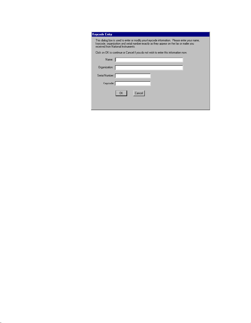
A dialog box appears, asking if you to register Lookout. If you are
ready to register Lookout, click on OK. The registration dialog box
appears.
© National Instruments Corporation 1-3 Lookout Operator’s Manual
Page 11
Chapter 1 Installing Lookout
2. Enter your name in the Name field.
3. Enter the Organization name exactly as it appears on the ke y code fax
sent in response to your registration, including punctuation marks.
This text is used in combination with the key code, and s o it m ust be
exact.
(If you have not yet recei ved your key code from National Instruments,
you can enter your regist ratio n data later. Select OK and Lookout will
inform you that you have not registered your package yet. Select OK
again until Lookout launches. )
4. Enter the Serial Number of your package. (This can be found o n your
registration form.)
5. Enter your 12 -character Keycode. The key code is not case sensitive
and you can leave the hyphens out if desired. Notice that there are no
spaces near the hyphens.
6. After completing the entries, press <Enter> or select OK.
If you enter the proper information correctly, Lookout appears on your
screen with no process running.
Lookout Operator’s Manual 1-4 www.natinst.com
Page 12
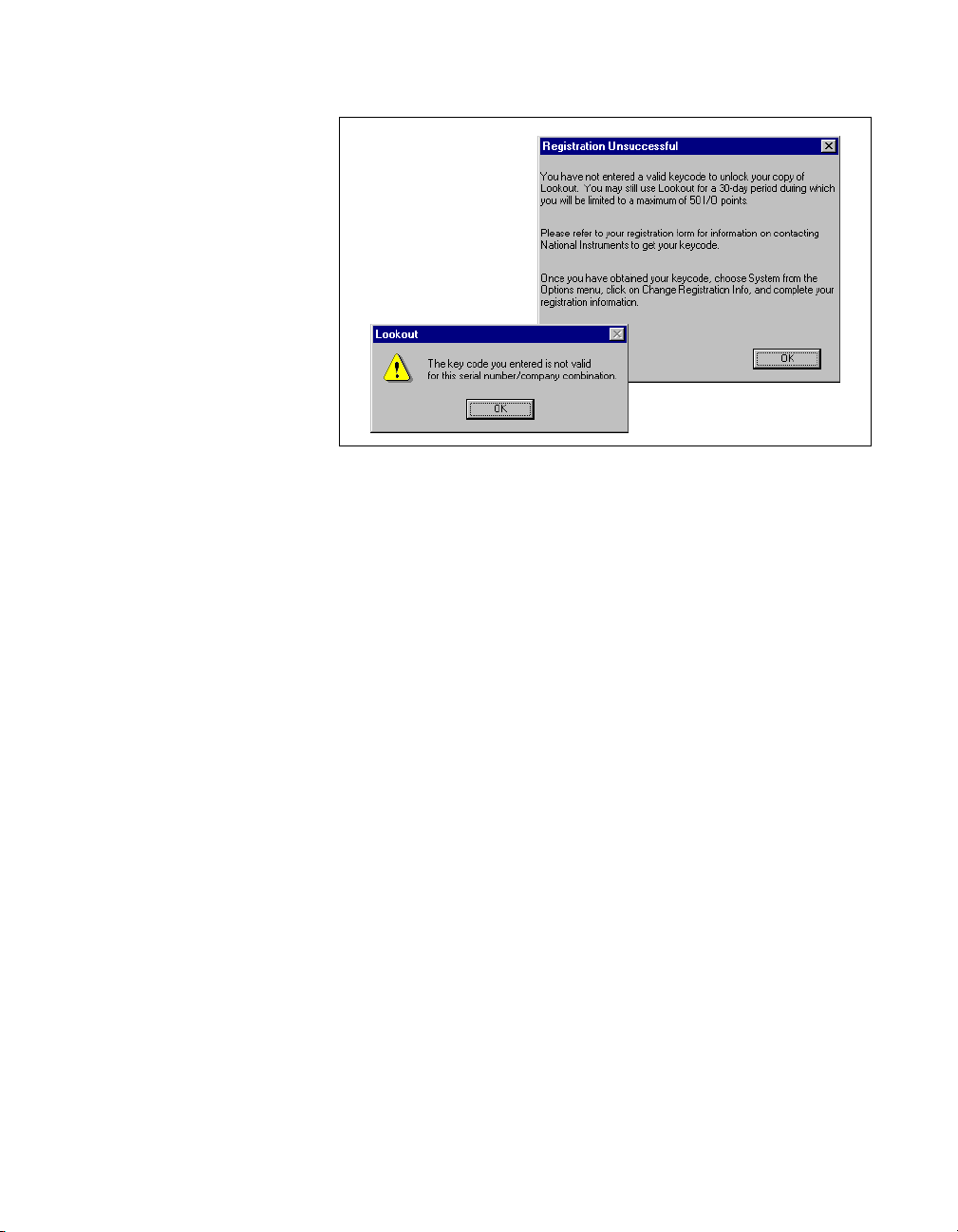
If you are certain that you typed th e information correctly and Look out
does not accept it, call the National Instruments technical support line
for help.
Changing Registration Information
If you want to change the number of Lookout I/O points you are using, or
make other changes in system capabilities, National Instruments must send
you a new Lookout keycode.
Chapter 1 Installing Lookout
T o chan ge your re gist ration inform ation, s elect Options»System»Change
Registration Info. Enter the new k eycode in the appro priate field to unlock
your additional Lookout functionality.
Adding Client Connections
You are limited in the number of client connections you are allowed to
maintain in Lookout. Just as with your I/O license, you must enter a
keycode.
Obtain your keycode by faxing your registration form to National
Instruments, or by calling.
Unlike the I/O point registration, you can add and remove client licenses
from any copy of Lookout. If you have a copy of Lookout running a server
process with two clients connected and need to increase the number of
client connections to three, you need only get a license for one more client
connection, and enter that particular ke ycode in addition to the ke ycode that
authorized your first two client connections.
© National Instruments Corporation 1-5 Lookout Operator’s Manual
Page 13
Chapter 1 Installing Lookout
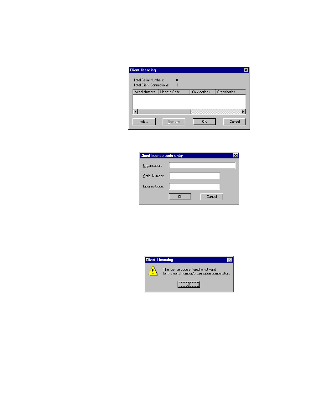
To add or change client connection in form ation in Lookout, Select
Options»System from the menu, and click on the Change Client License
button. The following dialog box appears.
Click on the Add button. The following dialog box appears.
Enter your Organization name as you reported it in your registration
request for a client keycode. Enter the Serial Number of your copy of
Lookout, and the License Code your received. Click on OK.
If your registration attempt fails, the following dialog box appears.
Check to make sure you entered your organization name, serial number,
and keycode correctly. Contact National Instruments if correcting these
entries does not fix the problem.
A newly installed version of Lookout will run with one client connection
for 30 days before reverting to demo program mode.
Lookout Operator’s Manual 1-6 www.natinst.com
Page 14
Setting System Options
The first time you open Lookou t is a good ti me to set som e of t he Looko ut
system options.
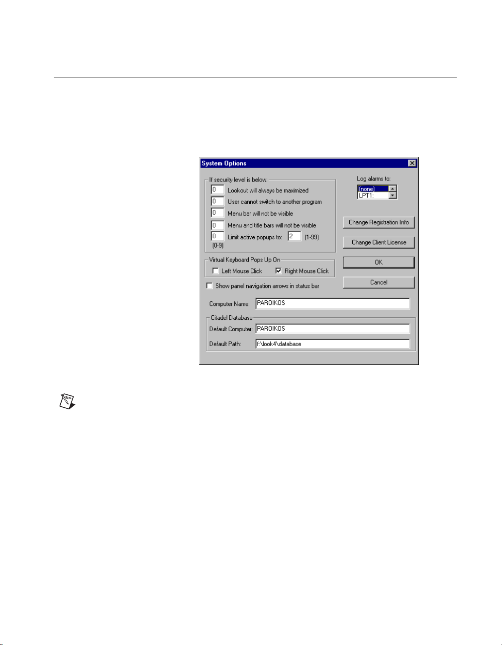
In Lookout, sele ct Options»System from the menu bar. The System
Options dialog box appears as shown in the following illustration.
Chapter 1 Installing Lookout
Figure 1-1.
Only users logged on with security levels or 9 or greater can access the System
Note
Options dialog box.
System Options Dialog Box
Computer Name Setting
The computer name field shows the network name of the computer yo u are
working on. If this field is blank, and you intend to use the networking
capability of Lookout, you need to check your network settings to make
sure your computer is properly named for network operations.
© National Instruments Corporation 1-7 Lookout Operator’s Manual
Page 15

Chapter 1 Installing Lookout
Citadel Database Settings
The Citadel Database fields set the default destination for Citadel data
logged by Lookout. All processes running under a single instance of
Lookout will use this data path to log d a ta to Citadel, unless you override
this setting when you create the process.
You set the Default path and the Default computer separately. Use the
complete path name for the Default path setting, and the fully qualified
computer name for the Default computer setting.
Virtual Keyboard Settings
Lookout features a virtual keyboard that you can access when in run mo de
by clicking on a control that accepts a text or numeric input. You can set
whether a right-click or a left-click pops up this keyboard in the Virtual
Keyboard Pops Up On field in the System Options dialog box.
Log Alarms Setting
If you have a printer directly connected to your computer, you can direct
that all alarms can be printed when they occur. Set the Log al arms to box
in the System Options dialog box to the communications port to which
your printer is connected. You can also capture a network printer port on
Windows 98/95 machines. Consult your operating system documentation
for information on this procedure.
Panel Navigation Arrows
Select the Show panel navigation arrows in status bar checkbox if you
want to use panel navigation arrows. These arrows, located in the right side
of the status bar, activate control panels in the order in which you las t
accessed them. This feature is most convenient when you have a large
number of control panels in a process and need to cycle through a subset of
them several times in a short period of time.
Security Level Settings
You may not have access to the security level settings. Consult your
Lookout system administrator for information on these settings,
if necessary.
Lookout Operator’s Manual 1-8 www.natinst.com
Page 16
Startup Process File Setting
If your computer runs Loo kout 24 hours a day, yo u may want to ensure that,
if the computer temporarily loses power, it will automatically reboot and
begin executing your processes when power returns.
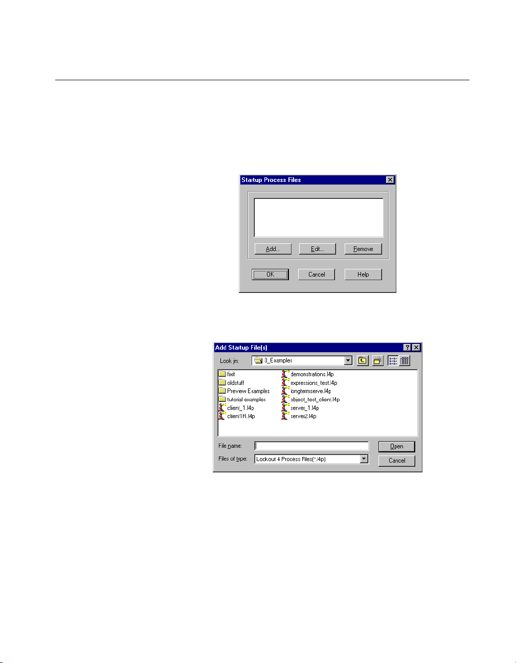
T o get startup processes, select Options »Startup, and the follo wing dialog
box appears.
To add a file to your list of startup processes, click on the Add button.
A dialog box you can use to browse for a file appears.
Chapter 1 Installing Lookout
Select the file you want to run when Lookout opens and click on Open.
You can add as many process files as you want. The files will open in the
order in which they are entered in the Startup Process Files dialog box.
To edit a path name to a file, highlight the file name and click on the Edit
button.
© National Instruments Corporation 1-9 Lookout Operator’s Manual
Page 17

Chapter 1 Installing Lookout
To make sure Lookout loads and runs when your computer boots or
reboots, consult your operating system documentation instructions on
how to set a default startup application.
Lookout Operator’s Manual 1-10 www.natinst.com
Page 18
Lookout Basics
This chapter explains how to start and get around within Lookout.
Basically , y ou use the mouse, k e yboard, touch screens, and si milar tools t o
manipulate controls on Lookout control panels. Most of what you do is as
simple as throwing a switch or adjusting a control knob.
Some operations require you to use Lookout menu items, covered in
Chapter 3, Lookout Runtime Menu Commands.
For specific information regarding the processes you are using, consult
your Lookout administrator.
Starting Lookout
Logging on to Lookout
If you are using Lookout ou tside of th e United Stat es, you may be req uired to us e a
Note
hardware key. Be sure to plug the key into the parallel port on your computer before
activating Lookout. If you do not, the program will not run.
2
Launch Lookout by selecting Start»Programs»National Instruments
Lookout»Lookout, or double-click on the Lookout icon.
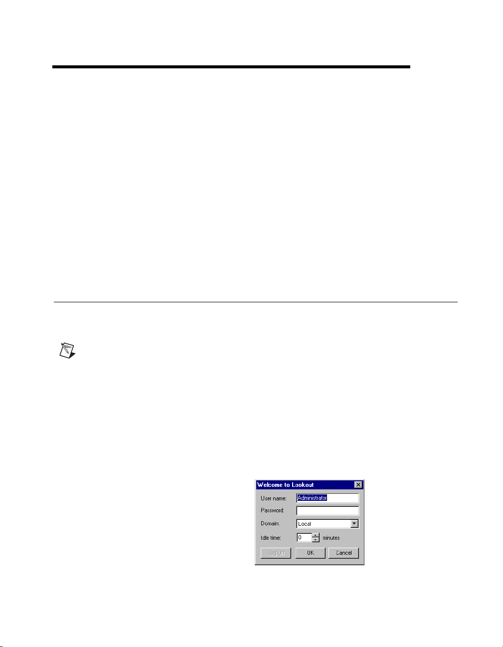
When you start or restart Lookout (after having provided regis t ration
information in y our f i rst s tartup ), yo u ar e greeted b y the lo g on dial og b ox,
as shown in the following illustration.
© National Instruments Corporation 2-1 Lookout Operator’s Manual
Page 19

Chapter 2 Lookout Basics
Your system administrator should have assigned you a user account name
and password. Enter your user name and password.
The Idle time field determines how long a period of inactivity Lookout will
wait before logging off the current user . When set to 0, Lookout leaves the
current user logged in until that user logs off, a new user logs on, or
Lookout is shut down.
The first time you start Lookout, you should see the following display if
Lookout is not running any processes. In this illustration Lookout does not
have a process file open. No monitoring or control is taking place.
If your Lookout administrator has configured Lookout to open a process
when it runs, your Looko ut screen wi ll probabl y contain your mai n contr ol
panel.
Lookout Operator’s Manual 2-2 www.natinst.com
Page 20

Chapter 2 Lookout Basics
Opening a Process File
1. If you have a Lookout process file available, select the File»Open
menu item from the Lookout menu bar.
2. In the File name data field, enter the name of a Lookout process file
(they ha ve a
and select OK.
If you select a valid process file, Lookout opens the file and immediately
begins executing the process.
When a process file opens, Lookout makes additional menu selections
available and displays control panels and the alarm window.
You can open and run as many process files at one time as you want in
Lookout, and close them individually or all together. While there is no
theoretical upper limit to how many process files you can run on one
computer, in practical terms you may begin to see degraded performance
with a very large number of processes, depending on your computer’s
hardware resources and other variables. Running multiple instances of
Lookout on one computer, or distributing Lookout processes on networked
computers can increase performance.
.l4p file extension), or choose a process file from the list
The Lookout Screen
Lookout first appears on your screen maximized, taking up the entire
screen.
Lookout has both edit and run modes. As an operator, you will be using
Lookout in Run mode only. Figure 2-1 shows a Lookout screen with
process in place in run mode.
© National Instruments Corporation 2-3 Lookout Operator’s Manual
Page 21

Chapter 2 Lookout Basics
2
1
11
3
4
5
6
78910
1 Menu Bar
2 Title Bar
3 Process Containing
Current Active Panel
4 Lookout Control Panel
5 Alarm Window
6 Active Alarms
7 Control Panel
Navigation Arrows
8 Organization
9 User Logged In
10 Time and Date
11 Minimized Control
Panel
Figure 2-1. The Lookout Screen
Title Bar
The title bar at the top of the Lookout window displays the program name
and the name of the currently active process. If a control panel is
maximized, the control panel name appears in the title b a r.
Lookout Operator’s Manual 2-4 www.natinst.com
Page 22

Menu Bar
Status Bar
Lookout Workspace
Chapter 2 Lookout Basics
The menu bar displays the currently available menu commands. Some of
these commands may or may not be available to you, depending on your
security level.
The status bar is at the bottom of the Looko ut window. When in run mode,
the status bar is gray and the time and date are d i splayed o n the lef t end o f
the bar. The account name of the curren tly log ged on o perator comes next.
The company name as entered during registration appears in the middle,
and the alarm status is on the right end of the status bar.
The Lookout workspace is the area between the menu bar and the status
bar. The workspace is the area in which you view and operate control
panels. The alarm window also appears within the workspace. You
organize and arrange control panels in this workspace area.
The visible workspace on your screen is only a window into the Lookout
virtual workspace. If control panels or their associated icons are partially
or completely outside the visible workspace, Lookout automatically
displays horizontal and vertical scroll bars along the righ t sid e and bo tto m
of the visible workspace. If scroll bars a re visible, you can scroll aroun d in
the virtual workspace to see all of your control panels.
Control Panels
Control panels provide the display area for any collection of switches,
knobs, bar graphs, digi tal displays, trend graph s, and other components t hat
you want to use to visuall y monitor and cont rol your operati ons. Panels can
be full-screen, minimized, or any size in between. You can move the panels
around the screen by grabbing the title bar of a panel with the mouse cursor
and dragging it to a new location. Control panels can also “pop up” when
an event occurs such as when a pushbutton is pressed or when an alarm is
activated.
There are three types of control panels: normal, pop-up, and pop-up with
no icon. A normal control panel can be maximized, normal size, or
minimized within the Lookout wo rkspace. A pop-up control panel in either
© National Instruments Corporation 2-5 Lookout Operator’s Manual
Page 23

Chapter 2 Lookout Basics
a pop-up state or minimized. When a pop-up control panel is displayed,
it remains on top of all other panels until you minimize it.
Control panels do not have a standard appearance. Some control panels
may only display information, while others combine control and display
information. The information displayed always represents the most current
values available to Lookout through its communications with your I/O
devices.
Control panels are wind ows in to your process you use to con trol equipment
by flipping switches, pressing buttons, and turning knobs. Individual
controls, as well as entire control panels may hav e a security le vel assigned
to them. If your security lev el is belo w that needed to operate a con trol or a
panel, you will not be able to make changes to that control or in that panel.
If you have per mission to access the object, the mouse cursor chan ges into
a hand when positioned over the object and the yo u can ad just and con trol
the object.
Control Is Accessible
Control Access Is Denied
If your security level is lower than that of the object, or if you do not have
permission to work in that process, the cursor changes into the symbol for
forbidden, and you cannot control the object.
Lookout can place copies of a control on many different contr ol panels. For
example, when you turn a knob in on e location, all copies of that k nob turn
at the same time, in each place that control is used. The same con trol object
may appear differently in each location. A potentiometer may appear as a
horizontal slide on one panel, a pair of increment/decrement buttons on
another panel, and a knob on yet another panel.
Lookout Operator’s Manual 2-6 www.natinst.com
Page 24

You can have the same sort of synchronous operation between controls in
different pro cesses running o n your computer , or between contro ls running
in processes on different computers in your network. Lookout networking
makes this possible.
Alarm Window
In Figure 2-1 the alarm window is at the bottom of the screen. You can
choose how the alarm window is displayed by selecting Alarms»Display
Options. In Figure 2-1 the alarm window is set to display at the bottom of
the workspace.
Operator Input and Navigation
There are numerous methods for you to make setpoint adjustments or
switch from one control panel to another. These include mouse, trackball,
touchscreen, and keyboard activated commands.
When the cursor moves over a controllable object, the cursor turns into a
hand, indicating you now have control of the object. Controllable objects
include such things as switches, Pots, and pushbuttons.
Chapter 2 Lookout Basics
When using a keyb oard, the arr ow keys mov e the cur sor around th e screen.
The <Tab> key jumps the cursor from one controllable object to another,
and the <Space> bar acts as the left mouse button, so you can click on a
controllable object without actually using a mouse.
You can also use keyboard function keys to control panels and other
objects, so you can switch between control panels or issue control
commands just by pressing a function key.
Your Lookout administrator can provide you with any special instructions
you need to work with a particular Lookout control panel.
Virtual Keypad
When you are in operating mode, you can click on a digital po t control and
bring up a virtual numeric keypad to enter numeric values, either with a
mouse or a touch-sensitive screen.
© National Instruments Corporation 2-7 Lookout Operator’s Manual
Page 25

Chapter 2 Lookout Basics
Virtual Keyboard
Lookout also has a virtual keyboard you can use with a touc h-sensitive
screen or a mouse.
To enable the virtual keyboard, select Options»System and then check
Left Mouse Click or Right Mouse Click in the Virtual Keyboard Pops
Up section of the dialog box.
When this feature is enabled, clicking in a data entry field or touching the
field on a touch-sensitive screen displays the virtual keyboard.
Lookout Application Files
Lookout has four unique f iles for every application: a p rocess file, a source
code file, a state file, and a security file.
Process File
Source Code File
For Lookout to run a process properly, you must have the process (
and security (
If you do not ha ve the source and state files, Lookout can recreate these f iles
from the other two.
A process file is a compiled file that contains the Lookout process you want
to run. Process files are binary files with an
name extension.
Lookout compiles a source code file to create an .l4p file. Source code
files have an
Because the binary format of Lookout process files both past and future is
subject to change for eff iciency reasons, you should always keep your
source files backed up. This is the file you will recompile to open a process
created in an older version of Lookout with any new version of Lookout
released in the future.
You can recompile Lookout source files through the Open command.
.lka) files for that process in your computer.
.l4p (Lookout Process) file
.lks (Lookout Source) file name extension.
.l4p)
.lks
Lookout Operator’s Manual 2-8 www.natinst.com
Page 26
Chapter 2 Lookout Basics
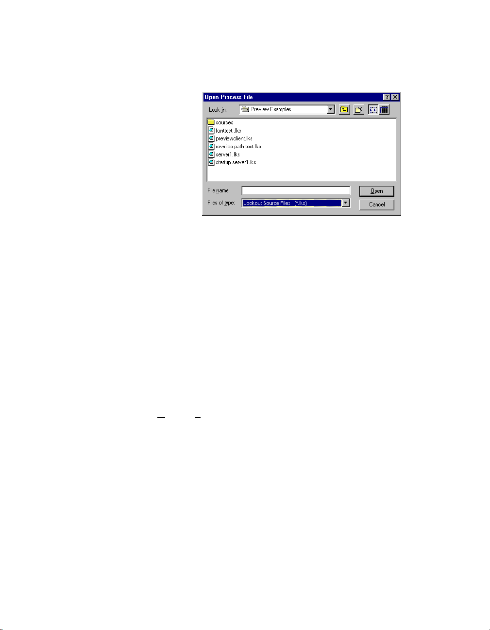
To compile a source file inside Lookout, select File»Open. The following
dialog box opens.
State File
Set the Files of type to
Lookout Source Files (*.lks) and select the
source file you want to compile.
The state file contains the actual values of object data members. These
values include setpoints and other important data held within and used by
objects. You might thin k of the state file as permanen t memory for Lookout
setpoints and real-time trends. Lookout uses the state file to store the
position of switches, potentio meters, and trend lines. When Lookout first
loads an application, it reads the appropriate state file to determine what
state the pots, switches, trend lines, and so on should be in upon startup.
The state file updates any time you save, close or exit the Lookout
application file. It can also update on a periodic basis as defined in the
System Options dialog box. You invoke this dialog box by selecting the
O
ptions»System menu command. State files have an .l4t (Lookout
State) file name extension.
© National Instruments Corporation 2-9 Lookout Operator’s Manual
Page 27

Chapter 2 Lookout Basics
Lookout Windows Services
Lookout requires three backg round services that run i n Windows outside of
the Lookout application itself to be running on your computer while it is
running: Lookout Citadel Server, Lookout Classified Ads, and Lookout
Time Synchronization. In you r Wi n dows NT t ask manag e r, these services
appear as Classifieds, TimeService, and CitadelService. Under
Windows NT, these services run automatically as NT services. If you need
to interact with these services, use the NT Services utility, found in
Start»Settings»Control Panel»Services.
In Windo ws 98/95, Look out installs a services manager during in stallation,
denoted by a small lighthouse icon at one end of your Windows task bar,
as shown in the following illustration.
When you right-click on this icon you will see the following menu.
You can start or stop any of the Lookout Windows services using this tool.
Lookout Operator’s Manual 2-10 www.natinst.com
Page 28

Lookout Runtime Menu
Commands
This chapter describes Lookout menu bar pull-down commands available
in run mode. Some menu items may be disabled, depending on your
security level.
Every menu command has a predetermined security level associated with
it. Only operators whose security levels are equal to or greater than that of
a particular command can access that menu command. Contact your
Lookout administrator to find out what security level you have.
File Commands
File»New
Security Level: 9
Shortcut Keys: <CTRL+N>
3
The F
ile»New command is the f irst step in creating a ne w pro cess file. It is
important to notice that you must use the F
command to save your work and create a new process file.
ile»Save or File»Save As
File»Open
Security Level: 8 or member of System Operator group
Shortcut Keys: <CTRL+O>
Use the F
When you select F
the current disk drive/directory and scroll through a list of process files.
Once you find the process file you want to open, click on the file name in
the file listbox or type the file name and click on the OK button, or just
double-click on the file name in the listbox.
© National Instruments Corporation 3-1 Lookout Operator’s Manual
ile»Open command to open a process file for execution.
ile»Open, a dialog box pops up that you can use to s elect
Page 29

Chapter 3 Lookout Runtime Menu Commands
If for some reason Lookout refuses to load a .l4p process file, you can
attempt to recompile by opening a Lookout
Source Files (*.lks) in the Files of Type combo box.
File»Reopen
Security Level: 8
Shortcut Keys: none
The F
ile»Reopen command reloads the currently executing process from
disk. This in turn clears all alarms from the alarm window. All trends and
setpoints, however, retain their previous values.
.lks file. Select Lookout
File»Close
Security Level: 8
Shortcut Keys: none
ile»Close command halts ex ecution of a currently loaded process file.
The F
If you are runnin g more than one pr ocess, Lookout prompts you to select
the process you want to close. Yo u can only close one process at a time with
this command.
If you made changes to your process file (such as opening the state file to
recompile) and ha v e no t saved your work, Lo oko ut f irs t pr ompts y ou t o do
so before letting you close your process.
If you made no changes, or after you have chosen to save or discard any
changes you may have made, Lookout then prompts you to make sure you
want to close the process.
The process continues to execute until you answer Yes.
Lookout Operator’s Manual 3-2 www.natinst.com
Page 30

Caution The File»Close command shuts down process execution—be sure that this is
what you want to do before selecting this command. Your Lookout application may be
controlling critical processes, and shuttin g it down could cause serious problems.
File»Close All
File»Save
Chapter 3 Lookout Runtime Menu Commands
Security Level: 8
Shortcut Keys: none
ile»Close All command halts execution of all currently loaded
The F
processes. Except that it closes all open processes, it works the same way
the F
ile»Close command does.
Security Level: 9
Shortcut Keys: none
The F
ile»Save command saves the currently executing process to disk.
Lookout replaces the old process file on disk with a new version that
reflects all changes made: new or deleted objects, different display
characteristics, new or modif ied I/O connections, setpoint adjustments, and
so on. This includes saving changes to the
files. See Chapter 2, Lookout Basics, for more information about these files.
.l4p, .lks, .l4t, and .lka
File»Save All
Security Level: 9
Shortcut Keys: none
Operates the same way the F
all open process files.
ile»Save command does, except that it saves
File»Print»Alarms and Events
Security Level: 1
Shortcut Keys: none
Use the F
select one of these commands, a dialog box appears, prompting you to
specify the time span to be printed. Use the Print Range option to specify
any arbitrary time span. See the Alarms menu items for more details on
filtering and printing alarms and events.
© National Instruments Corporation 3-3 Lookout Operator’s Manual
ile»Print commands to print alarm and event reports. When you
Page 31

Chapter 3 Lookout Runtime Menu Commands
File»Log on
Security Level: 1
Shortcut Keys: <CTRL+L>
Use the
ile»Log on
F
command to log on to Lookout as the current
operator/integrator with your predefined account name and password.
Only one person can log on at a time. You can also initiate this command
by clicking on the account box in the status bar near the bottom left corner
of the screen, where the account name appears.
Idle time
before automatically logging the current user off. Set
sets how long Lookout will run with no activity from an operator
Idle time
to 0 to stay
logged on indefinitely.
Lookout Operator’s Manual 3-4 www.natinst.com
Page 32

File»Log off
File»Exit
Chapter 3 Lookout Runtime Menu Commands
Security Level: 1
Shortcut Keys: <CTRL+L>
The F
ile»Log off command instantly logs of f the current account name and
leaves (nobody) logged onto the system. You can also initiate this command
by clicking on the account box near the bottom left corner of the screen,
where the account name appears. When the Welcome to Lookout dialog
box appears, click on the Log Off button.
Security Level: 8
Shortcut Keys: none
ile»Exit command halts the executing process and exits Lookout.
The F
After you select F
process files and asks you to verify that you want to stop the current
processes.
ile»Exit, Lookout gives you the opportunity to save the
Caution
what you want to do before selecting this command. Your Lookout application may be
controlling critical processes, and shuttin g it down could cause serious problems.
The File»Exit command shuts do wn process e x ecution—be v ery sure that this is
Edit Command
Edit»Edit Mode
Security Level: 9
Shortcut Keys: <CTRL+SPACE>
The Edit menu commands are only available when Lookout is in edit mode.
You can use edit mode to create and/or modify a process file. Only people
with a security level of 9 or membership in the Administrator group can
enter edit mode. Edit mode is not available in run-time only packages.
© National Instruments Corporation 3-5 Lookout Operator’s Manual
Page 33

Chapter 3 Lookout Runtime Menu Commands
Option Commands
Options»System
Security Level: 9
Shortcut Keys: none
The O
ptions»System command is used to configure various system-level
operating parameters. See the Setting System Options section of
Chapter 1, Inst alling Lookout, for further information on configuring
Lookout.
Options»User Manager
Security Level: 10
Shortcut Keys: none
Use the O
system user accounts. This option is only available to members of the
Administrator security group.
Lookout Operator’s Manual 3-6 www.natinst.com
ptions»User Manger command to create, revise, and delete
Page 34

Options»Serial Ports
Security Level: 9
Shortcut Keys: none
Chapter 3 Lookout Runtime Menu Commands
Use the O
ptions»Serial P orts command to conf igure your computer ser ial
port communication topology. Each serial port can have a unique setting:
Hardwired, Dial-up, or Radio (RTS/CTS). Configure your serial port
using the following instructions.
Figure 3-1.
Serial Port Settings Dialog Box
1. In the Serial port data field, select the communication port you are
defining (in this example,
COM1).
2. Define the serial port parameters for the appropriate communication
port. Refer to the remaining sections in this chapter for complete
descriptions of the parameters.
3. Click on Accept to save the parameter changes for the serial port.
4. Click on Quit to exit the dialog box.
© National Instruments Corporation 3-7 Lookout Operator’s Manual
Page 35

Chapter 3 Lookout Runtime Menu Commands
Selecting the Serial Port
The Serial port data field is a drop-down listbox. Use it to select the
communication port you are defining. While software may allow many
serial ports, most computers support only two serial ports without
additional hardware.
Setting Receive Gap
The Receive gap setting is available for all serial connection types.
This number specifies the number of empty bytes (or amount of time) a
driver receives from a controller before the driver recognizes the end of a
message frame and asks for another message. Normally, you should leave
this at the default setting of 20. However, if you are experiencing garbled
communication alarms, you might try increasing this number to allow more
time before Lookout decides it has received a complete message. For
example, with a slow baud rate of 1200, you might have to increase the
Receive gap setting to approximately 30.
Selecting the Serial Connection
Hardwired Settings
Hardwired serial connections require no hardware handshaking for line
control. Use this setting for all serial communication type s except dial-up
telephone and remote radio transceivers. You should also use this setting
when directly connecting Lookout to the Master Repeater on a radio system
or through a leased-line modem. Because a Master Repeater is a full duplex
device that does not require keying and unkeying of the frequency, it acts
much like a physically hardwired network. Other hardwired connection
types include RS-232, RS-422, RS-485, and leased telephone lines.
Radio RTS/CTS Handshaking Settings
RTS/CTS is a local hardware handshaking mechanism between the local
computer and the local commun ication device. Use the Radio (RTS/CTS)
serial connection when connecting the serial port to a device that requires
RTS/CTS hardware handshaking, such as a radio transceiver that must be
keyed up during data transmission and unkeyed during data reception.
Other half-duplex communication media such as RS-485 may require
RTS/CTS hardware handshaking. Although the RTS/CTS scheme works
identically for other RTS/CTS communication schemes, assume that you
are communicating via radio for this discussion.
Lookout Operator’s Manual 3-8 www.natinst.com
Page 36

Chapter 3 Lookout Runtime Menu Commands
When you sele ct RTS/CTS hardware handshak ing, Lookout controls the
RTS, or request-to-send pin, and monitors the CTS, or clear-to-send pin,
during data transmission (pins 4 and 5 on a 25-pin RS-232 connector).
Therefore, you must have at least the RTS pin (pin 4) wired straight
through
on your RS-232 cable. The CTS pin (pin 5) is optional.
Lookout initiates a serial transmission on an RTS/CTS port by first
asserting RTS to key the radio. Lookout then begins monitoring the state
of the CTS pin. When the radio transmitter is fully keyed and ready to
transmit, the radio asserts CTS and Lookout immediately begins data
transmission. If the radio does not assert CTS within the CTS timeout
setting (default is 100 ms), Lookout assumes the radio is ready to transmit
and transmits anyway.
The CTS timeout setting is the maximum amount of time that Lookout
waits after asserting RTS for CTS before transmitting. Most radios
typically take between 10 and 80 ms to key up. Consult your radio
specifications and DIP switch settings to determine the key-up delay on
your radio.
If your radio can assert CTS when it is ready to transmit, add about 50 ms
to the radio key-up delay specification and use this total value for the CTS
timeout. If your radio does not assert CTS, you should begin by adding
about 20 ms to your radio key-up time. Then increase this value in 10 ms
increments until the remote radio begins to correctly receive the first bytes
of the message.
Some radios may assert CTS before they are actually ready to transmit. In
this case, disconnect the CTS line (pin 5 on a 25-pin RS232 connector) an d
set the CTS timeout to a value high enough to let the radio fully key before
transmission.
After it transmits the last byte of data, Lookout continues to assert RTS,
keeping the radio keyed until the RTS delay off time period expire s. You
should set this value to the default of 0 ms, so that Lookout unkeys the radio
as soon as possible to prepare to receive the response.
When unkeyed, most radi os generate an audible squelch tail that the remo te
device might decode as unexpected garbage bytes. Some remote devices
reject the entire message instead of just decoding the valid data and
ignoring the extra garbage bytes. In this case, keep the radio keyed for
several milliseconds using the RTS delay off setting. This time period
delays the squelch tail long enough for the remote device to recognize the
last data frame as valid before receiving garbage bytes caused by the
squelch tail.
© National Instruments Corporation 3-9 Lookout Operator’s Manual
Page 37

Chapter 3 Lookout Runtime Menu Commands
If you set the RTS delay off setting too high, the remote device begins
transmitting its response before the local radio is u nkeyed, causing a
communication alarm in Lookout.
Dial-Up Modem Settings
Use the Dial-up serial connection when you use a modem in conjunction
with a switched telephone line (not leased line). You can customize the
dial-up settings for your particular modem and phone line.
The default Dialing pr e fix settings are based on the Hayes Corporation
AT command set, which is an industry standard for data modems. The
following table explains the Lookout default settings. For additional
commands, refer to your modem operation manual.
Prefix Description
AT Attention code that must precede all commands
D Dial phone number with these modifiers: P for pulse;
Table 3-1.
T for tone
Dialing Prefix Default Settings
E Local echo mode: E for no echo
M Speaker on or off: M for speaker always off
V Verbal or numeric result codes: V for numeric result codes
X Result code and dialing opti ons : X4 waits for dial tone
before dialing, and recognizes busy signal
When you use an external dial-up modem with Lookout, the DTR line in
your cable between the modem and the computer must be wired straight
through. This line is pin 20 on a 25-pin RS-232 connector and pin 4 on a
9-pin connector. Lookout uses the DTR line to command the modem to
disconnect (hang up) and return to the command mode.
Some factory modems are not conf igured to respo nd to the DTR line. After
Lookout first successfully dials out to a remote modem and finishes the
polling cycle, it drops the DTR line, but the modem remains connected. If
the modem does not respond after several seconds of Lookout attempting
to raise and drop the DTR line, Lookout generates an alarm stating that the
modem is not responding. If you receive this alarm message, your modem
is not configured to monitor the DTR line.
Lookout Operator’s Manual 3-10 www.natinst.com
Page 38

Chapter 3 Lookout Runtime Menu Commands
The Hayes Corporation standard command for configuring the modem to
hang up and enter command mode upon loss of DTR is
&D2. You can use
a terminal program to make this setting permanent on most mod ems by
entering the modem command
in nonvolatile modem memory. Or you can just add
prefix. The default Dialing prefix is
to
AT&D2X4MVEDT.
AT&D2&W to store the setting permanently
&D2 into the Dialing
ATX4MVEDT , so you might change it
Retries specifies the number of times Lookout dials the specified phone
number and attempts to connect to the modem at the other end of the line.
If Lookout fails to connect after the specified Retries, it generates an alarm
and moves on to the next phone number in the polling queue (if a queue
has formed).
Wait for connection specifies the length of time Lookout waits to receive
a connect signal back from the modem it is calling. The time period begins
when Lookout first sends the local modem the dialing prefix command. The
time should be long enough for the local modem to receiv e a dial tone, dial
the phone number, allow the remote modem to pick up the line, and send
back a connect message. If the specified time is too short, your system
could be operating correctly but never make a connection.
Pause between calls is the length of time Lookout waits after hanging
up before it sends the local modem the next dialing prefix signal. If the
specified time is too brief, your system may not hang up the existing call
but instead attempt to call the next number.
Note Your specific modems, radios, and local phone lines may operate faster or slower
than the default settings. You may need to use a trial-and-error approach to find the best
settings for your system.
Options»Import APT Database
The Options»Import APT Database command only appears if a Tiway
object exists in the currently executing process file. Choose this command
to import an APT tag file and create new database members for the selected
Tiway object.
Options»Modbus
When you create a Modbus object, Lookout adds the Options»Modbus
item. Selecting this item displays Modbus statistics.
© National Instruments Corporation 3-11 Lookout Operator’s Manual
Page 39

Chapter 3 Lookout Runtime Menu Commands
Alarm Commands
Alarms»Show
Security Level: 1
Shortcut Keys: <CTRL+A>
The A
larms»Show command instantly displays the alarm window as a
floating style window if it is not already being displayed. Y ou can select this
command when you want to quickly and easily locate the alarm window
from any location on any control panel. Notice the shortcut keystroke,
<CTRL+A>. You can also call the alarm window by clicking on the alarm
box in the far right end of the status bar at the bottom of the screen.
Alarms»Display Options
Security Level: 1
Shortcut Keys: none
larms»Display Options command changes the display style of the
The A
alarm window (top, bottom, floating). You can also use this command to
modify internal alarm display formats such as font, header, and various
alarm information.
The Window style determines the position of the alarms w ind ow in the
Lookout workspace. If you select Floating, the alarms window appears as
a pop-up style control panel that you can resize and move on the screen.
You can minimize a floating alarms window at any time.
If you use either the Top or Bottom window type, the Window height
specifies the number of alarms Lookout can display in the alarms window.
The actual height of the alarms window adjusts aut omatically depending on
the selected font and Window height setting. You can resize a floating
alarms window at any time with the sizing border. If more alarms occur
Lookout Operator’s Manual 3-12 www.natinst.com
Page 40

than can be displayed in the alarms window at once, a scroll bar appears
along the right side of the window.
The following illustration shows an alarms window with Window style set
to Bottom, and Window height set to 4.
Alarms»Filter Options
Security Level: 2
Shortcut Keys: none
Chapter 3 Lookout Runtime Menu Commands
Use the A
larms»Filter Options command to filter the alarms displayed in
the alarm window by group, priority, and occurrence.
The following dialog box appears.
To monitor alarms with specific priorities, set the Min and Max values of
the Priority criterion.
Setting User Name restricts your alarm monitoring to alarms generated
while that particular user is logged on. You can only select one user name
at a time, but you can use wild card characters to widen the scope of the
alarms reported.
© National Instruments Corporation 3-13 Lookout Operator’s Manual
Page 41

Chapter 3 Lookout Runtime Menu Commands
Setting Ack User Name restricts your alarm monitoring to alarms
acknowledged by that particular user. You can only enter one user name at
a time, but you can use wild card characters to widen the scope of the
alarms reported.
The Ack Comment filter restricts your alarms displayed to those with the
specified acknowledgem ent comment.
Setting Object Name restricts your alarm monitoring to alarms involving
the name you enter . You can only enter one name at a time, but you can use
wild card characters to widen the scope of those objects reported.
Setting Description restricts your monitoring alarms that meet your
criteria. Y ou can only choose one description categor y at a time, but you can
use wild card characters to widen the scope of the alarms reported. The
Lookout categories HiHi, Hi, Lo, or LoLo are added as a prefix to any
descriptions, and are transparent to description filtering.
Setting Area Name restricts your monitoring to the alarm area you choose.
You can only enter one alar m area at a time. (Lo okout 4 alarm areas are the
same thing as Lookout 3.xx alarm groups.)
Use the Browse Areas button to locate and select the alarm area you want
to use as a filter.
You can choose to have the Lookout alarm window show alarms only,
events only, or both alarms and events by checking the appropriate box in
the Show section of this dialog box.
Use the parameters in the Old Alarms section to display alarms after they
have been acknowledged.
Selecting Audible Alarms enables a sound alert when an alarm takes
place. The sound depends on your Windows system setting for error
sounds.
Alarms»Print
Security Level: 1
Shortcut Keys: none
larms»Print command invokes a dialog box you can use to specify
The A
the time period of the alarms you want to print.
Lookout Operator’s Manual 3-14 www.natinst.com
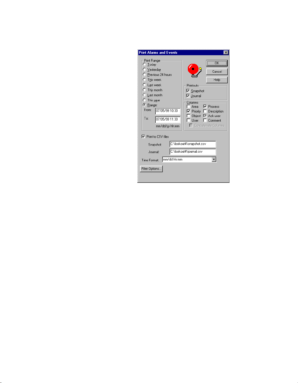
Page 42
The following dialog box appears.
Chapter 3 Lookout Runtime Menu Commands
Select the time range you want to print alarms and events from with the
items in the Print Range section of the dialog box. Notice that when
defining your own range you use month and day followed by hour and
minute.
The Printouts selections determine the exact alarm information included
in your printout. Snapshot only prints the status of alarms at the be ginning
of the specified Range b ut does not indicate what happened d uring the time
span. Journal creates a printout of everything that happened during the
time span from the beginning of the Range.
Specific information about each alarm is presented in columnar format.
Lookout prints only the information you designate. Select which columns
you want printed in the Columns section of the dialog box.
To print to a comma-separated file (
.csv), select the Print to CSV file
option. Enter the filenames for Snapshot and Journal files, including the
path to where you want the files written. A relative path will be relative to
the Lookout directory. If you enter the filename only, Lookout saves this
file to your Lookout directory.
© National Instruments Corporation 3-15 Lookout Operator’s Manual
Page 43

Chapter 3 Lookout Runtime Menu Commands
Set the format for printing times in the Time Fo rmat list.
You can adjust your alarm filters for printing by clicking on the Filter
Options button to access the alarm filter options
Note You can print alarms as they happen by specifying a printer port in the Log alarms
to field of the System Options dialog box, accessed by selecting Options»System from
the menu bar. This works well for a printer directly connected to yo ur computer. To print
alarms directly to a networ k computer , you must capture a port in the netw ork printer dri ver
and link it to your networked printer. Consult your operating system documentation for
detailed instructions on how to capture a port for a printer driver.
Alarms»Select All
Security Level: 2
Shortcut Keys: none
The A
larms»Select All command is a shortcut method for sel ecting all
visible or non-filtered alarms for acknowledgment. Alarms that are not
visible because of filtering or because the alarm window is minimized will
not be selected. This is especially useful if your process is experiencing
high numbers of alarms. Selecting each alarm individually can be very
time consuming.
Alarms»Deselect All
Security Level: 2
Shortcut Keys: none
This command is a shortcut method for deselecting all alarms that are
currently selected for acknowledgment. If you want to deselect only
specific alarms, click on the individual alarm line.
Alarms»Acknowledge
Security Level: 2
Shortcut Keys: none
Operators select the A
alarms that are currently selected for acknowledgment.
If you select one or more alarms for acknowledgment, a dialog box appears
for you an operator to enter a comment concerning the alarm. Comments
are optional, and you can click on OK to finish acknowledging alarms
without entering a comment. You can search the database for alarms or
Lookout Operator’s Manual 3-16 www.natinst.com
larms»Acknowledge command to acknowledge
Page 44

print out the day’s alarms based on comments, so using certain standard
comments (in addition to circumstantial comments) can make the filtering
process easier.
Alarms»Acknowledge All
Security Level: 2
Shortcut Keys: none
Chapter 3 Lookout Runtime Menu Commands
Alarms»Properties
Select the A
currently active alarms.
Security Level: 2
Shortcut Keys: none
Select the A
alarm. This option is also available when you right-click on an alarm in the
alarm window.
larms»Acknowledge All command to acknowledge all
larms»Properties to see detailed information about a selected
© National Instruments Corporation 3-17 Lookout Operator’s Manual
Page 45

Chapter 3 Lookout Runtime Menu Commands
Right-click on an alarm and select Properties. The following dialog box
listing specific information about the alarm or event appears.
You can scroll through alarms and events using the Previous and Next
buttons of this dialog.
Window Commands
Window»Arrange Icons
Window»Arrange Icons arranges the control panel icons across the
bottom of the Lookout workspace in neat columns and rows. Lookout
spaces them according to the setting for icon spacing in the Microsoft
Windows Control Panel.
Window»Minimize All
Window»Minimize All minimizes all control panels and displays their
icons across the bottom of the Lookout workspace.
Title
Window»
Lookout Operator’s Manual 3-18 www.natinst.com
n
The titles of all control panels appear at the bottom of the Window menu,
each with a number you can use when selecting panels with the keyboard
instead of the mouse. You can locate a particular panel by finding its title in
this list and selecting it. Lookout then displays the panel in the workspace.
Of course, if the panel is outside of the visible workspace, you may have to
scroll around in the workspace to make the panel visible.
Page 46

Window»More Windows
If you have too many control panels to fit in the Window menu, the More
Windows command appears at the bottom of the Window menu. The
indow»More Windows command pops up a dialog box you can use to
W
scroll through the control panel titles and select the window to display by
double-clicking on the panel title.
Run Commands
Run»Add
Security Level: 9
Shortcut Keys: none
The R
submenu list. Operators subsequently in v oke these commands with a click
of the mouse—without leaving Lookout. For instance, you might want to
print a custom report on demand. The following example loads Excel and
runs the macro
places it into a preconfigured report template, and sends it to the printer.
Consult your Excel documentation for more information on writin g your
macros.
Chapter 3 Lookout Runtime Menu Commands
un»Add command adds up to ten DOS-style commands to the run
daily.xlm, which pulls historical data off the hard drive,
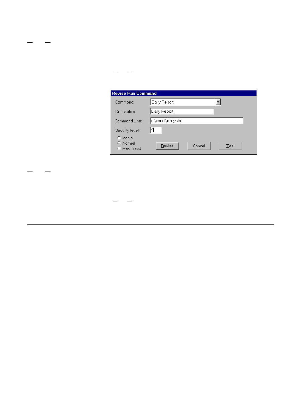
The Security level setting applies to any command you add or re vise . This
means you can configure mu ltiple comman ds, some of which may o nly be
invoked b y high level operators. The following illustration shows the Run
menu with the Daily Report item added.
© National Instruments Corporation 3-19 Lookout Operator’s Manual
Page 47
Chapter 3 Lookout Runtime Menu Commands
Run»Revise
Security Level: 9
Shortcut Keys: none
Use the R
commands.
Run»Delete
Security Level: 9
Shortcut Keys: none
Use the R
Help Commands
Help»Contents
Select Help»Contents to access the Lookout help system. Many of the
topics in the help system apply to development of Lookout processes, but
you can also find informat ion that may be helpful for oper ational problems .
un»Revise command to modify previously configured run
un»Delete to remove previously configured run commands.
Help»About Lookout
Select Help»About Lookout to access information on the copy of Lookout
you are running, the version of Windows you are running in, and the
processes currently running on your version of Lookout.
Lookout Operator’s Manual 3-20 www.natinst.com
Page 48

Technical Support Resources
This appendix describes the comprehensive resources available to you in
the Technical Support section of the National Instruments Web site and
provides technical support telephone numbers for you to use if you have
trouble connecting to our Web site or if you do not have internet access.
NI Web Support
To provide you with immediate answers and solutions 24 hours a day,
365 days a year, National Instruments maintains ex tensive on line technical
support resources. They are available to you at no cost, are updated daily,
and can be found in the Technical Support section of our Web site at
www.natinst.com/support.
Online Problem-Solving and Diagnostic Resources
• KnowledgeBase—A searchable database containing thousands of
frequently asked questions (FA Qs ) and their co rresponding ans wers or
solutions, including special sections devoted to our newest products.
The database is u pdated daily in response to new customer e xperiences
and feedback.
• Troubleshooting Wizards—Step-by-step guides lead you through
common problems and an swer question s about our entire product line.
Wizards include screen shots that illustrate the steps being described
and provide detailed information ranging from simple getting started
instructions to advanced topics.
• Product Manuals—A comprehensive, searchable library of the latest
editions of National Instruments hardware and software product
manuals.
• Hardware Reference Database—A searchable database containing
brief hardware descriptions , mechanical drawin gs, and helpful images
of jumper settings and connector pinouts.
• Application Notes—A library with more than 100 short papers
addressing specific topics such as creating and calling DLLs,
developing your own instrument driver software, and porting
applications between platforms and operating systems.
A
© National Instruments Corporation A-1 Lookout Operator’s Manual
Page 49

Appendix A Technical Support Resources
Software-Related Resources
• Instrument Driver Network—A library with hundreds of instrument
drivers for cont r ol of s t and alone i n st ru ments vi a GPIB, VXI, or serial
interfaces. You also can submit a request for a particular instrument
driver if it does not already appear in the library.
• Example Programs Database—A database with numerous,
non-shipping example programs for National Instruments
programming environments. You can use them to complement the
example programs that are already included with National I nstruments
products.
• Software Library—A library with updates and patches to application
software, links to the latest versions of driver software for National
Instruments hardware products, and utili ty routines.
Worldwide Support
National Instruments has offices located around the globe. Many branch
offices maintain a Web site to provide information on local services. You
can access these Web sites from
www.natinst.com/worldwide.
If you have trouble connecting to our Web site, please contact your local
National Instruments office or the source from which you purchased your
National Instruments product( s) to obtain su pport.
For telephone support in the United States, dial 512 795 8248. For
telephone support outside the United States, contact your local branch
office:
Australia 03 9879 5166, Austria 0662 45 79 90 0, Belgium 02 757 00 20,
Brazil 011 284 5011, Canada (Calgary) 403 274 9391,
Canada (Ontario) 905 785 0085, Canada (Québec) 514 6 94 8521,
China 0755 3904939, Denmark 4 5 76 26 00, Finland 09 725 725 11,
France 01 48 14 24 24, Germany 089 741 31 30, Greece 30 1 42 9 6 427
Hong Kong 2645 3186, India 91805275406, Israel 03 6120092,
Italy 02 413091, Japan 03 5472 2970, Korea 02 596 7456,
Mexico (D.F.) 5 280 7625, Mexico (Monterrey) 8 357 7695,
Netherlands 0348 433466, Norway 32 27 73 00, Singapore 2265886,
Spain (Barcelona) 93 582 0251, Spain (Madrid) 91 640 0085,
Sweden 08 587 895 00, Switzerland 056 200 51 51,
Taiwan 02 2377 1200, United Kingdom 01635 523545
Lookout Operator’s Manual A-2 www.natinst.com
Page 50

Glossary
Prefix Meaning Value
m- milli- 10
k- kilo- 10
M- mega- 10
A
alarm Software notification of a condition in a process. This alarm may call
attention of a value that has exceeded or fallen below certain levels, set in
the object database or in an Alarm object.
C
Citadel The Lookout historical database that stores your data for access later.
client A Lookout process t hat monitors a Look out server process. Lookout cli ents
should be computer independ ent so that the y can be run from any comp uter
on your network. Lookout server processes run on computers actually
connected to your control hardware.
–3
3
6
comm port Term sometimes used for a serial port.
connection Input to a Look out object’s w ritable data memb er s.
control objects Lookout objects you use to control a process, change a data v alue, adjust a
register, and so on.
controllable objects Lookout objects you can control with a Lookout control object.
CTS Clear to Send. Part of a handshaking protocol for certain devices that
connect the serial port of a computer.
© National Instruments Corporation G-1 Lookout Operator’s Manual
Page 51

Glossary
D
data member Data source or sink associated with a Lookout object. A readable data
member, or source, may be used in expr essions or as inpu ts to other
objects. A writable d ata m embe r, o r s ink, may ha ve a t m ost o ne
connection into it, created using the Object»Edit Connections dialog
box. A data member may be both reada ble and writable .
database Collection of data stored for later retrieval, display, or analysis.
dialing prefix Part of the Hayes AT command set for use with modems.
displayable objects A Lookout object class that has a displayable component, such as a Pot,
a Switch, or a Pushbutton.
E
edit mode Lookout mode in which you can alter and create objects within a process.
Switch in and out of edit mode by pressing <Ctrl-space> or by selecting
Edit»Edit Mode.
Ethernet A widely used, standardized local area networking technology, specified in
the IEEE 802.3 standard.
event Anything that happens can be an event. In Lookout, events include such
things as adjusting a control value, entering or exiting edit mode, opening
or closing a control panel, and logging in or logging out of the system.
expressions Lookout expressions are often paths to a data member. They can also
function like variables tha t, using a spread sheet cell typ e fo rmula, beco me
capable of performing flexible, real-time math operations, condition
testing, and other complex operations functions.
Lookout Operator’s Manual G-2 www.natinst.com
Page 52

Glossary
F
frame Sequence of by tes sen t fr om a com pute r to a d ev ice o r vi ce v er sa. T he
syntax of the frame d ep ends o n th e pro toc ol being use d. A re ad fra me
contains enough information to specify a set of variables whose values
the device should return. A write frame specifies a variable in the device
and a new value to write into that variable. Some protocols support the
writing of multiple variables in a single frame. A response frame is
returned from the device to the computer, indica ting whether the f rame
just sent to it was received successfully. If the frame just received was
a read frame, the response frame contains a set of requested values.
H
hi and hihi Alarm settings. Both warn that a value has gone above some setpoint.
Generally a Hi alarm is used to alert an op erator of a need for interv ention.
A hihi alarm is usually used to alert an operator that the value has been
exceeded by an e ven greater m argin than a hi alarm indicates, and is usually
used to indicate an urgent need for action.
historical logging The process of storing data in a database for use at another time, or from
another location.
HOA Hand-Off-Auto control, used to set whether a value must be changed
manually, is completely turned off, or functions automatically . You can use
a Pot object and a complex expression to create this sort of control in
Lookout, or you can use a Radi oButton obj ect, depen ding on th e particu lar
requirements of the task you need to accomplish.
I
I/O point Every read-only, write-only, or read-write connection Lookout makes to
external hardware is counted as an I/O point. Lookout is licensed for use
with a set number of I/O points. If you exceed the number yo u are licensed
to use with your copy of Lookout, a warning message appears on your
computer screen warning you to shut down one of your processes within a
specified time before Lookout cuts back on I/O usage.
© National Instruments Corporation G-3 Lookout Operator’s Manual
Page 53

Glossary
L
.l4p files File extension for Lookout process files. These are the compiled files
Lookout runs when it runs a process.
.l4t files File extension for a Lookout state file, which stores the values for Lookout
controls and other objects with state information.
.lka files File extension for Lookout security files.
.lkp files File extension for Lookout process files in versions of Lookout earlier than
Lookout 4.
.lks files File extension for a Lookout source file, which Lookout compiles to make
a Lookout process file that Lookout can run. This is the file you should
make sure you keep backed up in case you need to recreate a corrupted
process file, or in case some future version of Lookou t cannot run a process
file compiled in an earlier version of Lookout.
O
ODBC Open DataBase Connectivity, a standard application programming
interface (API) for accessing a database. You can use ODBC statements to
access files in a number of different databases, including Access, dBase,
DB2, and Excel.
ODBC is compatible with the Structured Query Language (SQL)
Call-Level Interfa ce. ODBC handles SQL requests by conv erting them into
requests an ODBC database can use.
P
process In Lookout, process refers to a Lookout “program”, used for industrial
automation, control, monitoring, or reporting.
process file The Lookout binary f ile Look out ex ecutes when runn ing a process. Car ries
the
.l4p extension.
Lookout Operator’s Manual G-4 www.natinst.com
Page 54

Glossary
R
receive gap A serial communications setting that determines the number of empty bytes
(or amount of time) a driver receives before recognizing the end of a
message frame and requesting another message.
RTS Request to Send, part of a handshaking protocol for certain devices that
connect the serial port of a computer.
S
security accounts Also called user and group accounts, Lookout uses security accounts to
define what users or group of users have different operation privileges in
Lookout.
server A process that provides data (services) to client processes. In Lookout,
server processes are intended to be run on one computer only, with direct
connections to field hardware. Client processes interact with field hardware
through server processes.
source file Lookout file that can be compiled to produce a binary Loo kout process f ile
that runs a process. Uses a
.lks file extension.
state file The Lookout file that stores the value of all Lookout control parameters and
object data members in use in a process. Uses the file extension
system objects Lookout objects used to control other objects or process and analyze data.
.l4t.
T
TCP Transmission Control Protocol, a method (protocol) for sending data
between computers. Used with IP, the Internet Protocol.
TCP/IP TCP/IP sends data as packets, with IP handling the delivery of data and
TCP keeping track of the individual packets.
© National Instruments Corporation G-5 Lookout Operator’s Manual
Page 55

Index
A
About Lookout command, 3-20
Acknowledge command, Alarm
menu, 3-16 to 3-17
Acknowledge All command, Alarm menu, 3-17
Add command, Run menu, 3-19
adding client connections, 1-5 to 1-6
Alarm commands, 3-12 to 3-18
Acknowledge, 3-16 to 3-17
Acknowledge All, 3-17
Deselect All, 3-16
Display Options, 3-12 to 3-13
Filter Options, 3-13 to 3-14
Print, 3-14 to 3-16
Properties, 3-17 to 3-18
Select All, 3-16
Show, 3-12
alarm window, 2-7
application files, 2-8 to 2-9
process file, 2-8
source code file, 2-8 to 2-9
state file, 2-9
Arrange Icons command, 3-18
C
Citadel Database settings, 1-8
client connections, adding, 1-5 to 1-6
Close command, 3-2 to 3-3
Close All command, 3-3
computer name setting, 1-7
Contents command, Help menu, 3-20
control panels
copies of controls, 2-6
purpose and use, 2-5 to 2-7
types of control panels, 2-5 to 2 -6
conventions used in manual, iv
D
Delete command, Run menu, 3-20
Deselect All command, Alarm menu, 3-16
diagnostic resources, online, A-1
dial-up modem settings, 3-10 to 3-11
Display Options command, Alarm
menu, 3 -12 to 3-13
E
Edit Mode command, 3-5
Exit command, 3-5
F
File commands, 3-1 to 3-5
Close, 3-2 to 3-3
Close All, 3-3
Exit, 3-5
Log off, 3-5
Log on, 3-4
New, 3-1
Open, 3-1 to 3-2
Print, 3-3 to 3-4
Reopen, 3-2
Save, 3-3
Save All, 3-3
Filter Options command, Alarm
menu, 3 -13 to 3-14
H
handshaking settings, radio RTS/CTS,
3-8 to 3-10
hardware key for Lookout (note), 1-3
hardware requirements, 1-1
hardwired serial connections, 3-8
© National Instruments Corporation I-1 Lookout Operator’s Manual
Page 56

Index
Help commands
About Lookout, 3-20
Contents, 3-20
I
Import APT Database command, 3- 11
installing Lookout, 1-2
I/O points
changing number of, 1-5
for unregistered Lookout package, 1-3
K
keycode
adding client connections, 1-5
registering Looking, 1-4
L
log alarms settings, 1-8
Log off command, 3-5
Log on command, 3-4
logging on to Lookout, 2-1 to 2-2
Lookout. See also Runtime menu commands.
application files, 2-8 to 2-9
process file, 2-8
source code file, 2-8 to 2-9
state file, 2-9
hardware and software requirements, 1-1
installing, 1-2
operator inp ut and navigation, 2-7 to 2-8
virtual keyboard, 2-8
virtual keypad, 2-7
registering, 1-3 to 1-6
adding client connections, 1-5 to 1-6
changing registration
information, 1-5
limitations of unregistered
package, 1-3
starting Lookout for first time,
1-3 to 1-5
setting system options, 1-7 to 1-8
starting, 2-1 to 2-3
startup process file setting, 1-9 to 1-10
TCP/IP networking, 1-2
Windows services, 2-10
Lookout Citadel Server, 2-10
Lookout Classified Ads, 2-10
Lookout screen, 2-3 to 2-7
alarm window, 2-7
control panels, 2-5 to 2-7
menu bar, 2-5
process in place in run mode (figure), 2-4
status bar, 2-5
title bar, 2-4
workspace, 2-5
Lookout Time Synchronization, 2-10
M
menu bar, 2-5
Minimize All command, Window menu, 3-18
Modbus command, 3-11
More Windows command, 3-19
N
National Instruments Web support, A-1 to A-2
New command, 3-1
O
online problem-solving and diagnostic
resources, A-1
Open command, 3-1 to 3-2
operator input and navigation, 2-7 to 2-8
virtual keyboard, 2-8
virtual keypad, 2-7
Lookout Operator’s Manual I-2 www.natinst.com
Page 57

Index
Option commands, 3-6 to 3-11 . See also
system options, setting.
Import APT Database, 3-11
Modbus, 3-11
Serial Ports, 3-7 to 3-11
System, 3-6
User Manager, 3-6
P
panel navigation arrows, 1-8
Print command
Alarm menu, 3-14 to 3-16
File menu, 3-3 to 3-4
problem-solving and diagnostic resources,
online, A-1
process file
definition, 2-8
opening, 2-3
Properties command, Alarm
menu, 3-17 to 3-18
R
radio RTS/CTS handshaking
settings, 3-8 to 3-10
receive gap, setting, 3-8
registering Lookout, 1-3 to 1-6
adding client connections, 1-5 to 1-6
changing registration information, 1-5
limitations of unregistered package, 1-3
starting Lookout for first time, 1-3 to 1-5
Reopen command, 3-2
Revise com mand, Run menu, 3-20
Run commands, 3-19to 3-20
Add, 3-19
Delete, 3-20
Revise, 3-20
Runtime menu commands, 3-1 to 3-20
Alarm commands, 3-12 to 3-18
Edit command, 3-5
File commands, 3-1 to 3-5
Help commands, 3-20
Option commands, 3-6 to 3-11
Run commands, 3-19 to 3-20
Window commands, 3-18 to 3-19
S
Save command, 3-3
Save All co mmand, 3-3
security level settings, 1-8
Select All command, Alarm menu, 3-16
serial number for Lookout, 1-4
Serial Ports command, 3-7 to 3-11
receive gap setting, 3-8
serial connection selection, 3-8 to 3-11
dial-up modem settings, 3-10 to 3-11
hardwired settings, 3-8
radio RTS/CTS handshaking
settings, 3-8 to 3-10
serial port selection, 3-8
Serial Port Settings dial og box
(figure), 3-7
Show command, Alarm menu, 3-12
software requirements, 1-1
software-related resources, A-2
source code file, 2-8 to 2-9
starting Lookout
for first time, 1-3 to 1-5
logging on, 2-1 to 2-2
opening process file, 2-3
startup process file setting, 1-9 to 1-10
state file, 2-9
status bar, 2-5
System command, 3-6
system options, setting, 1-7 to 1-8
System Options Dialog Box (figure), 1-7
© National Instruments Corporation I-3 Lookout Operator’s Manual
Page 58

Index
T
TCP/IP networking, 1-2
technical support resources, A-1 to A-2
title bar, 2-4
nTitle command, Window menu, 3-18
U
User Manager command, 3-6
V
virtual keyboard
operating, 2-8
settings, 1-8
virtual keypad, 2-7
W
Web support from National Instruments,
A-1 to A-2
online problem-solving and diagnostic
resources, A-1
software-related resources, A-2
Window commands, 3-18 to 3-19
Arrange Icons, 3-18
Minimize All, 3-18
More Windows, 3-19
nTitle, 3-18
Windows services, 2-10
workspace for Lookout, 2-5
Worldwide technical support, A-2
Lookout Operator’s Manual I-4 www.natinst.com
 Loading...