

Page 1

™
NI-DSP
Software Reference Manual
for LabVIEW
Digital Signal Processing Software for the PC
December 1993 Edition
Part Number 320571-01
®
for Windows
© Copyright 1993 National Instruments Corporation.
All Rights Reserved.
Page 2

National Instruments Corporate Headquarters
6504 Bridge Point Parkway
Austin, TX 78730-5039
(512) 794-0100
Technical support fax: (800) 328-2203
(512) 794-5678
Branch Offices:
Australia (03) 879 9422, Austria (0662) 435986, Belgium 02/757.00.20, Canada (Ontario) (519) 622-9310,
Canada (Québec) (514) 694-8521, Denmark 45 76 26 00, Finland (90) 527 2321, France (1) 48 14 24 24,
Germany 089/741 31 30, Italy 02/48301892, Japan (03) 3788-1921, Netherlands 03480-33466, Norway 32-848400,
Spain (91) 640 0085, Sweden 08-730 49 70, Switzerland 056/20 51 51, U.K. 0635 523545
Page 3

Limited Warranty
The media on which you receive National Instruments software are warranted not to fail to execute programming
instructions, due to defects in materials and workmanship, for a period of 90 days from date of shipment, as
evidenced by receipts or other documentation. National Instruments will, at its option, repair or replace software
media that do not execute programming instructions if National Instruments receives notice of such defects during
the warranty period. National Instruments does not warrant that the operation of the software shall be uninterrupted
or error free.
A Return Material Authorization (RMA) number must be obtained from the factory and clearly marked on the
outside of the package before any equipment will be accepted for warranty work. National Instruments will pay the
shipping costs of returning to the owner parts which are covered by warranty.
National Instruments believes that the information in this manual is accurate. The document has been carefully
reviewed for technical accuracy. In the event that technical or typographical errors exist, National Instruments
reserves the right to make changes to subsequent editions of this document without prior notice to holders of this
edition. The reader should consult National Instruments if errors are suspected. In no event shall National
Instruments be liable for any damages arising out of or related to this document or the information contained in it.
EXCEPT AS SPECIFIED HEREIN, NATIONAL INSTRUMENTS MAKES NO WARRANTIES, EXPRESS OR IMPLIED,
AND SPECIFICALLY DISCLAIMS ANY WARRANTY OF MERCHANTABILITY OR FITNESS FOR A PARTICULAR
PURPOSE
OF
NATIONAL INSTRUMENTS WILL NOT BE LIABLE FOR DAMAGES RESULTING FROM LOSS OF DATA, PROFITS,
USE OF PRODUCTS, OR INCIDENTAL OR CONSEQUENTIAL DAMAGES, EVEN IF ADVISED OF THE POSSIBILITY
THEREOF
whether in contract or tort, including negligence. Any action against National Instruments must be brought within
one year after the cause of action accrues. National Instruments shall not be liable for any delay in performance due
to causes beyond its reasonable control. The warranty provided herein does not cover damages, defects,
malfunctions, or service failures caused by owner's failure to follow the National Instruments installation, operation,
or maintenance instructions; owner's modification of the product; owner's abuse, misuse, or negligent acts; and
power failure or surges, fire, flood, accident, actions of third parties, or other events outside reasonable control.
. CUSTOMER'S RIGHT TO RECOVER DAMAGES CAUSED BY FAULT OR NEGLIGENCE ON THE PART
NATIONAL INSTRUMENTS SHALL BE LIMITED TO THE AMOUNT THERETOFORE PAID BY THE CUSTOMER.
. This limitation of the liability of National Instruments will apply regardless of the form of action,
Copyright
Under the copyright laws, this publication may not be reproduced or transmitted in any form, electronic or
mechanical, including photocopying, recording, storing in an information retrieval system, or translating, in whole or
in part, without the prior written consent of National Instruments Corporation.
Trademarks
LabVIEW®, NI-DAQ®, RTSI®, and NI-DSP™ are trademarks of National Instruments Corporation.
Product and company names listed are trademarks or trade names of their respective companies.
Page 4

Warning Regarding Medical and Clinical Use
of National Instruments Products
National Instruments products are not designed with components and testing intended to ensure a level of reliability
suitable for use in treatment and diagnosis of humans. Applications of National Instruments products involving
medical or clinical treatment can create a potential for accidental injury caused by product failure, or by errors on the
part of the user or application designer. Any use or application of National Instruments products for or involving
medical or clinical treatment must be performed by properly trained and qualified medical personnel, and all
traditional medical safeguards, equipment, and procedures that are appropriate in the particular situation to prevent
serious injury or death should always continue to be used when National Instruments products are being used.
National Instruments products are NOT intended to be a substitute for any form of established process, procedure, or
equipment used to monitor or safeguard human health and safety in medical or clinical treatment.
Page 5

Contents
About This Manual.................................................................................................................... xi
Assumption of Previous Knowledge ........................................................................................................ xi
Organization of This Manual.................................................................................................................... xi
Conventions Used in This Manual............................................................................................................ xii
Related Documentation ............................................................................................................................ xiv
Additional Software.................................................................................................................................. xiv
NI-DAQ for DOS/Windows/LabWindows ................................................................................ xiv
Developer Toolkit ...................................................................................................................... xv
Compatible Hardware............................................................................................................................... xv
Customer Communication ........................................................................................................................ xv
Part 1
Getting Started with NI-DSP
Product Overview ..................................................................................................................................... 1-1
The NI-DSP Software............................................................................................................................... 1-1
What Your Distribution Diskettes Should Contain.................................................................... 1-2
Installing NI-DSP for LabVIEW for Windows ........................................................................................ 1-2
Board Configuration ................................................................................................................................. 1-3
Installation on an ISA (or AT) Bus Computer ........................................................................... 1-3
Installation on an EISA Bus Computer ...................................................................................... 1-3
........................................................................................ 1-1
Part 2
Introduction to the NI-DSP Analysis VIs
Using the NI-DSP VIs in LabVIEW ........................................................................................................ 1-1
AT-DSP2200 Software Overview ............................................................................................................ 1-1
Memory Management and Data Transfer................................................................................................. 1-2
Special Features of the NI-DSP Analysis VIs .......................................................................................... 1-5
Hints for Improving the Execution Speed on the DSP Board.................................................... 1-7
An Example of Using NI-DSP Analysis VIs............................................................................................ 1-8
Part 3
NI-DSP Function Reference
Chapter 1
NI-DSP Analysis VI Reference Overview
The NI-DSP Analysis VI Overview ......................................................................................................... 1-1
Analysis VI Organization ......................................................................................................................... 1-3
Accessing the NI-DSP Analysis VIs ........................................................................................................ 1-3
About the Fast Fourier Transform (FFT).................................................................................................. 1-4
About Filtering.......................................................................................................................................... 1-5
About Windowing .................................................................................................................................... 1-6
............................................................................... 1-1
.................................................... 1-1
Chapter 2
NI-DSP Analysis VI Reference
Copy Mem(DSP to DSP).......................................................................................................................... 2-1
Copy Mem(DSP to LV)............................................................................................................................ 2-2
Copy Mem(LV to DSP)............................................................................................................................ 2-3
© National Instruments Corporation v NI-DSP SRM for LabVIEW for Windows
........................................................................................................ 2-1
Page 6

Contents
DSP Absolute............................................................................................................................................ 2-4
DSP Add ................................................................................................................................................... 2-5
DSP Allocate Memory.............................................................................................................................. 2-6
DSP Blackman Window........................................................................................................................... 2-7
DSP Blackman Harris Window ................................................................................................................ 2-8
DSP Butterworth Coefficients .................................................................................................................. 2-9
DSP Chebyshev Coefficients.................................................................................................................... 2-10
DSP Clip ................................................................................................................................................... 2-11
DSP Complex FFT.................................................................................................................................... 2-12
DSP Convolution ...................................................................................................................................... 2-13
DSP Correlation........................................................................................................................................ 2-14
DSP Cross Power...................................................................................................................................... 2-15
DSP Custom.............................................................................................................................................. 2-16
DSP Decimate........................................................................................................................................... 2-17
DSP Deconvolution .................................................................................................................................. 2-18
DSP Derivative ......................................................................................................................................... 2-19
DSP Divide ............................................................................................................................................... 2-20
DSP Elliptic Coefficients.......................................................................................................................... 2-21
DSP Equi-Ripple Bandpass ...................................................................................................................... 2-23
DSP Equi-Ripple Bandstop ...................................................................................................................... 2-25
DSP Equi-Ripple HighPass ...................................................................................................................... 2-27
DSP Equi-Ripple LowPass....................................................................................................................... 2-29
DSP Exact Blackman Window................................................................................................................. 2-30
DSP Exponential Window ........................................................................................................................ 2-31
DSP FHT .................................................................................................................................................. 2-32
DSP Flat Top Window.............................................................................................................................. 2-33
DSP Force Window .................................................................................................................................. 2-34
DSP Free Memory .................................................................................................................................... 2-34
DSP Gaussian White Noise ...................................................................................................................... 2-35
DSP General Cosine Window .................................................................................................................. 2-36
DSP Hamming Window ........................................................................................................................... 2-37
DSP Handle to Address ............................................................................................................................ 2-38
DSP Hanning Window.............................................................................................................................. 2-39
DSP IIR Filter........................................................................................................................................... 2-40
DSP Impulse Pattern................................................................................................................................. 2-42
DSP Impulse Train Pattern ....................................................................................................................... 2-43
DSP Index Memory .................................................................................................................................. 2-44
DSP Init Memory...................................................................................................................................... 2-45
DSP Integral.............................................................................................................................................. 2-46
DSP Inv Chebyshev Coeff........................................................................................................................ 2-47
DSP Inverse FFT ...................................................................................................................................... 2-48
DSP Inverse FHT...................................................................................................................................... 2-49
DSP Kaiser-Bessel Window..................................................................................................................... 2-50
DSP Linear Evaluation ............................................................................................................................. 2-51
DSP Load.................................................................................................................................................. 2-51
DSP Log.................................................................................................................................................... 2-52
DSP Max & Min....................................................................................................................................... 2-53
DSP Median Filter .................................................................................................................................... 2-54
DSP Multiply ............................................................................................................................................ 2-55
DSP Parks-McClellan............................................................................................................................... 2-56
DSP Polar to Rectangular ......................................................................................................................... 2-59
DSP Polynomial Evaluation ..................................................................................................................... 2-60
DSP Power Spectrum................................................................................................................................ 2-61
DSP Product.............................................................................................................................................. 2-61
DSP Pulse Pattern..................................................................................................................................... 2-62
DSP Ramp Pattern .................................................................................................................................... 2-63
DSP Random Pattern ................................................................................................................................ 2-64
DSP Rectangular to Polar ......................................................................................................................... 2-65
NI-DSP SRM for LabVIEW for Windows vi © National Instruments Corporation
Page 7

Contents
DSP ReFFT............................................................................................................................................... 2-66
DSP Reset ................................................................................................................................................. 2-66
DSP Reverse ............................................................................................................................................. 2-67
DSP Sawtooth Pattern............................................................................................................................... 2-68
DSP Set..................................................................................................................................................... 2-69
DSP Shift .................................................................................................................................................. 2-69
DSP Sinc Pattern....................................................................................................................................... 2-70
DSP Sine Pattern....................................................................................................................................... 2-71
DSP Square Pattern................................................................................................................................... 2-72
DSP Square Root ...................................................................................................................................... 2-73
DSP Sort ................................................................................................................................................... 2-74
DSP Start .................................................................................................................................................. 2-75
DSP Subset ............................................................................................................................................... 2-75
DSP Subtract............................................................................................................................................. 2-76
DSP Sum................................................................................................................................................... 2-76
DSP TimeOut............................................................................................................................................ 2-77
DSP Triangle Pattern ................................................................................................................................ 2-78
DSP Triangular Train................................................................................................................................ 2-80
DSP Triangular Window .......................................................................................................................... 2-81
DSP Uniform White Noise ....................................................................................................................... 2-82
DSP Unwrap Phase................................................................................................................................... 2-83
DSP Zero Padder ...................................................................................................................................... 2-84
Part 4
NI-DSP Interface Utilities
Chapter 1
Introduction to the NI-DSP Interface Utilities
Overview of the NI-DSP Interface Utilities.............................................................................................. 1-1
Installing the NI-DSP Interface Utilities .................................................................................................. 1-2
Using the NI-DSP Interface Utilities ........................................................................................................ 1-2
Chapter 2
Getting Started with the NI-DSP Interface Utilities
Creating Your Custom NI-DSP Library................................................................................................... 2-1
1. Create Your Source Code of C Functions............................................................................. 2-1
GMaxMin.c Example.................................................................................................. 2-1
Guidelines for the Custom Functions .......................................................................... 2-2
DSP Board Memory Management............................................................................... 2-3
2. Compile and/or Assemble Source Code................................................................................ 2-4
3. Add Your Object Filenames to a Linker File (ifile).............................................................. 2-4
4. Add Your New Function Names to a Library Function List File.......................................... 2-4
Customizing the DSP Library by Deleting Functions ................................................. 2-5
5. Run the Build Dispatch Application to Generate an Assembly Dispatch File...................... 2-6
6. Compile, Assemble, and Link Your Custom Library............................................................ 2-7
Creating Your LabVIEW Interface .......................................................................................................... 2-8
1. Bundle All of the Input Parameters to Arrays....................................................................... 2-8
2. Call the Custom VI................................................................................................................ 2-10
3. Index the Output Arrays to Obtain the Results ..................................................................... 2-10
Executing the Custom Function from LabVIEW ..................................................................................... 2-12
.................................................................... 1-1
....................................................... 2-1
Chapter 3
DSP Board Function Overview
Data Acquisition Functions ...................................................................................................................... 3-3
© National Instruments Corporation vii NI-DSP SRM for LabVIEW for Windows
...................................................................................................... 3-1
Page 8

Contents
Chapter 4
Using the DMA VIs
DSP DMA Copy(DSP to LV)................................................................................................................... 4-3
DSP DMA Copy(LV to DSP)................................................................................................................... 4-4
Appendix A
.................................................................................................................................. 4-1
Error Codes
Error Conditions........................................................................................................................................ A-1
.......................................................................................................................................... A-1
Appendix B
Customer Communication
............................................................................................... B-1
Glossary........................................................................................................................................... Glossary-1
Index.......................................................................................................................................................... Index-1
NI-DSP SRM for LabVIEW for Windows viii © National Instruments Corporation
Page 9

Contents
Figures
Part 1
Figure 1-1. Development Paths with the NI-DSP Software............................................................................. 1-1
Part 2
Figure 1-1. Communication between the PC and the DSP Board .................................................................... 1-1
Figure 1-2. DSP Handle Cluster ....................................................................................................................... 1-3
Figure 1-3. The Hexadecimal Encoding of a Typical DSP Handle.................................................................. 1-3
Figure 1-4. Front Panel–An Example of How to Allocate a DSP Handle Cluster........................................... 1-4
Figure 1-5. Block Diagram–An Example of How to Allocate a DSP Handle Cluster..................................... 1-4
Figure 1-6. DSP Add VI ................................................................................................................................... 1-5
Figure 1-7. The error in/error out Cluster...................................................................................................... 1-5
Figure 1-8. An Example That Does Not Use error in/error out for Sequencing VIs .................................... 1-6
Figure 1-9. An Example of Using the error in/error out Cluster for Sequential VI Execution..................... 1-7
Figure 1-10. Front Panel–An Example of Using NI-DSP Analysis VIs ............................................................ 1-8
Figure 1-11. Block Diagram–An Example of Using NI-DSP Analysis VIs ...................................................... 1-8
Part 3
Figure 1-1. Choosing DSP2200 from the Functions Menu .............................................................................. 1-4
Figure 1-2. Spectral Leakage Demonstrated Using Convolution..................................................................... 1-7
Part 4
Figure 1-1. NI-DSP for DOS Directory Structure ............................................................................................ 1-1
Figure 1-2. Interface Layers to Onboard Functions.......................................................................................... 1-2
Figure 2-1. Linker File NIDSPLNK................................................................................................................. 2-4
Figure 2-2. Library Function List File NIDSP.fnc ........................................................................................... 2-4
Figure 2-3. Typical Section of NIDSP.fnc ....................................................................................................... 2-5
Figure 2-4. Signals Group Section in dspfncs.h ............................................................................................... 2-6
Figure 2-5. Signals Group Section in dispatch.s............................................................................................... 2-6
Figure 2-6. How to Bundle Parameters in LabVIEW to Call gmaxmin.c ........................................................ 2-9
Figure 2-7. How to Connect to Custom VI to Call gmaxmin.c........................................................................ 2-10
Figure 2-8. Block Diagram–How to Index the Output Arrays of the Custom VI ............................................ 2-11
Figure 2-9. Block Diagram–Using the Custom VI to Call gmaxmin.c on theDSP Board from LabVIEW..... 2-11
Figure 2-10. Front Panel–Using the Custom VI to Call gmaxmin.c on theDSP Board from LabVIEW........... 2-12
© National Instruments Corporation ix NI-DSP SRM for LabVIEW for Windows
Page 10

Contents
Tables
Part 1
Table 1-1. Subdirectories Created by SETUP................................................................................................. 1-2
Part 3
Table 1-1. The NI-DSP Analysis VI Groups .................................................................................................. 1-1
Part 4
Table 2-1. Files Required to Build the Custom DSP Library Example .......................................................... 2-7
Appendix A
Table A-1. NI-DSP Analysis Library Error Codes .......................................................................................... A-1
NI-DSP SRM for LabVIEW for Windows x © National Instruments Corporation
Page 11

About This Manual
The NI-DSP Software Reference Manual for LabVIEW for Windows explains how to use the NI-DSP software
package for the LabVIEW for Windows environment. The NI-DSP software package contains the NI-DSP Analysis
VIs, which are high-level digital signal processing (DSP) VIs that call the functions that execute on the
AT-DSP2200 plug-in board for IBM AT bus and compatible computers. This manual describes how to use the
NI-DSP Analysis VIs to develop applications in LabVIEW using the AT-DSP2200 board.
The NI-DSP software package also contains the NI-DSP Interface Utilities. The NI-DSP Interface Utilities are a set
of tools and examples that help you customize your NI-DSP Analysis VIs and the DSP Library, which is resident on
the board. This manual contains step-by-step instructions and useful examples to help the LabVIEW developer add
custom algorithms to the NI-DSP Analysis VIs using the NI-DSP Interface Utilities.
Assumption of Previous Knowledge
The material in this manual is for users who are familiar with LabVIEW and the IBM family of computers and
compatible computers.
Organization of This Manual
This manual is divided into four parts.
• Part 1, Getting Started with NI-DSP, contains a brief product overview, information about the NI-DSP for
LabVIEW for Windows package, and the procedure for installing the software.
• Part 2, Introduction to the NI-DSP Analysis VIs, describes how to use the NI-DSP Analysis VIs in your
LabVIEW applications. This part also describes how to manage memory on the DSP board from your
LabVIEW application, and how to transfer data between your LabVIEW application and the NI-DSP functions
on the board. This part contains general guidelines for developing NI-DSP applications within LabVIEW.
• Part 3, NI-DSP Function Reference, is intended as a reference for users familiar with Part 2. Part 3 is organized
as follows:
- Chapter 1, NI-DSP Analysis VI Reference Overview, contains an overview of the NI-DSP Analysis VIs and
includes a list of the VIs. This chapter describes how the NI-DSP Analysis VIs are organized, and how to
access them.
- Chapter 2, NI-DSP Analysis VI Reference, contains a brief explanation of each NI-DSP Analysis VI. The
VIs are arranged alphabetically.
• Part 4, NI-DSP Interface Utilities, explains how to customize the NI-DSP Analysis Library on the board and to
create and run interfaces in LabVIEW to your custom library functions. Part 4 is organized as follows:
- Chapter 1, Introduction to the NI-DSP Interface Utilities, contains an overview of the NI-DSP Interface
Utilities, installation instructions, and explains how to use the NI-DSP Interface Utilities.
- Chapter 2, Getting Started with the NI-DSP Interface Utilities, contains a step-by-step example for building
a custom DSP Library, creating a LabVIEW interface to a custom function, and executing the custom
function from the LabVIEW environment. The chapter demonstrates this concept with an example of how
to add a custom function.
© National Instruments Corporation xi NI-DSP SRM for LabVIEW for Windows
Page 12

About This Manual
- Chapter 3, DSP Board Function Overview, contains an overview of the prototypes of the C-callable
NI-DSP Analysis functions on the DSP board that you can use in your custom programs.
- Chapter 4, Using the DMA VIs, describes two special VIs that transfer data between the host computer and
the DSP board without interfering with the DSP board.
• Appendix A, Error Codes, contains a list of the error codes returned by the NI-DSP Analysis VIs and the
corresponding error messages.
• Appendix B, Customer Communication, contains forms you can use to request help from National Instruments
or to comment on our products and manuals.
• The Glossary contains an alphabetical list and description of terms used in this manual, including abbreviations,
acronyms, metric prefixes, mnemonics, and symbols.
• The Index alphabetically lists topics covered in this manual, including the page where the topic can be found.
Conventions Used in This Manual
The following conventions are used in this manual:
<> Angle brackets enclose the name of a key on the keyboard–for example, <enter>.
bold Bold text denotes menus, command names, parameters, function panel items, error
messages, and warnings.
DSP board DSP board refers to the AT-DSP2200.
DSP Handle DSP Handle refers to a 32-bit long integer code that constitutes an indirect reference to a
buffer of memory in the memory space of an AT-DSP2200 board. The code contains
information about the slot number of the board on which that buffer is allocated.
DSP Handle Cluster DSP Handle Cluster refers to a cluster that constitutes two fields–a DSP Handle and a
32-bit size that indicates the number of elements the DSP Handle holds.
DSP Library DSP Library refers to a common object file format (COFF) that constitutes NI-DSP
software that resides and runs on the AT-DSP2200 board. The DSP Library consists of
the Kernel, memory management routines, execution control routines, data
communication routines, interrupt handling routines, data acquisition routines and a set of
analysis functions.
<enter> Key names are in lowercase letters.
Interface Library Interface Library refers to the part of the NI-DSP software that resides on the PC and is
linked with your application in order to communicate data to and from the DSP board.
The Interface Library communicates with the DSP board using the driver.
italic Italic text denotes emphasis, a cross reference, or an introduction to a key concept.
italic monospace
Italic text in this font denotes that you must supply the appropriate words or values in the
place of these items.
NI-DSP SRM for LabVIEW for Windows xii © National Instruments Corporation
Page 13

About This Manual
LabVIEW Data Types Each VI description includes a data type picture for each control and indicator, as
illustrated in the following table:
Control Indicator Data Type
Boolean
String
Signed 16-bit integer
Array of signed 16-bit integers
Signed 32-bit integer
Array of signed 32-bit integers
32-bit floating-point number; by default,
floating-point numbers are double precision
Array of 32-bit floating-point numbers
Path
DSP Handle Cluster
Array of DSP Handle Clusters
Error Cluster
monospace Text in this font denotes text or characters that are to be literally input from the keyboard,
sections of code, programming examples, and syntax examples. This font is also used for
the proper names of disk drives, paths, directories, programs, subprograms, subroutines,
device names, array names, structures, variables, filenames, and extensions, and for
statements and comments taken from program code.
NI-DAQ NI-DAQ is used throughout this manual to refer to the NI-DAQ software for
DOS/Windows/LabWindows unless otherwise noted.
NI-DSP NI-DSP is used throughout this manual to refer to the NI-DSP software for LabVIEW for
Windows unless otherwise noted.
PC PC refers to the IBM PC AT and compatible computers, and to EISA personal computers.
WE DSP32C tools WE DSP32C tools is used throughout this manual to refer to the AT&T WE DSP32C
Developer Toolkit.
Abbreviations, acronyms, metric prefixes, mnemonics, symbols, and terms are listed in the Glossary.
© National Instruments Corporation xiii NI-DSP SRM for LabVIEW for Windows
Page 14

About This Manual
Related Documentation
The following documentation available from National Instruments contains information that you may find helpful as
you read this manual.
• AT-DSP2200 User Manual, part number 320435-01
• LabVIEW Data Acquisition VI Reference Manual, part number 320536-01
• LabVIEW Getting Started Manual for Windows, part number 320533-01
• LabVIEW User Manual, part number 320534-01
• LabVIEW Utility VI Reference Manual, part number 320543-01
• NI-DAQ Function Reference Manual for DOS/Windows/LabWindows, part number 320499-01
• NI-DAQ Software Reference Manual for DOS/Windows/LabWindows, part number 320498-01
• NI-DSP Software Reference Manual for DOS/LabWindows, part number 320436-01
The following documentation also contains information that you may find helpful as you read this manual:
• "A Computer Program for Designing Optimum FIR Linear Phase Digital Filters," McClellan, Parks, and
Rabiner, IEEE Transactions on Audio and Electroacoustics, Vol. AU-21, No. 6, pp. 506-525, December 1973
• Digital Filter Design, Parks and Burrus, Wiley-Interscience
• Discrete-Time Signal Processing, Oppenheim and Schafer, Prentice Hall
• Numerical Recipes, Cambridge University Press
Additional Software
Additional DSP board software includes NI-DAQ for DOS/Windows/LabWindows and the Developer Toolkit.
NI-DAQ for DOS/Windows/LabWindows
Your AT-DSP2200 is shipped with the NI-DAQ for DOS/Windows/LabWindows software. NI-DAQ has a library
of functions that can be called from your application programming environment. These functions include routines
for analog input (A/D conversion), buffered data acquisition (high-speed A/D conversion), analog output (D/A
conversion), waveform generation, digital I/O, counter/timer, SCXI, RTSI, and self-calibration. NI-DAQ maintains
a consistent software interface among its different versions so you can switch between platforms with minimal
modifications to your code. NI-DAQ comes with language interfaces for Professional BASIC, Turbo Pascal,
Turbo C, Turbo C++, Borland C++, Microsoft C for DOS; and Visual Basic, Pascal, Microsoft C with SDK, and
Borland C++ for Windows. NI-DAQ for DOS/Windows/LabWindows software is on high-density 5.25 in. and
3.5 in. diskettes. You can use the DSP board in conjunction with the National Instruments AT Series data
acquisition boards and software to create a complete solution for integrated data acquisition and data analysis
applications.
NI-DSP SRM for LabVIEW for Windows xiv © National Instruments Corporation
Page 15

About This Manual
Developer Toolkit
The Developer Toolkit, an optional software package that you can purchase separately from National Instruments, is
required for building custom libraries with the NI-DSP Interface Utilities. The Developer Toolkit contains an
AT&T C compiler, assembler, linker, and documentation. With these tools, you can program AT Series DSP boards
directly, using theboard flexibility to custom tailor the DSP Library. The C compiler optimizes WE DSP32C code
and generates assembly language code that can be assembled and linked into a run-time module. When a run-time
module is completed, use the download tools and the debugger to load, debug, and execute the code, set parameters,
and report results. The Developer Toolkit also includes the WE DSP32C Support Software Library User Manual
and the WE DSP32 and WE DSP32C Language Compiler Library Reference Manual.
Compatible Hardware
You can use DSP boards in conjunction with the National Instruments AT Series data acquisition boards. In
particular, the National Instruments AT-DSP2200 is a high-performance, DSP board with high-accuracy audio
frequency (DC to 51.2 kHz) analog input/output for the PC. The AT-DSP2200 gives the PC a dedicated
high-speed numerical computation engine that can perform scientific calculations faster than the general-purpose
80x86 microprocessor on the PC.
Customer Communication
National Instruments wants to receive your comments on our products and manuals. We are interested in the
applications you develop with our products, and we want to help if you have problems with them. To make it easy
for you to contact us, this manual contains comment and configuration forms for you to complete. These forms are
in Appendix B, Customer Communication, at the end of this manual.
© National Instruments Corporation xv NI-DSP SRM for LabVIEW for Windows
Page 16
Part 1 Getting Started with NI-DSP
This part contains a brief product overview, information about the NI-DSP for LabVIEW for Windows package, and
the procedure for installing the software.
Product Overview
The NI-DSP software package comes with a set of LabVIEW VIs that invoke the digital signal processing (DSP)
board-resident high-performance functions that efficiently process large blocks of numerical data and perform
numerically intensive computations. The NI-DSP Analysis VIs include numerical analysis, signal generation, DSP,
windowing, digital filtering, and memory management that are suitable for simulation, modeling, and sophisticated
data processing.
You can use NI-DSP to develop programs in the LabVIEW for Windows environment. This software comes with
the NI-DSP Interface Utilities so you can customize the DSP Library by adding functions to or deleting functions
from the Analysis Library on the DSP board and/or add interfaces to these custom functions in LabVIEW.
Figure 1-1 shows the development path for NI-DSP in the LabVIEW environment.
NI-DSP for
The LabVIEW
for Windows
Development
Environment
AT&T
Development
Environment
and T ools
(Optional)
Figure 1-1. Development Paths with the NI-DSP Software
LabVIEW
for Windows
Interface
Utilities
The NI-DSP Software
The NI-DSP software consists of the NI-DSP for LabVIEW for Windows diskettes.
User
Application
The NI-DSP software contains a Warranty Registration Form. Please fill out this form and return it to National
Instruments. The Warranty Registration Form entitles you to receive product upgrades and technical support.
NI-DSP SRM for LabVIEW for Windows 1-1 Part 1: Getting Started with NI-DSP
Page 17

Getting Started with NI-DSP Part 1
What Your Distribution Diskettes Should Contain
The NI-DSP software package contains the NI-DSP for LabVIEW for Windows Disks (for licensed LabVIEW for
Windows users). If your kit is missing any of these components, contact National Instruments.
Installing NI-DSP for LabVIEW for Windows
Note: NI-DSP for LabVIEW for Windows is intended for use with the standard LabVIEW for Windows software.
You must install LabVIEW for Windows before installing NI-DSP. You must install the Data Acquisition
Library of LabVIEW to run the NI-DSP software.
Before beginning the software installation, make backup copies of the NI-DSP for LabVIEW for Windows
distribution disks. Copy each disk onto a correctly labeled backup disk and store the original distribution disks in a
safe place.
You can install NI-DSP for LabVIEW for Windows from the DOS prompt, the Windows File Manager, or with the
Run... command from the File menu of the Program Manager.
1. Insert Disk 1 into the disk drive and run the SETUP.EXE program on Disk 1 using one of the following three
methods.
• From the DOS prompt, type X: \SETUP (where X is the proper drive designation).
• From Windows, select Run... from the File menu of the Program Manager. A dialog box appears. Type
X: \SETUP (where X is the proper drive designation).
• From Windows, launch the File Manager. Click on the drive icon that contains Disk 1. Find SETUP.EXE
in the list of files on that disk and double-click on it.
2. The installer gives you the option of performing a full installation or a custom installation. Unless you do not
have sufficient disk space (approximately 4 megabytes), National Instruments recommends that you perform a
full installation. After you choose an installation, follow the instructions that appear on the screen.
After calling SETUP, the appropriate directories are created and the needed files are copied to your hard drive.
SETUP can also install the NI-DSP Interface Utilities, discussed in Part 4, NI-DSP Interface Utilities, of this manual.
If you choose Full Installation, SETUP does the following things:
1. SETUP creates a subdirectory called DSP2200 of the vi.lib subdirectory of the LabVIEW directory.
SETUP decompresses the NI-DSP Analysis VIs (as LabVIEW .LLB files) in the DSP2200 directory.
2. SETUP copies DSP.DLL to your windows directory.
3. SETUP creates the subdirectories shown in Table 1-1 under the directory you specified during setup. These
subdirectories make up the NI-DSP Interface Utilities.
4. SETUP creates a subdirectory called DSP2200 of the EXAMPLES subdirectory of the LabVIEW directory.
SETUP copies all of the NI-DSP VI examples there.
Table 1-1. Subdirectories Created by SETUP
Subdirectory Name Description
C:\NIDSP\LIB Library files for linking with stand-alone programs
C:\NIDSP\DISPATCH The Dispatch utility and related files
C:\NIDSP\EXAMPLES Contains source code for the examples
Part 1: Getting Started with NI-DSP 1-2 NI-DSP SRM for LabVIEW for Windows
Page 18

Part 1 Getting Started with NI-DSP
NIDSP is the name you specify during setup.
The SETUP program prompts you for information including the drive letter and directory in which you have
installed the standard LabVIEW package. The program also verifies that your hard disk has enough space to hold
the NI-DSP for LabVIEW for Windows files.
If you choose Custom Installation, SETUP installs only the files you specify.
Board Configuration
There are several board configuration parameters that must be established before an NI-DSP application can execute
properly. These parameters are the board ID number, the board subtype, the base address, the interrupt level, the
DMA channel, and the pathname of the DSP Library files. These parameters are established differently depending
on whether you are installing the AT-DSP2200 in an ISA (or AT) bus computer or an EISA bus computer.
Installation on an ISA (or AT) Bus Computer
A configuration utility is supplied with the LabVIEW data acquisition software for establishing all the configuration
parameters on ISA bus computers. This utility, called WDAQCONF.EXE, saves the configuration parameters in a file
named WDAQCONF.CFG. Use the WDAQCONF utility to assign a board ID number to your AT-DSP2200, to choose
the memory subtype (either 64 Kwords or ≥128 Kwords), to set the base address, interrupt level, and DMA channel,
and to specify the pathname of the DSP Library file.
Two DSP Library files are supplied with your NI-DSP software–LV2200S.OUT and LV2200.OUT.
LV2200S.OUT is intended for use with the 64 Kword version of the AT-DSP2200. LV2200.OUT is intended for
use with any other version of the board. With the WDAQCONF utility, you can enter a complete path that will include
the DSP Library file name. If you enter complete pathnames, you can configure the NI-DSP software to
automatically load custom versions of the DSP Library files.
If you installed the Data Acquisition Library of LabVIEW, you can find WDAQCONF.EXE of your LabVIEW
directory. From Windows, you run WDAQCONF.EXE by double-clicking on its icon.
Installation on an EISA Bus Computer
Installing the AT-DSP2200 board on an EISA bus computer involves two different configuration utilities.
• A system configuration utility is supplied with your computer by your computer vendor. This utility, along with
the !NIC1100.CFG EISA configuration file installed by the LabVIEW SETUP program, is used to assign a
slot number to the AT-DSP2200, to choose the memory subtype (either 64 Kwords or ≥128 Kwords), and to set
the base address, interrupt level, and DMA channel.
There are typically two methods for running your EISA system configuration utility.
1. Boot from the diskette containing the utility and place a copy of the !NIC1100.CFG file on this diskette.
2. Run the utility from a directory on your hard disk and place a copy of the !NIC1100.CFG file in this
directory. The EISA system configuration utility is typically named CF.EXE.
• You must use the WDAQCONF utility to enter the DSP Library file pathname. You can only do this after
completing the EISA system configuration. Refer to the information concerning the establishment of this
pathname in the previous section titled, Installation on an ISA (or AT) Bus Computer.
Before using NI-DSP, you must run WDAQCONF.EXE to configure your DSP board.
For more information about board configuration, refer to Chapter 1, Introduction and Configuration, of the
LabVIEW Data Acquisition VI Reference Manual.
NI-DSP SRM for LabVIEW for Windows 1-3 Part 1: Getting Started with NI-DSP
Page 19
Part 2 Introduction to the NI-DSP Analysis VIs
This part describes how to use the NI-DSP Analysis VIs in your LabVIEW applications. This part also describes
how to manage memory on the DSP board from your LabVIEW application, and how to transfer data between your
LabVIEW application and the NI-DSP functions on the board. This part contains general guidelines for developing
NI-DSP applications within LabVIEW.
Using the NI-DSP VIs in LabVIEW
LabVIEW users use the NI-DSP Analysis VIs as if they were any other standard VIs, as described in the LabVIEW
User Manual. Notice, however, that the NI-DSP Analysis VIs run analysis code on the DSP board rather than on the
host CPU. One of the major features includes the memory management and data transfer VIs, which are discussed
in detail in the section titled Memory Management and Data Transfer later in this chapter.
AT-DSP2200 Software Overview
The AT-DSP2200 board, working in conjunction with your personal computer, is a powerful numeric processor for
high-speed analysis of data arrays. The NI-DSP for LabVIEW for Windows software includes a number of utilities
and low-level memory management and data transfer VIs that facilitate communication between the DSP board and
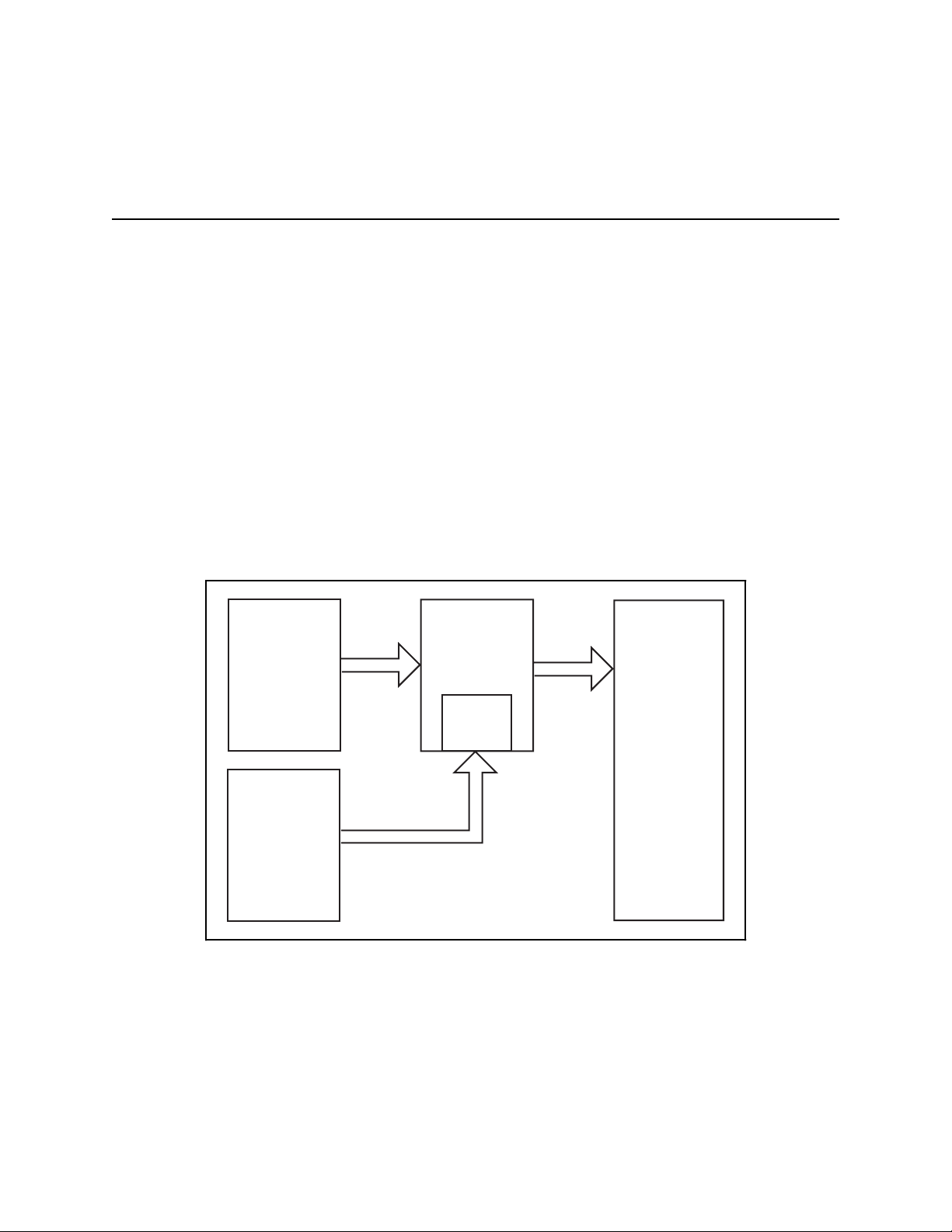
the host computer. Figure 1-1 is a block diagram of the software utilities and libraries that control the
AT-DSP2200. The DSP Library and the low-level memory management and data transfer functions reside and
execute on the board. You can customize the DSP Library to optimize performance, as described in Part 4,
Chapter 2, Getting Started with the NI-DSP Interface Utilities, of this manual. Your application programs and the
Interface Library, however, reside on the host PC.
User
Application
in LabVIEW
VI
Interface
(CIN)
PC AT-DSP2200
Interface
Library
(DSP.DLL)
Figure 1-1. Communication between the PC and the DSP Board
AT or EISA Bus
DSP Software
Onboard Kernel,
DSP Board
Memory
Management,
Data Transfer
Functions
DSP Library
DSP Hardware
CPU
Onboard Memory
NI-DSP SRM for LabVIEW for Windows 1-1 Part 2: Introduction to the NI-DSP Analysis VIs
Page 20

Introduction to the NI-DSP Analysis VIs Part 2
The AT-DSP2200 can process large amounts of data, separately and distinctly from the host PC processor. The
board consists not only of a signal processing chip, but also memory where data that the board processes must
reside. The AT-DSP2200 does not have access to memory locations on the host PC. Therefore, you must download
all data from your application programs to DSP board memory before processing it.
The Interface Library, DSP.DLL, and the Code Interface Node (CIN) interface, which reside on the PC, serve as a
bridge between your application programs in LabVIEW and the DSP software running on the board. When you call
an NI-DSP Analysis VI, the VI passes the parameters to the CIN first, which then passes the parameters to the
Interface Library, DSP.DLL. The Interface Library determines what type of parameters are being passed, decides
how to set up the data in DSP board memory, and then calls the actual functions that will run on the board.
When a function on the DSP board processes data, it assumes the data is resident in DSP board memory. Because
transferring data between the PC and the DSP board slows down processing, none of the NI-DSP Analysis VIs
transfer data back and forth internally except the data transferring VIs. The NI-DSP Analysis VIs process the data
buffers that are already on the board and leave the results on the board.
If the data buffer you want to process using the DSP board is in PC memory, you must copy the data to the DSP
board before you call a function on the DSP board to process the data. To see the results, you must then copy the
data back to the PC. Several special NI-DSP Analysis VIs perform these transfers. For scalars, the NI-DSP
Analysis VIs automatically perform the transfer for you.
The representation of data buffers in the NI-DSP Analysis VIs is not the normal LabVIEW data array representation
because the data buffers indicate the data location on the DSP board instead of the PC address. A special structure,
called a DSP Handle Cluster, represents the data buffer on the DSP board from LabVIEW. The DSP Handle Cluster
is a coded DSP board memory address that indicates where the data buffer is on the DSP board. You must call the
DSP Allocate Memory VI to obtain a valid DSP Handle Cluster. Several VIs can manage the memory on the DSP
board. You can allocate and deallocate memory on the DSP board using these VIs. The next section, Memory
Management and Data Transfer, discusses the VIs used to allocate memory and transfer data buffers to and from the
DSP board.
Memory Management and Data Transfer
This section describes how to manage memory on the DSP board from your LabVIEW application and how to
transfer data between your LabVIEW application and the DSP board.
The NI-DSP for LabVIEW package contains a set of VIs that manage memory space on the DSP board and help
improve data transfers between the DSP board and your application. There are VIs for allocating memory buffers on
the DSP board, for indexing into previously allocated buffers, for deallocating buffers and for copying data between
DSP and LabVIEW. The following VIs, described in greater detail in Part 3 of Chapter 2, NI-DSP Analysis VI
Reference, handle memory management on the DSP board and data transfers between the DSP board and your
LabVIEW application:
• Copy Mem[DSP to DSP]
• Copy Mem[DSP to LV]
• Copy Mem[LV to DSP]
• DSP Allocate Memory
• DSP Free Memory
• DSP Index Memory
• DSP Init Memory
Part 2: Introduction to the NI-DSP Analysis VIs 1-2 NI-DSP SRM for LabVIEW for Windows
Page 21
Part 2 Introduction to the NI-DSP Analysis VIs
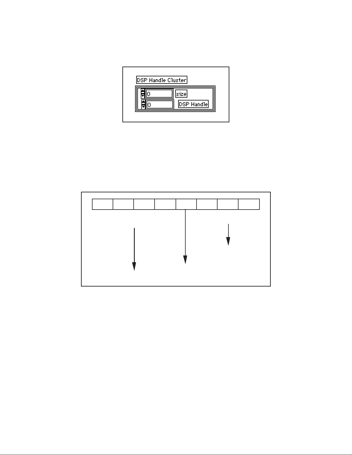
The DSP Allocate Memory VI allocates memory buffers on the DSP board and returns a DSP Handle Cluster, which
has two fields that uniquely describe this buffer–a DSP Handle and a size.
Figure 1-2. DSP Handle Cluster
DSP Handle is a 32-bit integer containing information that indicates the board on which the allocated buffer resides,
and an index into an onboard Memory Look Up Table (MLUT) that holds the actual DSP address of the buffer that
this handle represents. Figure 1-3 shows how a DSP Handle is encoded. The size field holds the number of
elements in this buffer. An element can be 4 bytes (for 32-bit floating-point data or long integer data) or 2 bytes (for
16-bit integer data) depending on the bytes per element selector used in the DSP Allocate Memory VI.
X XXX 3 0 04
Figure 1-3. The Hexadecimal Encoding of a Typical DSP Handle
The first four hexadecimal numbers (upper 16 bits) of the DSP Handle, shown in Figure 1-3, are a special value.
The interface code for a particular function that your application calls decodes these four hexadecimal numbers to
determine if the argument is a valid DSP Handle.
Notes: Do not change the value of a DSP Handle Cluster. Keep in mind that a DSP Handle Cluster is just an entry
of a table that indicates where the data buffer is on the DSP board. If you want to operate on part of the
data in that buffer, use the DSP Index Memory VI or the DSP Subset VI to obtain a new DSP Handle
Cluster to hold the part of the data. Then operate on the new DSP Handle Cluster.
}
Board Number of
Special Code
Owner DSP Board
}
Index into the
MLUT of the
Owner DSP Board
The Memory Look-Up Table (MLUT) has only 128 entries. You can allocate only a total of 128 different
DSP Handle Clusters. Although you might have physical memory on the DSP board, you will get an error
message for not having enough memory if you already have 128 DSP Handle Clusters in use. Free the DSP
Handle Clusters that are not in use. The DSP Init Memory VI will free all DSP Handle Clusters on the
specified DSP board.
NI-DSP SRM for LabVIEW for Windows 1-3 Part 2: Introduction to the NI-DSP Analysis VIs
Page 22
Introduction to the NI-DSP Analysis VIs Part 2
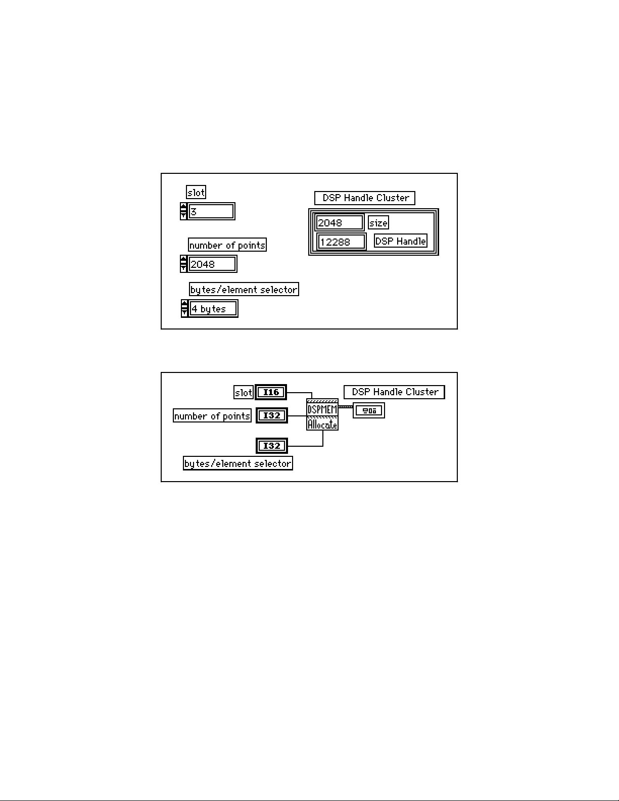
Figures 1-4 and 1-5 show how to allocate a DSP Handle Cluster of 2,048 4-byte-long elements on board 3. The
board number on which the buffer is allocated is important for determining the ownership of the buffer. When
making a VI call, the same DSP board on which the function is to execute must own all of the DSP Handle Clusters
or an error code is returned. Only the DSP Allocate Memory VI and few other VIs that do not have DSP Handle
Clusters as input parameters have a board slot parameter. VIs that have DSP Handle Clusters as input parameters
obtain the board slot information from their own DSP Handle Clusters. All of the DSP Handle Clusters should have
the same slot information, because the DSP VIs assume that all are executing on the same DSP board.
Figure 1-4. Front Panel–An Example of How to Allocate a DSP Handle Cluster
Figure 1-5. Block Diagram–An Example of How to Allocate a DSP Handle Cluster
For all of the NI-DSP Analysis VIs, the array data type is DSP Handle Cluster. Before you call any of these VIs,
call the DSP Allocate Memory VI to obtain a valid DSP Handle Cluster, which you then use as a reference to your
data buffer. The Analysis VIs assume that the data is already on the board and stores the results on the board. If you
want to copy data between the PC and the DSP board, use either the Copy Mem(LV to DSP) VI or the Copy
Mem(DSP to LV) VI to copy data back and forth.
If you use the DSP Allocate Memory VI in your program, use the DSP Free Memory VI to free buffers allocated
when you do not need them any more. The board holds these allocations in memory even after your application has
completed or you exit LabVIEW unless you execute the DSP Init Memory VI or reload the DSP Library. Thus, it is
important to free all buffers your application allocated before you exit the application or you may run out of memory
on the board.
Part 2: Introduction to the NI-DSP Analysis VIs 1-4 NI-DSP SRM for LabVIEW for Windows
Page 23
Part 2 Introduction to the NI-DSP Analysis VIs
Special Features of the NI-DSP Analysis VIs
This section describes the special features of the NI-DSP Analysis VIs that make them different from other
LabVIEW VIs.
• DSP Handle Cluster in/out. The way you specify the output data buffers for NI-DSP Analysis VIs is different
from the way you would specify output data buffers for other LabVIEW VIs. DSP Handle Clusters also
represent all the output data buffers in the NI-DSP Analysis VIs. To use valid DSP Handle Clusters for the
NI-DSP VI output data buffers, you must use the DSP Allocate Memory VI to obtain the DSP Handle Clusters
before you use them. Supply all of the output DSP Handle Clusters as inputs to tell the DSP board where the
output buffers are. Every output DSP Handle Cluster is identical to the corresponding input DSP Handle
Cluster. The two DSP Handle Clusters are internally connected. The output is an indicator. The input is a
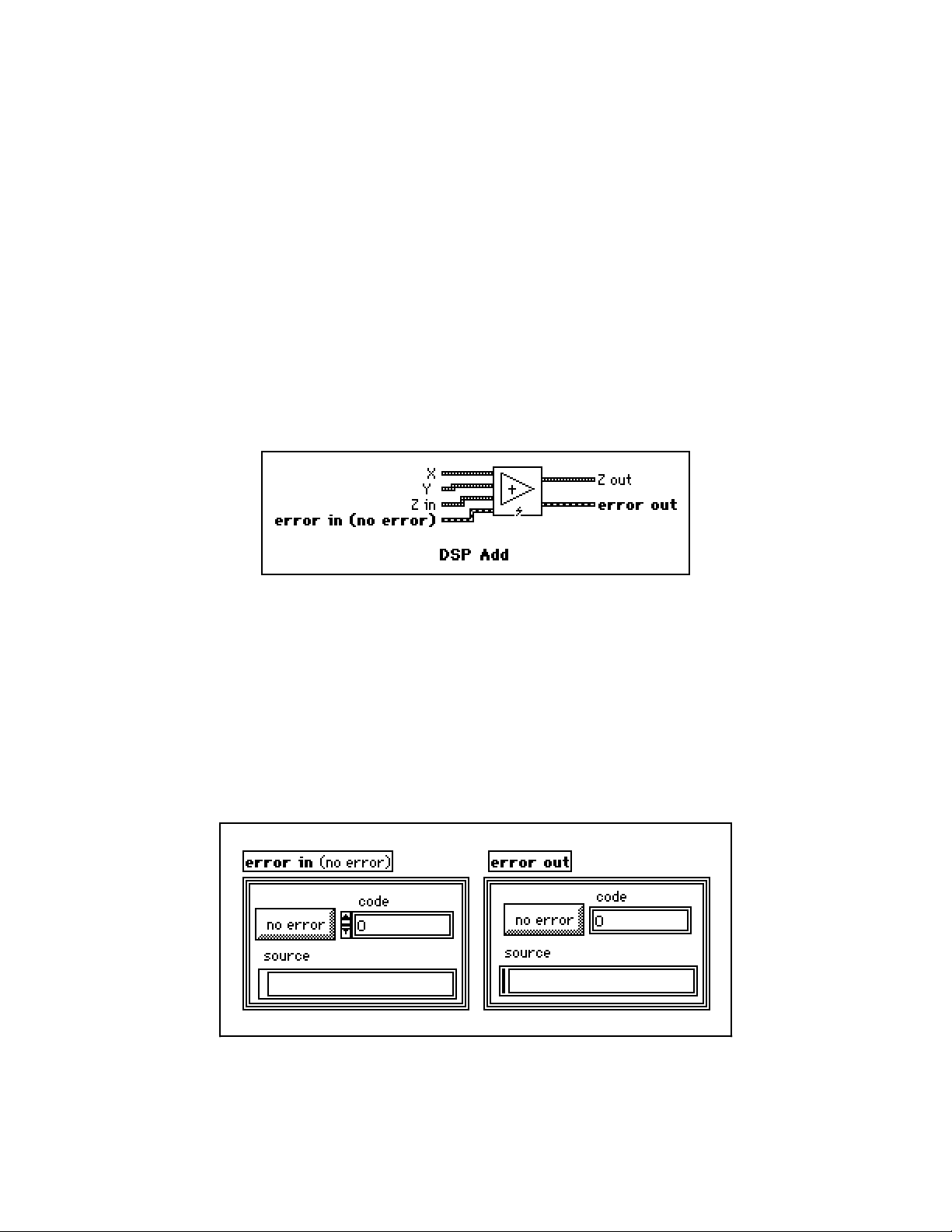
control. For example, in the DSP Add VI, shown in Figure 1-6, Z is the DSP Handle Cluster that indicates
where to store the results. You use Z in to connect to a valid DSP Handle Cluster that you previously allocated.
Z in tells the DSP board where the results will be stored. Z out is the location where the results have already
been stored. Because Z in and Z out are the same DSP Handle Cluster, you need to free only one of them when
you want to deallocate their DSP board buffer.
Figure 1-6. DSP Add VI
All of the controls and indicators in the NI-DSP Analysis VIs follow the Z in, Z out naming convention and
work in the same way as previously described in the example, except for the error in/error out cluster.
• Error Handling. All of the NI-DSP Analysis VIs have an error input and an error output for managing and
reporting errors. The error in/error out cluster used by the NI-DSP VIs and many other high-level I/O
operations is a cluster containing a Boolean indicating whether the data should be treated as an error, a 32-bit
error code, and a descriptive string that usually contains the name of the source of the error. The error in/error
out cluster is shown in Figure 1-7.
Figure 1-7. The error in/error out Cluster
NI-DSP SRM for LabVIEW for Windows 1-5 Part 2: Introduction to the NI-DSP Analysis VIs
Page 24
Introduction to the NI-DSP Analysis VIs Part 2
The error in/error out cluster contains the following elements:
The boolean value is true if an error occurred, false if no error occurred.
code is the error code.
source is the source of the error. If an error occurs during execution, the VI sets source to the name
of the VI that produced the error.
Every VI checks error in first. If there is an error, the VI does not execute any DSP code but simply passes the
contents of error in to the error out cluster. If there is no error, the VI executes. One advantage of this error
in/error out design is that you can connect several I/O operations together so that, if an error occurs, subsequent VIs
do not perform undesired actions. DSP Free Memory will execute even if an error occurs. This ensures that
allocated buffers are freed even if an error occurred.
Another advantage of this error in/error out design is that you can establish the order of a set of operations, even if
there is no other data flow between the operations. Connecting the error out of the first VI to the error in of the
second VI establishes data flow and therefore execution order. You could do the same thing with a Sequence
structure, but with the error in/error out design, you can establish the order with all of the operations at the top level
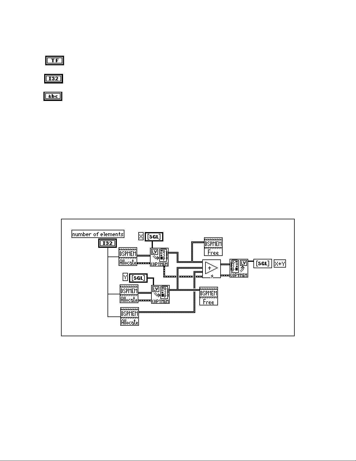
of the block diagram. For example, in Figure 1-8, you allocate DSP Handle Clusters X and Y as inputs, and you want
to free X and Y after the DSP Add VI has been executed. If you simply connect X to the DSP Free Memory VI as
shown in Figure 1-8, there is no sequential order between the DSP Add VI and the DSP Free Memory VI. If the DSP
Free Memory VI executes first, the DSP Add VI will receive an invalid handle because that DSP Handle Cluster was
deallocated.
Figure 1-8. An Example That Does Not Use error in/error out
for Sequencing VIs
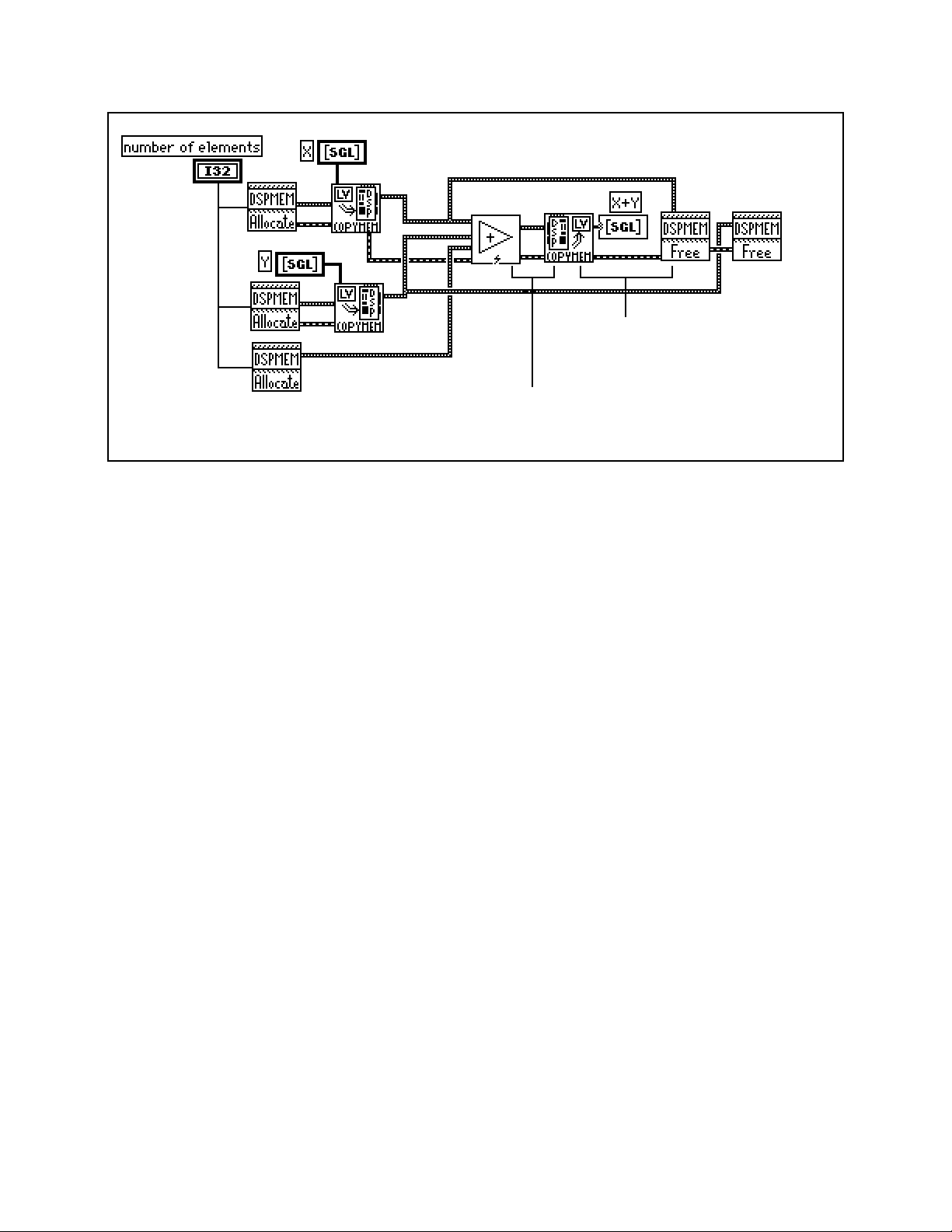
If you connect the VIs as shown Figure 1-9 instead, you ensure that the DSP Add VI executes before the DSP Free
Memory VI.
Part 2: Introduction to the NI-DSP Analysis VIs 1-6 NI-DSP SRM for LabVIEW for Windows
Page 25
Part 2 Introduction to the NI-DSP Analysis VIs
error out of the Copy Mem(LV to DSP) VI is
connected to the error in of the DSP Free
Memory VI
error out of the DSP Add VI is
connected to the error in of the
Copy Mem(LV to DSP) VI
Figure 1-9. An Example of Using the error in/error out Cluster for Sequential VI Execution
For more information about the error in/error out cluster, refer to Chapter 2, Error Handler VIs, in the LabVIEW
Utility VI Reference Manual.
Hints for Improving the Execution Speed on the DSP Board
Check each of the following things to maximize your DSP board performance:
• Allocate as many of the DSP Handle Clusters as you can before you operate on the data. Keep all data on the
DSP board until you finish all of the processing. Reduce the number of data transfers between the DSP board
and the PC as much as possible. The functions that run on the DSP board are very fast, but transferring data
between the DSP board and the PC and memory allocation slows the total processing performance.
• Use the error in/error out cluster for sequencing VI execution. Be sure all of your VIs run in the correct
sequence. Use the error in/error out cluster to propagate the errors. If an error occurs, you can tell where the
error happens. You can use the LabVIEW error handler VIs in the Utility option of the Functions menu to
obtain pop-up error messages. Refer to the LabVIEW Utility VI Reference Manual for more information about
these VIs.
• Many analysis routines on the DSP board can be performed in place; that is, the input and output array can be
the same array. This is very important to remember when you are processing large amounts of data. Large
32-bit floating-point arrays consume a lot of memory. If the results you want do not require that you keep the
original array or an intermediate array of data, perform analysis operations in place whenever possible. For
example, use the same DSP Handle Cluster for the input and output data buffers in your diagram in LabVIEW.
This will save your DSP board memory.
• Several intermediate-level data acquisition VIs work with DSP Handle Clusters. These VIs can acquire data
and leave it on the board. You can use the NI-DSP Analysis VIs to operate on this data and then copy the
processed results back to the PC. In this way, you dramatically reduce the data transfer overhead between the
PC and the DSP board, and improve the overall performance. For more information about these data
acquisition VIs, refer to the LabVIEW Data Acquisition VI Reference Manual. An example that shows you how
to use a DSP Handle Cluster to acquire data and process this data on the DSP board can be found in the
DSP2200 subdirectory of the EXAMPLES subdirectory of your LabVIEW directory.
NI-DSP SRM for LabVIEW for Windows 1-7 Part 2: Introduction to the NI-DSP Analysis VIs
Page 26
Introduction to the NI-DSP Analysis VIs Part 2
An Example of Using NI-DSP Analysis VIs
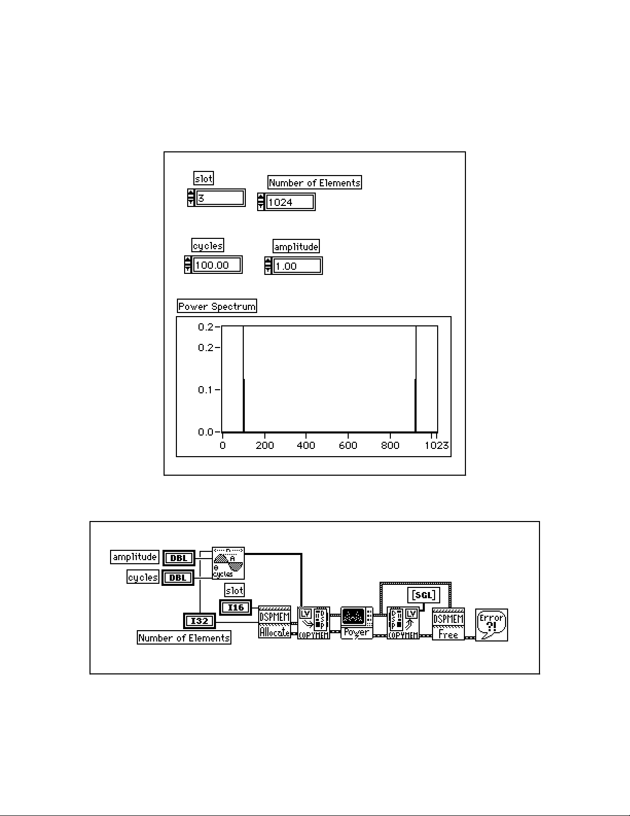
Figures 1-10 and 1-11 show the front panel and block diagram, respectively, of an example using NI-DSP Analysis
VIs.
Figure 1-10. Front Panel–An Example of Using NI-DSP Analysis VIs
Figure 1-11. Block Diagram–An Example of Using NI-DSP Analysis VIs
Part 2: Introduction to the NI-DSP Analysis VIs 1-8 NI-DSP SRM for LabVIEW for Windows
Page 27

Part 2 Introduction to the NI-DSP Analysis VIs
This example shows you how to obtain the power spectrum of a sine wave signal. First, generate a sine wave that
you want to analyze using the LabVIEW Analysis VIs, then use the Copy Mem(LV to DSP) VI to copy the data of
this sine signal to the DSP board. Before you copy the data, you must call the DSP Allocate Memory VI to allocate
a DSP Handle Cluster that reserves a data buffer on the DSP board. Connect this DSP Handle Cluster to the
destination in terminal of the Copy Mem(LV to DSP) VI to indicate where the data will be stored on the DSP
board. After the data is copied to the DSP board, call the DSP Power Spectrum VI to perform a power spectrum on
the data. After you finish the analysis, the results are stored in the data buffer indicated by the DSP Handle Cluster
you previously allocated. If you want to see the results, call the Copy Mem(DSP to LV) VI to copy data back to
LabVIEW. Figure 1-10 shows the power spectrum of a sine wave. The last step is to call the DSP Free Memory VI
to free the DSP Handle Cluster that you allocated. This example connects all of the error out clusters of the
previous VIs to the error in clusters of the subsequent VIs to establish the proper sequence and to pass through an
error, should it occur, without executing the rest of the VIs.
NI-DSP SRM for LabVIEW for Windows 1-9 Part 2: Introduction to the NI-DSP Analysis VIs
Page 28

Chapter 1 NI-DSP Analysis VI Reference Overview
This chapter contains an overview of the NI-DSP Analysis VIs and includes a list of the VIs. This chapter describes
how the NI-DSP Analysis VIs are organized and how to access them.
The NI-DSP Analysis VI Overview
The NI-DSP Analysis VIs are a set of high-performance VIs that efficiently process large blocks of numerical data
and perform numerically intensive computations. The NI-DSP Analysis VIs include numerical analysis, signal
generation, digital signal processing, digital filtering, and windowing operations that are suitable for simulation,
modeling, and sophisticated data processing.
The NI-DSP Analysis VIs are presented in alphabetical order in Chapter 2, NI-DSP Analysis VI Reference.
Table 1-1 lists these VIs by group.
Table 1-1. The NI-DSP Analysis VI Groups
Signal Generation
DSP Sine Pattern
DSP Pulse Pattern
DSP Impulse Pattern
DSP Impulse Train Pattern
DSP Ramp Pattern
DSP Sinc Pattern
DSP Square Pattern
DSP Triangle Pattern
DSP Triangular Train
DSP Sawtooth Pattern
DSP Uniform White Noise
DSP Random Pattern
DSP Gaussian White Noise
Frequency Domain
DSP ReFFT
DSP Complex FFT
DSP Inverse FFT
DSP Power Spectrum
DSP Cross Power
DSP FHT
DSP Inverse FHT
DSP Zero Padder
Time Domain
DSP Convolution
DSP Deconvolution
DSP Correlation
DSP Decimate
DSP Derivative
DSP Integral
(continues)
NI-DSP SRM for LabVIEW for Windows 1-1 Part 3: NI-DSP Function Reference
Page 29

NI-DSP Analysis VI Reference Overview Chapter 1
Table 1-1. The NI-DSP Analysis VI Groups (Continued)
Filters
DSP Butterworth Coefficients
DSP Chebyshev Coefficients
DSP Inverse Chebyshev Coeff
DSP Elliptic Coefficients
DSP IIR Filter
DSP Equi-Ripple LowPass
DSP Equi-Ripple HighPass
DSP Equi-Ripple BandPass
DSP Equi-Ripple BandStop
DSP Parks-McClellan
DSP Median Filter
Windows
DSP Blackman Window
DSP Exact Blackman Window
DSP Blackman Harris Window
DSP Hanning Window
DSP Hamming Window
DSP Flat Top Window
DSP General Cosine Window
DSP Exponential Window
DSP Force Window
DSP Kaiser-Bessel Window
DSP Triangular Window
Array Functions
DSP Add
DSP Subtract
DSP Multiply
DSP Divide
DSP Absolute
DSP Square Root
DSP Product
DSP Sum
DSP Log
DSP Clip
DSP Reverse
DSP Shift
DSP Sort
DSP Linear Evaluation
DSP Max & Min
DSP Polynomial Evaluation
DSP Subset
DSP Set
DSP Unwrap
DSP Polar to Rectangular
DSP Rectangular to Polar
Memory Management
DSP Allocate Memory
Copy Mem(LV to DSP)
Copy Mem(DSP to LV)
Copy Mem(DSP to DSP)
DSP Free Memory
DSP Index Memory
DSP Init Memory
Part 3: NI-DSP Function Reference 1-2 NI-DSP SRM for LabVIEW for Windows
Page 30
Chapter 1 NI-DSP Analysis VI Reference Overview
Table 1-1. The NI-DSP Analysis VI Groups (Continued)
Utility Functions
DSP Reset
DSP Load
DSP Start
DSP Timeout
DSP Custom
DSP DMA Copy(DSP to LV)
DSP DMA Copy(LV to DSP)
DSP Handle to Address
Analysis VI Organization
After installation, the NI-DSP Analysis VIs reside in the following VI library files (LabVIEW .LLB files) within
the DSP2200 option:
• Signal Generation contains VIs that generate digital patterns.
• Frequency Domain contains VIs that perform frequency domain transformations, frequency domain analysis,
and other transforms such as the Hartley transform.
• Time Domain contains VIs that perform direct time series analysis of signals.
• Filters contains VIs that perform IIR and FIR filtering functions.
• Windows contains VIs that perform smoothing windowing.
• Array contains VIs that perform arithmetic operations on arrays.
• Memory Management contains VIs to perform allocating, indexing, copying, and freeing memory on the
AT-DSP2200 board.
• Utility contains VIs for controlling the operation of the AT-DSP2200 board.
After installation, the eight analysis VI libraries appear in the Functions menu in the order shown in the preceding
list under the DSP2200 option. You can reorganize the folders and the VIs to suit your needs and applications.
Accessing the NI-DSP Analysis VIs
To access the analysis VIs from the block diagram window, choose DSP2200 from the Functions menu as shown in
Figure 1-1, proceed through the hierarchical menus, and select the VI you want. The icon corresponding to that VI
appears in the block diagram and is ready to be wired.
NI-DSP SRM for LabVIEW for Windows 1-3 Part 3: NI-DSP Function Reference
Page 31
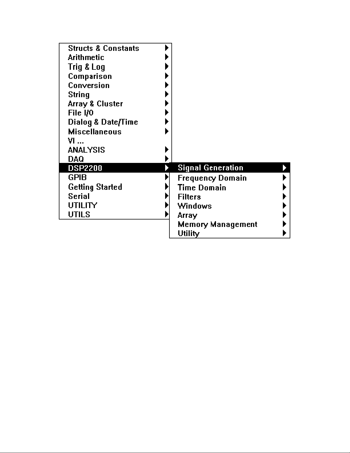
NI-DSP Analysis VI Reference Overview Chapter 1
Figure 1-1. Choosing DSP2200 from the Functions Menu
About the Fast Fourier Transform (FFT)
The VIs in the Frequency Domain group are based upon the discrete implementation and optimization of the Fourier
Transform integral. The Discrete Fourier Transform (DFT) of a complex sequence X containing n elements is
obtained using the following formula:
n-1
Y[i] = ∑ X[k] * exp (-j2π ik / n), for i = 0, 1, …, n-1
k=0
where Y[i] is the ith element of the DFT of X and j = √-1.
The DFT of X also results in a complex sequence Y of n elements. Similarly, the Inverse Discrete Fourier
Transform (IDFT) of a complex sequence Y containing n elements is obtained using the following formula:
X[i] = (1/n) ∑ Y[k] * exp (j2π ik / n), for i = 0, 1, …, n-1
where X[i] is the ith element of the IDFT of Y and j = √-1.
n-1
k=0
Part 3: NI-DSP Function Reference 1-4 NI-DSP SRM for LabVIEW for Windows
Page 32

Chapter 1 NI-DSP Analysis VI Reference Overview
The discrete implementation of the DFT is a numerically intense process. However, it is possible to implement a
fast algorithm when the size of the sequence is a power of two. These algorithms are known as FFTs, and can be
found in many introductory digital signal processing (DSP) texts.
The resulting complex FFT sequence has the conventional DSP format as described in this section.
If there are n number of elements in the complex sequence and k = n/2, then the output of the FFT is organized as
follows:
Y[0] DC component
Y[1] Positive first harmonic
Y[2] Positive second harmonic
: :
Y[k-1] Positive k-1 harmonic
Y[k] Nyquist frequency
Y[k+1] Negative k-1 harmonic
: :
Y[n-2] Negative second harmonic
Y[n-1] Negative first harmonic
The following conventions and restrictions apply to the VIs in the Frequency Domain folder:
• All arrays must be a power of two: n = 2m, m = 1, 2, 3, …, 24 (limited by onboard memory).
• Complex sequences are manipulated using two arrays. One array represents the real elements. The other array
represents the imaginary elements.
The following notation is used to describe the FFT operations performed in the Frequency Domain class:
• Y = FFT {X}, the sequence Y is the FFT of the sequence X.
• Y = FFT-1 {X}, the sequence Y is the inverse FFT of the sequence X.
X is usually a complex array but can be treated as a real array.
About Filtering
All of the VIs in the Filters group are digital filters that can be represented by the computational algorithm that best
describes the relationship between the input and output discrete time sequences. This computational algorithm is
referred to as the Linear Constant Coefficient Difference Equation. This equation relates the input and output by the
basic operations of addition, delay and multiplication. The following equation relates the input and output
sequences x and y, respectively at the discrete time instant n:
i = N-1 i = M-1
a(0)*y(n) = ∑ (x[n-i]*b(i)) - ∑ (y[n-i]*a(i)) (a)
where :
x is the discrete time input signal to the system represented by the filter
y is the discrete time output signal of the system represented by the filter
a is the set of coefficients applied to the input in the linear difference equation and represent the
multiplication factors for delays. The equation suggests that there are N such coefficients.
b is the set of coefficients applied to the output in the linear difference equation and represent the
multiplication factors for delays. The equation suggests that there are M such coefficients.
i = 0 i = 1
NI-DSP SRM for LabVIEW for Windows 1-5 Part 3: NI-DSP Function Reference
Page 33

NI-DSP Analysis VI Reference Overview Chapter 1
The set of coefficients a and b are often referred to as the numerator and denominator coefficients, respectively.
Another common way to refer to them is as the feedforward and feedback coefficients. This is due to the
mathematical derivation that led to equation a. Refer to Discrete-Time Signal Processing by Oppenheim and
Schafer for more information. Another frequent assumption is that a(0)=1.0. For example, let us assume M = 4,
N = 4 and n = 2. Using the filtering equation produces:
a(0)*y(2) = b(0)*x(2) + b(1)*x(1) + b(2)* x(0) + b(3)* x(-1) - a(1)*y(1) - a(2)*y(0) - a(3)*y(-1) (b)
The filtering equation suggests that in order to compute the value of the output at n = 2, you not only need the
coefficients that represent the filter that is producing this output sequence, but also the value of the current input and
output, the values of the input and output one time unit ago, the values of the input and output two time units ago,
and the values of the input and output three time units ago. You need some “history” about the previous outputs of
the filter as well as the previous inputs to the filter. The amount of history (number of previous output and input
samples) depends on the lengths of the arrays a and b (filter coefficients arrays).
At time n = 0, it is important to note that the filtering equation becomes:
a(0)*y(0) = b(0)*x(0) + b(1)*x(-1) + b(2)* x(-2) + b(3)* x(-3) - a(1)*y(-1) - a(2)*y(-2) - a(3)*y(-3) (c)
Thus, for the function filter to properly operate as of time n = 0, you need to supply some history about previous
behavior. The filter function then updates the history as time goes on, keeping track of previous input values and
corresponding outputs. This history, at time n = 0, is referred to as the initial conditions on the input and output of
the filter.
Digital filters fall into two classes–Infinite Impulse Response filters (IIR filters) and Finite Impulse Response filters
(FIR filters). Notice that IIR filters are represented by equation (a) while the FIR filters can be represented by the
same equation provided all a's are zero except for a(0) as shown in the following equation:
i = N
a(0)*y(n) = ∑ (x[n-i]*b(i)) (d)
The NI-DSP Analysis VIs have a set of VIs that implement IIR and FIR filters. Because all digital filters are
approximations of their analog design counterparts, there are several techniques for designing a digital filter.
For the IIR filter design, the NI-DSP Analysis VIs have four approaches representing four different techniques of
obtaining digital filter specifications (coefficients to equation (a))–Butterworth, Chebyshev, inverse Chebyshev, and
elliptic techniques. With each design technique, you can obtain the coefficients for lowpass, highpass, bandpass,
and bandstop filters from the respective NI-DSP Analysis VIs.
For the FIR filters, the NI-DSP Analysis VIs allow the design of a multiband FIR linear phase filter using the ParksMcClellan algorithm. The frequency response in each band has equal ripples that can be adjusted by a weighting
factor. For more information, please refer to Digital Filter Design by Parks and Burrus, or "A Computer Program
for Designing Optimum FIR Linear Phase Digital Filters," by McClellan, Parks, and Rabiner.
The IIR VIs generate filter coefficients that represent the a's and b's in the equations a and b. No filtering is actually
performed. The IIR filter design coefficients all have a(0) = 1.0. You can use the general-purpose VI that accepts
filter coefficients, initial conditions on the input and output sequences, and an input sequence to filter any of the
filter specifications. This VI filters the input sequence and provides the final conditions on the output and input of
the filter.
i = 0
About Windowing
Almost every application requires you to use finite length signals. This requires that continuous signals be
truncated, using a process called windowing.
Part 3: NI-DSP Function Reference 1-6 NI-DSP SRM for LabVIEW for Windows
Page 34

Chapter 1 NI-DSP Analysis VI Reference Overview
m
g
The simplest window is a rectangular window. Because this window requires no special effort it is commonly
referred to as the no window option. Remember, however, that a discrete signal and its spectrum is always affected
by a window. Let x[n] be a digitized time-domain waveform that has a finite length of n. w[n] is a window
sequence of n points. The windowed output is calculated as follows:
y[i] = x[i] * w[i] (1)
If X, Y, and W are the spectra of x, y, and w, respectively, the time-domain multiplication in formula 1 is equivalent
to the convolution shown as follows:
Y[k] = X[k] Θ W[k]. (2)
Convolving with the window spectrum always distorts the original signal spectrum in some way. A window
spectrum consists of a big mainlobe and several sidelobes.
The mainlobe is the primary cause of lost frequency resolution. When two signal spectrum lines are too close to
each other, they may fall in the width of the mainlobe, causing the output of the windowed signal spectrum to have
only one spectrum line. Use a window with a narrower mainlobe to reduce the loss of frequency resolution. It has
been shown that a rectangular window has the narrowest mainlobe, so that it provides the best frequency resolution.
The sidelobes of a window function affect frequency leakage. A signal spectrum line will leak into the adjacent
spectrum if the sidelobes are large. Once again, the leakage results from the convolution process. Select a window
with relatively smaller sidelobes to reduce spectral leakage. Unfortunately, a narrower mainlobe and smaller
sidelobes are mutually exclusive. For this reason, selecting a window function is application dependent. An
example of a windowed spectrum in the continuous case is shown in Figure 1-2.
*
Signal Spectru
Windowed Si
Figure 1-2. Spectral Leakage Demonstrated Using Convolution
The original signal spectrum is convolved with the window spectrum and the output is a smeared version of the
original signal spectrum. In this example, you can still see four distinctive peaks from the original signal, but each
peak is smeared and the frequency leakage effect is clear.
nal Spectrum
Window Spectrum
NI-DSP SRM for LabVIEW for Windows 1-7 Part 3: NI-DSP Function Reference
Page 35

NI-DSP Analysis VI Reference Overview Chapter 1
Window definitions used in National Instruments analysis libraries are designed in such a way that the window
operations in the time domain are exactly equivalent to the operations of the same window in the frequency domain.
To meet this requirement, the windows are not symmetrical in the time domain, that is:
w[0] ≠ w[N-1] (3)
where N is the window length. They are usually symmetrical in the frequency domain, however. For example, the
Hamming window definition uses the formula:
w[i] = 0.54 - 0.46 cos(2πi/N) (4)
Other manufacturers may use a slightly different definition, such as:
w[i] = 0.54 - 0.46 cos(2πi/N-1) (5)
The difference is small if N is large.
Formula 4 is not symmetrical in the time domain, but it ensures that the time domain windowing is equivalent to the
frequency domain windowing. If you want to have a perfectly symmetrical sequence in the time domain, you must
write your own windowing function using formula 5.
The choice of a window depends on the application. For most applications, the Hamming or Hanning windows
deliver good performance.
Part 3: NI-DSP Function Reference 1-8 NI-DSP SRM for LabVIEW for Windows
Page 36

Chapter 2 NI-DSP Analysis VI Reference
This chapter contains a brief explanation of each NI-DSP Analysis VI . The VIs are arranged alphabetically.
Copy Mem(DSP to DSP)
Copies a buffer of data from the Source
buffer on the DSP board that is referred to
by a DSP Handle Cluster to the destination
buffer on the DSP board, which is referred
to by another DSP Handle Cluster. Source
and destination buffers should be on the
same DSP board.
To copy data correctly from one DSP
buffer to another DSP buffer, you must set the data type to the appropriate type to indicate what kind of data is on
the DSP board. The VI has three data types–32-bit floating-point data, 16-bit short integer data, and 32-bit long
integer data.
Source is a DSP Handle Cluster that indicates the memory buffer on the DSP board that contains the
data that you want to copy to the destination.
data type indicates the type of data that Source contains. The VI has three data types:
0: 32-bit floating-point data.
1: 16-bit short integer data.
2: 32-bit long integer data.
data type defaults to 32-bit floating-point data.
Destination in is a DSP Handle Cluster that indicates the destination memory buffer on the DSP board
that will contain the data copied from source buffer.
Destination out is a DSP Handle Cluster that is identical to the Destination in, but with the source
buffer data already copied to the memory buffer on the DSP board.
error in (no error) contains the error information from a previous VI. If an error occurs, it is passed out
error out and no other calls are made.
error out contains the error information for this call.
NI-DSP SRM for LabVIEW for Windows 2-1 Part 3: NI-DSP Function Reference
Page 37

NI-DSP Analysis VI Reference Chapter 2
Copy Mem(DSP to LV)
Copies an entire or partial buffer
of data according to the
entire/partial copy selector from
the Source buffer on the DSP
board that is referred to by a DSP
Handle Cluster to the destination
buffer in LabVIEW.
To copy data correctly from the
DSP board to LabVIEW, you
must indicate what type of data is
stored in the Source buffer on the DSP board. You must set the destination type to the appropriate type and wire to
the corresponding destination terminal. The VI has three destination types–float (32-bit), short (16-bit), and long
(32-bit). To copy different types of data, you must wire to the appropriate destination terminal that corresponds to
the destination type you choose. Remember, you must wire only one kind of destination terminal.
If you set the entire/partial copy selector to entire copy, all the data in the Source buffer will be copied back to the
destination without considering the values of offset and size. Otherwise, only the number of size the data in the
Source buffer, starting from the offset, will be copied back to the destination.
entire/partial copy selector has two types: entire copy and partial copy. It defaults to entire copy.
0: entire copy.
1: partial copy.
Source is a DSP Handle Cluster that indicates the memory buffer on the DSP board which contains the
data that you want copy to the destination in LabVIEW.
destination type indicates the type of the destination data on the DSP board. It has three options:
0: 32-bit floating-point.
1: 16-bit short integer.
2: 32-bit long integer.
destination type defaults to 32-bit floating point.
offset indicates where to start to copy data from the Source buffer on the DSP board to the destination
buffer in the LabVIEW. offset defaults to 0. This parameter is ignored when entire/partial copy
selector is set to entire copy.
size indicates how much data to copy from the Source buffer on the DSP board to the destination buffer
in LabVIEW. size defaults to 0. If offset plus size is greater than the number of elements in the Source
buffer, the VI returns an error. This parameter is ignored when entire/partial copy selector is set to
entire copy.
destination(float) is the terminal to which you should wire the destination buffer if the data you want to
copy is 32-bit floating-point data array.
destination(long) is the terminal to which you should wire the destination buffer if the data you want to
copy is 32-bit long data array.
destination(short) is the terminal to which you should wire the destination buffer if the data you want to
copy is 16-bit short data array.
error in (no error) contains the error information from a previous VI. If an error occurs, it is passed out
error out and no other calls are made.
error out contains the error information for this call.
Part 3: NI-DSP Function Reference 2-2 NI-DSP SRM for LabVIEW for Windows
Page 38

NI-DSP Analysis VI Reference Chapter 2
Copy Mem(LV to DSP)
Copies a buffer of data from the source
buffer in LabVIEW to the destination
buffer on the DSP board, which is referred
to by a DSP Handle Cluster.
The source buffer can contain one of three
kinds of data–float (32-bit), short
(16-bit), and long (32-bit). To copy
different types of data, you must wire to the
appropriate source terminal. You must
wire only one kind of source terminal. The
destination buffer must be large enough to contain all of the data from the source buffer.
source(float) is the terminal to which you should wire the source buffer if the data you want to copy is
32-bit floating point data array.
source(long) is the terminal to which you should wire the source buffer if the data you want to copy is
32-bit long data array.
source(short) is the terminal to which you should wire the source buffer if the data you want to copy is
16-bit short data array.
Destination in is a DSP Handle Cluster that indicates the destination memory buffer on the DSP board
that will contain the data copied from the LabVIEW source buffer.
Destination out is a DSP Handle Cluster that is identical to Destination in, but with the source buffer
data already copied to the memory buffer on the DSP board.
error in (no error) contains the error information from a previous VI. If an error occurs, it is passed out
error out and no other calls are made.
error out contains the error information for this call.
Part 3: NI-DSP Function Reference 2-3 NI-DSP SRM for LabVIEW for Windows
Page 39

Chapter 2 NI-DSP Analysis VI Reference
DSP Absolute
Find the absolute value of input array X. The i
element of the output array Y is obtained using
the following formula:
Y(i) = |X(i) |.
for i = 0, 1, 2, … , n-1
where n is the number of elements in X.
X is a DSP Handle Cluster that indicates the memory buffer on the DSP board that contains the input
signal array X.
Y in is a DSP Handle Cluster that indicates the memory buffer on the DSP board that will contain the
absolute results of X(i).
Y out is a DSP Handle Cluster that is identical to Y in, but with the absolute results already stored in the
memory buffer on the DSP board.
error in (no error) contains the error information from a previous VI. If an error occurs, it is passed out
error out and no other calls are made.
error out contains the error information for this call.
The operation can be performed in place; that is, the input and output arrays can be the same DSP Handle Cluster.
th
NI-DSP SRM for LabVIEW for Windows 2-4 Part 3: NI-DSP Function Reference
Page 40
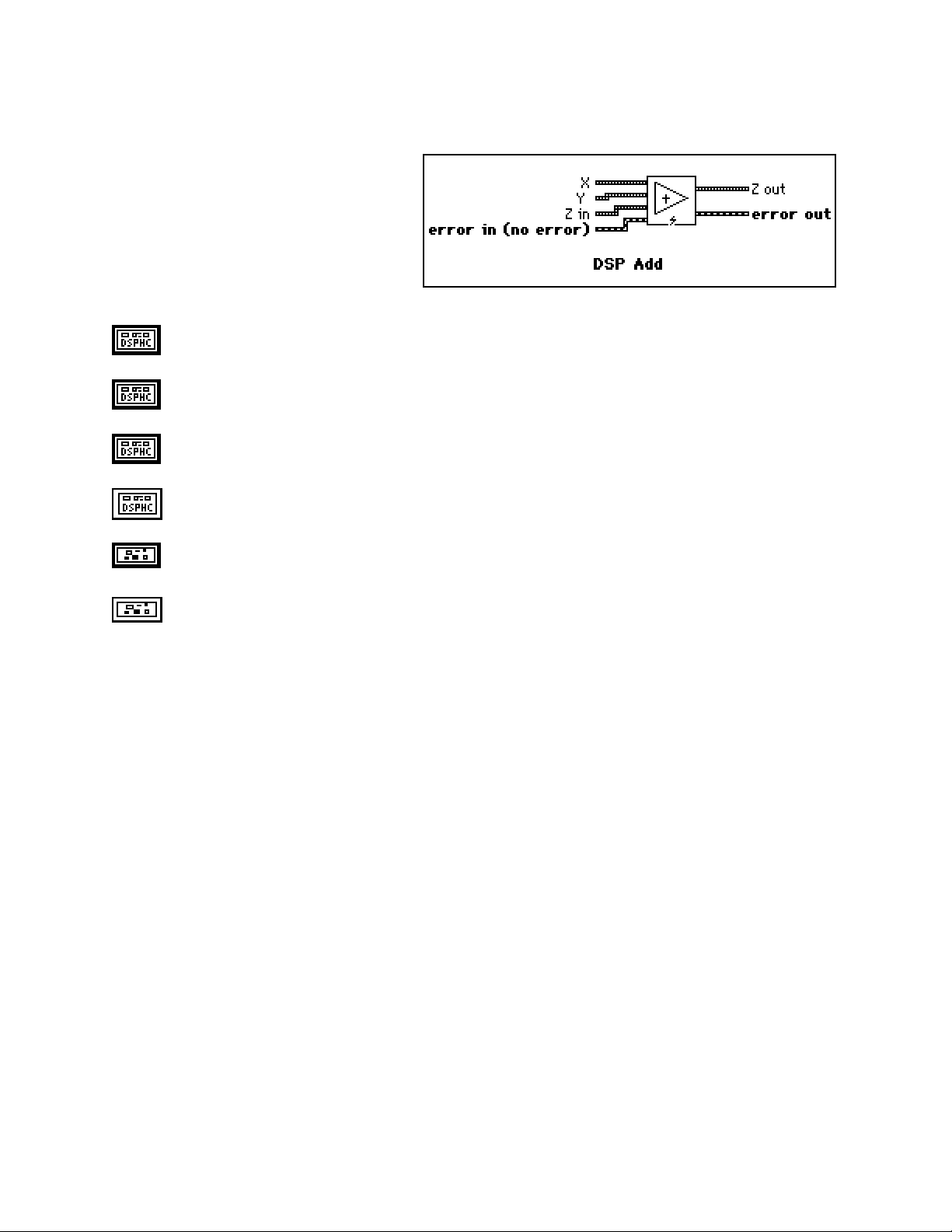
NI-DSP Analysis VI Reference Chapter 2
DSP Add
Add array X to array Y. The ith element of the
output array Z is obtained using the following
formula:
Z(i) = X(i) + Y(i).
for i = 0, 1, 2, … , n-1
where n is the smaller number of elements in X and Y.
X is a DSP Handle Cluster that indicates the memory buffer on the DSP board that contains the input
signal array X.
Y is a DSP Handle Cluster that indicates the memory buffer on the DSP board that contains the input
signal array Y.
Z in is a DSP Handle Cluster that indicates the memory buffer on the DSP board that will contain the
results of X(i) + Y(i).
Z out is a DSP Handle Cluster that is identical to Z in, but with the added results already stored in the
memory buffer on the DSP board.
error in (no error) contains the error information from a previous VI. If an error occurs, it is passed out
error out and no other calls are made.
error out contains the error information for this call.
The operation can be performed in place; that is, the input and output arrays can be the same DSP Handle Cluster.
Part 3: NI-DSP Function Reference 2-5 NI-DSP SRM for LabVIEW for Windows
Page 41
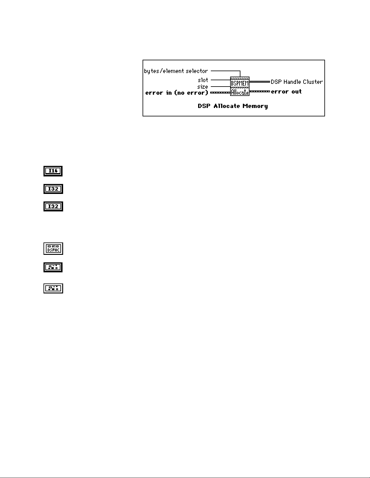
Chapter 2 NI-DSP Analysis VI Reference
DSP Allocate Memory
Allocates a block of memory buffer on
the DSP board specified by slot and
returns a DSP Handle Cluster that
contains the coded DSP board memory
and the number of elements in this
buffer.
The number of bytes allocated for this
buffer depends on size and
bytes/element selector. If bytes/element selector selects 4 bytes, then the number of bytes = size*4. If
bytes/element selector selects 2 bytes, then the number of bytes = size*2.
The allocation routines on the board assure alignment to the nearest 4-byte boundary ≥ number of bytes to guarantee
memory alignment on 4-byte addresses. For example, if you request to allocate a buffer of size 1,022 or 1,024 bytes,
the allocation routines allocate 1,024 bytes in both cases.
slot is the board ID number. slot defaults to 3.
size is the number of elements to allocate for this buffer. size defaults to 0.
bytes/element selector specifies the number of bytes per element. It has two options:
0: 4 bytes.
1: 2 bytes.
bytes/element selector defaults to 4 bytes.
DSP Handle Cluster indicates the allocated memory buffer on the DSP board.
error in (no error) contains the error information from a previous VI. If an error occurs, it is passed out
error out and no other calls are made.
error out contains the error information for this call.
NI-DSP SRM for LabVIEW for Windows 2-6 Part 3: NI-DSP Function Reference
Page 42
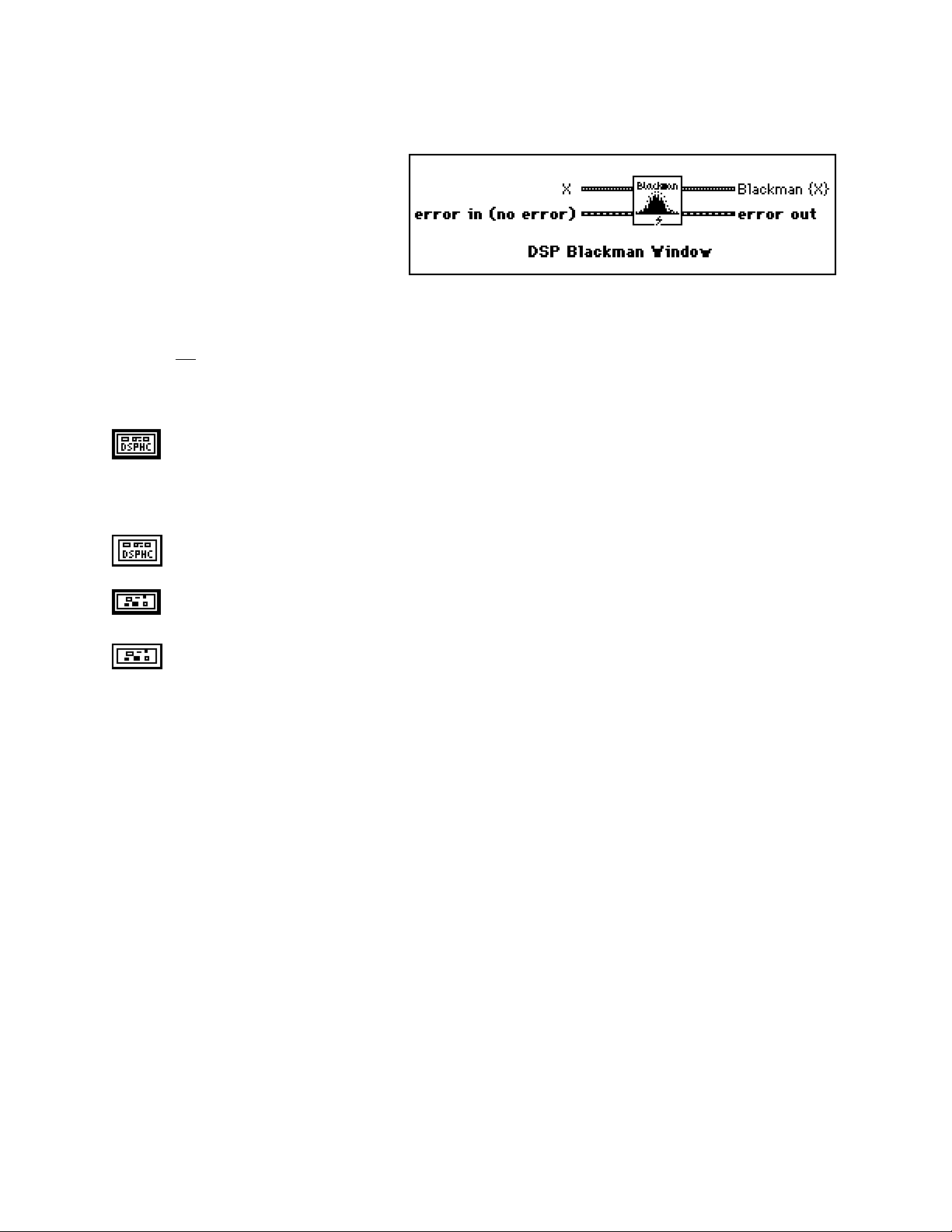
NI-DSP Analysis VI Reference Chapter 2
DSP Blackman Window
Applies a Blackman window to the input
sequence X. If Y represents the output
sequence Blackman{X}, the elements of Y
are obtained from the following formula:
yi = xi [0.42 - 0.50 cos(w)
+ 0.08 cos(2w)]
for i = 0, 1, 2, … , n-1 ,
2πi
w =
where n is the number of elements in X.
,
n
X is a DSP Handle Cluster that indicates the memory buffer on the DSP board that contains the input
signal array.
Note: The operation is performed in place and the input array X is overwritten by the output
Blackman {X}.
Blackman {X} is a DSP Handle Cluster that is identical to X, but with the results of Blackman {X}
already stored in the memory buffer on the DSP board.
error in (no error) contains the error information from a previous VI. If an error occurs, it is passed out
error out and no other calls are made.
error out contains the error information for this call.
Part 3: NI-DSP Function Reference 2-7 NI-DSP SRM for LabVIEW for Windows
Page 43

Chapter 2 NI-DSP Analysis VI Reference
DSP Blackman Harris Window
Applies a Blackman Harris window to
the input sequence X. If Y represents
the output sequence Blackman
Harris{X}, the elements of Y are
obtained using the following formula:
yi = xi [0.42323 - 0.49755 cos(w)
+0.07922 cos(2w)]
for i = 0, 1, 2, … , n-1
2πi
w =
where n is the number of elements in X.
,
n
X is a DSP Handle Cluster that indicates the memory buffer on the DSP board that contains the input
signal array.
Note: The operation is performed in place and the input array X is overwritten by the output
Blackman Harris {X}.
Blackman Harris {X} is a DSP Handle Cluster that is identical to X, but with the results of Blackman
Harris {X} already stored in the memory buffer on the DSP board.
error in (no error) contains the error information from a previous VI. If an error occurs, it is passed out
error out and no other calls are made.
error out contains the error information for this call.
NI-DSP SRM for LabVIEW for Windows 2-8 Part 3: NI-DSP Function Reference
Page 44

NI-DSP Analysis VI Reference Chapter 2
DSP Butterworth Coefficients
Generates the set of filter
coefficients to implement an
IIR filter as specified by the
Butterworth filter model.
You can then pass these
coefficients to the DSP IIR
Filter VI to filter a sequence
of data.
filter type specifies the passband of the filter. It has four options:
0: lowpass.
1: highpass.
2: bandpass.
3: bandstop.
filter type defaults to lowpass.
sampling freq : fs is the sampling frequency and must be greater than 0. If it is less than or equal to
zero, the VI returns an error. sampling freq : fs defaults to 1.0.
high cutoff freq: fh is the high cutoff frequency. The VI ignores this parameter when filter type is
lowpass. high cutoff freq: fh defaults to 0.45.
low cutoff freq: fl is the low cutoff frequency. The VI ignores this parameter when filter type is
highpass. low cutoff freq: fl defaults to 0.125.
Note:fh and fl must observe the Nyquist criterion: 0 ≤ fl ≤ fh ≤ fs /2.
Forward Coefficients in is a DSP Handle Cluster that indicates the memory buffer on the DSP board
that will contain the forward coefficients.
Feedback Coefficients in is a DSP Handle Cluster that indicates the memory buffer on the DSP board
that will contain the feedback coefficients.
Forward Coefficients out is a DSP Handle Cluster that is identical to the Forward Coefficients in, but
with the forward coefficients already stored in the memory buffer on the DSP board.
Feedback coefficients out is aDSP Handle Cluster that is identical to the Feedback Coefficients in, but
with the feedback coefficients already stored in the memory buffer on the DSP board.
order must be greater than zero. If order is less than or equal to zero, the VI returns an error. order
defaults to 2.
error in (no error) contains the error information from a previous VI. If an error occurs, it is passed out
error out and no other calls are made.
error out contains the error information for this call.
Part 3: NI-DSP Function Reference 2-9 NI-DSP SRM for LabVIEW for Windows
Page 45
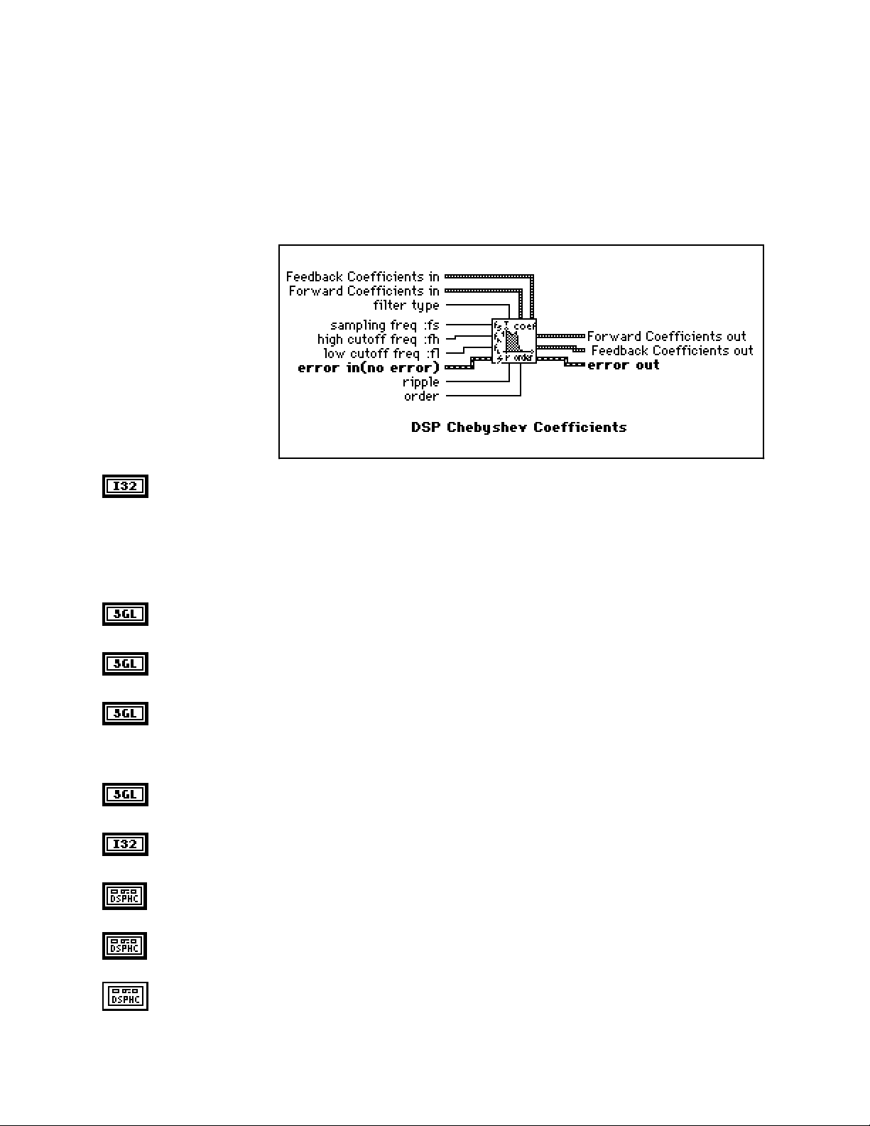
Chapter 2 NI-DSP Analysis VI Reference
Parameter Discussion
The arrays Forward Coefficients in/out and Feedback Coefficients in/out must have a size of at least (order + 1)
for lowpass and highpass filters. The arrays Forward Coefficients in/out and Feedback Coefficients in/out must
have a size of at least (2*order + 1) for bandpass and bandstop filters.
DSP Chebyshev Coefficients
Generates the set of filter
coefficients to implement an
IIR filter as specified by the
Chebyshev filter model.
You can then pass
coefficients to the DSP IIR
Filter VI to filter a sequence
of data.
filter type specifies the passband of the filter. It has four options:
0: lowpass.
1: highpass.
2: bandpass.
3: bandstop.
filter type defaults to lowpass.
sampling freq : fs is the sampling frequency and must be greater than 0. If it is less than or equal to
zero, the VI returns an error. sampling Freq : fs defaults to 1.0.
high cutoff freq: fh is the high cutoff frequency. The VI ignores this parameter when filter type is
lowpass. high cutoff freq: fh defaults to 0.45.
low cutoff freq: fl is the low cutoff frequency. The VI ignores this parameter when filter type is
highpass. low cutoff freq: fl defaults to 0.125.
Note: fh and fl must observe the Nyquist criterion: 0 ≤ fl ≤ fh ≤ fs /2.
ripple must be greater than 0. If ripple is less than or equal to zero, the VI returns an error. ripple
defaults to 0.1.
order must be greater than zero. If order is less than or equal to zero, the VI returns an error. order
defaults to 2.
Forward Coefficients in is a DSP Handle Cluster that indicates the memory buffer on the DSP board
that will contain the forward coefficients.
Feedback Coefficients in is a DSP Handle Cluster that indicates the memory buffer on the DSP board
that will contain the feedback coefficients.
Forward Coefficients out is a DSP Handle Cluster that is identical to the Forward Coefficients in, but
with the forward coefficients already stored in the memory buffer on the DSP board.
NI-DSP SRM for LabVIEW for Windows 2-10 Part 3: NI-DSP Function Reference
Page 46
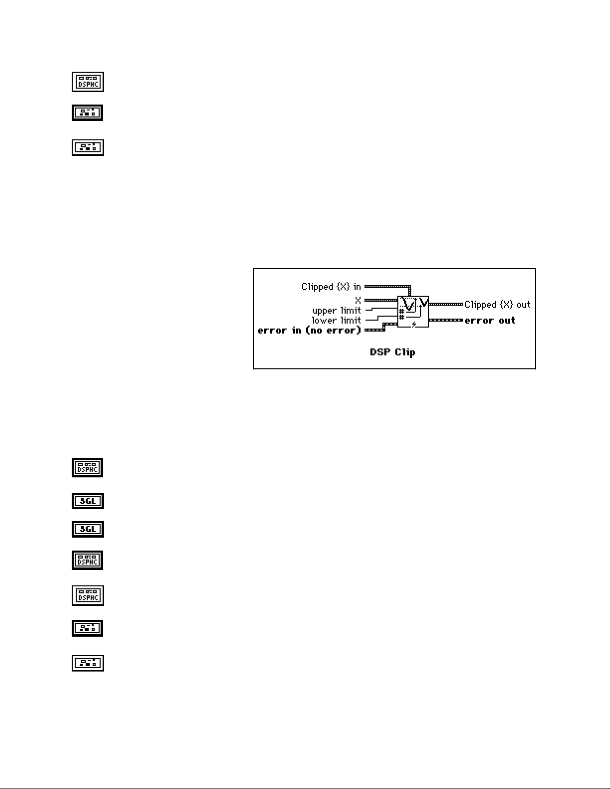
Chapter 2 NI-DSP Analysis VI Reference
Feedback Coefficients out is a DSP Handle Cluster that is identical to the Feedback Coefficients in,
but with the feedback coefficients already stored in the memory buffer on the DSP board.
error in (no error) contains the error information from a previous VI. If an error occurs, it is passed out
error out and no other calls are made.
error out contains the error information for this call.
Parameter Discussion
The arrays Forward Coefficients in/out and Feedback Coefficients in/out have to have a size of at least (order +
1) for lowpass and highpass filters.The arrays Forward Coefficients in/out and Feedback Coefficients in/out have
to have a size of at least (2*order + 1) for bandpass and bandstop filters.
DSP Clip
Clips the input array values. The range of
the resulting output array is [lower:upper].
Let Y represent the output array. The i
element of the resulting array is obtained by
using the following formulas:
th
upper if X(i) > upper
lower if X(i) < lower
Y(i) =
for i = 0, 1, 2, …, size-1 ,
where n is the number of elements in X.
The operation can be performed in place; that is, the input and output arrays can be the same DSP Handle Cluster.
X(i) otherwise
X is a DSP Handle Cluster that indicates the memory buffer on the DSP board that contains the input
signal array X.
upper limit. upper limit ≥ lower limit. upper limit defaults to 1.0.
lower limit. lower limit defaults to 0.0.
Clipped{X} in is a DSP Handle Cluster that indicates the memory buffer on the DSP board that will
contain the output array of Clipped{X}.
Clipped{X} out is a DSP Handle Cluster that is identical to Clipped {X} in, but with the Clipped{X}
already stored in the memory buffer on the DSP board.
error in (no error) contains the error information from a previous VI. If an error occurs, it is passed out
error out and no other calls are made.
error out contains the error information for this call.
NI-DSP SRM for LabVIEW for Windows 2-11 Part 3: NI-DSP Function Reference
Page 47

NI-DSP Analysis VI Reference Chapter 2
DSP Complex FFT
Computes the Fast Fourier transform of
the complex input sequence X. If Y
represents the complex output sequence,
then:
Y = F{X}.
Re{X} is a DSP Handle Cluster that indicates the memory buffer on the DSP board that contains the real
part of the input signal array X.
Im{X} is a DSP Handle Cluster that indicates the memory buffer on the DSP board that contains the
imaginary part of input signal array X.
Notes: The number of elements for the input array must be a power of 2.
If the size of Re{X} is different from the size of Im{X}, the VI uses the smaller number as the
size of the Complex FFT.
The operation is performed in place and the input array Re{X} and Im{X} is overwritten by the
Re FFT{X} and Im FFT{X}.
The largest complex FFT that can be computed depends upon the amount of memory on your
board.
Re FFT{X} is a DSP Handle Cluster that is identical to Re{X}, but with the real part of FFT{X}already
stored in the memory buffer on the DSP board.
Im FFT{X} is a DSP Handle Cluster that is identical to Im{X}, but with the imaginary part of
FFT{X}already stored in the memory buffer on the DSP board.
error in (no error) contains the error information from a previous VI. If an error occurs, it is passed out
error out and no other calls are made.
error out contains the error information for this call.
Part 3: NI-DSP Function Reference 2-12 NI-DSP SRM for LabVIEW for Windows
Page 48

Chapter 2 NI-DSP Analysis VI Reference
DSP Convolution
Computes the convolution of the input
sequences X and Y. The convolution Cxy(t), of
the signals x(t) and y(t), is defined as follows:
∞
Cxy(t) = x(t)
where the symbol * denotes convolution.
For the discrete implementation of the convolution, let Cxy represent the output sequence X * Y, n be the number of
elements in the input sequence X, and m be the number of elements in the input sequence Y. Assuming that indexed
elements of X and Y that lie outside their range are zero,
xi = 0, i < 0 or i ≥ n
and
y
= 0, j < 0 or j ≥ m,
j
then you obtain the elements of Cxy using:
n-1
Cxyi =
k = 0
∑
xk y
y(t) = ∫
*
i-k
x(τ) y(t-τ) dτ ,
-∞
for i = 0, 1, 2, …, size-1 ,
size = n + m - 1,
where size is the total number of elements in the output sequence X * Y.
X is a DSP Handle Cluster that indicates the memory buffer on the DSP board that contains the input
signal array X.
Y is a DSP Handle Cluster that indicates the memory buffer on the DSP board that contains the input
signal array Y.
Cxy in is a DSP Handle Cluster that indicates the memory buffer on the DSP board that will contain the
convolution of X with Y.
Note: The size of Cxy in must be (n+m-1) elements long. n is the size of X, m is the size of Y. You
cannot perform the operation in place.
Cxy out is a DSP Handle Cluster that is identical to the Cxy in but with the convolution of X and Y
already stored in the memory buffer on the DSP board.
error in (no error) contains the error information from a previous VI. If an error occurs, it is passed out
error out and no other calls are made.
error out contains the error information for this call.
NI-DSP SRM for LabVIEW for Windows 2-13 Part 3: NI-DSP Function Reference
Page 49

NI-DSP Analysis VI Reference Chapter 2
DSP Correlation
Computes the cross correlation of the input
sequences X and Y. The cross correlation Rxy(t)
of the signals x(t) and y(t) is defined as follows:
∞
Rxy(t) = x(t) ⊗ y(t) =
where the symbol ⊗ denotes correlation.
x(t) y(t+t) dt ,
∫
-∞
For the discrete implementation of the correlation, let R
elements in the input sequence X, and m be the number of elements in the input sequence Y. You then obtain the
elements of R
R
xy i
using the following formula:
xy
n-1
=
x[k] y[k+m-1] for i = 0, 1, 2, …, m+n-1 ,
∑
k=0
X is a DSP Handle Cluster that indicates the memory buffer on the DSP board that contains the input
signal array X.
Y is a DSP Handle Cluster that indicates the memory buffer on the DSP board that contains the input
signal array Y.
Rxy in is a DSP Handle Cluster that indicates the memory buffer on the DSP board that will contain the
correlation results.
Note: The size of Rxy in must be at least (n+m-1) elements long. n is the size of X, m is the size
of Y.
Rxy out is a DSP Handle Cluster that is identical to the Rxy in, but with the correlation of X and Y
already stored in the memory buffer on the DSP board.
Note: If X and Y are the same array, an auto correlation is performed, otherwise, a cross correlation is
performed. You cannot perform the operation in place.
error in (no error) contains the error information from a previous VI. If an error occurs, it is passed out
error out and no other calls are made.
represent the output sequence X ⊗ Y, n be the number of
xy
error out contains the error information for this call.
Part 3: NI-DSP Function Reference 2-14 NI-DSP SRM for LabVIEW for Windows
Page 50

Chapter 2 NI-DSP Analysis VI Reference
DSP Cross Power
Computes the cross power spectrum of the input
sequences X and Y. The cross power, Sxy(f), of
the signals x(t) and y(t) is defined as follows:
Sxy(f) = X*(f)Y(f)
where X*(f) is the complex conjugate of X(f),
X(f) = F{x(t)}, and
Y(f) = F{y(t)}.
This VI uses the FFT routine to compute the cross power spectrum, that is given by the following formula:
S
n = 2
where Sxy represents the complex output sequence Sxy, and
1
=
xy
F*{X} F{Y} ,
2
n
k
n is the number of samples that can accommodate both input sequences X and Y.
X is a DSP Handle Cluster that indicates the memory buffer on the DSP board that contains the input
signal array X.
Y is a DSP Handle Cluster that indicates the memory buffer on the DSP board that contains the input
signal array Y.
Notes: If the size of X is different than Y, the VI uses the smaller number as the size of input arrays X
Re{Sxy} is a DSP Handle Cluster that is identical to X, but with the real part of Sxy already stored in the
memory buffer on the DSP board.
for k = 1, 2, 3, …, 23,
and Y. The number of elements for the input arrays must be a power of two.
The operation is performed in place and the input arrays X and Y are overwritten by the
outputs Re{Sxy} and Im{Sxy}.
The largest Cross Power Spectrum that can be computed depends upon the amount of memory
in your DSP board.
This VI allocates a temporary workspace on the DSP board equal to the size of the input signal
array.
Im{Sxy} is a DSP Handle Cluster that is identical to Y, but with the imaginary part of Sxy already
stored in the memory buffer on the DSP board.
error in (no error) contains the error information from a previous VI. If an error occurs, it is passed out
error out and no other calls are made.
error out contains the error information for this call.
NI-DSP SRM for LabVIEW for Windows 2-15 Part 3: NI-DSP Function Reference
Page 51

NI-DSP Analysis VI Reference Chapter 2
DSP Custom
Use this VI as the interface to
call your own custom functions
written on the DSP board from
LabVIEW. For more details
about how to use this VI, refer
to Part 4, NI-DSP Interface
Utilities, of this manual.
slot is the board ID number. slot defaults to 3.
function code indicates which function on the DSP board LabVIEW is calling. function code defaults
to 0.
Array of Handles in is an array of DSP Handle Clusters that hold all of the references to the input and
output data buffers used in your custom functions on the DSP board.
Array of SGL Scalars in is an array of 32-bit floating-point scalars that hold all of the input 32-bit
floating-point scalars used in your custom functions on the DSP board.
Array of I32 Scalars in is an array of 32-bit long integer scalars that hold all of the input 32-bit long
integer scalars used in your custom functions on the DSP board.
Array of Handles out is an array of DSP Handle Clusters that is identical to Array of Handles in, but
with the output results already stored in the memory buffers on the DSP board.
Array of SGL Scalars out is an array of 32-bit floating-point scalars that is identical to Array of SGL
Scalars in, but with the output results already stored in the array.
Array of I32 Scalars out is an array of 32-bit long integer scalars that is identical to Array of I32
Scalars in, but with the output results already stored in the array.
error in (no error) contains the error information from a previous VI. If an error occurs, it is passed out
error out and no other calls are made.
error out contains the error information for this call.
Part 3: NI-DSP Function Reference 2-16 NI-DSP SRM for LabVIEW for Windows
Page 52

Chapter 2 NI-DSP Analysis VI Reference
DSP Decimate
Decimates the input sequence X by the
decimating factor and the averaging control.
If Y represents the output sequence Decimated
Array, the elements of the sequence Y are
obtained using:
X
im
Y
i
m−1
=
1
for i = 0, 1, 2, …, size -1
m
∑
k=0
X
i(m+ k)
if ave = no averaging
if ave = averaging
size = trunc
where n is the number of elements in X,
m is the decimating factor,
ave is the averaging option, and
size is the number of elements in the output sequence Y.
n
,
()
m
X is a DSP Handle Cluster that indicates the memory buffer on the DSP board that contains the input
signal array.
Y in is a DSP Handle Cluster that indicates the memory buffer on the DSP board that will contain the
decimated output array.
Y out is a DSP Handle Cluster that is identical to Y in, but with the results of the decimated array
already stored in the memory buffer on the DSP board.
decimating factor must be greater than zero:
0 < decimating factor ≤ n.
If decimating factor is greater than the number of samples in X or less than or equal to zero, the VI
returns an error. decimating factor defaults to 1.
averaging has two options:
0: averaging.
1: no averaging.
averaging defaults to no averaging.
error in (no error) contains the error information from a previous VI. If an error occurs, it is passed out
error out and no other calls are made.
error out contains the error information for this call.
The operation can be performed in place; that is, the input X and the output Y can be the same DSP Handle Cluster.
NI-DSP SRM for LabVIEW for Windows 2-17 Part 3: NI-DSP Function Reference
Page 53

NI-DSP Analysis VI Reference Chapter 2
DSP Deconvolution
Computes the deconvolution of the input
sequences X and Y. The convolution operation
can be realized using Fourier identities because
x(t)
y(t) ⇔ X(f) Y(f)
*
is a Fourier transform pair, where the symbol
denotes convolution, and the deconvolution is
the inverse of the convolution operation. If h(t) is the signal resulting from the deconvolution of the signals x(t) and
y(t), the VI obtains h(t) using the equation
X(f)
h(t) = F
where X(f) is the Fourier transform of x(t), and
The VI performs the discrete implementation of the deconvolution using the following steps.
1. Compute the Fourier transform of the input sequence X * Y.
2. Compute the Fourier transform of the input sequence Y.
3. Divide the Fourier transform of X * Y by the Fourier transform of Y. Call the new sequence H.
4. Compute the inverse Fourier transform of H to obtain the deconvoluted sequence X.
-1
{}
Y(f) is the Fourier transform of y(t).
Cxy is a DSP Handle Cluster that indicates the memory buffer on the DSP board that contains the input
signal array Cxy. The number of elements in Cxy must be greater than or equal to the number of
elements in Y.
Y is a DSP Handle Cluster that indicates the memory buffer on the DSP board that contains the input
signal array Y.
Y(f)
,
*
X in is a DSP Handle Cluster that indicates the memory buffer on the DSP board that will contain the
deconvolution results.
Note: The size of X in must be n elements long, although only (n-m+1) elements are valid. n is the
size of Cxy, m is the size of Y.
X out is a DSP Handle Cluster that is identical to X in, but with the deconvolution results already stored
in the memory buffer on the DSP board.
error in (no error) contains the error information from a previous VI. If an error occurs, it is passed out
error out and no other calls are made.
error out contains the error information for this call.
Note: The deconvolution operation is a numerically unstable operation, and it is not always possible to solve the
system numerically. Computing the deconvolution via FFTs is perhaps the most stable generic algorithm
that does not require sophisticated DSP techniques. However, it is not free of errors (for example, when
there are zeros in the Fourier transform of the input sequence Y).
Part 3: NI-DSP Function Reference 2-18 NI-DSP SRM for LabVIEW for Windows
Page 54

Chapter 2 NI-DSP Analysis VI Reference
DSP Derivative
Performs a discrete differentiation of the
sampled signal X. The differentiation f(t) of a
function F(t) is defined as follows:
d
f(t) =
Let Y represent the sampled output sequence
d/dt X. The discrete implementation is given
by the following formula:
yi =
where n is the number of samples in x(t)
initial condition and final condition minimize the error at the boundaries.
F(t).
dt
1
(x
- x
) for i = 0, 1, 2, …, n-1.
i+1
2dt
i-1
x-1 is specified by initial condition when i = 0, and
xn is specified by final condition when i = n-1.
X is a DSP Handle Cluster that indicates the memory buffer on the DSP board that contains the input
signal array.
initial condition defaults to 0.0.
final condition defaults to 0.0.
dt is the sampling interval and must be greater than zero. If dt is less than or equal to zero, the VI
returns an error. dt defaults to 1.0.
Y in is a DSP Handle Cluster that indicates the memory buffer on the DSP board that will contain the
results of the differentiation of X.
Y out is a DSP Handle Cluster that is identical to Y in, but with the results of differentiation already
stored in the memory buffer on the DSP board.
error in (no error) contains the error information from a previous VI. If an error occurs, it is passed out
error out and no other calls are made.
error out contains the error information for this call.
The operation can be performed in place; that is, the input X and the output Y can be the same DSP Handle Cluster.
NI-DSP SRM for LabVIEW for Windows 2-19 Part 3: NI-DSP Function Reference
Page 55

NI-DSP Analysis VI Reference Chapter 2
DSP Divide
Divide array X by array Y. The ith element of
the output array Z is obtained using the
following formula:
Z(i) = X(i) / Y(i).
for i = 0, 1, 2, …, n-1.
where n is the smaller number of elements in
X and Y.
X is a DSP Handle Cluster that indicates the memory buffer on the DSP board that contains the input
signal array X.
Y is a DSP Handle Cluster that indicates the memory buffer on the DSP board that contains the input
signal array Y.
Z in is a DSP Handle Cluster that indicates the memory buffer on the DSP board that will contain the
results of X(i) / Y(i).
Z out is a DSP Handle Cluster that is identical to Z in, but with the divided results already stored in the
memory buffer on the DSP board.
error in (no error) contains the error information from a previous VI. If an error occurs, it is passed out
error out and no other calls are made.
error out contains the error information for this call.
The operation can be performed in place; that is, the input and the output arrays can be the same DSP Handle
Cluster.
Part 3: NI-DSP Function Reference 2-20 NI-DSP SRM for LabVIEW for Windows
Page 56

Chapter 2 NI-DSP Analysis VI Reference
DSP Elliptic Coefficients
Generates the set of filter
coefficients to implement a
digital elliptic IIR filter. You
can then pass these
coefficients to the DSP IIR
Filter VI.
filter type specifies the passband of the filter. filter type has four options:
0: lowpass.
1: highpass.
2: bandpass.
3: bandstop.
filter type defaults to lowpass.
sampling freq : fs is the sampling frequency and must be greater than 0. If it is less than or equal to
zero, the VI returns an error. sampling freq : fs defaults to 1.0.
high cutoff freq: fh is the high cutoff frequency. The VI ignores this parameter when filter type is
lowpass. high cutoff freq: fh defaults to 0.45.
low cutoff freq: fl is the low cutoff frequency. The VI ignores this parameter when filter type is
highpass. high cutoff freq: fh defaults to 0.125.
Note: fh and fl must observe the Nyquist criterion: 0 ≤ fl ≤ fh ≤ fs /2.
passband ripple must be greater than 0, and you must express it in decibels. If passband ripple is less
than or equal to zero, the VI returns an error. passband ripple defaults to 1.0.
order must be greater than zero. If order is less than or equal to zero, the VI returns an error. order
defaults to 2.
stopband attenuation must be greater than 0, and you must express it in decibels. If stopband
attenuation is less than or equal to zero, the VI returns an error. stopband attenuation defaults to 60.0.
Forward Coefficients in is a DSP Handle Cluster that indicates the memory buffer on the DSP board
that will contain the forward coefficients.
Feedback Coefficients in is a DSP Handle Cluster that indicates the memory buffer on the DSP board
that will contain the feedback coefficients.
Forward Coefficients out is a DSP Handle Cluster that is identical to Forward Coefficients in, but
with the forward coefficients already stored in the memory buffer on the DSP board.
Feedback Coefficients out is a DSP Handle Cluster that is identical to Feedback Coefficients in, but
with the feedback coefficients already stored in the memory buffer on the DSP board.
NI-DSP SRM for LabVIEW for Windows 2-21 Part 3: NI-DSP Function Reference
Page 57

NI-DSP Analysis VI Reference Chapter 2
error in (no error) contains the error information from a previous VI. If an error occurs, it is passed out
error out and no other calls are made.
error out contains the error information for this call.
Parameter Discussion
The arrays Forward Coefficients in/out and Feedback Coefficients in/out must have a size of at least (order + 1)
for lowpass and highpass filters. The arrays Forward Coefficients in/out and Feedback Coefficients in/out must
have a size of at least (2*order + 1) for bandpass and bandstop filters.
Part 3: NI-DSP Function Reference 2-22 NI-DSP SRM for LabVIEW for Windows
Page 58
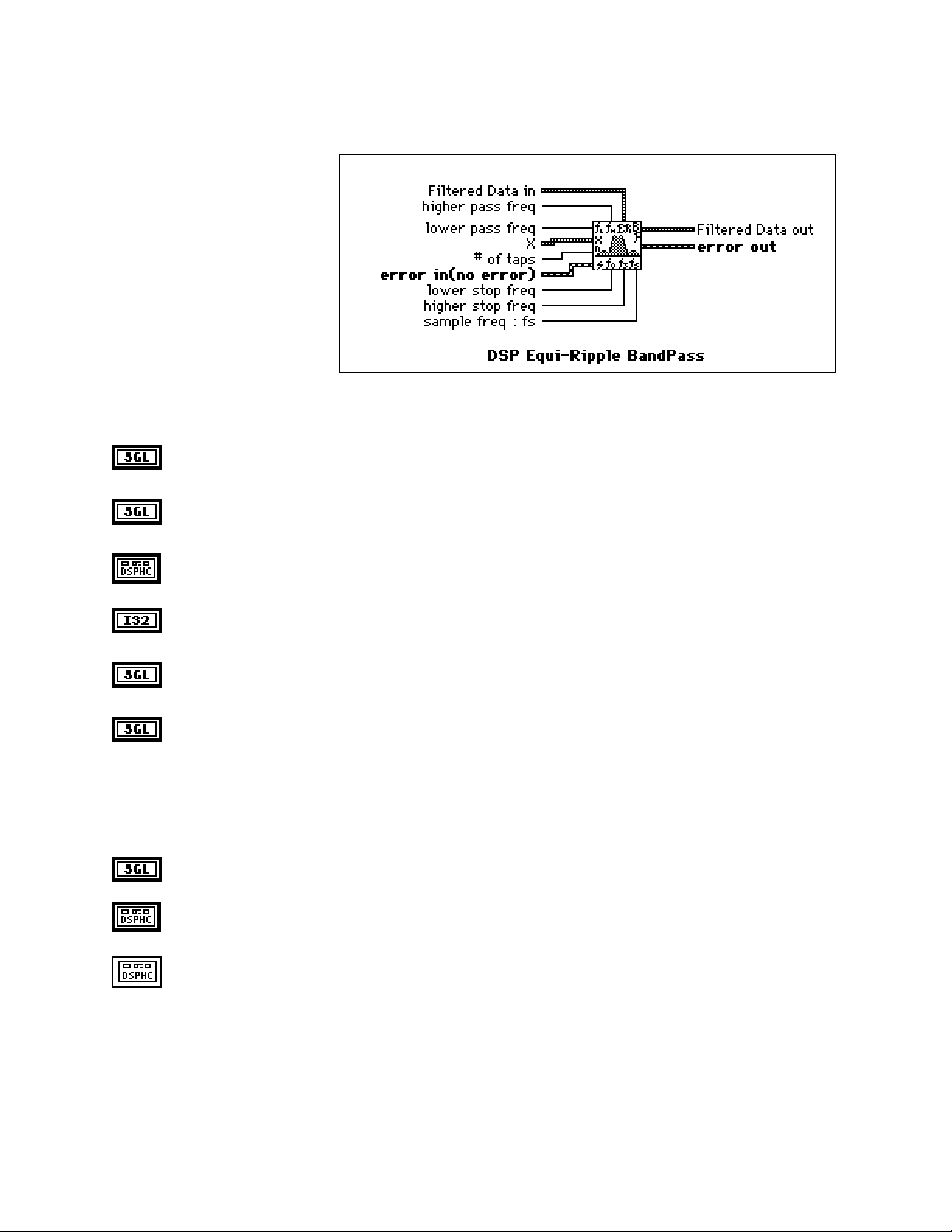
Chapter 2 NI-DSP Analysis VI Reference
DSP Equi-Ripple BandPass
Generates a bandpass FIR filter
with equi-ripple characteristics
using the Parks-McClellan
algorithm and the number of taps,
lower stop frequency, higher stop
frequency, lower pass frequency,
higher pass frequency, and
sampling frequency. The VI then
filters the input sequence X to
obtain the bandpass filtered linearphase sequence Filtered Data.
The first stopband of the filter
region goes from zero (DC) to the
lower stop frequency. The passband region goes from the lower pass frequency to the higher pass frequency, and
the second stopband region goes from the higher stop frequency to the Nyquist frequency.
higher pass freq must be greater than lower pass freq frequency. If higher pass freq is less than or
equal to lower pass freq, the VI returns an error. higher pass freq defaults to 0.3.
lower pass freq must be greater than the lower stop freq. If lower pass freq is less than or equal to
lower stop freq, the VI returns an error. lower pass freq defaults to 0.2.
X is a DSP Handle Cluster that indicates the memory buffer on the DSP board that contains the input
data array.
# of taps must be greater than 0. If the number of taps is less than or equal to zero, the VI returns an
error. # of taps defaults to 32.
lower stop freq must be greater than zero. If lower stop freq is less than or equal to zero, the VI
returns an error. lower stop freq defaults to 0.1.
higher stop freq must be greater than higher pass freq and must observe the Nyquist criterion:
0 < f0 < f1 < f2 < f3 ≤ 0.5fs ,
where f0 is lower stop freq, f1 is lower pass freq, f2 is higher pass freq, f3 is the higher stop freq, and
fs is the sampling frequency. If any of these conditions is violated, the VI returns an error. higher stop
freq defaults to 0.4.
sampling freq: fs defaults to 1.0.
Filtered Data in is a DSP Handle Cluster that indicates the memory buffer on the DSP board that will
contain the filtered data output.
Filtered Data out is a DSP Handle Cluster that is identical to Filtered Data in, but with the filtered
data already stored in the memory buffer on the DSP board. Because the VI filters via convolution, the
number of elements, k, in Filtered Data is as follows:
k = n + m - 1,
where n is the number of elements in X, and m is the number of taps.
NI-DSP SRM for LabVIEW for Windows 2-23 Part 3: NI-DSP Function Reference
Page 59

NI-DSP Analysis VI Reference Chapter 2
A delay is also associated with the output sequence
delay =
error in (no error) contains the error information from a previous VI. If an error occurs, it is passed out
error out and no other calls are made.
error out contains the error information for this call.
The operation cannot be performed in place; that is, the input X and the output Filtered Data cannot be the same
DSP Handle Cluster.
m-1
2
.
Part 3: NI-DSP Function Reference 2-24 NI-DSP SRM for LabVIEW for Windows
Page 60
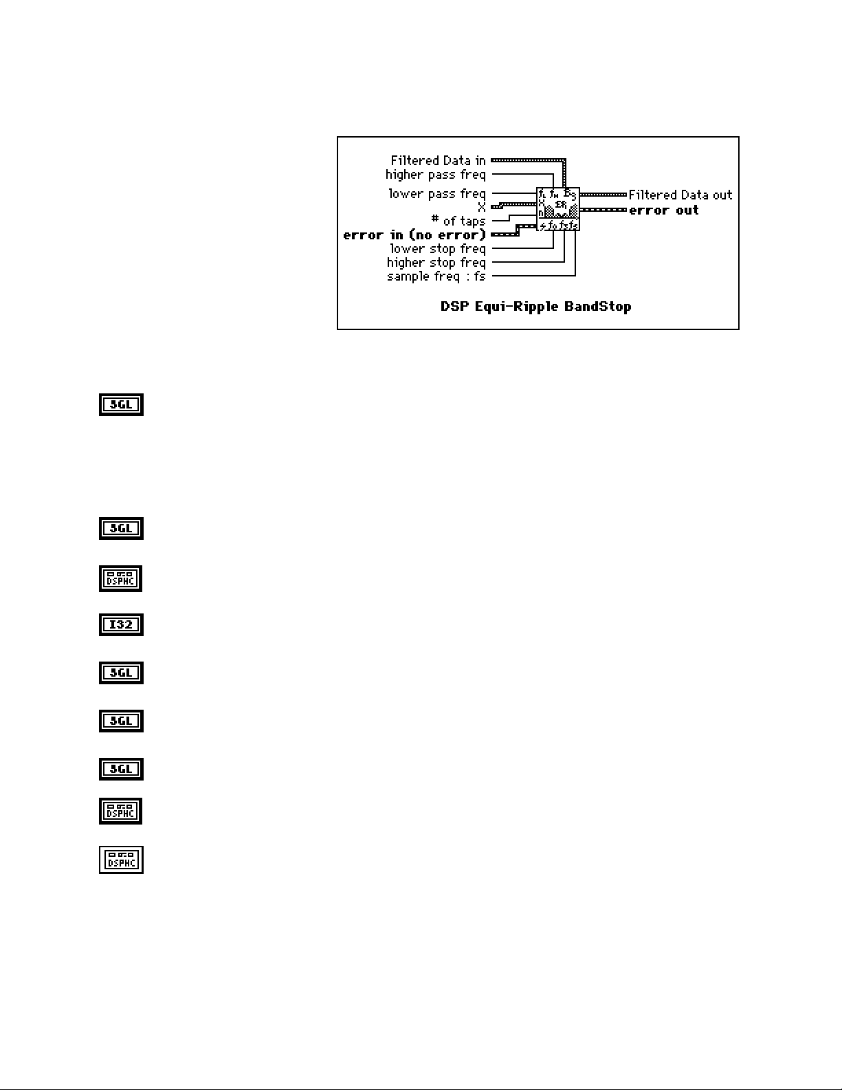
Chapter 2 NI-DSP Analysis VI Reference
DSP Equi-Ripple BandStop
Generates a bandstop FIR digital filter
with equi-ripple characteristics using the
Parks-McClellan algorithm and number
of taps, lower pass frequency, higher
pass frequency, lower stop frequency,
higher stop frequency, and sampling
frequency. The VI then filters the input
sequence X to obtain the bandstop
filtered linear-phase sequence Filtered
Data.
The first passband region of the filter
goes from zero (DC) to the lower pass
frequency. The stopband region goes
from the lower stop frequency to the higher stop frequency, and the second passband region goes from the higher
pass frequency to the Nyquist frequency.
higher pass freq must be greater than higher stop freq and observe the Nyquist criterion:
0 < f0 < f1 < f2 < f3 ≤ 0.5fs,
where f0 is the lower pass freq, f1 is the lower stop freq, f2 is the higher stop freq, f3 is the higher pass
freq, and fs is the sampling freq. If any of these conditions is violated, the VI returns an error. higher
pass freq defaults to 0.4.
lower pass freq must be greater than zero. If lower pass freq is less than or equal to 0, the VI returns
an error. lower pass freq defaults to 0.1.
X is a DSP Handle Cluster that indicates the memory buffer on the DSP board that contains the input
data array.
# of taps must be odd and must be greater than 0. If the number of taps is an even number or is less
than or equal to zero, the VI returns an error. # of taps defaults to 31.
lower stop freq must be greater than lower pass freq. If lower stop freq is less than or equal to lower
pass freq, the VI returns an error. lower stop freq defaults to 0.2.
higher stop freq must be greater than lower stop freq. If higher stop freq is less than or equal to
lower stop freq, the VI returns an error. higher stop freq defaults to 0.3.
sampling freq: fs defaults to 1.0.
Filtered Data in is a DSP Handle Cluster that indicates the memory buffer on the DSP board that will
contain the filtered data output.
Filtered Data out is a DSP Handle Cluster that is identical to Filtered Data in, but with the filtered
data already stored in the memory buffer on the DSP board. Because the VI filters via convolution, the
number of elements, k, in Filtered Data is as follows:
k = n + m - 1,
where n is the number of elements in X, and m is the number of taps.
NI-DSP SRM for LabVIEW for Windows 2-25 Part 3: NI-DSP Function Reference
Page 61

NI-DSP Analysis VI Reference Chapter 2
A delay is also associated with the output sequence:
delay =
error in (no error) contains the error information from a previous VI. If an error occurs, it is passed out
error out and no other calls are made.
error out contains the error information for this call.
The operation cannot be performed in place; that is, the input X and the output Filtered Data cannot be the same
DSP Handle Cluster.
m-1
2
.
Part 3: NI-DSP Function Reference 2-26 NI-DSP SRM for LabVIEW for Windows
Page 62

Chapter 2 NI-DSP Analysis VI Reference
DSP Equi-Ripple HighPass
Generates a highpass FIR filter with
equi-ripple characteristics using the
Parks-McClellan algorithm and the
number of taps, high frequency, stop
frequency, and sampling frequency. The
VI then filters the input sequence X to
obtain the highpass filtered linear-phase
sequence Filtered Data.
The stopband of the filter goes from zero
(DC) to the stop frequency. The
transition band goes from the stop
frequency to the high frequency, and
the passband goes from the high frequency to the Nyquist frequency.
X is a DSP Handle Cluster that indicates the memory buffer on the DSP board that contains the input
data array.
# of taps must be greater than 0 and must be an odd number. If the number of taps is an even number or
is less than or equal to zero, the VI returns an error. # of taps defaults to 31.
stop freq must be greater than zero. If stop freq is less than or equal to 0, the VI returns an error. stop
freq defaults to 0.2.
high freq must be greater than stop freq and observe the Nyquist criterion:
0 < f0 < f1 ≤ 0.5fs,
where f0 is the stop freq, f1 is the high freq, and fs is the sampling frequency. If any of these conditions
is violated, the VI returns an error. high freq defaults to 0.3.
sampling freq: fs defaults to 1.0.
Filtered Data in is a DSP Handle Cluster that indicates the memory buffer on the DSP board that will
contain the filtered data output.
Filtered Data out is a DSP Handle Cluster that is identical to Filtered Data in, but with the filtered
data already stored in the memory buffer on the DSP board. Because the VI filters via convolution, the
number of elements, k, in Filtered Data is:
k = n + m - 1,
where n is the number of elements in X, and m is the number of taps.
A delay is also associated with the output sequence:
delay =
m-1
2
.
NI-DSP SRM for LabVIEW for Windows 2-27 Part 3: NI-DSP Function Reference
Page 63

NI-DSP Analysis VI Reference Chapter 2
error in (no error) contains the error information from a previous VI. If an error occurs, it is passed out
error out and no other calls are made.
error out contains the error information for this call.
The operation cannot be performed in place; that is, the input X and the output Filtered Data out cannot be the
same DSP Handle Cluster.
Part 3: NI-DSP Function Reference 2-28 NI-DSP SRM for LabVIEW for Windows
Page 64

Chapter 2 NI-DSP Analysis VI Reference
DSP Equi-Ripple LowPass
Generates a lowpass FIR filter with equiripple characteristics using the ParksMcClellan algorithm and the number of
taps, pass frequency, stop frequency, and
sampling frequency. The VI then filters
the input sequence X to obtain the
lowpass filtered linear-phase sequence
Filtered Data.
The passband of the filter goes from zero
(DC) to pass freq. The transition band
goes from pass freq to stop freq, and
the stopband goes from stop freq to the
Nyquist frequency.
X is a DSP Handle Cluster that indicates the memory buffer on the DSP board that contains the input
data array.
# of Taps must be greater than 0. If the number of taps is less than or equal to zero, the VI returns an
error. # of Taps defaults to 31.
pass freq must be greater than 0. If pass freq is less than or equal to zero, the VI returns an error. pass
freq defaults to 0.2.
stop freq must be greater than the pass freq and observe the Nyquist criterion:
0 < f0 < f1 ≤ 0.5fs,
where f0 is the pass freq, f1 is the stop freq, and fs is the sampling frequency. If any of these conditions
is violated, the VI returns an error. stop freq defaults to 0.3.
sampling freq: fs defaults to 1.0.
Filtered Data in is a DSP Handle Cluster that indicates the memory buffer on the DSP board that will
contain the filtered data output.
Filtered Data out is a DSP Handle Cluster that is identical to Filtered Data in, but with the filtered
data already stored in the memory buffer on the DSP board. Because the VI filters via convolution, the
number of elements, k, in Filtered Data out is:
k = n + m - 1,
where n is the number of elements in X, and
m is the number of taps.
A delay equal to
m-1
is also associated with the output sequence.
2
error in (no error) contains the error information from a previous VI. If an error occurs, it is passed out
error out and no other calls are made.
error out contains the error information for this call.
The operation cannot be performed in place; that is, the input X and the output Filtered Data cannot be the same
DSP Handle Cluster.
NI-DSP SRM for LabVIEW for Windows 2-29 Part 3: NI-DSP Function Reference
Page 65

NI-DSP Analysis VI Reference Chapter 2
DSP Exact Blackman Window
Applies an Exact Blackman window to
the input sequence X. If Y represents
the output sequence Exact
Blackman{X}, the elements of Y are
obtained using the formula:
yi = xi [0.42659071
- 0.49656062 cos(w)
+ 0.07684867 cos(2w)]
for i = 0, 1, 2, … , n-1
2πi
w =
where n is the number of elements in X.
,
n
X is a DSP Handle Cluster that indicates the memory buffer on the DSP board that contains the input
signal array.
Note: The operation is performed in place and the input array X is overwritten by the output Exact
Blackman {X}.
Exact Blackman {X} is a DSP Handle Cluster that is identical to X, but with the results of Exact
Blackman {X} already stored in the memory buffer on the DSP board.
error in (no error) contains the error information from a previous VI. If an error occurs, it is passed out
error out and no other calls are made.
error out contains the error information for this call.
Part 3: NI-DSP Function Reference 2-30 NI-DSP SRM for LabVIEW for Windows
Page 66

Chapter 2 NI-DSP Analysis VI Reference
DSP Exponential Window
Applies an exponential window to the input
sequence X. If Y represents the output
sequence Exponential{X}, the elements of
Y are obtained using the formula:
yi = xi exp(a * i)
for i = 0, 1, 2, … , n-1,
ln |f|
a =
where f is the final value, and
You can use the Exponential Window VI to analyze transients.
,
n - 1
n is the number of elements in X.
X is a DSP Handle Cluster that indicates the memory buffer on the DSP board that contains the input
signal array.
Note: The operation is performed in place and the input array X is overwritten by the output
Exponential {X}.
final value defaults to 0.10.
Exponential {X} is a DSP Handle Cluster that is identical to X, but with the results of Exponential {X}
already stored in the memory buffer on the DSP board.
error in (no error) contains the error information from a previous VI. If an error occurs, it is passed out
error out and no other calls are made.
error out contains the error information for this call.
NI-DSP SRM for LabVIEW for Windows 2-31 Part 3: NI-DSP Function Reference
Page 67

NI-DSP Analysis VI Reference Chapter 2
DSP FHT
Computes the fast Hartley transform (FHT) of
the input sequence X. The Hartley transform
of a function x(t) is defined as follows:
∞
X(f) = ∫
where cas(x) = cos(x) + sin(x).
If Y represents the output sequence FHT {X} obtained via the FHT, then Y is obtained through the discrete
implementation of the Hartley integral:
Yk =
where n is the number of elements in X.
x(t) cas(2πft) dt
-∞
n-1
Xi cas
∑
i=0
X is a DSP Handle Cluster that indicates the memory buffer on the DSP board that contains the input
signal array.
2π ik
, for k = 0, 1, 2, … , n-1 .
()
n
Notes: The number of elements for the input array must be a power of two.
The operation is performed in place and the input array X is overwritten by the output
FHT{X}.
The largest FHT that can be computed depends upon the amount of memory on your DSP
board.
FHT{X} is a DSP Handle Cluster that is identical to X, but with the results of FHT{X} already stored in
the memory buffer on the DSP board.
error in (no error) contains the error information from a previous VI. If an error occurs, it is passed out
error out and no other calls are made.
error out contains the error information for this call.
The Hartley transform maps real-valued sequences into real-valued frequency domain sequences. You can use it
instead of the Fourier transform to convolve signals, deconvolve signals, correlate signals, and find the power
spectrum. Furthermore, you can derive the Fourier transform from the Hartley transform.
When the sequences to be processed are real-valued sequences, the Fourier transform produces complex-valued
sequences in which half of the information is redundant. The advantage of using the Hartley transform instead of
the Fourier transform is that the Hartley transform uses half the memory to produce the same information the FFT
produces. Further, the FHT is calculated in place and is as efficient as the Fourier transform.
Part 3: NI-DSP Function Reference 2-32 NI-DSP SRM for LabVIEW for Windows
Page 68

Chapter 2 NI-DSP Analysis VI Reference
DSP Flat Top Window
Applies a flat top window to the input sequence
X. If Y represents the output sequence
Flattop{X}, the elements of Y are obtained
using the formula:
yi = xi [0.2810639 - 0.5208972 cos(w)
+ 0.1980399 cos(2w)]
for i = 0, 1, 2, … , n-1
2πi
w =
where n is the number of elements in X.
,
n
X is a DSP Handle Cluster that indicates the memory buffer on the DSP board that contains the input
signal array.
Note: The operation is performed in place and the input array X is overwritten by the output
Flattop {X}.
Flattop {X} is a DSP Handle Cluster that is identical to X, but with the results of Flattop {X} already
stored in the memory buffer on the DSP board.
error in (no error) contains the error information from a previous VI. If an error occurs, it is passed out
error out and no other calls are made.
error out contains the error information for this call.
NI-DSP SRM for LabVIEW for Windows 2-33 Part 3: NI-DSP Function Reference
Page 69

NI-DSP Analysis VI Reference Chapter 2
DSP Force Window
Applies a force window to the input sequence X
If Y represents the output sequence Force{X},
the elements of Y are obtained using the
formula:
x
if 0 ≤ i ≤ d
i
yi =
0 elsewhere
for i = 0, 1, 2, …, n-1 ,
d = (0.01)(n)(duty)
where n is the number of elements in X.
You can use the Force Window VI to analyze transients.
X is a DSP Handle Cluster that indicates the memory buffer on the DSP board that contains the input
signal array.
Note: The operation is performed in place and the input array X is overwritten by the output
Force {X}.
duty. 0.0 ≤ duty ≤ 100.0. duty defaults to 50.0.
Force {X} is a DSP Handle Cluster that is identical to X, but with the results of Force {X} already
stored in the memory buffer on the DSP board.
error in (no error) contains the error information from a previous VI. If an error occurs, it is passed out
error out and no other calls are made.
error out contains the error information for this call.
DSP Free Memory
Frees the memory space referred by DSP
Handle Cluster on the specified DSP board.
DSP Handle Cluster is a DSP Handle Cluster that indicates the memory buffer to free.
error in (no error) contains the error information from a previous VI. If an error occurs, it is passed out
error out and the VI also frees the DSP Handle Cluster.
error out contains the error information for this call.
Part 3: NI-DSP Function Reference 2-34 NI-DSP SRM for LabVIEW for Windows
Page 70

Chapter 2 NI-DSP Analysis VI Reference
DSP Gaussian White Noise
Generates a Gaussian distributed
pseudorandom pattern whose
statistical profile is as follows:
(µ, σ) = (0, s) ,
where s is the absolute value of the
specified standard deviation.
standard deviation defaults to 1.0.
seed < 65536.0. If seed > 0.0, the generated noise will be the same in repeated invocations if the seed
value does not change. If seed ≤ 0.0, the VI generates a random value to use as the seed, and the noise
will differ in repeated invocations although the value in seed does not change. seed defaults to 0.0.
Gaussian Pattern in is a DSP Handle Cluster that indicates the memory buffer on the DSP board that
will contain the output Gaussian pattern.
Gaussian Pattern out is a DSP Handle Cluster that is identical to Gaussian Pattern in, but with the
generated pattern already stored in the memory buffer on the DSP board. The largest Gaussian pattern
that can be generated depends upon the amount of memory on your DSP board.
error in (no error) contains the error information from a previous VI. If an error occurs, it is passed out
error out and no other calls are made.
error out contains the error information for this call.
NI-DSP SRM for LabVIEW for Windows 2-35 Part 3: NI-DSP Function Reference
Page 71

NI-DSP Analysis VI Reference Chapter 2
DSP General Cosine Window
Applies a general cosine window to the input
sequence X. If A represents the Cosine
Coefficients input sequence and Y represents
the output sequence GenCos{X}, the elements
of Y are obtained using the formula:
yi = xi
for i = 0, 1, 2, … , n-1
w =
where n is the number of elements in X, and
m-1
(-1)k ak cos (kw)
∑
k=0
2πi
,
n
m is the number of elements in Cosine Coefficients.
X is a DSP Handle Cluster that indicates the memory buffer on the DSP board that contains the input
signal array.
Note: The operation is performed in place and the input array X is overwritten by the output
GenCos {X}.
Cosine Coefficients is a DSP Handle Cluster that indicates the memory buffer on the DSP board that
contains the cosine coefficients.
GenCos {X} is a DSP Handle Cluster that is identical to X, but with the results of GenCos {X} already
stored in the memory buffer on the DSP board.
error in (no error) contains the error information from a previous VI. If an error occurs, it is passed out
error out and no other calls are made.
error out contains the error information for this call.
Part 3: NI-DSP Function Reference 2-36 NI-DSP SRM for LabVIEW for Windows
Page 72

Chapter 2 NI-DSP Analysis VI Reference
DSP Hamming Window
Applies a Hamming window to the input
sequence X. If Y represents the output
sequence Hamming {X}, the elements of Y
are obtained from the formula:
yi = xi [0.54 - 0.46 cos(w)]
for i = 0, 1, 2, …, n-1 ,
2πi
w =
where n is the number of elements in the input sequence X.
,
n
X is a DSP Handle Cluster that indicates the memory buffer on the DSP board that contains the input
data array.
Note: The operation is performed in place and the input array X is overwritten by the output
Hamming {X}.
Hamming {X} is a DSP Handle Cluster that is identical to X, but with the results of Hamming {X}
already stored in the memory buffer on the DSP board.
error in (no error) contains the error information from a previous VI. If an error occurs, it is passed out
error out and no other calls are made.
error out contains the error information for this call.
NI-DSP SRM for LabVIEW for Windows 2-37 Part 3: NI-DSP Function Reference
Page 73

NI-DSP Analysis VI Reference Chapter 2
DSP Handle To Address
Finds the actual DSP address value of
DSP Handle Cluster that indicates a
memory buffer on the DSP board.
You can use the output DSP Address as
the input of the DSP Address terminal in
the DSP DMA Copy(DSP to LV) VI or
the DSP DMA Copy(LV to DSP) VI.
DSP Handle Cluster indicates a memory buffer on the DSP board.
DSP Address is the actual DSP address of the memory buffer on the DSP board referred to by DSP
Handle Cluster.
error in(no error) contains the error information from a previous VI. If an error occurs, it is passed
out error out and no other calls are made.
error out contains the error information for this call.
Part 3: NI-DSP Function Reference 2-38 NI-DSP SRM for LabVIEW for Windows
Page 74

Chapter 2 NI-DSP Analysis VI Reference
DSP Hanning Window
Applies a Hanning window to the input
sequence X. If Y represents the output
sequence Hanning {X}, the elements of Y are
obtained using the formula:
yi = 0.5 xi [1 - cos(w)]
for i = 0, 1, 2, …, n-1 ,
2πi
w =
where n is the number of elements in the input sequence X.
,
n
X is a DSP Handle Cluster that indicates the memory buffer on the DSP board that contains the input
data array.
Note: The operation is performed in place and the input array X is overwritten by the output
Hanning {X}.
Hanning {X} is a DSP Handle Cluster that is identical to X, but with the results of Hanning {X} already
stored in the memory buffer on the DSP board.
error in (no error) contains the error information from a previous VI. If an error occurs, it is passed out
error out and no other calls are made.
error out contains the error information for this call.
NI-DSP SRM for LabVIEW for Windows 2-39 Part 3: NI-DSP Function Reference
Page 75

NI-DSP Analysis VI Reference Chapter 2
DSP IIR Filter
Performs IIR filtering on the
X input array and reports the
result in Y. It uses the arrays
a and b of sizes sza and szb
respectively in implementing
the linear difference equation
that describes IIR filtering:
k = sza - 1 k = szb-1
y[i] = ∑ a(k) * x(i-k) - ∑ b(k) * y(i-k) i = 0,1 ..... ,n-1
k = 0 k = 1
where:
a is the array of forward coefficients describing an IIR filter (obtained from DSP Butterworth Coefficients
VI for example)
b is the array of feedback coefficients describing an IIR filter (obtained from the same filter design VI)
Notes: b(0) = 1.0 in the above equation.
This VI may be called in a loop to perform filtering on data frames that are part of the same data stream.
At time i = 0, the initial conditions on X (for example, X(1-sza) through X(-1)) are obtained from the array
Initial Conditions on input. At exit (the end of the VI execution), this array holds the final conditions on
X that could be used as the initial conditions for the next DSP IIR Filter VI call if you were to call it in a
loop.
At time i = 0, the initial conditions on Y (for example, Y(1-szb) through Y(-1)) are obtained from the array
Initial Conditions on output. At exit (the end of the VI execution), this array holds the final conditions on
Y that could be used as the initial conditions for the next DSP IIR Filter VI call if you were to call it in a
loop.
X is a DSP Handle Cluster that indicates the memory buffer on the DSP board that contains the input
signal array.
Y in is a DSP Handle Cluster that indicates the memory buffer on the DSP board that will contain the
output array of filtered data.
Initial Conditions on input is a DSP Handle Cluster that indicates the memory buffer on the DSP board
that contains the initial conditions on input at time zero.
Initial Conditions on output is a DSP Handle Cluster that indicates the memory buffer on the DSP
board that contains the initial conditions on output at time zero.
Forward Coefficients is a DSP Handle Cluster that indicates the memory buffer on the DSP board that
contains the forward coefficients of the IIR filter.
Feedback Coefficients is a DSP Handle Cluster that indicates the memory buffer on the DSP board that
contains the feedback coefficients of the IIR filter.
Part 3: NI-DSP Function Reference 2-40 NI-DSP SRM for LabVIEW for Windows
Page 76
Chapter 2 NI-DSP Analysis VI Reference
Y out is a DSP Handle Cluster that is identical to Y in, but with the filtered data already stored in the
memory buffer on the DSP board.
Final Conditions on input is a DSP Handle Cluster that is identical to Initial Conditions on input, but
contains the final conditions on input.
Final Conditions on output is a DSP Handle Cluster that is identical to Initial Conditions on output,
but contains the final conditions on output.
error in (no error) contains the error information from a previous VI. If an error occurs, it is passed out
error out and no other calls are made.
error out contains the error information for this call.
The operation can be performed in place; that is, the input X and the output Y can be the same DSP Handle Cluster.
Parameter Discussion
The arrays X and Y should be the same size. The arrays Forward Coefficients and Initial/Final Conditions on
input should be the same size. The arrays Feedback Coefficients and Initial/Final Conditions on output should
be the same size. In successive calls to this VI, while performing filtering on large data streams, one buffer at a
time, the final conditions of the filter are stored in Final Condition on input and in Final Condition on output, and
are used as the initial conditions of the filter in the subsequent call. For example, if you designed a filter with all of
the initial conditions set to zero, and you then wanted to filter a stream of 8,192 data points, 1,024 points at a time,
after the first call, the final conditions of the filter are stored in Final Condition on input and in Final Condition
on output. These can be used as the initial conditions to the filter in the filtering of the next 1,024 points, and so on.
NI-DSP SRM for LabVIEW for Windows 2-41 Part 3: NI-DSP Function Reference
Page 77
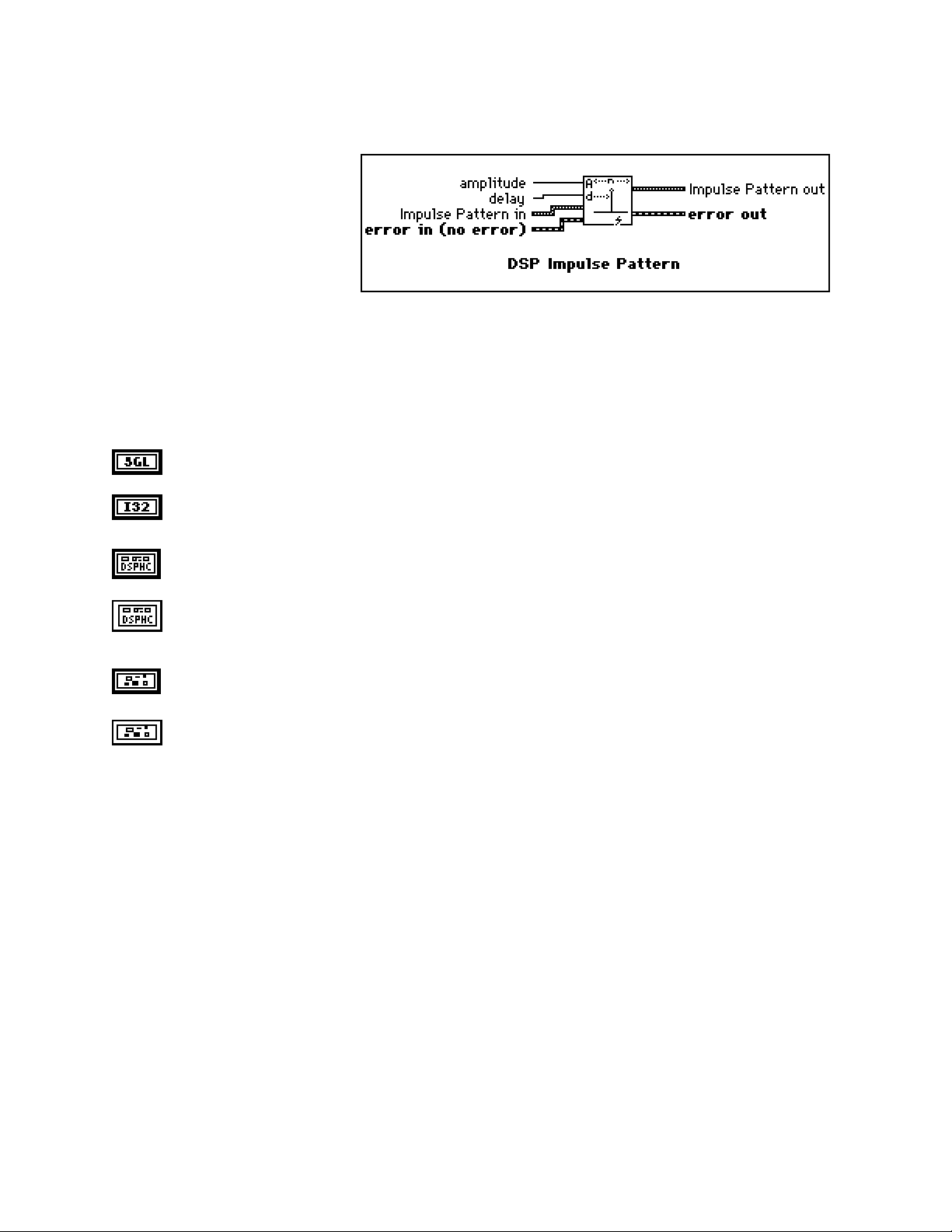
NI-DSP Analysis VI Reference Chapter 2
DSP Impulse Pattern
Generates an array containing an
impulse pattern. If the Impulse
Pattern is represented by the
sequence X, the VI generates the
pattern according to the following
formula:
a if i = d
xi =
0 elsewhere
for i = 0, 1, 2, … , n-1 ,
where a is the amplitude,
d is the delay, and
n is the number of elements in Impulse Pattern.
amplitude defaults to 1.0.
delay must be greater than or equal to 0. If delay is less than zero or greater than or equal to the size of
Impulse Pattern, the VI returns an error. delay defaults to 0.
Impulse Pattern in is a DSP Handle Cluster that indicates the memory buffer on the DSP board that
will contain the output impulse pattern.
Impulse Pattern out is a DSP Handle Cluster that is identical to Impulse Pattern in, but with the
generated pattern already stored in the memory buffer on the DSP board. The largest impulse pattern
that can be generated depends upon the amount of memory on your DSP board.
error in (no error) contains the error information from a previous VI. If an error occurs, it is passed out
error out and no other calls are made.
error out contains the error information for this call.
Part 3: NI-DSP Function Reference 2-42 NI-DSP SRM for LabVIEW for Windows
Page 78
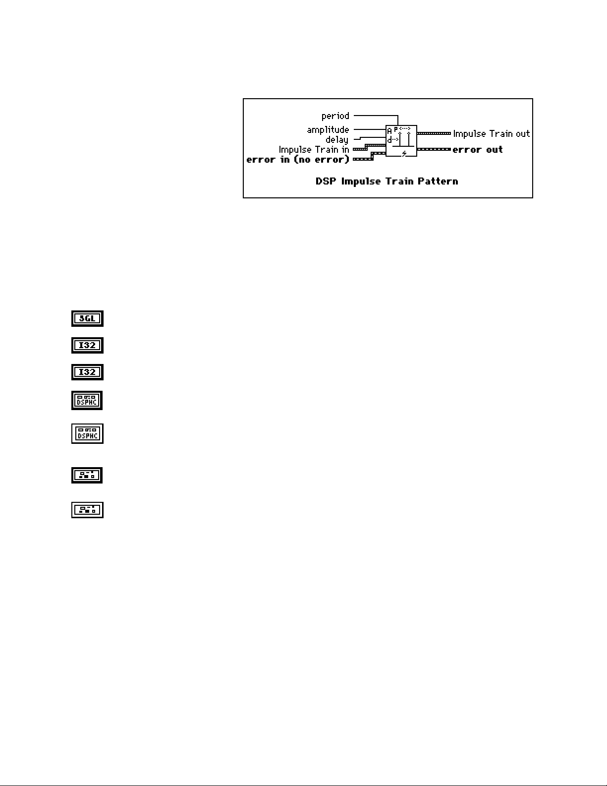
Chapter 2 NI-DSP Analysis VI Reference
DSP Impulse Train Pattern
Generates a train of impulses of value
amplitude at sample delay.
If the impulse train pattern is represented
by the sequence X, the VI generates the
pattern according to the following
formula:
amplitude if i modulo P = d
xi =
0.0 elsewhere
for i = 0, 1, 2, … , n-1 ,
where P is the period,
d is the delay, and
n is the number of elements in the impulse train.
amplitude defaults to 1.0.
delay defaults to 0.
period defaults to 1.
Impulse Train in is a DSP Handle Cluster that indicates the memory buffer on the DSP board that will
contain the output impulse train.
Impulse Train out is a DSP Handle Cluster that is identical to Impulse Train in, but with the generated
pattern already stored in the memory buffer on the DSP board. The largest impulse train that can be
generated depends upon the amount of memory on your DSP board.
error in (no error) contains the error information from a previous VI. If an error occurs, it is passed out
error out and no other calls are made.
error out contains the error information for this call.
NI-DSP SRM for LabVIEW for Windows 2-43 Part 3: NI-DSP Function Reference
Page 79
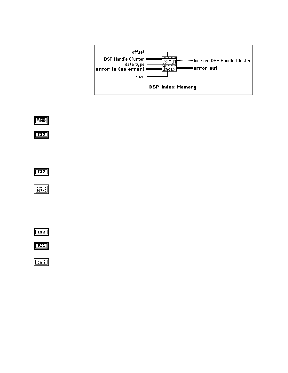
NI-DSP Analysis VI Reference Chapter 2
DSP Index Memory
Indexes into a DSP buffer
allocated in the memory
space of the specified DSP
board. The return value is
another DSP Handle Cluster.
This VI does not allocate
memory.
In order to index into a buffer
correctly, you need to indicate
what type of data is in the DSP
buffer. You must set data type to the appropriate type. data type has two options–4 bytes (for 32-bit long and
floating-point data) and 2 bytes (for 16-bit short data).
DSP Handle Cluster is a DSP Handle Cluster into which you want to index.
data type indicates the type of data in the buffer on the DSP board that is referred to by DSP Handle
Cluster. data type has two options:
0: 4 bytes (for 32-bit long and floating-point data).
1: 2 bytes (for 16-bit short data).
data type defaults to 4 bytes.
offset is the index where to start to index into the array referenced by DSP Handle Cluster. offset
defaults to 0.
Indexed DSP Handle Cluster is a DSP Handle Cluster that contains the number of size data in DSP
Handle Cluster starting from offset.
Notes: If you free a DSP Handle Cluster using the DSP Free Memory VI, then all other DSP Handle
Clusters obtained by using DSP Index Memory VI will no longer be valid.
This VI returns a new DSP Handle Cluster. If you no longer need this DSP Handle Cluster,
remember to free it.
size indicates how many elements you want to index starting from the offset. size defaults to 0.
error in (no error) contains the error information from a previous VI. If an error occurs, it is passed out
error out and no other calls are made.
error out contains the error information for this call.
Part 3: NI-DSP Function Reference 2-44 NI-DSP SRM for LabVIEW for Windows
Page 80

Chapter 2 NI-DSP Analysis VI Reference
DSP Init Memory
Initializes the memory heaps and frees all
allocations of memory on the specified DSP
board.
slot is the board ID number. slot defaults to 3.
error in (no error) contains the error information from a previous VI. If an error occurs, it is passed out
error out and no other calls are made.
error out contains the error information for this call.
NI-DSP SRM for LabVIEW for Windows 2-45 Part 3: NI-DSP Function Reference
Page 81

NI-DSP Analysis VI Reference Chapter 2
DSP Integral
Performs the discrete integration of the
sampled signal X. The integral F(t) of a
function f(t) is defined as follows:
F(t) = ∫
Let Y represent the sampled output sequence Integral X. The VI obtains the elements of Y using the following
formula:
yi =
where n is the number of elements in X,
f(t) dt .
i
1
(x
+ 4xj + x
∑
j=0
j-1
6
) dt for i = 0, 1, 2, …, n-1 ,
j+1
x-1 is specified by initial condition when i = 0, and
xn is specified by final condition when i = n-1.
The initial condition and final condition minimize the overall error by increasing the accuracy at the boundaries,
especially when the number of samples is small. Determining boundary conditions before the fact enhances
accuracy.
X is a DSP Handle Cluster that indicates the memory buffer on the DSP board that contains the input
signal array.
initial condition defaults to 0.0.
final condition defaults to 0.0.
dt is the sampling interval and must be greater than zero. If dt is less than or equal to zero, the VI
returns an error. dt defaults to 1.0.
Y in is a DSP Handle Cluster that indicates the memory buffer on the DSP board that will contain the
results of the integration of X.
Y out is a DSP Handle Cluster that is identical to Y in, but with the results of integration already stored
in the memory buffer on the DSP board.
error in (no error) contains the error information from a previous VI. If an error occurs, it is passed out
error out and no other calls are made.
error out contains the error information for this call.
The operation can be performed in place; that is, the input X and the output Y can be the same DSP Handle Cluster.
Note: You can also use the DSP Integral x(t) VI to numerically evaluate the finite integral:
b
∫
f(t) dt = F(b) - F(a) ≈ y
a
,
n-1
by extracting the last element of the output sequence Y.
Part 3: NI-DSP Function Reference 2-46 NI-DSP SRM for LabVIEW for Windows
Page 82

Chapter 2 NI-DSP Analysis VI Reference
DSP Inv Chebyshev Coeff
Generates the set of filter
coefficients to implement an
inverse IIR filter as specified
by the Chebyshev II Filter
mode. You can then pass
these coefficients to the DSP
IIR Filter VI to filter a
sequence of data.
filter type specifies the passband of the filter. filter type has four options:
0: lowpass.
1: highpass.
2: bandpass.
3: bandstop.
filter type defaults to lowpass.
sampling Freq : fs is the sampling frequency and must be greater than 0. If it is less than or equal to
zero, the VI returns an error. sampling Freq : fs defaults to 1.0.
high cutoff freq: fh is the high cutoff frequency. The VI ignores this parameter when filter type is
lowpass. high cutoff freq: fh defaults to 0.45.
low cutoff freq: fl is the low cutoff frequency. The VI ignores this parameter when filter type is
highpass. low cutoff freq: fl defaults to 0.125.
Note: fh and fl must observe the Nyquist criterion: 0 ≤ fl ≤ fh ≤ fs /2.
attenuation must be greater than 0.0. If attenuation is less than or equal to zero, the VI returns an
error. attenuation defaults to 60.0.
order must be greater than zero. If the filter order is less than or equal to zero, the VI returns an error.
order defaults to 2.
Forward Coefficients in is a DSP Handle Cluster that indicates the memory buffer on the DSP board
that will contain the forward coefficients.
Feedback Coefficients in is a DSP Handle Cluster that indicates the memory buffer on the DSP board
that will contain the feedback coefficients.
Forward Coefficients out is a DSP Handle Cluster that is identical to Forward Coefficients in, but
with the forward coefficients already stored in the memory buffer on the DSP board.
Feedback Coefficients out is a DSP Handle Cluster that is identical to Feedback Coefficients in, but
with the feedback coefficients already stored in the memory buffer on the DSP board.
NI-DSP SRM for LabVIEW for Windows 2-47 Part 3: NI-DSP Function Reference
Page 83

NI-DSP Analysis VI Reference Chapter 2
error in (no error) contains the error information from a previous VI. If an error occurs, it is passed out
error out and no other calls are made.
error out contains the error information for this call.
Parameter Discussion
The arrays Forward Coefficients in/out and Feedback Coefficients in/out must have a size of at least (order + 1)
for lowpass and highpass filters. The arrays Forward Coefficients in/out and Feedback Coefficients in/out must
have a size of at least (2*order + 1) for bandpass and bandstop filters.
DSP Inverse FFT
Computes the inverse Fourier transform of the
complex input sequence FFT {X}. If Y
represents the output sequence, then:
Y = F-1{X}.
Re FFT{X} is a DSP Handle Cluster that indicates the memory buffer on the DSP board that contains
the real part of input signal array FFT {X}.
Im FFT{X} is a DSP Handle Cluster that indicates the memory buffer on the DSP board that contains
the imaginary part of input signal array FFT {X}.
Notes: The number of elements for the input array must be the power of two. If the size of Re
FFT{X} is different from the size of Im FFT{X}, the VI uses the smaller number as the size of
the inverse FFT.
The operation is performed in place and the input array Re FFT{X } and Im FFT{X} is
overwritten by Re {X} and Im {X}.
The largest inverse FFT that can be computed depends upon the amount of memory on your
DSP board.
Re {X} is a DSP Handle Cluster that is identical to Re FFT{X }, but with the real part of X already
stored in the memory buffer on the DSP board.
Im {X} is a DSP Handle Cluster that is identical to the Im FFT{X} but with the imaginary part of X
already stored in the memory buffer on the DSP board.
error in (no error) contains the error information from a previous VI. If an error occurs, it is passed out
error out and no other calls are made.
error out contains the error information for this call.
Part 3: NI-DSP Function Reference 2-48 NI-DSP SRM for LabVIEW for Windows
Page 84

Chapter 2 NI-DSP Analysis VI Reference
DSP Inverse FHT
Computes the inverse fast Hartley transform of
the input sequence FHT {X}. The inverse
Hartley transform of a function X(f) is defined
as
∞
x(t) = ∫
where cas(x) = cos(x) + sin(x).
If Y represents the output sequence X, the VI calculates Y through the discrete implementation of the inverse
Hartley integral:
Yk =
where n is the number of elements in X.
The inverse Hartley transform maps real-valued frequency sequences into real-valued sequences. You can use it
instead of the inverse Fourier transform to convolve, deconvolve, and correlate signals. Furthermore, you can derive
the Fourier transform from the Hartley transform.
X(f) cas(2πft) df
-∞
n-1
1
Xi cas
∑
n
i=0
2π ik
for k = 0, 1, 2, … , n-1
()
n
See the description of the DSP FHT VI for a comparison of the Fourier and Hartley transforms.
FHT {X} is a DSP Handle Cluster that indicates the memory buffer on the DSP board that contains the
input signal array.
Notes: The number of elements for the input array must be a power of 2.
The operation is performed in place and the input array FHT {X} is overwritten by
the output array X.
The largest inverse FHT that can be computed depends upon the amount of memory in your
DSP board.
X is a DSP Handle Cluster that is identical to FHT {X}, but with the results of inverse FHT {X } already
stored in the memory buffer on the DSP board.
error in (no error) contains the error information from a previous VI. If an error occurs, it is passed out
error out and no other calls are made.
error out contains the error information for this call.
NI-DSP SRM for LabVIEW for Windows 2-49 Part 3: NI-DSP Function Reference
Page 85

NI-DSP Analysis VI Reference Chapter 2
DSP Kaiser-Bessel Window
Applies a Kaiser-Bessel window to the
input sequence X. If Y represents the
output sequence Kaiser-Bessel{X}, the
elements of Y are obtained using the
formula:
1.0 - a
β
()
o
2
yi = xi
β
I
o
I
for i = 0, 1, 2, … n - 1
i - k
a =
k
n-1
k =
,
2
where n is the number of elements in X, and
Io(•) is the zeroth-order modified Bessel function.
X is a DSP Handle Cluster that indicates the memory buffer on the DSP board that contains the input
signal array.
Note: The operation is performed in place and the input array X is overwritten by the output
Kaiser-Bessel {X}.
beta is proportional to the sidelobe attenuation–that is, the larger beta is, the greater the sidelobe
attenuation is. beta defaults to 0.0.
Kaiser-Bessel {X} is a DSP Handle Cluster that is identical to X, but with the results of
Kaiser-Bessel {X} already stored in the memory buffer on the DSP board.
error in (no error) contains the error information from a previous VI. If an error occurs, it is passed out
error out and no other calls are made.
error out contains the error information for this call.
Part 3: NI-DSP Function Reference 2-50 NI-DSP SRM for LabVIEW for Windows
Page 86

Chapter 2 NI-DSP Analysis VI Reference
DSP Linear Evaluation
Performs a linear evaluation of the input array
X. The i
obtained using the following formula:
where n is the number of elements in X.
th
element of the output array Y is
Y(i) = a* X(i) + b for i = 0, 1, 2, …, n-1,
X is a DSP Handle Cluster that indicates the memory buffer on the DSP board that contains the input
signal array X.
a is the multiplicative constant. a defaults to 1.0.
b is the additive constant. b defaults to 0.0.
Y in is a DSP Handle Cluster that indicates the memory buffer on the DSP board that will contain the
results of output array.
Y out is a DSP Handle Cluster that is identical to Y in, but with the results already stored in the memory
buffer on the DSP board.
error in (no error) contains the error information from a previous VI. If an error occurs, it is passed out
error out and no other calls are made.
error out contains the error information for this call.
The operation can be performed in place; that is, the input and output arrays can be the same DSP Handle Cluster.
DSP Load
Downloads a library specified by path name to
the DSP board in slot. path name must contain
the full path name of a valid COFF file (.out
file).
slot is the board ID number. slot defaults to 3.
path name is the path name of the .out file.
error in (no error) contains the error information from a previous VI. If an error occurs, it is passed out
error out and no other calls are made.
error out contains the error information for this call.
NI-DSP SRM for LabVIEW for Windows 2-51 Part 3: NI-DSP Function Reference
Page 87

NI-DSP Analysis VI Reference Chapter 2
DSP Log
Computes the logarithm base 10 of the X input
array. The ith element of resulting array is
obtained by using the following formula:
y(i) = log10 (X(i)) * mult
for i = 0, 1, 2, …, n-1,
where n is the number of elements in X.
This VI is useful for converting values that represent power to decibels. This VI returns the most negative number
for any input less than or equal to zero.
X is a DSP Handle Cluster that indicates the memory buffer on the DSP board that contains the input
signal array.
mult defaults to 1.0.
Y in is a DSP Handle Cluster that indicates the memory buffer on the DSP board that will contain the
results of logarithm X.
Y out is a DSP Handle Cluster that is identical to Y in, but with the results of logarithm X already stored
in the memory buffer on the DSP board.
error in (no error) contains the error information from a previous VI. If an error occurs, it is passed out
error out and no other calls are made.
error out contains the error information for this call.
Part 3: NI-DSP Function Reference 2-52 NI-DSP SRM for LabVIEW for Windows
Page 88

Chapter 2 NI-DSP Analysis VI Reference
DSP Max & Min
Finds the maximum and minimum values in the
input array, as well as the respective indices of
the occurrence of the maximum and minimum
values.
X is a DSP Handle Cluster that indicates the memory buffer on the DSP board that contains the input
signal array X.
max value is the maximum value of the input array.
max index is the index into the input array where maximum occurred.
min value is the minimum value of the input array.
min index is the index into the input array where minimum occurred.
error in (no error) contains the error information from a previous VI. If an error occurs, it is passed out
error out and no other calls are made.
error out contains the error information for this call.
NI-DSP SRM for LabVIEW for Windows 2-53 Part 3: NI-DSP Function Reference
Page 89

NI-DSP Analysis VI Reference Chapter 2
DSP Median Filter
Applies a median filter of rank to the
input sequence X. The median filter is a
nonlinear filter that combines lowpass
filters characteristics (to remove highfrequency noise) and high-frequency
characteristics (to detect edges).
If Y represents the output sequence
Filtered Data, if Ji represents a subset
of the input sequence X centered about the i
th
element of x:
Ji = {x
, x
, …, x
i-r
i-r+1
, xi, x
i-1
, …, x
i+1
i+r-1
, x
},
i+r
and if the indexed elements outside the range of X equal zero, the VI obtains the elements of Y using:
yi = Median(Ji) for i = 0, 1, 2, …, n-1,
where n is the number of elements in the input sequence X, and
r is the filter rank.
X is a DSP Handle Cluster that indicates the memory buffer on the DSP board that contains the input
data array. The number of elements in X must be greater than the rank:
n>r≥0.
If the number of elements in X is less than or equal to rank, the VI returns an error.
rank must be greater than or equal to zero. If rank is less than zero, the VI returns an error. rank
defaults to 2.
Filtered Data in is a DSP Handle Cluster that indicates the memory buffer on the DSP board that will
contain the filtered data output.
Filtered Data out is a DSP Handle Cluster that is identical to Filtered Data in, but with the filtered data
already stored in the memory buffer on the DSP board.
error in (no error) contains the error information from a previous VI. If an error occurs, it is passed out
error out and no other calls are made.
error out contains the error information for this call.
The operation cannot be performed in place; that is, the input X and the output Filtered Data cannot be the same
DSP Handle Cluster.
Part 3: NI-DSP Function Reference 2-54 NI-DSP SRM for LabVIEW for Windows
Page 90
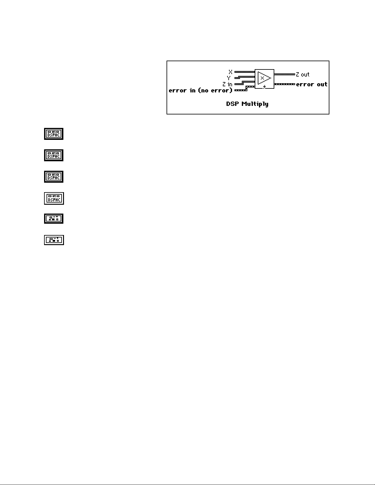
Chapter 2 NI-DSP Analysis VI Reference
DSP Multiply
Multiply array X by array Y. The ith element
of the output array Z is obtained using the
following formula:
Z(i) = X(i) * Y(i) for i = 0, 1, 2, …, n-1,
where n is the smaller number of elements in X
and Y.
X is a DSP Handle Cluster that indicates the memory buffer on the DSP board that contains the input
signal array X.
Y is a DSP Handle Cluster that indicates the memory buffer on the DSP board that contains the input
signal array Y.
Z in is a DSP Handle Cluster that indicates the memory buffer on the DSP board that will contain the
results of X(i) * Y(i).
Z out is a DSP Handle Cluster that is identical to Z in, but with the multiplied results already stored in
the memory buffer on the DSP board.
error in (no error) contains the error information from a previous VI. If an error occurs, it is passed out
error out and no other calls are made.
error out contains the error information for this call.
The operation can be performed in place; that is, the input and output arrays can be the same DSP Handle Cluster.
NI-DSP SRM for LabVIEW for Windows 2-55 Part 3: NI-DSP Function Reference
Page 91

NI-DSP Analysis VI Reference Chapter 2
DSP Parks-McClellan
Generates a set of linear-phase finite impulse
response multiband digital filter coefficients
using the number of taps, sampling
frequency, filter type, and Band Parameters.
# of taps is the total number of coefficients in H. A tap corresponds to a multiplication and an addition.
If there are n taps, every filtered sample requires n multiplications and n additions. # of taps must be
greater than 0. If # of taps is less than or equal to zero, the VI returns an error. # of taps defaults to 32.
sampling freq : fs defaults to 1.0.
Band Parameters is a cluster. Each cluster element contains the necessary information associated with
each band for the FIR design. Each cluster contains four elements, as shown in the following figure:
The Band Parameters cluster must contain at least one element, that is, one band.
amplitude is a DSP Handle Cluster that indicates the memory buffer on the DSP board that
contains the desired amplitude for each band.
lower freq is a DSP Handle Cluster that indicates the memory buffer on the DSP board that
contains the lower frequency bands.
higher freq is a DSP Handle Cluster that indicates the memory buffer on the DSP board
that contains the upper frequency bands.
Part 3: NI-DSP Function Reference 2-56 NI-DSP SRM for LabVIEW for Windows
Page 92

Chapter 2 NI-DSP Analysis VI Reference
weighted ripple is a DSP Handle Cluster that indicates the memory buffer on the DSP
board that contains the weighting factor for each band.
For each band, higher freq must be greater than lower freq, and for adjacent bands, lower
freq in the higher band must be greater than higher freq in the lower band,
f
> f
, for i = 0, 1, 2, …, m-1,
h
l
i
i
f
> f
l
where f
i+1
, for i = 0, 1, 2, …, m-2,
h
i
represents the lower freq in the i
l
i
th
band, and f
represents the higher freq in the i
h
i
th
band.
The higher freq in the last band must observe the Nyquist criterion:
f
≤ 0.5fs ,
h
m-1
where fs is the sampling frequency.
If Band Parameters does not contain any elements, or if any of the preceding frequency
conditions is violated, the VI returns an error.
filter type has three options:
0: multiband.
1: differentiator.
2: Hilbert.
filter type defaults to multiband.
ripple is the optimal ripple the VI computes and is a measure of deviation from the ideal filter
specifications.
H in is a DSP Handle Cluster that indicates the memory buffer on the DSP board that will contain the
FIR coefficients.
H out is a DSP Handle Cluster that is identical to H in, but with the coefficients already stored in the
memory buffer on the DSP board.
error in (no error) contains the error information from a previous VI. If an error occurs, it is passed out
error out and no other calls are made.
error out contains the error information for this call.
Note: The DSP Parks-McClellan VI finds the coefficients using iterative techniques based upon an error criterion.
Although you specify valid filter parameters, the algorithm may fail to converge.
The DSP Parks-McClellan VI generates only the filter coefficients. It does not perform the filtering
function. To filter a sequence X using the set of FIR filter coefficients H, use the DSP Convolution VI with
X and H as the input sequences.
NI-DSP SRM for LabVIEW for Windows 2-57 Part 3: NI-DSP Function Reference
Page 93

NI-DSP Analysis VI Reference Chapter 2
The equi-ripple filters use a similar technique to filter the data.
Part 3: NI-DSP Function Reference 2-58 NI-DSP SRM for LabVIEW for Windows
Page 94
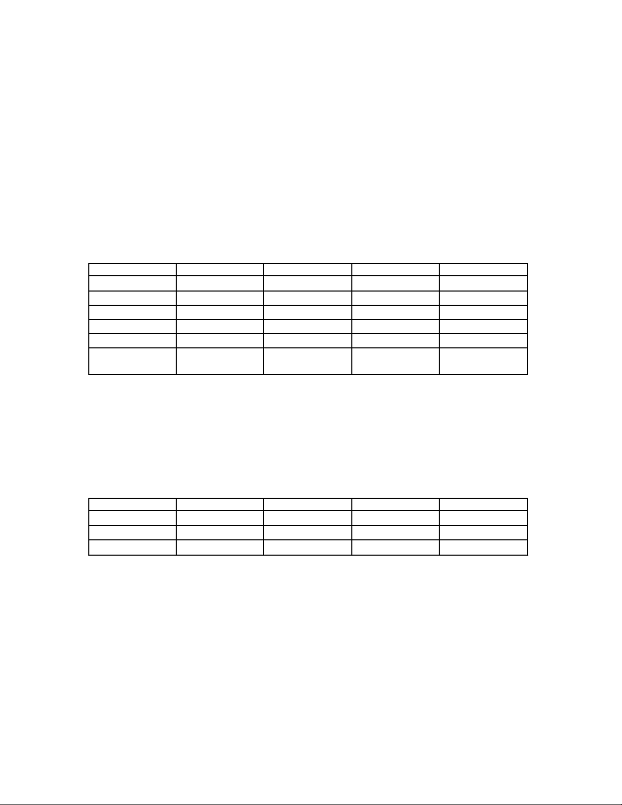
Chapter 2 NI-DSP Analysis VI Reference
Parameter Discussion
The weights are usually the same for every band and inversely proportional to frequency f for a differentiate. The
amplitudes of the bands are usually the same for every band and form a slope for a differentiation. The designed
filter is unconstrained, that is the frequency response in transitional period specifications is not guaranteed. Adjust
the parameters if there are discrepancies between specifications and results.
Generally, when type = multiband and bands ≥ 2, the DSP Parks-McClellan VI designs a multiband filter. When
filter type = differentiator and bands = 1, the DSP Parks-McClellan VI designs a differentiation. When
filter type = Hilbert and bands = 1, the DSP Parks-McClellan VI designs a Hilbert transform. The following tables
contain the brief requirements you must meet when you design different types of filters. For more information,
please refer to Digital Filter Design by Parks and Burrus, or "A Computer Program for Designing Optimum FIR
Linear Phase Digital Filters," by McClellan, Parks, and Rabiner.
When filter type = Multiband:
Filter Band Type LowPass HighPass BandPass BandStop
# of Bands (n) 2 2 ≥3 ≥3
# of taps odd/even odd odd/even odd
fl[0] 0.0 0.0 0.0 0.0
fh[n-1] 0.5fs 0.5fs 0.5fs 0.5fs
amp[0] >0.0 ≥0.0 ≥0.0 >0.0
amp[n-1] 0.0(for even taps)
≥0.0(for odd taps)
>0.0 0.0(for even taps)
≥0.0(for odd taps)
>0.0
fl[0] represents the first value in the array of Lower Freq.
fh[n-1] represents the last value in the array of Higher Freq.
amp[0] represents the first value in the array of Amplitude.
amp[n-1] represents the last value in the array of Amplitude.
fs is the sample frequency.
When filter type = Differentiator or Hilbert:
Filter Type Diff(odd) Diff(even) Hilbert(odd) Hilbert(even)
bands(n) ≥1 ≥1 ≥1 ≥1
fl[0] 0.0 0.0 0.0+∆ 0.0+∆
fh[n-1] 0.5fs-∆ 0.5fs 0.5fs-∆ 0.5fs
odd or even in the table refers to the value of the # of taps.
fl[0] represents the first value in the array of Lower Freq.
fh[n-1] represents the last value in the array of Higher Freq.
fs is the sample frequency.
∆ is a small number that specifies the transitional band.
Although the DSP Parks-McClellan VI is the most flexible way to design a FIR linear phase filter, it has more
complex parameters and requires some DSP knowledge. You may find it more convenient to use DSP Equi-Ripple
LowPass, DSP Equi-Ripple HighPass, DSP Equi-Ripple BandPass, and DSP Equi-Ripple BandStop. These
functions, which provide lowpass, highpass, bandpass and bandstop FIR filters with equal weighting factors in all
bands, are special cases of the DSP Parks-McClellan VI with simplified parameters.
NI-DSP SRM for LabVIEW for Windows 2-59 Part 3: NI-DSP Function Reference
Page 95
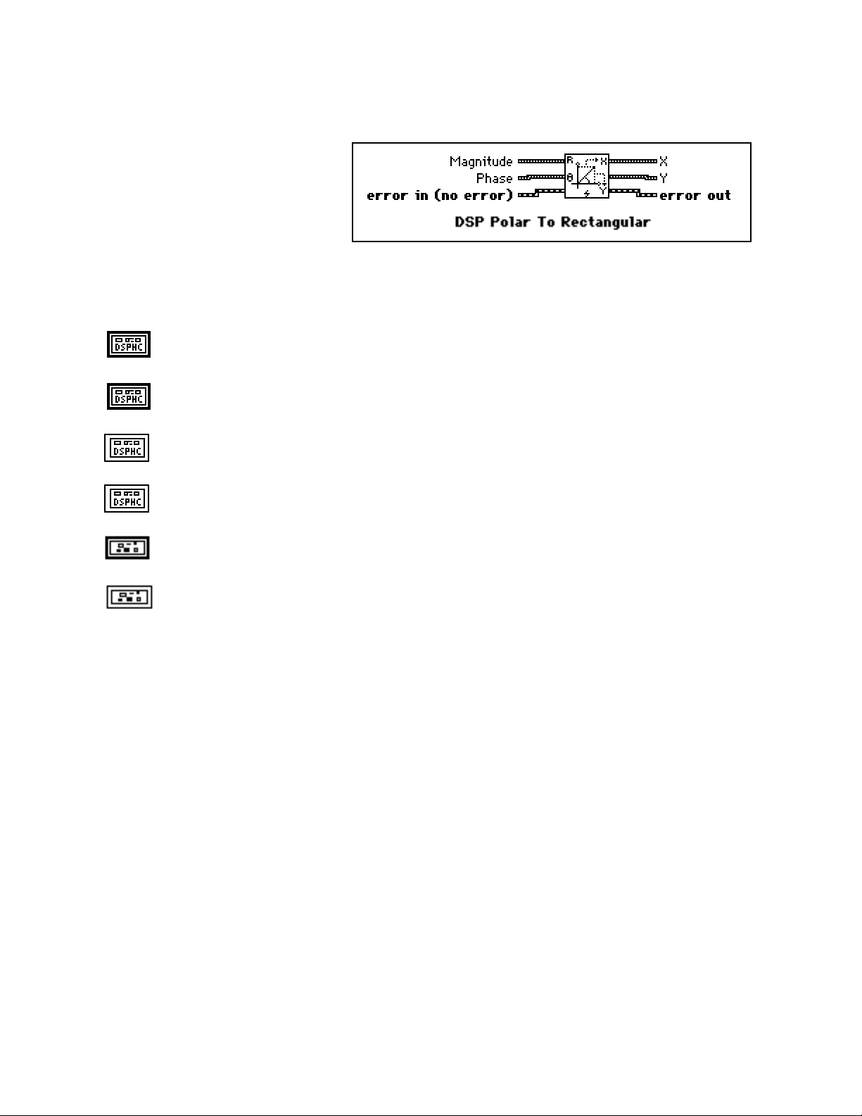
NI-DSP Analysis VI Reference Chapter 2
DSP Polar to Rectangular
Converts a set of polar coordinate points
(Magnitude, Phase) to a set of rectangular
coordinate points (X, Y). The ith elements
of the rectangular set is obtained using the
following formulas:
X(i) = Magnitude(i) * cos(Phase(i))
Y(i) = Magnitude(i) * sin(Phase(i))
Note: The operation is performed in place and the input arrays Magnitude and Phase are overwritten by X and
Y.
Magnitude is the DSP Handle Cluster that indicates the memory buffer on the DSP board that
contains the input signal array Magnitude.
Phase is the DSP Handle Cluster that indicates the memory buffer on the DSP board that contains
the input signal array Phase.
X is the DSP Handle Cluster that is identical to Magnitude but with the caculated rectangular
coordinate values already stored in the memory buffer on the DSP board.
Y is the DSP Handle Cluster that is identical to Phase but with the caculated rectangular coordinate
values already stored in the memory buffer on the DSP board.
error in(no error) contains the error information from a previous VI. If an error occurs, it is passed
out error out and no other calls are made.
error out contains the error information for this call.
Part 3: NI-DSP Function Reference 2-60 NI-DSP SRM for LabVIEW for Windows
Page 96

Chapter 2 NI-DSP Analysis VI Reference
DSP Polynomial Evaluation
Performs a polynomial evaluation on the input
array X. The i
is obtained using the following formula:
Y(i) = ∑ (Coefficients(j) * X(i)j)
for i = 0, 1, 2, …, n-1,
where n is the number of elements in X and k is the number of elements in Coefficients.
th
element of the output array Y
k-1
j=0
X is a DSP Handle Cluster that indicates the memory buffer on the DSP board that contains the input
signal array X.
Coefficients is a DSP Handle Cluster that indicates the memory buffer on the DSP board that contains
the coefficients array.
Y in is a DSP Handle Cluster that indicates the memory buffer on the DSP board that will contain the
results of output array.
Y out is a DSP Handle Cluster that is identical to Y in, but with the results already stored in the memory
buffer on the DSP board.
error in (no error) contains the error information from a previous VI. If an error occurs, it is passed out
error out and no other calls are made.
error out contains the error information for this call.
The operation can be performed in place; that is, the input X and the output Y can be the same DSP Handle Cluster.
NI-DSP SRM for LabVIEW for Windows 2-61 Part 3: NI-DSP Function Reference
Page 97

Chapter 2 NI-DSP Analysis VI Reference
DSP Power Spectrum
Computes the Power Spectrum of the
input sequence X. The Power Spectrum
Sxx(f) of a function x(t) is defined as
Sxx(f) = X*(f)X(f) = | X(f) | 2 ,
whereX(f) = F{x(t)}, and X*(f) is the
complex conjugate of X(f).
X is a DSP Handle Cluster that indicates the memory buffer on the DSP board that contains the input
signal array.
Notes:The number of elements for the input array must be a power of two.
The operation is performed in place and the input array X is overwritten by the output Power
Spectrum.
The largest power spectrum that can be computed depends upon the amount of memory on your
DSP board.
This VI allocates a temporary workspace on the DSP board equal to the size of the input signal
array.
Power Spectrum is a DSP Handle Cluster that is identical to X, but with the results of Power
Spectrum already stored in the memory buffer on the DSP board.
error in (no error) contains the error information from a previous VI. If an error occurs, it is passed out
error out and no other calls are made.
error out contains the error information for this call.
DSP Product
Finds the product of the elements of the input
array X. The product of the elements is
obtained using the following formula:
product = X(i)
where n is the smaller number of elements in X.
n−1
∏
i=0
X is a DSP Handle Cluster that indicates the memory buffer on the DSP board that contains the input
signal array X.
product is the product of the elements in X.
error in (no error) contains the error information from a previous VI. If an error occurs, it is passed out
error out and no other calls are made.
error out contains the error information for this call.
NI-DSP SRM for LabVIEW for Windows 2-62 Part 3: NI-DSP Function Reference
Page 98

NI-DSP Analysis VI Reference Chapter 2
DSP Pulse Pattern
Generates an array containing a pulse
pattern. If Pulse Pattern is represented
by the sequence X, then the pattern is
generated according to the following
formula:
a if d ≤ i < last
xi =
0 elsewhere
for i = 0, 1, 2, … , n-1 ,
last = d + w ,
wherea is the amplitude,
d is the delay,
w is the width, and
n is the number of elements in Pulse Pattern.
amplitude defaults to 1.0.
delay must be greater than or equal to 0. delay defaults to 0.
width must be greater than or equal to 0. width defaults to 1.
Pulse Pattern in is a DSP Handle Cluster that indicates the memory buffer on the DSP board that will
contain the output pulse pattern.
Pulse Pattern out is a DSP Handle Cluster that is identical to Pulse Pattern in, but with the generated
pattern already stored in the memory buffer on the DSP board. The largest pulse pattern that can be
generated depends upon the amount of memory on your DSP board.
error in (no error) contains the error information from a previous VI. If an error occurs, it is passed out
error out and no other calls are made.
error out contains the error information for this call.
Part 3: NI-DSP Function Reference 2-63 NI-DSP SRM for LabVIEW for Windows
Page 99

Chapter 2 NI-DSP Analysis VI Reference
DSP Ramp Pattern
Generates an array containing a ramp
pattern. If the Ramp Pattern is
represented by the sequence X, then the
pattern is generated according to the
formula:
xi = x0 + i ∆x
for i = 0, 1, 2, … , n-1 ,
x
- x
n-1
where∆x =
x
is the final,
n-1
x0 is the init, and
n is the number of elements in Ramp Pattern.
The Ramp Pattern VI does not impose conditions on the relationship between init and final. The VI can therefore
generate ramp-up and ramp-down patterns.
final defaults to 0.0.
n - 1
0
,
init defaults to 1.0.
Ramp Pattern in is a DSP Handle Cluster that indicates the memory buffer on the DSP board that will
contain the output ramp pattern.
Ramp Pattern out is a DSP Handle Cluster that is identical to Ramp Pattern in, but with the generated
pattern already stored in the memory buffer on the DSP board. The largest ramp pattern that can be
generated depends upon the amount of memory on your DSP board.
error in (no error) contains the error information from a previous VI. If an error occurs, it is passed out
error out and no other calls are made.
error out contains the error information for this call.
NI-DSP SRM for LabVIEW for Windows 2-64 Part 3: NI-DSP Function Reference
Page 100

NI-DSP Analysis VI Reference Chapter 2
DSP Random Pattern
Generates a uniformly distributed
pseudorandom pattern whose values
are in the range [0:1]. The sequence is
generated using the Very-Long-Cycle
random number generator algorithm.
seed < 65536.0. If seed > 0.0, the generated noise will be the same in repeated invocations if the seed
value does not change. If seed ≤ 0.0, the VI generates a random value to use as the seed, and the noise
differs in repeated invocations although the value in seed does not change. seed defaults to 0.0.
Random Pattern in is a DSP Handle Cluster that indicates the memory buffer on the DSP board that
will contain the output random pattern.
Random Pattern out is a DSP Handle Cluster that is identical to Random Pattern in, but with the
generated pattern already stored in the memory buffer on the DSP board. The largest random pattern
that can be generated depends upon the amount of memory on your DSP board.
error in (no error) contains the error information from a previous VI. If an error occurs, it is passed out
error out and no other calls are made.
error out contains the error information for this call.
Part 3: NI-DSP Function Reference 2-65 NI-DSP SRM for LabVIEW for Windows
 Loading...