

National Geographic NG90EQ User Manual

NG90EQ
Maksutov-Cassegrain
Telescope
Instructions
and
Owner’s Manual
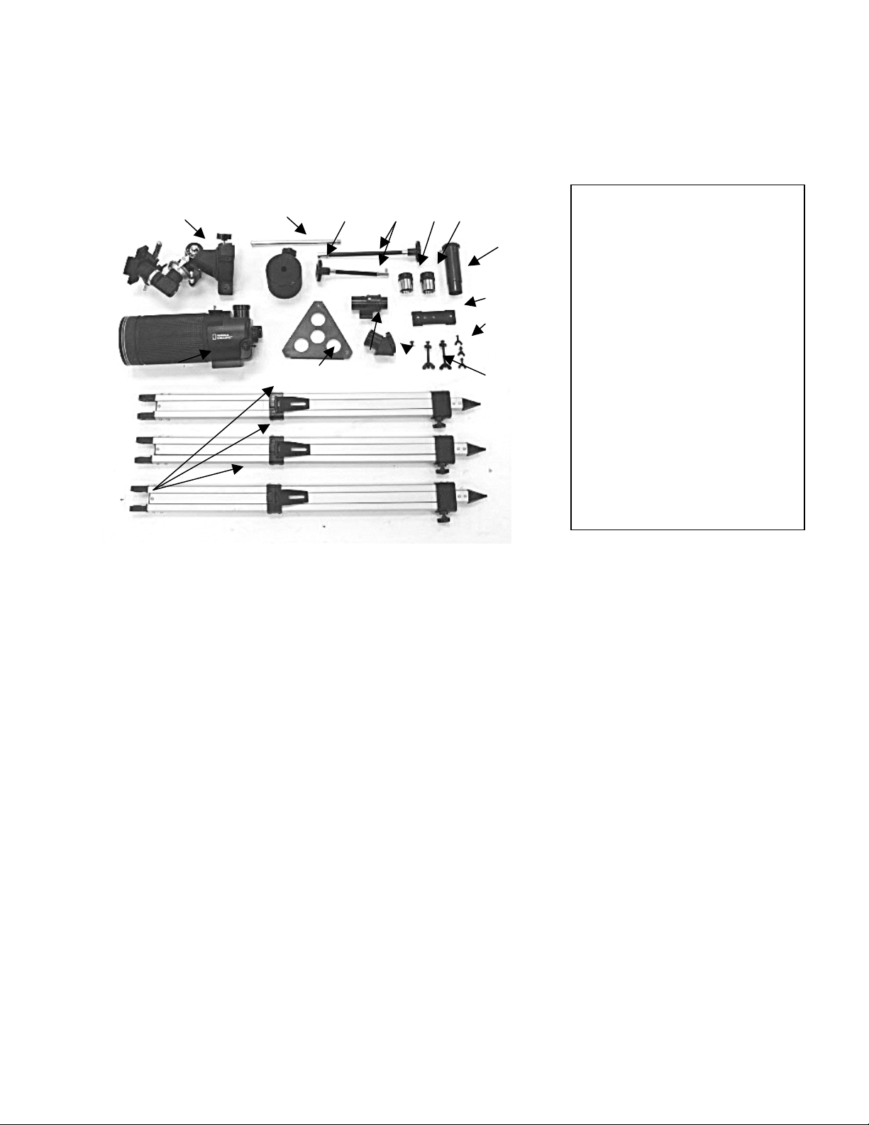
Parts of your NG90EQ Telescope:
A. Equatorial mount
B. Counterweight shaft
C. Counterweight
D. Slow-motion control knobs (2)
E. 9-mm eyepiece
F. 25-mm eyepiece
G. 3X Barlow lens
H. Main optical unit
I. Accessory tray
J. Finder scope
K. 45º prism
L. Mounting plate
M. Accessory tray screws (3)
N. Tripod bolts (3)
O. Tripod legs (3)
O
H
A
B
C
D E F
G
L
M
I
J K
N
A. Equatorial mount G. 3X Barlow lens M. Accessory tray
screws
a. Counterweight H. Main optical unit N. Tripod leg
bolts
B. Counterweight shaft I. Accessory tray O. Tripod Legs
C. Slow-motion control knobs J. Finder scope
D. 9mm eyepiece K. 45º Diagonal prism
E. 25mm eyepiece L. Mounting plate
WARNING!
NEVER aim your telescope at the sun or even close to the sun!
Instant and irreversible damage can occur,
including blindness!
Do not let children use any telescope without adult supervision.
2
Introduction
Congratulations on your purchase of a precision-crafted NATIONAL GEOGRAPHIC™
telescope. With proper care and handling of your telescope, you will enjoy the pleasure
of looking at nature’s wondrous sights through the eye of this instrument for many
years.
The NG90EQ has been designed to provide views of the moon’s craters, Jupiter’s major
moons, and Saturn’s rings, in addition to dozens of galaxies, star clusters, and nebulae.
As a terrestrial (land) telescope, the NG90EQ delivers great views of mountains,
valleys, and many other features of the world around us. You can also use the NG90EQ
to study animals and landscapes at a distance. To obtain the best performance from
your telescope, please read this manual carefully and completely.
CHOKING HAZARD
Small parts. Not
children under 3 years.
!
WARNING!
suitable for
3
ASSEMBLY
1) Carefully remove all parts from the cardboard cartons and lay them on a table or
on the floor in order to take an inventory of all the pieces. Keep your box for storage
or in case you ever need to ship your telescope.
2) Each aluminum tripod leg can extend to almost double its closed length. This
enables the height of the telescope to be adjusted to comfortably suit most users.
Each leg is equipped with a locking knob that can be loosened to perform this
adjustment and then retightened. These locking knobs may already be attached to
the tripod legs, or they may be packaged in a small plastic bag. If they are already
attached you can extend the tripod legs to the desired height and then tighten these
knobs. If they are separately packaged you will have to first insert them into the
threaded holes located on the side of the black collar near the bottom of each closed
tripod leg.
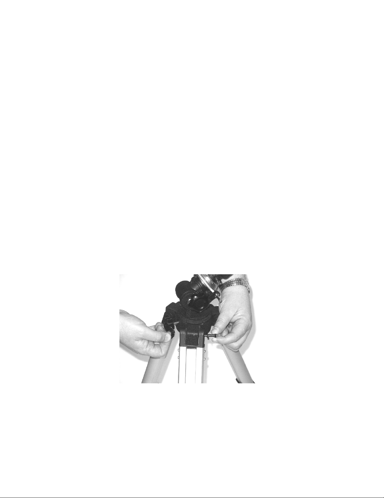
3) The tripod legs now need to be attached to the equatorial mount. The top of each
leg is attached with a tripod bolt passed through the holes at the top of each leg.
Position one of the three arms of the equatorial mount so that it fits between the leg
sections. Insert a bolt through the first tripod section, then through the equatorial
mount arm, and finally through the second leg section (See Fig. 1). You will note that
one of the leg sections has a hexagonal (8-sided) hole. This is the side from which
you insert the bolt. When the bolt comes out the other side, place a round washer
and a then a wing nut over the bolt. Tighten the wing nut firmly. NOTE: Each tripod
leg has a black metal flap about halfway down its length. This is a bracket to
hold the accessory tray and must it be located on the inward-facing side of the
tripod leg.
(Fig. 1)
4) Attach the accessory tray to the tripod by inserting an accessory tray screw
downward through each of the three small holes located near the edge of the
accessory tray. Lift up the black metal accessory tray bracket on one tripod leg so
that it is at a right angle to the leg. Push the accessory tray screw through the
accessory tray and then through the slot in the accessory tray bracket. Place a
washer then a wing nut over the screw and tighten the wing nut finger tight (See Fig.
2). Repeat this procedure for the other two accessory tray brackets (See Fig. 3).
4
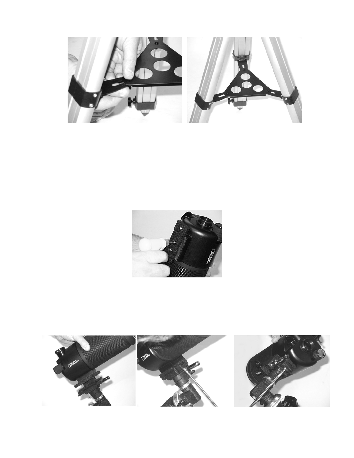
(Fig. 2) (Fig. 3)
5) The main optical unit is attached to the equatorial mount with a black cast metal
mounting plate. This mounting plate has four chromed screws mounted in it. Remove
all four screws. The mounting plate has one smooth face and one face with small
ridges. Place the smooth face against the underside of the main optical unit. Then
insert the two slotted chromed screws through the inner holes so that they engage
with the two threaded holes on the underside of the main optical unit. Tighten these
with a screwdriver (See Fig. 4).
(Fig. 4)
6) Position the main optical unit, with the mounting plate attached, over the equatorial
mount as shown in Fig. 5. Insert the two chromed screws with the Phillips (+) heads into
the two holes in the equatorial mount so that they engage the two holes at the ends of
the mounting plate. Tighten with a screwdriver (See Fig. 6 and Fig. 7).
(Fig. 5) (Fig. 6) (Fig. 7)
5
 Loading...